EP2928048A1 - Moteur électrique - Google Patents
Moteur électrique Download PDFInfo
- Publication number
- EP2928048A1 EP2928048A1 EP13857849.7A EP13857849A EP2928048A1 EP 2928048 A1 EP2928048 A1 EP 2928048A1 EP 13857849 A EP13857849 A EP 13857849A EP 2928048 A1 EP2928048 A1 EP 2928048A1
- Authority
- EP
- European Patent Office
- Prior art keywords
- small
- stator
- phase
- coil
- terminals
- Prior art date
- Legal status (The legal status is an assumption and is not a legal conclusion. Google has not performed a legal analysis and makes no representation as to the accuracy of the status listed.)
- Withdrawn
Links
- 238000004804 winding Methods 0.000 claims abstract description 25
- 238000010586 diagram Methods 0.000 description 6
- 239000012212 insulator Substances 0.000 description 6
- 230000000694 effects Effects 0.000 description 4
- 239000011347 resin Substances 0.000 description 4
- 229920005989 resin Polymers 0.000 description 4
- 238000010030 laminating Methods 0.000 description 2
- 229910052779 Neodymium Inorganic materials 0.000 description 1
- 229910000831 Steel Inorganic materials 0.000 description 1
- 238000005452 bending Methods 0.000 description 1
- 230000004907 flux Effects 0.000 description 1
- 239000011810 insulating material Substances 0.000 description 1
- 239000012774 insulation material Substances 0.000 description 1
- 239000000696 magnetic material Substances 0.000 description 1
- 229910052751 metal Inorganic materials 0.000 description 1
- 239000002184 metal Substances 0.000 description 1
- QEFYFXOXNSNQGX-UHFFFAOYSA-N neodymium atom Chemical compound [Nd] QEFYFXOXNSNQGX-UHFFFAOYSA-N 0.000 description 1
- 230000007935 neutral effect Effects 0.000 description 1
- 238000007789 sealing Methods 0.000 description 1
- 239000010959 steel Substances 0.000 description 1
Images



Classifications
-
- H—ELECTRICITY
- H02—GENERATION; CONVERSION OR DISTRIBUTION OF ELECTRIC POWER
- H02K—DYNAMO-ELECTRIC MACHINES
- H02K3/00—Details of windings
- H02K3/04—Windings characterised by the conductor shape, form or construction, e.g. with bar conductors
- H02K3/28—Layout of windings or of connections between windings
-
- H—ELECTRICITY
- H02—GENERATION; CONVERSION OR DISTRIBUTION OF ELECTRIC POWER
- H02K—DYNAMO-ELECTRIC MACHINES
- H02K3/00—Details of windings
- H02K3/46—Fastening of windings on the stator or rotor structure
- H02K3/52—Fastening salient pole windings or connections thereto
- H02K3/521—Fastening salient pole windings or connections thereto applicable to stators only
- H02K3/522—Fastening salient pole windings or connections thereto applicable to stators only for generally annular cores with salient poles
-
- H—ELECTRICITY
- H02—GENERATION; CONVERSION OR DISTRIBUTION OF ELECTRIC POWER
- H02K—DYNAMO-ELECTRIC MACHINES
- H02K5/00—Casings; Enclosures; Supports
- H02K5/04—Casings or enclosures characterised by the shape, form or construction thereof
- H02K5/22—Auxiliary parts of casings not covered by groups H02K5/06-H02K5/20, e.g. shaped to form connection boxes or terminal boxes
- H02K5/225—Terminal boxes or connection arrangements
-
- H—ELECTRICITY
- H02—GENERATION; CONVERSION OR DISTRIBUTION OF ELECTRIC POWER
- H02K—DYNAMO-ELECTRIC MACHINES
- H02K1/00—Details of the magnetic circuit
- H02K1/06—Details of the magnetic circuit characterised by the shape, form or construction
- H02K1/12—Stationary parts of the magnetic circuit
- H02K1/14—Stator cores with salient poles
- H02K1/146—Stator cores with salient poles consisting of a generally annular yoke with salient poles
- H02K1/148—Sectional cores
-
- H—ELECTRICITY
- H02—GENERATION; CONVERSION OR DISTRIBUTION OF ELECTRIC POWER
- H02K—DYNAMO-ELECTRIC MACHINES
- H02K2203/00—Specific aspects not provided for in the other groups of this subclass relating to the windings
- H02K2203/06—Machines characterised by the wiring leads, i.e. conducting wires for connecting the winding terminations
-
- H—ELECTRICITY
- H02—GENERATION; CONVERSION OR DISTRIBUTION OF ELECTRIC POWER
- H02K—DYNAMO-ELECTRIC MACHINES
- H02K2213/00—Specific aspects, not otherwise provided for and not covered by codes H02K2201/00 - H02K2211/00
- H02K2213/03—Machines characterised by numerical values, ranges, mathematical expressions or similar information
Definitions
- the present invention relates to an electric motor used for, for example, motorcycles.
- Electric motors include the so-called inner-rotor-type brushless motor, and the brushless motor is provided with a stator fixed internally in a stator housing, and a rotor arranged at a center in a radial direction of the stator housing and supported rotatably with respect to the stator. On an outer circumferential surface of the rotor, a plurality of permanent magnets is provided.
- the stator includes a stator core having a substantially cylindrical shape, and a plurality of teeth protruding toward the inner side of the stator in the radial direction from the stator core.
- An insulator made of resin which is an electrical insulating material is mounted to each of the teeth, and a coil is wound thereto via this insulator. Power from the external power is supplied to the coil, a repulsive force or attraction force between the magnetic flux generated in the coil and the permanent magnet is generated, and the rotor is rotated.
- a bus-bar unit in which a plurality of bus bars made of metal are implanted inside a resin mold body formed in an substantially annular shape in a state in which the bus bars are electrically insulated from each other is used as a means of power supply to supply power to the coil.
- the bus-bar unit connecting the coils in a star-connection is stacked such that phase bus bars for each phase (U-phase, V-phase, and W-phase) having a tabular shape are separated away from a neutral point bus bar in an axial direction, and the bus-bar unit is molded by the resin mold body. While legs protruding toward a stator core are integrally molded in an outer circumferential surface of the resin molded body, recesses capable of fitting the legs to a portion corresponding to the legs are formed in the insulator. The bus-bar unit is arranged on the insulator, so as to fit the legs into the recesses (see for example, Patent Document 1).
- Patent Document 1 Japanese Unexamined Patent Application, First Publication No. 2010-233327
- the bus-bar unit is excellent in terms of connecting the coils for each phase by a predetermined wiring system while saving space.
- costs increase due to its complicated structure.
- the present invention has been made in view of the above circumstances, and the present invention provides a compact electric motor which does not complicate wiring-connection workability and can reduce production costs.
- an electric motor includes:
- two terminals of the small coil extending from a predetermined split core are intersected with each other, and these two terminals are respectively connected or continuously connected to terminals of the small coils formed to other split cores arranged on the opposite side of each of these terminals.
- the terminals of the small coils adjacent in the circumferential direction can connect to each other.
- a stator housing housing the stator is included, wherein an outlet port of which the other end of each harness extends to the outside of the stator housing is provided to the stator housing, and two harnesses connected to the one end of the phase coil arranged at the position farthest from the outlet port are routed to intersect with each other in the stator housing.
- an overlapping portion of the harnesses routed inside the stator housing can be distributed. That is, the overlapping portions of the harnesses are not concentrated, and the harnesses routed therein can be prevented from becoming bulky. Accordingly, the entirety of the electric motor can reliably achieve downsizing.
- the coils for each phase can connect without using a bus-bar unit as in a prior art, production costs can be reduced.
- the terminals of the small coils adjacent in the circumferential direction are connected to each other to form a small coil group in which two or three small coils are connected in series, and furthermore, since two small coil groups are electrically connected in parallel to form each of the phase coils configured by three phases, i.e., U-phase, V-phase and W-phase, the connection points between the harnesses and each of the small coils can be minimized, and complication of wiring-connection workability can be prevented.
- FIG. 1 is a vertical sectional view of a brushless motor.
- the brushless motor 1 is used for, for example, motorcycles.
- the brushless motor 1 includes a stator 3 which is pressed into a stator housing 2 formed in a cylindrical shape having a bottom portion, a rotor 4 provided to be rotatable with respect to the stator 3, a harness 50 an end of which is connected to a winding wire 12 wound to the stator 3, and which is for supplying a current to the winding wire 12, and a cover 7 provided to cover an opening 2a of the stator housing 2.
- an outlet port 21 is formed so that the other end of the harness 50 extends to the outside of the opening 2a.
- the other end of the harness 50 extends to the outside of the stator housing 2 via the outlet port 21.
- a gear casing 70 is integrally formed at the opposite side of the opening 2a.
- a gear which is not shown and is engaged to the rotor 4, is housed in the gear casing 70.
- a boss 2c which is protruded to the outside in an axial direction at a center in a radial direction and having a cylindrical shape, is integrally formed.
- a bearing 5 configured to support rotatably an end of a rotation shaft 6 of the rotor 4 is pressed into the outside of the boss 2c in the axial direction.
- a seal 71 configured to enhance the sealing properties between the boss 2c and the rotary shaft 6 is provided in the inside of the boss 2c in the axial direction.
- FIG. 2 is a planar view of the brushless motor without the cover of the brushless motor.
- the stator 3 includes a stator core 10 having a substantially cylindrical shape, and an outer circumferential surface of the stator core 10 is pressed into an inner circumferential surface of a cylindrical portion 2d of the stator housing 2.
- FIG. 3 is a planar view of a split core.
- the stator core 10 has the form of a split core which can be divided in a circumferential direction.
- a split core 61 divided from the stator core 10 is formed by laminating in the axial direction a plurality of plates made of, for example, a magnetic material, and twelve pieces of the split cores 61 are provided.
- the split core 61 includes a core body 62 extending in the circumferential direction.
- the core body 62 is a portion forming an annular magnetic path of the stator core 10 and fitting internally into the inner circumferential surface of the stator housing 2, and the core body 62 is formed in a substantially arc shape in a planar view in the axial direction.
- connection parts 63a, 63b Both ends of the core body 62 in the circumferential direction are connection parts 63a, 63b connected by pressing other core bodies 62 into the connection parts 63a, 63b.
- the connection part 63a is formed in a convex shape and the other connection part 63b is formed in a concave shape which can receive the connection part 63a. Accordingly, the stator core 10 having a substantially cylindrical shape can be formed by connecting each of the core bodies 62.
- teeth 64 are integrally extended from a substantially central portion in the circumferential direction toward a rotation center along the radial direction.
- twelve pieces of split cores 61 are provided, twelve teeth 64 are included in the stator 3.
- Each of the teeth 64 is formed in a substantially T-letter shape in a planar view in the axial direction, and includes a winding body part 65a extending in the radial direction, and an inner circumferential part 65b extending in a circumferential direction.
- the winding wire 12 is wound by a concentrated winding system with interposing an insulator 11 therebetween, and a small coil 81 is formed.
- the insulator 11 is an insulation material to insulate between the teeth 64 and the winding wire 12, and is attached from both end sides in the axial direction of each of the split cores 61.
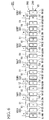
- FIG. 4 is a development view of the stator
- FIG. 5 is a wiring connection diagram of the small coils.
- each of the teeth 64 and the small coils 81 wound to these teeth 64 are numbered and the explanation will be given (the same applies to the following embodiments).
- terminals of the small coils 81 adjacent in the circumferential direction are connected to each other by a crimp-type terminal 51. Also, at each crimp-type terminal 51 described below, an end of harness 50 is connected.
- the harness 50 for one-phase is configured by two wires, and thereby, the number of the wires of the harnesses 50 is six wires in total. That is, the harnesses 50 are configured by U-phase harnesses 50U1, 50U2 (two wires), V-phase harnesses 50V1, 50V2 (two wires), and W-phase harnesses 50W1, 50W2 (two wires).
- the other terminal 81b of the small coil 81 of the No.1 tooth 64 is connected to a terminal 81a of a small coil 81 of the No. 12 tooth 64 arranged on the opposite side of the other terminal 81b, by the crimp-type terminal 51.
- two terminals 81a, 81b extending from each of the small coils 81 formed to the No. 4, 5, 8, 9 and 12 teeth 64 are configured the same as the two terminals 81a, 81b extending from the small coil 81 of the No. 1 tooth 64.
- the harnesses 50U1 to 50W2 of each phase configured by two wires are configured such that the harnesses 50U1 to 50W2 having the same phase to each other are connected to the same terminals (not shown) of an external power supply.
- two small coils 81 are connected in series to form a small coil group 82.
- two small coil groups 82 are connected in parallel to form three units of the phase coil 83, and these phase coils 83 form a delta connection.
- the number of series connections of the small coils 81 (thereby forming a small coil group 82) is defined as TN
- the number of the split cores 61 (teeth 64) is defined as CN
- one end of the harnesses 50U1 to 50W2 of each phase is connected to the terminal of each of the small coils 81 via the crimp-type terminal 51, and the other end of these harnesses extends to the outside of the stator casing 2 via the outlet port 21 formed in the stator housing 2.
- the harness 50V2 of the V-phase and the harness 50W1 of the W-phase are connected to the two crimp-type terminals 51 arranged at the position farthest from the outlet port 21 formed at the stator housing 2.
- These harnesses i.e., the harness 50V2 of the V-phase and the harness 50W1 of the W-phase, are routed to intersect with each other in the stator housing 2.
- the harness 50V2 of the V-phase and the harness 50W1 of the W-phase are not routed on the shortest path to the outlet port 21 of the stator housing 2, but they are routed to bypass around the rotor 4.
- the harness 50V2 of the V-phase and the harness 50W1 of the W-phase intersect with each other at the opposite side of the outlet port 21 with the rotation shaft 6 being set as a center.
- harnesses 50 other than the harness 50V2 of the V-phase and the harness 50W1 of the W-phase are routed on the shortest path to the outlet port 21 of the stator housing 2.
- the rotor 4 includes the rotation shaft 6 one end of which is supported rotatably by a bearing 5 of the stator housing 2, a rotor core 41 fixed to the rotation shaft 6 by fitting from outside the rotation shaft 6, and a magnet 13 arranged along the circumferential direction in the rotor core 41.
- the rotor core 41 is formed by laminating in the axial direction a plurality of flat rolled magnetic steel sheets and strips formed in a substantially disk shape, and a press-fitting hole 43 which can press fit the rotation shaft 6 to the center in the radial direction is formed in the rotor core 41.
- a thickness of the rotor core 41 in the axial direction is set substantially the same as the thickness of the stator core 10 in the axial direction. Furthermore, in the outer circumferential part of the rotor core 41, ten slits 44 penetrated in the axial direction are formed at equal intervals in the circumferential direction. The magnets 13 are inserted into these slits 44 and fixed therein.
- the magnet 13 is a permanent magnet made of neodymium or the like having a segment type formed in a blockish shape, and arranged in the slit 44 so that the magnetic poles are changed sequentially in the circumferential direction.
- the length in the axial direction of the magnet 13 is set so as to substantially match the length in the axial direction of the rotor core 41.
- the number of magnets 13, that is, the number of the magnetic poles is defined as P
- the number of slots formed between each of the teeth 64 is defined as S
- the number of the magnetic poles P is set to "10"
- the number of slots S is set to "12" because the number of teeth 64 is 12.
- the cover 7 provided to cover the opening 2a of the stator housing 2 is formed in a shallow cylindrical shape having a bottom portion.
- the cover 7 is arranged so that an opening 7a facing the stator housing 2 side.
- the boss 7c protrudes outward in the axial direction at the center in the radial direction.
- a bearing 22 rotatably supporting the other end of the rotation shaft 6 is pressed fit into the boss 7c.
- An outer circumferential portion side of the bottom 7b of the cover 7 is formed so as to swell outward in the axial direction, and the connection part between each small coil 81 and each harness 50 is prevented from bending by force. Furthermore, in the cylindrical portion 7d of the cover 7, an outlet port 23 is formed at a portion corresponding to the outlet port 21 of the stator housing 2. The other end of each of the harnesses 50 extends from an opening 24 surrounded by the outlet port 21 of the stator housing 2 and the outlet port 23 of the cover 7.
- the brushless motor 1 is adapted to generate a magnetic field in the stator core 10 by supplying a current supplied from the external power supply to each phase coil 83 via each harness 50. Then, the rotor 4 rotates by the magnetic suction force and repulsive force between the magnetic field and the magnet 13.
- the harness 50 is connected to one end of each phase coil 83 along with connecting these three units of the phase coil 83 in a delta connection, and the other end thereof extends to the outside of the stator housing 2 (refer to FIG.
- the first embodiment can complete the wiring connection of the phase coils 83 without using a bus-bar unit like the prior art, and production costs can be reduced.
- the connection points between the harnesses 50 and each of the small coils 81 can be minimized, and complication of wiring-connection workability can be prevented.
- two terminals extending from each of the small coils 81 formed to the No. 1, 4, 5, 8, 9, and 12 teeth 64, are intersected, and these two terminals are respectively connected to the terminals of the small coils 81 formed to other teeth 64 arranged on the opposite side of each of these terminals, by the crimp-type terminal 51.
- the harnesses 50U1 to 50W2 of each phase can be configured by two wires.
- the harness 50V2 of the V-phase and the harness 50W1 of the W-phase are connected to the two crimp-type terminal 51 arranged at the position farthest from the outlet port 21 formed at the stator housing 2.
- These harnesses which are the harness 50V2 of the V-phase and the harness 50W1 of the W-phase, are routed to intersect with each other in the stator housing 2.
- a portion of overlapping (an overlapping portion) of the harnesses 50 routed inside the stator housing 2 can be distributed. That is, the overlapping portion of the harnesses 50 is not concentrated, and the harnesses 50 routed therein can be prevented from becoming bulky. Accordingly, whole of the brushless motor 1 can reliably achieve downsizing.
- FIG. 6 and FIG. 7 The explanation has been made by numbering the same reference numbers to the same illustrative embodiment of the first embodiment (the same applies to the following embodiments).
- FIG. 6 is a development view of a stator according to the second embodiment
- FIG. 5 is a connection diagram of a small coil according to the second embodiment.
- the brushless motor 201 is used for, for example, motorcycles, the basic structure such that the brushless motor 201 includes a stator 203, a rotor (not shown in the second embodiment) provided to be rotatable with respect to the stator 203, and a harness 50 an end of which is connected to a winding wire 12 wound to the stator 203, and which is for supplying a current to the winding wire 12 is the same as the first embodiment.
- a stator core 210 of the stator 203 has the form of a split core which can be divided in the circumferential direction, and the winding wire 12 is wound to teeth 64 of the split core 61 by a concentrated winding system (the same applies to the following embodiments).
- the first embodiment described above and the second embodiment is different in that the stator core 210 of the stator 203 in the second embodiment is configured by eighteen pieces of the split cores 61, whereas the stator core 10 of the stator 3 in the first embodiment is configured by twelve pieces of the split cores 61.
- the number of the magnetic poles P is set to "16". That is, in the second embodiment, the number of slots S (the number of teeth 64) is set to "18" and the number of the magnetic poles P is set to "16". Thus, the number of slots S and the number of the magnetic poles P satisfy the expression (2) of the aforementioned first embodiment.
- the small coil 81 formed by winding the winding wire 12 to each of the teeth 64 is connected as follows.
- the harnesses 50 includes U-phase harnesses 50U1, 50U2 (two wires), V-phase harnesses 50V1, 50V2 (two wires), and W-phase harnesses 50W1, 50W2 (two wires).
- the terminals of the small coils 81 adjacent in the circumferential direction are connected to each other by a crimp-type terminal 51.
- each of the harnesses 50 is connected to the following crimp-type terminal 51.
- three small coils 81 are connected in series to form a small coil group 82.
- two small coil groups 82 are connected in parallel to form three units of the phase coil 83, and these phase coils 83 form a delta connection.
- the number of series connections of the small coils 81 (thereby forming a small coil group 82) is defined as TN
- the number of the split cores 61 (teeth 64) is defined as CN
- the number of series connections TN and the number of the split cores 61 CN are set to satisfy the expression (1) of the aforementioned first embodiment.
- the above second embodiment can obtain the same effects as the aforementioned first embodiment.
- FIG. 8 is a development view of a stator according to the third embodiment
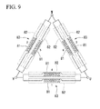
- FIG. 9 is a connection diagram of a small coil according to the third embodiment.
- the aforementioned first embodiment and the third embodiment is different in that the stator core 310 of the stator 303 in the third embodiment of the brushless motor 301 is configured by six pieces of the split cores 61, whereas the stator core 10 of the stator 3 in the first embodiment is configured by twelve pieces of the split cores 61.
- the number of the magnetic poles P is set to "4". That is, in the third embodiment, the number of slots S (the number of teeth 64) is set to "6" and the number of the magnetic poles P is set to "4". Thus, the number of slots S and the number of the magnetic poles P satisfy the expression (2) of the aforementioned first embodiment.
- the small coil 81 formed by winding the winding wire 12 to each of the teeth 64 is connected as follows.
- the harnesses 50 includes U-phase harnesses 50U1, 50U2 (two wires), V-phase harnesses 50V1, 50V2 (two wires), and W-phase harnesses 50W1, 50W2 (two wires).
- the terminals of the small coils 81 adjacent in the circumferential direction are connected to each other by a crimp-type terminal 51, and one end of the harness 50 is connected.
- two terminals extending from each of the small coils 81 formed to each of the teeth 64 intersect with each other. These two terminals are respectively connected to the terminals of the small coils 81 of other teeth 64 arranged on the opposite side of each of these terminals, by the crimp-type terminal 51.
- phase coil 83 connecting two small coils 81 in parallel is formed, and these phase coils 83 form a delta connection.
- a single small coil group 82 is formed of a single small coil 81, and two units of this small coil group 82 are connected in parallel to form the phase coil 83.
- the number of series connections of the small coils 81 (thereby forming a small coil group 82) is defined as TN
- the number of the split cores 61 (teeth 64) is defined as CN
- the number of series connections TN and the number of the split cores 61 CN are set to satisfy the expression (1) of the aforementioned first embodiment.
- the above third embodiment can obtain the same effects as the aforementioned first embodiment.
- the present invention is not limited to the configuration of the above described embodiment, and it includes various changes made to the above embodiment without departing from the spirit thereof.
- the above embodiment was explained in a case that the brushless motor 1 is used for motorcycles. However, it is not limited thereto, and it is possible to apply the structure of the brushless motor 1 of the embodiment to a various electric motors.
- the above embodiment was explained in a case that the terminals of the small coils 81 adjacent in the circumferential direction are connected to each other by a crimp-type terminal 51.
- it is not limited thereto, and it may be a structure which can electrically connect the terminals of the small coils 81 to each other.
- it may be configured to connect small coils 81 adjacent to each other in a manner such that the small coils 81 are formed in a continuous way by a single winding wire 12.
- the coils for each phase can connect without using a bus-bar unit as in the prior art, production costs can be reduced.
- the terminals of the small coils adjacent in the circumferential direction are connected to each other to form a small coil group in which two or three small coils are connected in series, and furthermore, since two small coil groups are electrically connected in parallel to form each of the phase coils configured by three phases, i.e., U-phase, V-phase and W-phase, the connection points between the harnesses and each small coil can be minimum, and complication of wiring-connection workability can be prevented.
Landscapes
- Engineering & Computer Science (AREA)
- Power Engineering (AREA)
- Windings For Motors And Generators (AREA)
- Iron Core Of Rotating Electric Machines (AREA)
- Insulation, Fastening Of Motor, Generator Windings (AREA)
- Motor Or Generator Frames (AREA)
Applications Claiming Priority (2)
| Application Number | Priority Date | Filing Date | Title |
|---|---|---|---|
| JP2012259868A JP6068953B2 (ja) | 2012-11-28 | 2012-11-28 | 電動モータ |
| PCT/JP2013/077512 WO2014083947A1 (fr) | 2012-11-28 | 2013-10-09 | Moteur électrique |
Publications (2)
| Publication Number | Publication Date |
|---|---|
| EP2928048A1 true EP2928048A1 (fr) | 2015-10-07 |
| EP2928048A4 EP2928048A4 (fr) | 2016-08-24 |
Family
ID=50827593
Family Applications (1)
| Application Number | Title | Priority Date | Filing Date |
|---|---|---|---|
| EP13857849.7A Withdrawn EP2928048A4 (fr) | 2012-11-28 | 2013-10-09 | Moteur électrique |
Country Status (5)
| Country | Link |
|---|---|
| EP (1) | EP2928048A4 (fr) |
| JP (1) | JP6068953B2 (fr) |
| CN (1) | CN104205577B8 (fr) |
| IN (1) | IN2014DN08478A (fr) |
| WO (1) | WO2014083947A1 (fr) |
Cited By (6)
| Publication number | Priority date | Publication date | Assignee | Title |
|---|---|---|---|---|
| DE102016223003A1 (de) * | 2016-04-29 | 2017-11-02 | Robert Bosch Gmbh | Stator für eine elektrische Maschine sowie eine elektrische Maschine mit solch einem Stator |
| EP3252928A1 (fr) * | 2016-06-03 | 2017-12-06 | Siemens Aktiengesellschaft | Ensemble stator avec un agencement de câblage de câbles, générateur et éolienne dotée d'un tel ensemble stator |
| EP3493375A1 (fr) * | 2017-12-01 | 2019-06-05 | Siemens Gamesa Renewable Energy A/S | Ensemble stator avec agencements de câblage flexible, générateur et éolienne dotée d'un tel ensemble stator |
| EP3370326A4 (fr) * | 2015-10-28 | 2019-06-26 | Mitsubishi Electric Corporation | Machine électrique tournante |
| EP3457531A3 (fr) * | 2017-09-18 | 2019-08-07 | IFP Energies nouvelles | Machine électrique comprenant un stator muni d'un manchon tubulaire interne pour le passage d'un fluide de refroidissement |
| DE102024106874A1 (de) * | 2024-03-11 | 2025-09-11 | Minebea Mitsumi Inc. | Elektromotor |
Families Citing this family (11)
| Publication number | Priority date | Publication date | Assignee | Title |
|---|---|---|---|---|
| EP2978105A1 (fr) * | 2014-07-22 | 2016-01-27 | Mmt Ag | Moteur électrique pas-à-pas |
| WO2017046954A1 (fr) * | 2015-09-18 | 2017-03-23 | 三菱電機株式会社 | Procédé de fabrication de machine électrique tournante, stator pour machine électrique tournante, et machine électrique tournante équipée d'un stator |
| JP6844614B2 (ja) * | 2016-03-30 | 2021-03-17 | 日本電産株式会社 | モータ |
| JP6851735B2 (ja) * | 2016-07-08 | 2021-03-31 | 株式会社マキタ | 電動工具 |
| WO2018020650A1 (fr) * | 2016-07-29 | 2018-02-01 | 日本電産株式会社 | Stator et moteur |
| FR3054747B1 (fr) * | 2016-07-29 | 2019-07-12 | Valeo Equipements Electriques Moteur | Machine electrique tournante munie d'un bobinage a configuration amelioree |
| CN106877531A (zh) * | 2017-03-31 | 2017-06-20 | 广东威灵电机制造有限公司 | 电机定子及电机 |
| EP4007127B1 (fr) * | 2019-07-31 | 2026-05-06 | Toshiba Carrier Corporation | Moteur électrique, compresseur, dispositif de circuit de réfrigération, et procédé de fabrication d'un moteur électrique |
| CN115693989A (zh) * | 2021-07-26 | 2023-02-03 | 莱克电气股份有限公司 | 一种定子、电机、家用电器及园林设备 |
| JP2024039256A (ja) * | 2022-09-09 | 2024-03-22 | ミネベアミツミ株式会社 | ステータ及びモータ |
| CN117175821B (zh) * | 2023-11-02 | 2024-01-26 | 博格华纳汽车零部件(武汉)有限公司 | 一种72槽6极3支路发夹式扁线电枢绕组及电机 |
Family Cites Families (10)
| Publication number | Priority date | Publication date | Assignee | Title |
|---|---|---|---|---|
| US6824432B2 (en) * | 2000-10-26 | 2004-11-30 | Fanuc Ltd. | Terminal unit for electric motor |
| FR2823613B1 (fr) * | 2001-04-17 | 2008-07-18 | Leroy Somer Moteurs | Bobine pour machine electrique tournante |
| EP1722464B1 (fr) * | 2005-05-11 | 2019-05-08 | Brose Fahrzeugteile GmbH & Co. KG, Würzburg | Méthode pour bobiner un stator de moteur électrique et stator de moteur électrique |
| EP2082472B1 (fr) * | 2006-10-14 | 2012-10-10 | ebm-papst St. Georgen GmbH & Co. KG | Moteur électrique |
| JP5176475B2 (ja) * | 2007-10-19 | 2013-04-03 | 株式会社ジェイテクト | モータおよび電気式動力舵取装置 |
| EP2256906A4 (fr) * | 2007-11-09 | 2014-10-15 | Mitsubishi Electric Corp | Stator pour machine électrique tournante et son procédé de fabrication |
| JP2009148020A (ja) * | 2007-12-12 | 2009-07-02 | Mitsuba Corp | 永久磁石式の交流発電機 |
| JP5460095B2 (ja) | 2009-03-26 | 2014-04-02 | 株式会社ミツバ | ブラシレスモータ |
| CN201504164U (zh) * | 2009-09-28 | 2010-06-09 | 永济新时速电机电器有限责任公司 | 双边引出线结构异步电动机 |
| DE102010042677A1 (de) * | 2010-08-17 | 2012-02-23 | Robert Bosch Gmbh | Elektrische Maschine |
-
2012
- 2012-11-28 JP JP2012259868A patent/JP6068953B2/ja not_active Expired - Fee Related
-
2013
- 2013-10-09 IN IN8478DEN2014 patent/IN2014DN08478A/en unknown
- 2013-10-09 EP EP13857849.7A patent/EP2928048A4/fr not_active Withdrawn
- 2013-10-09 CN CN201380018929.0A patent/CN104205577B8/zh not_active Expired - Fee Related
- 2013-10-09 WO PCT/JP2013/077512 patent/WO2014083947A1/fr not_active Ceased
Cited By (9)
| Publication number | Priority date | Publication date | Assignee | Title |
|---|---|---|---|---|
| EP3370326A4 (fr) * | 2015-10-28 | 2019-06-26 | Mitsubishi Electric Corporation | Machine électrique tournante |
| US10404124B2 (en) | 2015-10-28 | 2019-09-03 | Mitsubishi Electric Corporation | Rotary electric machine |
| DE102016223003A1 (de) * | 2016-04-29 | 2017-11-02 | Robert Bosch Gmbh | Stator für eine elektrische Maschine sowie eine elektrische Maschine mit solch einem Stator |
| EP3252928A1 (fr) * | 2016-06-03 | 2017-12-06 | Siemens Aktiengesellschaft | Ensemble stator avec un agencement de câblage de câbles, générateur et éolienne dotée d'un tel ensemble stator |
| US10389210B2 (en) | 2016-06-03 | 2019-08-20 | Siemens Gamesa Renewable Energy A/S | Stator assembly with a cable wiring arrangement, generator and wind turbine with such a stator assembly |
| EP3457531A3 (fr) * | 2017-09-18 | 2019-08-07 | IFP Energies nouvelles | Machine électrique comprenant un stator muni d'un manchon tubulaire interne pour le passage d'un fluide de refroidissement |
| EP3493375A1 (fr) * | 2017-12-01 | 2019-06-05 | Siemens Gamesa Renewable Energy A/S | Ensemble stator avec agencements de câblage flexible, générateur et éolienne dotée d'un tel ensemble stator |
| WO2019106167A1 (fr) * | 2017-12-01 | 2019-06-06 | Siemens Gamesa Renewable Energy A/S | Ensemble stator à agencements de câblage flexibles, générateur et éolienne ayant un tel ensemble stator |
| DE102024106874A1 (de) * | 2024-03-11 | 2025-09-11 | Minebea Mitsumi Inc. | Elektromotor |
Also Published As
| Publication number | Publication date |
|---|---|
| CN104205577B (zh) | 2016-11-30 |
| WO2014083947A1 (fr) | 2014-06-05 |
| EP2928048A4 (fr) | 2016-08-24 |
| JP6068953B2 (ja) | 2017-01-25 |
| IN2014DN08478A (fr) | 2015-05-08 |
| JP2014107983A (ja) | 2014-06-09 |
| CN104205577A (zh) | 2014-12-10 |
| CN104205577B8 (zh) | 2017-04-19 |
Similar Documents
| Publication | Publication Date | Title |
|---|---|---|
| EP2928048A1 (fr) | Moteur électrique | |
| JP5070248B2 (ja) | 回転電機とその製造方法 | |
| JP4404199B2 (ja) | 同期電動機 | |
| JP6053001B2 (ja) | バスバーユニット | |
| EP3176912B1 (fr) | Stator et machine tournante | |
| JP4331231B2 (ja) | ステータおよび回転電機 | |
| JP6844614B2 (ja) | モータ | |
| US20130257200A1 (en) | In-Vehicle Motor and Electric Power Steering Device Including the Same | |
| US9362796B2 (en) | Electricity collection and distribution ring and electric motor | |
| JP6706583B2 (ja) | ブラシレスモータ | |
| US10840656B2 (en) | Bus bar unit and rotary electric machine having the same | |
| US20130049515A1 (en) | Stator for rotary electric machine, and rotary electric machine | |
| CN112564361B (zh) | 定子 | |
| JP2013223293A (ja) | ブラシレスモータ | |
| JP2019017211A (ja) | ブラシレスモータ及び電動パワーステアリング装置 | |
| EP2536004B1 (fr) | Stator de machine électrique tournante, et machine électrique tournante | |
| JP2007174869A (ja) | インシュレータ、ステータアセンブリ、セグメントステータ、及び回転電機用ステータ | |
| JP6103558B1 (ja) | 回転電機 | |
| CN104685768A (zh) | 单转子式电动机 | |
| US11114913B2 (en) | Rotating electric machine | |
| CN211930351U (zh) | 定子以及无刷马达 | |
| JP2019103354A (ja) | 回転電機 | |
| JP2013223295A (ja) | 回転電機 | |
| JP2014192997A (ja) | 電動モータ | |
| JP6488100B2 (ja) | 電動モータ |
Legal Events
| Date | Code | Title | Description |
|---|---|---|---|
| PUAI | Public reference made under article 153(3) epc to a published international application that has entered the european phase |
Free format text: ORIGINAL CODE: 0009012 |
|
| 17P | Request for examination filed |
Effective date: 20141010 |
|
| AK | Designated contracting states |
Kind code of ref document: A1 Designated state(s): AL AT BE BG CH CY CZ DE DK EE ES FI FR GB GR HR HU IE IS IT LI LT LU LV MC MK MT NL NO PL PT RO RS SE SI SK SM TR |
|
| AX | Request for extension of the european patent |
Extension state: BA ME |
|
| DAX | Request for extension of the european patent (deleted) | ||
| RA4 | Supplementary search report drawn up and despatched (corrected) |
Effective date: 20160721 |
|
| RIC1 | Information provided on ipc code assigned before grant |
Ipc: H02K 3/18 20060101ALI20160715BHEP Ipc: H02K 1/18 20060101ALI20160715BHEP Ipc: H02K 3/52 20060101ALI20160715BHEP Ipc: H02K 3/28 20060101ALI20160715BHEP Ipc: H02K 1/14 20060101ALI20160715BHEP Ipc: H02K 5/22 20060101ALI20160715BHEP Ipc: H02K 3/50 20060101AFI20160715BHEP |
|
| RIC1 | Information provided on ipc code assigned before grant |
Ipc: H02K 1/18 20060101ALI20191120BHEP Ipc: H02K 1/14 20060101ALI20191120BHEP Ipc: H02K 3/28 20060101ALI20191120BHEP Ipc: H02K 3/50 20060101AFI20191120BHEP Ipc: H02K 3/52 20060101ALI20191120BHEP Ipc: H02K 5/22 20060101ALI20191120BHEP Ipc: H02K 3/18 20060101ALI20191120BHEP |
|
| GRAP | Despatch of communication of intention to grant a patent |
Free format text: ORIGINAL CODE: EPIDOSNIGR1 |
|
| STAA | Information on the status of an ep patent application or granted ep patent |
Free format text: STATUS: GRANT OF PATENT IS INTENDED |
|
| RAP1 | Party data changed (applicant data changed or rights of an application transferred) |
Owner name: MITSUBA CORPORATION |
|
| INTG | Intention to grant announced |
Effective date: 20200116 |
|
| STAA | Information on the status of an ep patent application or granted ep patent |
Free format text: STATUS: THE APPLICATION IS DEEMED TO BE WITHDRAWN |
|
| 18D | Application deemed to be withdrawn |
Effective date: 20200603 |