EP2928050A1 - Moteur, dispositif de commande et dispositif d'entraînement de moteur - Google Patents
Moteur, dispositif de commande et dispositif d'entraînement de moteur Download PDFInfo
- Publication number
- EP2928050A1 EP2928050A1 EP13858744.9A EP13858744A EP2928050A1 EP 2928050 A1 EP2928050 A1 EP 2928050A1 EP 13858744 A EP13858744 A EP 13858744A EP 2928050 A1 EP2928050 A1 EP 2928050A1
- Authority
- EP
- European Patent Office
- Prior art keywords
- motor
- temperature
- internal air
- calculation unit
- coil
- Prior art date
- Legal status (The legal status is an assumption and is not a legal conclusion. Google has not performed a legal analysis and makes no representation as to the accuracy of the status listed.)
- Withdrawn
Links
Images



Classifications
-
- H—ELECTRICITY
- H02—GENERATION; CONVERSION OR DISTRIBUTION OF ELECTRIC POWER
- H02P—CONTROL OR REGULATION OF ELECTRIC MOTORS, ELECTRIC GENERATORS OR DYNAMO-ELECTRIC CONVERTERS; CONTROLLING TRANSFORMERS, REACTORS OR CHOKE COILS
- H02P29/00—Arrangements for regulating or controlling electric motors, appropriate for both AC and DC motors
- H02P29/60—Controlling or determining the temperature of the motor or of the drive
- H02P29/66—Controlling or determining the temperature of the rotor
- H02P29/662—Controlling or determining the temperature of the rotor the rotor having permanent magnets
-
- B—PERFORMING OPERATIONS; TRANSPORTING
- B60—VEHICLES IN GENERAL
- B60L—PROPULSION OF ELECTRICALLY-PROPELLED VEHICLES; SUPPLYING ELECTRIC POWER FOR AUXILIARY EQUIPMENT OF ELECTRICALLY-PROPELLED VEHICLES; ELECTRODYNAMIC BRAKE SYSTEMS FOR VEHICLES IN GENERAL; MAGNETIC SUSPENSION OR LEVITATION FOR VEHICLES; MONITORING OPERATING VARIABLES OF ELECTRICALLY-PROPELLED VEHICLES; ELECTRIC SAFETY DEVICES FOR ELECTRICALLY-PROPELLED VEHICLES
- B60L15/00—Methods, circuits, or devices for controlling the traction-motor speed of electrically-propelled vehicles
- B60L15/20—Methods, circuits, or devices for controlling the traction-motor speed of electrically-propelled vehicles for control of the vehicle or its driving motor to achieve a desired performance, e.g. speed, torque, programmed variation of speed
-
- B—PERFORMING OPERATIONS; TRANSPORTING
- B60—VEHICLES IN GENERAL
- B60L—PROPULSION OF ELECTRICALLY-PROPELLED VEHICLES; SUPPLYING ELECTRIC POWER FOR AUXILIARY EQUIPMENT OF ELECTRICALLY-PROPELLED VEHICLES; ELECTRODYNAMIC BRAKE SYSTEMS FOR VEHICLES IN GENERAL; MAGNETIC SUSPENSION OR LEVITATION FOR VEHICLES; MONITORING OPERATING VARIABLES OF ELECTRICALLY-PROPELLED VEHICLES; ELECTRIC SAFETY DEVICES FOR ELECTRICALLY-PROPELLED VEHICLES
- B60L3/00—Electric devices on electrically-propelled vehicles for safety purposes; Monitoring operating variables, e.g. speed, deceleration or energy consumption
- B60L3/12—Recording operating variables ; Monitoring of operating variables
-
- H—ELECTRICITY
- H02—GENERATION; CONVERSION OR DISTRIBUTION OF ELECTRIC POWER
- H02K—DYNAMO-ELECTRIC MACHINES
- H02K11/00—Structural association of dynamo-electric machines with electric components or with devices for shielding, monitoring or protection
- H02K11/20—Structural association of dynamo-electric machines with electric components or with devices for shielding, monitoring or protection for measuring, monitoring, testing, protecting or switching
- H02K11/25—Devices for sensing temperature, or actuated thereby
-
- H—ELECTRICITY
- H02—GENERATION; CONVERSION OR DISTRIBUTION OF ELECTRIC POWER
- H02K—DYNAMO-ELECTRIC MACHINES
- H02K21/00—Synchronous motors having permanent magnets; Synchronous generators having permanent magnets
- H02K21/12—Synchronous motors having permanent magnets; Synchronous generators having permanent magnets with stationary armatures and rotating magnets
- H02K21/14—Synchronous motors having permanent magnets; Synchronous generators having permanent magnets with stationary armatures and rotating magnets with magnets rotating within the armatures
-
- B—PERFORMING OPERATIONS; TRANSPORTING
- B60—VEHICLES IN GENERAL
- B60L—PROPULSION OF ELECTRICALLY-PROPELLED VEHICLES; SUPPLYING ELECTRIC POWER FOR AUXILIARY EQUIPMENT OF ELECTRICALLY-PROPELLED VEHICLES; ELECTRODYNAMIC BRAKE SYSTEMS FOR VEHICLES IN GENERAL; MAGNETIC SUSPENSION OR LEVITATION FOR VEHICLES; MONITORING OPERATING VARIABLES OF ELECTRICALLY-PROPELLED VEHICLES; ELECTRIC SAFETY DEVICES FOR ELECTRICALLY-PROPELLED VEHICLES
- B60L2220/00—Electrical machine types; Structures or applications thereof
- B60L2220/50—Structural details of electrical machines
-
- B—PERFORMING OPERATIONS; TRANSPORTING
- B60—VEHICLES IN GENERAL
- B60L—PROPULSION OF ELECTRICALLY-PROPELLED VEHICLES; SUPPLYING ELECTRIC POWER FOR AUXILIARY EQUIPMENT OF ELECTRICALLY-PROPELLED VEHICLES; ELECTRODYNAMIC BRAKE SYSTEMS FOR VEHICLES IN GENERAL; MAGNETIC SUSPENSION OR LEVITATION FOR VEHICLES; MONITORING OPERATING VARIABLES OF ELECTRICALLY-PROPELLED VEHICLES; ELECTRIC SAFETY DEVICES FOR ELECTRICALLY-PROPELLED VEHICLES
- B60L2240/00—Control parameters of input or output; Target parameters
- B60L2240/10—Vehicle control parameters
- B60L2240/12—Speed
-
- B—PERFORMING OPERATIONS; TRANSPORTING
- B60—VEHICLES IN GENERAL
- B60L—PROPULSION OF ELECTRICALLY-PROPELLED VEHICLES; SUPPLYING ELECTRIC POWER FOR AUXILIARY EQUIPMENT OF ELECTRICALLY-PROPELLED VEHICLES; ELECTRODYNAMIC BRAKE SYSTEMS FOR VEHICLES IN GENERAL; MAGNETIC SUSPENSION OR LEVITATION FOR VEHICLES; MONITORING OPERATING VARIABLES OF ELECTRICALLY-PROPELLED VEHICLES; ELECTRIC SAFETY DEVICES FOR ELECTRICALLY-PROPELLED VEHICLES
- B60L2240/00—Control parameters of input or output; Target parameters
- B60L2240/10—Vehicle control parameters
- B60L2240/14—Acceleration
- B60L2240/16—Acceleration longitudinal
-
- B—PERFORMING OPERATIONS; TRANSPORTING
- B60—VEHICLES IN GENERAL
- B60L—PROPULSION OF ELECTRICALLY-PROPELLED VEHICLES; SUPPLYING ELECTRIC POWER FOR AUXILIARY EQUIPMENT OF ELECTRICALLY-PROPELLED VEHICLES; ELECTRODYNAMIC BRAKE SYSTEMS FOR VEHICLES IN GENERAL; MAGNETIC SUSPENSION OR LEVITATION FOR VEHICLES; MONITORING OPERATING VARIABLES OF ELECTRICALLY-PROPELLED VEHICLES; ELECTRIC SAFETY DEVICES FOR ELECTRICALLY-PROPELLED VEHICLES
- B60L2240/00—Control parameters of input or output; Target parameters
- B60L2240/10—Vehicle control parameters
- B60L2240/36—Temperature of vehicle components or parts
-
- B—PERFORMING OPERATIONS; TRANSPORTING
- B60—VEHICLES IN GENERAL
- B60L—PROPULSION OF ELECTRICALLY-PROPELLED VEHICLES; SUPPLYING ELECTRIC POWER FOR AUXILIARY EQUIPMENT OF ELECTRICALLY-PROPELLED VEHICLES; ELECTRODYNAMIC BRAKE SYSTEMS FOR VEHICLES IN GENERAL; MAGNETIC SUSPENSION OR LEVITATION FOR VEHICLES; MONITORING OPERATING VARIABLES OF ELECTRICALLY-PROPELLED VEHICLES; ELECTRIC SAFETY DEVICES FOR ELECTRICALLY-PROPELLED VEHICLES
- B60L2240/00—Control parameters of input or output; Target parameters
- B60L2240/40—Drive Train control parameters
- B60L2240/42—Drive Train control parameters related to electric machines
- B60L2240/421—Speed
-
- B—PERFORMING OPERATIONS; TRANSPORTING
- B60—VEHICLES IN GENERAL
- B60L—PROPULSION OF ELECTRICALLY-PROPELLED VEHICLES; SUPPLYING ELECTRIC POWER FOR AUXILIARY EQUIPMENT OF ELECTRICALLY-PROPELLED VEHICLES; ELECTRODYNAMIC BRAKE SYSTEMS FOR VEHICLES IN GENERAL; MAGNETIC SUSPENSION OR LEVITATION FOR VEHICLES; MONITORING OPERATING VARIABLES OF ELECTRICALLY-PROPELLED VEHICLES; ELECTRIC SAFETY DEVICES FOR ELECTRICALLY-PROPELLED VEHICLES
- B60L2240/00—Control parameters of input or output; Target parameters
- B60L2240/40—Drive Train control parameters
- B60L2240/42—Drive Train control parameters related to electric machines
- B60L2240/423—Torque
-
- B—PERFORMING OPERATIONS; TRANSPORTING
- B60—VEHICLES IN GENERAL
- B60L—PROPULSION OF ELECTRICALLY-PROPELLED VEHICLES; SUPPLYING ELECTRIC POWER FOR AUXILIARY EQUIPMENT OF ELECTRICALLY-PROPELLED VEHICLES; ELECTRODYNAMIC BRAKE SYSTEMS FOR VEHICLES IN GENERAL; MAGNETIC SUSPENSION OR LEVITATION FOR VEHICLES; MONITORING OPERATING VARIABLES OF ELECTRICALLY-PROPELLED VEHICLES; ELECTRIC SAFETY DEVICES FOR ELECTRICALLY-PROPELLED VEHICLES
- B60L2240/00—Control parameters of input or output; Target parameters
- B60L2240/40—Drive Train control parameters
- B60L2240/42—Drive Train control parameters related to electric machines
- B60L2240/425—Temperature
-
- Y—GENERAL TAGGING OF NEW TECHNOLOGICAL DEVELOPMENTS; GENERAL TAGGING OF CROSS-SECTIONAL TECHNOLOGIES SPANNING OVER SEVERAL SECTIONS OF THE IPC; TECHNICAL SUBJECTS COVERED BY FORMER USPC CROSS-REFERENCE ART COLLECTIONS [XRACs] AND DIGESTS
- Y02—TECHNOLOGIES OR APPLICATIONS FOR MITIGATION OR ADAPTATION AGAINST CLIMATE CHANGE
- Y02T—CLIMATE CHANGE MITIGATION TECHNOLOGIES RELATED TO TRANSPORTATION
- Y02T10/00—Road transport of goods or passengers
- Y02T10/60—Other road transportation technologies with climate change mitigation effect
- Y02T10/64—Electric machine technologies in electromobility
-
- Y—GENERAL TAGGING OF NEW TECHNOLOGICAL DEVELOPMENTS; GENERAL TAGGING OF CROSS-SECTIONAL TECHNOLOGIES SPANNING OVER SEVERAL SECTIONS OF THE IPC; TECHNICAL SUBJECTS COVERED BY FORMER USPC CROSS-REFERENCE ART COLLECTIONS [XRACs] AND DIGESTS
- Y02—TECHNOLOGIES OR APPLICATIONS FOR MITIGATION OR ADAPTATION AGAINST CLIMATE CHANGE
- Y02T—CLIMATE CHANGE MITIGATION TECHNOLOGIES RELATED TO TRANSPORTATION
- Y02T10/00—Road transport of goods or passengers
- Y02T10/60—Other road transportation technologies with climate change mitigation effect
- Y02T10/72—Electric energy management in electromobility
Definitions
- the present invention relates to a motor drive device for a vehicle driving motor including a stator equipped with a coil and a rotor equipped with a magnet.
- an invention described in PTL 1 is designed to reduce the temperature of a coil or a magnet by reducing torque of a motor when the temperature of the coil or the magnet rises.
- heat generation by the coil is caused by electrical resistance and its heating value varies depending on size of motor torque.
- heat generation by the magnet is caused by changes of a magnetic flux piercing through the magnet and its heating value varies depending on the size of the motor torque and rotational frequency of the motor. Therefore, in a case of the coil, as the size of the motor torque becomes larger, the heating value increases and a coil temperature becomes high. Furthermore, in a case of a magnet 21, when the size of the motor torque becomes larger or the rotational frequency of the motor becomes higher, the heating value increases and a magnet temperature becomes high.
- the cause of heat generation and the operation are different between the coil and the magnet. So, it is impossible to accurately detect the temperature of a rotor equipped with the magnet and prevent an excessive increase of the temperature only by measuring the coil temperature.
- the magnet is embedded in the rotor which is a rotary part, so that it is impossible to measure the temperature by directly attaching a temperature sensor to the rotor.
- the present invention solves the above-described problem and its object is to enable the high-accuracy detection of the temperature of the rotor which has been conventionally difficult.
- the present application includes a plurality of means for solving the above-described problem; and as one example of such means, the present invention is characterized by "including a stator equipped with a coil, a case that secures the stator, a rotor supported by the case via bearings, and an internal air temperature detection unit that detects a temperature of internal air which is air filling the inside of the case.”
- the temperature of the rotor can be detected with a high degree of accuracy. Structures and advantageous effects other than those described above will be made clear by a description of embodiments below.
- Embodiments for carrying out the present invention will be explained below with reference to drawings.
- the embodiments described below explain the present invention by taking, as an example, a case where the present invention is applied to a drive system of an electric car that uses an electric motor as a sole drive source for the car; however, the present invention can also be applied to a control device for electric motor vehicles such as railway vehicles or construction vehicles, and electric motor vehicles using engines, which are internal-combustion engines, and electric motors as vehicle drive sources, that are hybrid cars (passenger cars), freight vehicles such as hybrid trucks, omni-buses such as hybrid buses and the like, for example.
- the following embodiments explain the present invention by taking, as an example, a case where the present invention is applied to a motor including a rotor equipped with a magnet; however, the invention is not limited to this example and the present invention can also be applied to a motor including a rotor which is not equipped with a magnet like an induction motor.
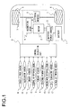
- Fig. 1 is a diagram illustrating the configuration of an electric car (vehicle) drive system (hereinafter referred to as the motor drive device) according to a first embodiment.
- a vehicle includes: a battery 1 that is an energy source for the vehicle; a motor (an electric motor) 2 that electrically drives the vehicle; an inverter power source 3 that converts electric power between the battery 1 and the motor 2; and a control calculation unit 8 that controls the inverter power source 3, a braking device 7, and so on.
- the inverter power source 3 converts direct-current power, which is supplied from the battery 1, into three-phase-alternating-current power by means of pulse width modulation (PWM) and supplies the three-phase-alternating-current power to the motor 2.
- PWM pulse width modulation
- the motor 2 converts electric energy, which is supplied as the three-phase-alternating-current power from the inverter power source 3, into kinetic energy.
- Kinetic power generated as the kinetic energy by the motor 2 is transmitted to a reduction gear 4, the speed is reduced by a gear-type speed reduction mechanism inside this reduction gear 4, and the kinetic power is then transmitted to right and left drive wheels 6 via a differential mechanism 5 and becomes a driving force to drive the vehicle.
- the braking device 7 that puts brakes on the vehicle is provided near the drive wheels 6.
- the braking device 7 includes a hydraulic booster and a hydraulic control force generated by this hydraulic booster presses the drive wheels 6 to generate a frictional force. As a result, the kinetic energy is converted into thermal energy to put the brakes on the vehicle.
- the braking device 7 can reduce a rotational frequency of the motor 2 by putting the brakes on the vehicle.
- the control calculation unit 8 is composed of a CPU, a memory, and so on and controls the motor 2 and the braking device 7 by executing a motor control program described later.
- the control calculation unit 8 can change torque generated by the motor 2 and regenerative electric power to charge the battery 1 by sending a command to the inverter power source 3 and changing the size of the electric current applied to the motor 2 and frequency of an alternating current.
- the control calculation unit 8 can change the braking force generated by the braking device 7 by sending a command to the braking device 7 to change the frictional force generated at the drive wheels 6 (a braking force command described later).
- the control calculation unit 8 is connected to, for example, a vehicle speed sensor 9 which detects a speed of the vehicle, an accelerator sensor 10 which detects an accelerator pedal operation amount (a manipulated variable of an accelerator pedal), a brake sensor 11 which detects a brake pedal operation amount (a manipulated variable of a brake pedal), an external air temperature sensor 12 which detects an external air temperature, a torque sensor 13 which detects torque of the motor 2, a rotational frequency sensor 14 which detects rotational frequency of the motor 2, a cooling water temperature sensor 15 which detects a temperature of cooling water (coolant) 26 described later for the motor 2, a coil temperature sensor 16 which detects a temperature of a coil 24 described later for the motor 2, and an internal air temperature sensor 17 which detects a temperature of internal air 27 described later in the motor 2.
- a vehicle speed sensor 9 which detects a speed of the vehicle
- an accelerator sensor 10 which detects an accelerator pedal operation amount (a manipulated variable of an accelerator pedal)
- a brake sensor 11 which detects a brake pedal operation amount (a manipulated variable
- Fig. 2 is a sectional view illustrating the configuration of the motor 2.
- the motor 2 is an IPM (Interior Permanent Magnet) motor and a magnet 21 is embedded in a rotor 20. Both ends of the rotor 20 are supported by bearings 23 provided at a case 22.
- a stator 25 equipped with a coil 24 is secured to an inner surface of the case 22. When an alternating current is applied to the coil 24 and a rotating magnetic field is thereby generated, the rotor 20 in which the magnet 21 is embedded rotates. As a result, the electric energy supplied to the motor 2 is converted to the kinetic energy.
- the motor 2 generates heat according to an operational status. Accordingly, when the temperature of the motor rises excessively due to the heat generation, there is a possibility that varnish which is applied to the coil 24 may deteriorate. Additionally, the magnet 21 (such as a magnet using rare earth metal) has the property of being irreversibly demagnetized when becoming subject to a large reverse magnetic field at high temperature. Therefore, it is necessary to protect the coil 24 and the magnet 21 against an excessive temperature rise.
- Cooling water 26 flows in the case 22 in order to cool the motor 2.
- the temperature of the motor 2 is reduced by transmitting the heat of the case 22 to this cooling water 26.
- a coil temperature sensor 16 is attached to the coil 24 in order to monitor the temperature of the coil 24.
- an internal air temperature sensor 17 is attached via an internal-air-temperature-detection-point support member 18, which is composed of, for example, a ceramic structure, to the inner surface of the case 22 in order to measure the temperature of internal air 27, which is air filling the inside of the case 22, and have a magnet temperature estimation unit 32, which is included in the control calculation unit 8 described later, refer to the measured temperature.
- the internal air temperature sensor 17 does not directly contact the case 22 by interposing this internal-air-temperature-detection-point support member 18 between them.
- the ceramic structure is used as the internal-air-temperature-detection-point support member 18 in this embodiment; however, instead of this, the internal-air-temperature-detection-point support member 18 may be a signal line for transmitting measurement information of the internal air temperature sensor 17 and this signal line may be extended to separate the internal air temperature sensor 17 from the inner surface of the case 22 for a certain distance, thereby attaching the internal air temperature sensor 17 to the inner surface of the case 22 in a manner such that the internal air temperature sensor 17 does not directly contact the case 22.
- Fig. 3 is a diagram for explaining a heat generating tendency of the coil 24 and indicates the heat generating tendency of the coil 24 (lines L11 to L14) along with a curved line L1 indicative of a rotational frequency and torque property (maximum torque) of the motor 2.
- a vertical axis represents motor torque
- a horizontal axis represents the rotational frequency of the motor
- line L1 which is a bold line represents the maximum torque of the motor 2 at normal temperature.
- the maximum torque L1 represents motor torque which can be output at respective rotational frequencies of the motor and the motor 2 is used in an area inside the maximum torque (area surrounded by line L1).
- Each line L11 to L14 which represents the heat generating tendency is a curved line connecting operating points of the same heating value (heat generation amount).
- the alternating current applied to the coil 24 changes generally according to size (absolute value) of the motor torque. Accordingly, the heating value of the coil 24 increases according to the size of the motor torque and becomes larger in the order of L11 ⁇ L12 ⁇ L13 ⁇ L14. If the motor torque is the same, there is little change in the heating value even if the rotational frequency changes, as can be seen in Fig. 3 .
- L11 to L14 in a negative motor torque range indicate heating values when the motor 2 is in regenerative operation.
- Fig. 4 is a diagram for explaining the heat generating tendency of the magnet 21 and indicates the heat generating tendency (curved lines L21 to L24) of the magnet 21 along with the curved line L1 indicative of the maximum torque of the motor 2.
- a density of the magnetic flux formed by the coil 24 increases according to the size of the motor torque.
- the heating value of the magnet 21 changes according to the size of the motor torque and the rotational frequency of the motor and the shapes of the curved lines L21 to L24 connecting operating points of the same heating value become complicated as shown in Fig. 4 .
- the heating value increases in the order of L21 ⁇ L22 ⁇ L23 ⁇ L24.
- the heating value of the coil 24 changes according to the size of the motor torque ( Fig. 3 ), while the heating value of the magnet 21 changes according to the size of the motor torque and the rotational frequency of the motor as described above ( Fig. 4 ). Accordingly, regarding the coil 24, when the size (absolute value) of the motor torque increases, the heating value increases and the coil temperature becomes high. Furthermore, in a case of the magnet 21, when the size of the motor torque increases or the rotational frequency of the motor increases, the heating value increases and the magnet temperature becomes high.
- the operating points of heavy heat generation are different between the coil 24 and the magnet 21 and an excessive temperature rise of the magnet 21 cannot be prevented only by measuring the temperature of the coil 24 by using the coil temperature sensor 16.
- the coil 24 is provided on the stator 26 which is a non-rotary part, the coil temperature sensor 16 can be easily attached; however, since the magnet 21 is embedded in the rotor 20 which is a rotary part, it is difficult to directly attach the temperature sensor. Therefore, a means for estimating the temperature with a high degree of accuracy without providing the temperature sensor directly on the magnet 21 is required in order to prevent the excessive temperature rise of the magnet 21.
- the control calculation unit 8 is designed to calculate the temperature of the magnet 21 based on the heat generation of the motor 2 calculated from the operational status of the motor 2.
- the temperature of the magnet 21 which is embedded in the rotary part can be estimated without providing the magnet 21 with the sensor for detecting the temperature.
- accuracy to estimate the temperature of the magnet 21 is enhanced by using values detected by the coil temperature sensor 16 and the internal air temperature sensor 17.
- the internal air temperature sensor 17 is attached to the case 22 via the internal-air-temperature-detection-point support member 18 as described above.
- the temperature of the internal air 27 can be measured highly accurately and the temperatures of the rotor 20 and the magnet 21 can be estimated more highly accurately by providing a space between the internal air temperature sensor 17 and the case 22 without having them directly in contact with each other.
- Fig. 5 shows heat flows of the motor 2 in this embodiment.
- flows of heat exist between the case 22 and the external air, the bearings 23, the stator 25, the cooling water 26, and the internal air 27, respectively (heat is transmitted between them respectively).
- the temperatures of the rotor 20 and the magnet 21 are calculated by calculating the heat flows of the motor 2 based on the heat generated by the motor 2, which is calculated from the operational status of the motor 2, the relationship of heat flows of the motor 2 as illustrated in Fig. 5 , a value detected by the external air temperature sensor 13, and a value detected by the cooling water temperature sensor 15.
- the temperature of each part of the motor 2 is determined by inputs and outputs of heat generation by each part of the motor 2, heat transfer at each part of the motor 2, heat radiation from the case 22 to the external air, and heat radiation from the case 22 to the cooling water 26. Under this circumstance, an amount of heat transfer between the respective parts of the motor 2 is determined by temperature differences between the respective parts. Furthermore, an amount of heat radiation from the case 22 to the external air is determined by a temperature difference between the case 22 and the external air. An amount of heat radiation from the case 22 to the cooling water 26 is determined by a temperature difference between the case 22 and the cooling water 26.
- the temperature of each part of the motor 2, that is, the rotor 20 and the magnet 21, can be calculated from the heating value of each part of the motor 2, the temperature of the external air, and the temperature of the cooling water according to the flows of heat in Fig. 5 . Since the heating value of each part of the motor 2 is determined generally by the motor torque and the rotational frequency of the motor, the temperatures of the rotor 20 and the magnet 21 can be estimated by calculating them based on the external air temperature which is actually measured by the external air temperature sensor 13, the cooling water temperature which is actually measured by the cooling water temperature sensor 15, and the motor torque and rotational frequency of the motor, which are the drive status of the motor 2, according to the flows of heat in Fig. 5 . Size and frequency of the aforementioned alternating current may be used as the drive status of the motor 2.
- the estimate accuracy of the magnet temperature 21 is enhanced by using values detected by the coil temperature sensor 16 and the internal air temperature sensor 17.
- the internal air temperature sensor 17 when the internal air temperature sensor 17 is used to measure the temperature of the internal air 27 and there is a difference between the calculated temperature of the internal air 27, which is calculated according to the flows of heat in Fig. 5 , and the temperature measured by the internal air temperature sensor 17, the calculated temperature of each part shown in Fig. 5 is corrected according to this difference.
- the calculated temperature of the internal air 27 is higher than the measured temperature, there is a high possibility that the calculated temperature of each part including the rotor 20 might be also calculated to be higher than its actual temperature. So, the calculated temperature of each part including the rotor 20 is corrected to a lower temperature. As a result, high accuracy of the estimated temperatures of the rotor 20 and the magnet 21 is achieved. Since the rotor 20 directly transmits and receives heat to and from the internal air 27 as shown in Fig. 5 , the temperature of the rotor 20 can be corrected quickly by using the temperature measured by the internal air temperature sensor 17.
- air has lower specific heat than that of metals and the temperature of the air easily changes. So, when the temperature of the rotor 20 changes, the temperature of the internal air 27 changes more quickly than, for example, the stator 25 and the case 22. Therefore, the temperatures of the rotor 20 and the magnet 21 can be corrected quickly by using the internal air temperature sensor 17 which measures the temperature of the internal air 27.
- the temperature of the coil 24 tends to become the highest in the motor 2 and the temperature of the internal air 27 can be easily changed due to the temperature rise of the coil 24. Consequently, when the coil temperature sensor 16 is used to measure the temperature of the coil 24 and there is a difference between the calculated temperature of the coil 24 and the temperature measured by the coil temperature sensor 16, the temperature of each part including the internal air 27 is corrected according to this difference.
- the calculated temperature of the coil 24 is higher than its measured temperature, there is a high possibility that the temperature of the internal air 27 is calculated to be higher than its actual temperature due to the influence of the coil 24. So, the calculated temperature of each part including the internal air 27 is corrected to a lower temperature. As a result, the influence of the coil 24 can be easily separated from among changes of the temperature of the internal air 27 and the temperatures of the rotor 20 and the magnet 21 can be estimated with a high degree of accuracy.
- the excessive temperature rise of the coil 24 and the magnet 21 is prevented by performing different protection operations between a case where the temperature of the coil 24 is high and a case where the temperature of the magnet 21 is high.
- the heating value that is, the motor torque may be limited according to the coil temperature in order to prevent the excessive temperature rise of the coil 24.
- permissible motor torque is comparatively large; and when the coil temperature is equal to or lower than a certain temperature, the motor torque up to the maximum torque in Fig. 3 is permissible.
- the permissible motor torque becomes small.
- the heating value of the magnet 21 changes according to the size (absolute value) of the motor torque and the rotational frequency of the motor and a line having a constant heating value takes a form like each of the lines L21 to L24 shown in Fig. 4 .
- the heating value that is, the motor torque and the rotational frequency of the motor according to the temperature of the magnet 21.
- the heat generated by the magnet 21 increases according to the size (absolute value) of the motor torque and the rotational frequency of the motor as described above. Therefore, when the rotational frequency of the motor is high even if the motor torque is reduced, there is a possibility that temperature of the magnet 21 may increase. For example, when a vehicle is running on a downhill grade, that is, when a load to increase the rotational frequency of the motor is imposed on the rotor 20, a vehicle speed, that is, the rotational frequency of the motor increases even if the motor torque is limited to zero. Under this circumstance, the heat generated by the magnet 21 increases and the magnet temperature continues to increase. Also, if an attempt is made to reduce the rotational frequency of the motor by adjusting the motor torque in this case, it is necessary to increase the motor torque on the regeneration side. In this case as well, the heat generated by the magnet 21 increases.
- the control calculation unit 8 when the rotational frequency of the motor increases even if the control calculation unit 8 sends a command to the inverter power source 3 to make the motor torque zero, the control calculation unit 8 sends a command to the braking device 7 to reduce the vehicle speed, that is, the rotational frequency of the motor. As a result, it is possible to reduce the rotational frequency of the motor and avoid the excessive temperature rise of the magnet 21.
- control calculation unit 8 calculates the temperatures of the rotor 20 and the magnet 21 by calculating the flows of heat at the motor 2 based on the heat generated by the motor 2 which is calculated from the operational status of the motor 2, the heat flow relationship of the motor 2 as show in Fig. 5 , the value detected by the external air temperature sensor 12, and the value detected by the cooling water temperature sensor 15 in the same manner as in a case where the internal air temperature sensor 17 is in normal operation.
- the coil temperature sensor 16 is used to measure the temperature of the coil 24; and when there is a difference between the calculated temperature of the coil 24 and the temperature measured by the coil temperature sensor 16, the temperature of each part including the internal air 27 is corrected according to this difference. As a result, even if the internal air temperature sensor 17 fails, it is possible to continue estimating the temperatures of the rotor 20 and the magnet 21.
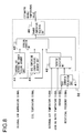
- Fig. 6 is a block diagram illustrating the configuration of the control calculation unit 8 according to the first embodiment.
- Fig. 7 is a flowchart illustrating the operation of the control calculation unit 8 according to the first embodiment. Motor control operation according to the first embodiment will be explained below with reference to Fig. 6 and Fig. 7 .
- a CPU of the control calculation unit 8 achieves motor control blocks illustrated in Fig. 6 in a software form by a microcomputer; and while an ignition key switch (not shown in the drawing) of the vehicle is turned on, the CPU repeats executing a motor control program shown in Fig. 7 .
- the control calculation unit 8 is provided with a torque request calculation unit 30, a braking force request calculation unit 31, a magnet temperature calculation unit 32, a torque limit calculation unit 33, a rotational frequency limit calculation unit 34, a torque command calculation unit 35, and a braking force command calculation unit 36, respectively. The operation of each unit will be explained below.
- step S01 the torque request calculation unit 30 calculates a torque request of the motor 2 based on a vehicle speed signal input from the vehicle speed sensor 9 and an accelerator operation amount signal (a signal according to a step-in quantity of an accelerator pedal) input from the accelerator sensor 10. Specifically speaking, since the accelerator operation amount of the accelerator pedal is proportionate to an output request as the vehicle, the accelerator operation amount is converted into the output request. Then, a driving force request of the vehicle, that is, the torque request of the motor 2 is calculated by dividing that output request by the vehicle speed.
- step S02 the braking force request calculation unit 31 calculates a braking force request of the braking device 7 based on a brake operation amount signal (a signal according to a step-in quantity of a brake pedal) input from the brake sensor 11. Since the brake operation amount of the brake pedal is proportionate to a braking force request as the vehicle, the brake operation amount is converted into the braking force request. Incidentally, the braking force request is converted into a value corresponding to the motor torque and operates to reduce the speed of the vehicle, so that it becomes a negative value.
- a brake operation amount signal a signal according to a step-in quantity of a brake pedal
- step S03 the magnet temperature calculation unit 32 calculates the estimated temperature of the magnet 21 based on a temperature signal of the coil 24 which is input from the coil temperature sensor 16, a temperature signal of the internal air 27 which is input from the internal air temperature sensor 17, a temperature signal of the external air which is input from the external air temperature sensor 12, a temperature signal of the cooling water 26 which is input from the cooling water temperature sensor 15, a torque signal of the motor 2 which is input from the torque sensor 13, and a rotational frequency signal of the motor 2 which is input from the rotational frequency sensor 14.
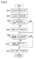
- Fig. 8 is a block diagram illustrating the detailed configuration of the magnet temperature calculation unit 32 and Fig. 9 is a flowchart illustrating the detailed operation of the magnet temperature calculation unit 32.
- the magnet temperature calculation unit 32 is provided with a heat generation calculation unit 41, a temperature calculation unit 42, a coil temperature sensor failure judgment unit 43, an internal air temperature sensor failure judgment unit 44, a temperature correction unit 45, and a magnet temperature selection unit 46, respectively. The operation of each unit will be explained below.
- step S031 the heat generation calculation unit 41 calculates the heating value of each part of the motor 2 (each part such as the rotor 20, the magnet 21, the bearings 23, the coil 24, and the stator 25) based on the motor torque which is input from the torque sensor 13 and the rotational frequency of the motor which is input from the rotational frequency sensor 14.
- the size and frequency of the alternating current which is input from the inverter power source 3 are generally determined relative to the motor torque and the rotational frequency of the motor. Accordingly, the heating value of each part of the motor 2 can be calculated from the motor torque and rotational frequency of the motor which are the drive status of the motor 2.
- step S031 The correspondence relationship between the motor torque and rotational frequency of the motor and the heating value of each part of the motor 2 is stored as a numerical map in a memory included in the control calculation unit 8.
- step S031 the heating value of each part of the motor 2 is calculated by searching this numerical map.
- step S032 the temperature calculation unit 42 calculates a current temperature of each part of the motor 2 based on the external air temperature which is input from the external air temperature sensor 12, the cooling water temperature which is input from the cooling water temperature sensor 15, the heating value of each part of the motor 2 which is calculated by the heat generation calculation unit 41, and a corrected temperature of each part of the motor 2 in the previous step, which is calculated by the temperature correction unit 45 described later.
- the temperature of each part of the motor 2 is determined as described earlier by inputs and outputs of heat generation by each part of the motor 2, heat transfer at each part of the motor 2, heat radiation from the case 22 to the external air, and heat radiation from the case 22 to the cooling water 26. Under this circumstance, an amount of heat transfer between the respective parts of the motor 2 is determined by temperature differences between the respective parts. Furthermore, an amount of heat radiation from the case 22 to the external air is determined by a temperature difference between the case 22 and the external air. An amount of heat radiation from the case 22 to the cooling water 26 is determined by a temperature difference between the case 22 and the cooling water 26. Therefore, the current temperature of each part of the motor 2 can be calculated from the heating value of each part of the motor 2, the external air temperature, the cooling water temperature, and the temperature of each part of the motor 2 in the previous step.
- step S033 the coil temperature sensor failure judgment unit 43 judges whether the coil temperature sensor 16 has failed or not.
- a thermistor is used as the coil temperature sensor 16. When the thermistor is disconnected, electrical resistance increases rapidly. Therefore, a failure caused by the disconnection of the thermistor can be detected by monitoring the electrical resistance. In this way, whether the coil temperature sensor 16 has failed or not is judged. If it is determined that the coil temperature sensor 16 has not failed, NO is determined for the judgment in step S033 and the processing proceeds to step S034. On the other hand, if it is determined in step S033 that the coil temperature sensor 16 has failed, the processing proceeds to step S035.
- step S034 the temperature correction unit 45 compares the estimated temperature of the coil 24 with the measured temperature of the coil 24 which is input from the coil temperature sensor 16, among the temperatures of the respective parts of the motor 2, which are calculated by the temperature calculation unit 42.
- the estimated temperature is higher than the measured temperature, it is determined that the temperature of each part of the motor 2 is calculated to be higher than its actual temperature, and the estimated temperature of each part of the motor 2 is corrected to a lower temperature. If the estimated temperature is lower than the measured temperature, it is determined that the temperature of each part of the motor 2 is calculated to be lower than its actual temperature, and the estimated temperature of each part of the motor 2 is corrected to a higher temperature.
- step S035 the internal air temperature sensor failure judgment unit 44 judges whether the internal air temperature sensor 17 has failed or not.
- the failure judgment of the internal air temperature sensor 17 is also performed in the same manner as the aforementioned failure judgment of the coil temperature sensor 16. Specifically speaking, when a thermistor is used as the internal air temperature sensor 17, its electrical resistance is monitored and a failure caused by disconnection of the thermistor is detected. If it is determined that the internal air temperature sensor 17 has not failed, NO is determined for the judgment in step S035 and the processing proceeds to step S036. On the other hand, if it is determined in step S035 that the internal air temperature sensor 17 has failed, the processing proceeds to step S037.
- step S036 the temperature correction unit 45 compares the estimated temperature of the internal air 27 with the measured temperature of the internal air 27 which is input from the internal air temperature sensor 17, among the estimated temperatures of the respective parts of the motor 2.
- the estimated temperature is higher than the measured temperature, it is determined that the temperature of each part of the motor 2 is calculated to be higher than its actual temperature, and the estimated temperature of each part of the motor 2 is corrected to a lower temperature. If the estimated temperature is lower than the measured temperature, it is determined that the temperature of each part of the motor 2 is calculated to be lower than its actual temperature, and the estimated temperature of each part of the motor 2 is corrected to a higher temperature.
- the magnet temperature selection unit 46 selects the temperature of the magnet 21 from the estimated corrected temperatures of the respected parts of the motor 2, which are calculated by the temperature calculation unit 42 when the coil temperature sensor 16 and the internal air temperature sensor 17 have not failed; and outputs the selected temperature to the torque limit calculation unit 33 and the rotational frequency limit calculation unit 34 described later.
- the torque limit calculation unit 33 calculates a torque limit for protecting the coil 24 and the magnet 21 against the excessive temperature rise based on the temperature of the coil 24 which is input from the coil temperature sensor 16 and the estimated temperature of the magnet 21 which is input from the magnet temperature calculation unit 32.
- the correspondence relationship between the temperature of the coil 24 and the temperature of the magnet 21 and the torque limit is stored as a numerical map in the memory included in the control calculation unit 8.
- the torque limit is calculated by searching this numerical map.
- the torque limit is a positive number, limits the motor torque to the value equal to or less than the torque limit at power running, and limits the motor torque to the value equal to or more than a positive/negative inverted value of the torque limit at regenerating.
- step S05 the rotational frequency limit calculation unit 34 calculates a rotational frequency limit for protecting the magnet 21 against the excessive temperature rise based on the estimated temperature of the magnet 21 which is input from the magnet temperature calculation unit 32.
- the correspondence relationship between the temperature of the magnet 21 and the rotational frequency limit is stored as a numerical map in the memory included in the control calculation unit 8.
- the rotational frequency limit is calculated by searching this numerical map.
- step S06 the torque command calculation unit 35 calculates a torque command to be sent to the inverter power source 3 based on requested torque of the motor 2, which is input from the torque request calculation unit 30, and a torque limit of the motor 2 which is input from the torque limit calculation unit 33.
- the torque limit is a positive number, limits the torque request to the value equal to or less than the torque limit at power running, and limits the torque request to the value equal to or more than a positive/negative inverted value of the torque limit at regenerating.
- the torque request is set as the torque command. If the torque request is equal to or more than the torque limit at power running, the torque limit is set as the torque command.
- the torque request is set as the torque command.
- the torque limit is set as the torque command.
- the torque limit is set as the torque command.
- step S07 the braking force command calculation unit 36 calculates a braking force command to be sent to the braking device 7 based on a braking force request for the braking device 7 which is input from the braking force request calculation unit 31, the torque limit of the motor 2 which is input from the torque limit calculation unit 33, the rotational frequency signal of the motor 2 which is input from the rotational frequency sensor 14, and the rotational frequency limit of the motor 2 which is input from the rotational frequency limit calculation unit 34.
- a command value that makes the rotational frequency of the motor equal to or less than the rotational frequency limit is set as the braking force command.
- the braking force request is set as the braking force command. As a result, it is possible to reduce the rotational frequency of the motor and avoid the excessive temperature rise of the magnet 21.
- the first embodiment is designed as described above so that the magnet temperature calculation unit 32, the torque limit calculation unit 33, and the rotational frequency limit calculation unit 34 are provided as shown in Fig. 6 to estimate the temperature of the magnet 21, output such a torque command as to make the motor torque equal to or less than the torque limit by the torque limit calculation unit 33, and output such a braking force command as to make the rotational frequency of the motor equal to or less than the rotational frequency limit by the rotational frequency limit calculation unit 34. So, it is possible to prevent the excessive rise of the temperature of the coil 24 and the temperature of the magnet 21.
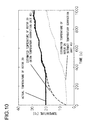
- Fig. 10 shows results of comparison between an actual temperature of the rotor 20 and the temperature estimated by the magnet temperature calculation unit 32.
- a solid line represents the actual temperature of the rotor 20;
- a broken line represents a case where the estimated temperature of the rotor 20 by the magnet temperature calculation unit 32 is corrected by the temperature correction unit 45;
- a dotted line represents a case where the estimated temperature of the rotor 20 by the magnet temperature calculation unit 32 is not corrected by the temperature correction unit 45 (corresponding to a case where the coil temperature sensor 16 and the internal air temperature sensor 17 have failed).
- estimate errors of the temperature of the rotor 20 are reduced as compared to the case where the correction by the temperature correction unit 45 is not performed.
- temperature information of each part of the motor can be calculated based on the temperature detected by the coil temperature sensor 16 and the drive status of the motor, that is, the external air temperature signal, the cooling water temperature signal, the torque signal, and the rotational frequency signal.
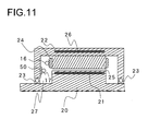
- Fig. 11 is a diagram illustrating a schematic configuration of a motor 2 according to a second embodiment of the present invention.
- part of the configuration of the aforementioned first embodiment (the configuration of the motor 2) is changed.
- the same reference numerals as those in Fig. 1 are assigned to the same elements as those shown in Fig. 1 and the following description will be mainly focused on the difference between the first and second embodiments.
- the internal air temperature sensor 17 is secured to the case 22 via an internal-air-temperature-detection-point heat insulating material 50 whose heat transfer coefficient is lower than that of the case 22. It is possible to prevent failures due to vibrations or the like and enhance reliability of the internal air temperature sensor 17 by directly securing the internal air temperature sensor 17 to the case 22 via the internal-air-temperature-detection-point heat insulating material 50.
- the internal air temperature sensor 17 is secured to the case 22 via the internal-air-temperature-detection-point heat insulating material 50 whose heat transfer coefficient is lower than that of the case 22, the heat transmitted and received between the case 22 and the internal air temperature sensor 17 can be reduced and the temperature of the internal air 27 can be detected with a high degree of accuracy. In this way, both measurement accuracy and reliability of the internal air temperature sensor 17 can be achieved.
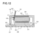
- Fig. 12 is a diagram illustrating a schematic configuration of a motor 2 according to a third embodiment of the present invention.
- part of the configuration of the aforementioned first embodiment (the configuration of the motor 2) is changed.
- the same reference numerals as those in Fig. 1 are assigned to the same elements as those shown in Fig. 1 and the following description will be mainly focused on the difference between the first and third embodiments.
- the internal air temperature sensor 17 is attached to the stator 25 via the internal-air-temperature-detection-point support member 18.
- a space is provided between the internal air temperature sensor 17 and the stator 25 without having them directly contact each other, so that the temperature of the internal air 27 can be measured with a high degree of accuracy without being influenced by the temperature of the stator 25 and the temperatures of the rotor 20 and the magnet 21 can be estimated more highly accurately.
- a coil temperature sensor signal line 51 which is a signal line of the coil temperature sensor 16 and an internal air temperature sensor signal line 52 which is a signal line of the internal air temperature sensor 17 can be integrated by attaching the internal air temperature sensor 17 to the stator 25, thereby making it possible to enhance assemblability of the motor 2.
- a ceramic structure is used as the internal-air-temperature-detection-point support member 18; however, instead of using this ceramic structure, the internal-air-temperature-detection-point support member 18 may be used as a signal line for transmitting measurement information of the internal air temperature sensor 17 and this signal line may be extended to attach the internal air temperature sensor 17 to the case 22 so that the internal air temperature sensor 17 will not directly contact the case 22.
- Fig. 13 is a diagram illustrating a schematic configuration of a motor drive device according to a fourth embodiment of the present invention.
- part of the configuration of the aforementioned first embodiment (the configuration of the control calculation unit 8) is changed.
- the same reference numerals as those in Fig. 1 are assigned to the same elements as those shown in Fig. 1 and the following description will be mainly focused on the difference between the first and fourth embodiments.
- the control calculation unit 8 is composed of: a first control calculation unit 61 that calculates the size of an electric current applied to the motor 2 and a frequency of the alternating current; and a second control calculation unit 62 that calculates a torque command of the motor 2.
- the first control calculation unit 61 and the second control calculation unit 62 have separate CPUs and memories, respectively, and signals can be sent and received between the first control calculation unit 61 and the second control calculation unit 62.
- the second control calculation unit 62 mainly performs calculations which do not depend on the motor 2.
- the second control calculation unit 62 is connected to the vehicle speed sensor 9, the accelerator sensor 10, the brake sensor 11, and so on.
- the second control calculation unit 62 calculates the torque command of the motor 2 and sends it to the first control calculation unit 61, and calculates the braking force command and sends it to the braking device 7.
- the first control calculation unit 61 mainly executes calculations specific to the motor 2.
- the first control calculation unit 61 is connected to the external air temperature sensor 12, the torque sensor 13, the rotational frequency sensor 14, the cooling water temperature sensor 15, the coil temperature sensor 16, the internal air temperature sensor 17, and so on.
- the first control calculation unit 61 calculates the size of the electric current applied to the motor 2 and the frequency of the alternating current based on the torque command sent from the second control calculation unit 62 and sends a command to the inverter power source 3, and also calculates the temperatures of the rotor 20 and the magnet 21 and sends them to the second control calculation unit 62.
- the first control calculation unit 61 has the functions of the magnet temperature calculation unit 32 in Fig. 6 and the second control calculation unit 62 has the respective functions of the torque request calculation unit 30, the braking force request calculation unit 31, the torque limit calculation unit 33, the rotational frequency limit calculation unit 34, the torque command calculation unit 35, and the braking force command calculation unit 36 in Fig. 6 .
- program maintenability can be enhanced by employing the configuration in which execution parts are provided separately for the calculations specific to the motor 2 and for the calculations which do not depend on the motor 2. For example, when specifications of the vehicle are changed and properties of the motor 2 change, it is only necessary to modify only the first control calculation unit 61.
Landscapes
- Engineering & Computer Science (AREA)
- Power Engineering (AREA)
- Transportation (AREA)
- Mechanical Engineering (AREA)
- Microelectronics & Electronic Packaging (AREA)
- Life Sciences & Earth Sciences (AREA)
- Sustainable Development (AREA)
- Sustainable Energy (AREA)
- Control Of Electric Motors In General (AREA)
- Electric Propulsion And Braking For Vehicles (AREA)
- Motor Or Generator Cooling System (AREA)
Applications Claiming Priority (2)
| Application Number | Priority Date | Filing Date | Title |
|---|---|---|---|
| JP2012259290A JP2014107956A (ja) | 2012-11-28 | 2012-11-28 | モータ、制御装置およびモータ駆動装置 |
| PCT/JP2013/078409 WO2014083963A1 (fr) | 2012-11-28 | 2013-10-21 | Moteur, dispositif de commande et dispositif d'entraînement de moteur |
Publications (2)
| Publication Number | Publication Date |
|---|---|
| EP2928050A1 true EP2928050A1 (fr) | 2015-10-07 |
| EP2928050A4 EP2928050A4 (fr) | 2016-06-08 |
Family
ID=50827609
Family Applications (1)
| Application Number | Title | Priority Date | Filing Date |
|---|---|---|---|
| EP13858744.9A Withdrawn EP2928050A4 (fr) | 2012-11-28 | 2013-10-21 | Moteur, dispositif de commande et dispositif d'entraînement de moteur |
Country Status (5)
| Country | Link |
|---|---|
| US (1) | US20150303860A1 (fr) |
| EP (1) | EP2928050A4 (fr) |
| JP (1) | JP2014107956A (fr) |
| CN (1) | CN104823370A (fr) |
| WO (1) | WO2014083963A1 (fr) |
Cited By (5)
| Publication number | Priority date | Publication date | Assignee | Title |
|---|---|---|---|---|
| EP3203616A1 (fr) * | 2016-02-02 | 2017-08-09 | Siemens Aktiengesellschaft | Procédé de refroidissement de générateur électrique |
| EP3361627A1 (fr) * | 2017-02-14 | 2018-08-15 | Valeo Equipements Electriques Moteur | Alterno-démarreur, véhicule automobile et procédé de commande associé |
| CN108885148A (zh) * | 2016-04-07 | 2018-11-23 | 罗伯特·博世有限公司 | 转矩感测装置和车辆 |
| EP3625528A4 (fr) * | 2017-05-18 | 2021-01-13 | General Electric Company | Système et procédé d'estimation de la température de moteur d'un système de pas d'une éolienne |
| US20210268876A1 (en) * | 2018-10-03 | 2021-09-02 | Carrier Corporation | Generator temperature control |
Families Citing this family (21)
| Publication number | Priority date | Publication date | Assignee | Title |
|---|---|---|---|---|
| WO2011130785A1 (fr) * | 2010-04-20 | 2011-10-27 | Corbett Research Pty Ltd | Procédé et appareil de commande de la température |
| JP2014045575A (ja) * | 2012-08-27 | 2014-03-13 | Toyota Motor Corp | 回転電機の駆動制御装置 |
| JP5695013B2 (ja) * | 2012-11-02 | 2015-04-01 | 本田技研工業株式会社 | 回転電機の磁石温度推定装置及び磁石温度推定方法 |
| JP2016082698A (ja) * | 2014-10-16 | 2016-05-16 | 三菱電機株式会社 | モータの温度推定装置及びモータの過熱保護方法 |
| US10308352B2 (en) * | 2014-12-12 | 2019-06-04 | Borealis Technical Limited | Monitoring system for aircraft drive wheel system |
| JP6480729B2 (ja) * | 2014-12-27 | 2019-03-13 | 日立オートモティブシステムズ株式会社 | ブレーキ装置 |
| DE112015006424B4 (de) * | 2015-04-09 | 2023-03-23 | Mitsubishi Electric Corporation | Steuervorrichtung für einen Stellmotor, Stellmotor, Ventilbetriebsvorrichtung und Steuerverfahren für einen Stellmotor |
| JP6614798B2 (ja) * | 2015-05-20 | 2019-12-04 | 本田技研工業株式会社 | 回転電機の温度制御装置 |
| CN106712650B (zh) * | 2015-11-13 | 2019-04-23 | 北汽福田汽车股份有限公司 | 电机扭矩的控制方法、控制系统及车辆 |
| CN105762990B (zh) * | 2016-04-18 | 2019-04-12 | 中国船舶重工集团公司第七一二研究所 | 一种高速电机 |
| DE102016117529A1 (de) * | 2016-06-02 | 2017-12-07 | Trafag Ag | Drehmomentsensoranordnung und Verfahren zur Drehmomentmessung sowie Drehmomentregelvorrichtung und Elektroantrieb |
| DE102016213639A1 (de) * | 2016-07-26 | 2018-02-01 | Voith Patent Gmbh | Antriebsvorrichtung und Verfahren zur Drehzahllimitierung |
| JP6500878B2 (ja) * | 2016-11-16 | 2019-04-17 | トヨタ自動車株式会社 | 回転電機の冷却構造 |
| JP6740114B2 (ja) * | 2016-12-22 | 2020-08-12 | 株式会社デンソー | モータシステム |
| JP6906423B2 (ja) * | 2017-10-26 | 2021-07-21 | 日立Astemo株式会社 | 制振装置 |
| JP7363528B2 (ja) * | 2020-01-28 | 2023-10-18 | マツダ株式会社 | モータの磁石温度推定装置、及びそれを備えるハイブリッド車 |
| CN113446156B (zh) * | 2020-03-27 | 2023-07-11 | 新疆金风科技股份有限公司 | 变桨系统的状态监测方法、装置、设备及介质 |
| IT202100028772A1 (it) * | 2021-11-12 | 2023-05-12 | Eldor Corp Spa | Method for reconfiguring an electric machine |
| JP7582259B2 (ja) | 2022-06-10 | 2024-11-13 | トヨタ自動車株式会社 | 電動機内部温度の推定装置、及び電動機の制御装置 |
| CN115714509B (zh) * | 2022-11-28 | 2026-01-02 | 浙江佳乐科仪股份有限公司 | 具有温控性能的电机 |
| WO2024176861A1 (fr) * | 2023-02-21 | 2024-08-29 | 日本精工株式会社 | Procédé d'estimation de température de dispositif de rotation, dispositif d'estimation de température et programme |
Family Cites Families (13)
| Publication number | Priority date | Publication date | Assignee | Title |
|---|---|---|---|---|
| JPS5419103A (en) * | 1977-07-13 | 1979-02-13 | Toshiba Corp | Humidity controller for rotary machine |
| JPH05284692A (ja) * | 1992-03-30 | 1993-10-29 | Toshiba Corp | 回転電機のコイル温度監視装置 |
| JP3627374B2 (ja) * | 1996-05-20 | 2005-03-09 | 株式会社富士通ゼネラル | 電動機の温度過昇保護装置 |
| JP2001099565A (ja) * | 1999-09-30 | 2001-04-13 | Toshiba Corp | 冷凍冷蔵庫 |
| DE19961528C1 (de) * | 1999-12-20 | 2001-06-13 | Siemens Ag | Verfahren zur Überwachung des radialen Spalts zwischen dem Rotor und dem Stator eines elektrischen Generators und Vorrichtung zur Durchführung des Verfahrens |
| JP2002142403A (ja) * | 2000-10-31 | 2002-05-17 | Yamamoto Denki Kk | 整流子モータ及びこれを用いた電動自転車用モータ駆動ユニット |
| JP2002142396A (ja) * | 2000-10-31 | 2002-05-17 | Yamamoto Denki Kk | モータの回転子及びこれを用いたモータ、並びに回転子の製造方法 |
| JP2002350019A (ja) * | 2002-04-10 | 2002-12-04 | Matsushita Refrig Co Ltd | 透明氷の製造方法 |
| JP2005045980A (ja) * | 2003-07-25 | 2005-02-17 | Nsk Ltd | 電動式パワーステアリング装置 |
| US6903525B2 (en) * | 2003-08-05 | 2005-06-07 | Kendro Laboratory Products, Lp | Motor temperature sensor system and method to determine motor performance |
| JP4910634B2 (ja) | 2006-10-27 | 2012-04-04 | 日産自動車株式会社 | モータの温度保護装置、およびモータ温度保護方法 |
| JP2010200515A (ja) * | 2009-02-26 | 2010-09-09 | Nissan Motor Co Ltd | 電動機の磁石温度推定装置 |
| JP5624667B2 (ja) * | 2011-02-21 | 2014-11-12 | 株式会社日立製作所 | モータ |
-
2012
- 2012-11-28 JP JP2012259290A patent/JP2014107956A/ja active Pending
-
2013
- 2013-10-21 EP EP13858744.9A patent/EP2928050A4/fr not_active Withdrawn
- 2013-10-21 US US14/646,972 patent/US20150303860A1/en not_active Abandoned
- 2013-10-21 WO PCT/JP2013/078409 patent/WO2014083963A1/fr not_active Ceased
- 2013-10-21 CN CN201380062225.3A patent/CN104823370A/zh active Pending
Cited By (12)
| Publication number | Priority date | Publication date | Assignee | Title |
|---|---|---|---|---|
| EP3203616A1 (fr) * | 2016-02-02 | 2017-08-09 | Siemens Aktiengesellschaft | Procédé de refroidissement de générateur électrique |
| WO2017133884A1 (fr) * | 2016-02-02 | 2017-08-10 | Siemens Aktiengesellschaft | Procédé de refroidissement de générateur électrique |
| US11005340B2 (en) | 2016-02-02 | 2021-05-11 | Siemens Gamesa Renewable Energy A/S | Electric generator cooling method |
| CN108885148A (zh) * | 2016-04-07 | 2018-11-23 | 罗伯特·博世有限公司 | 转矩感测装置和车辆 |
| CN108885148B (zh) * | 2016-04-07 | 2021-04-27 | 罗伯特·博世有限公司 | 转矩感测装置和车辆 |
| US11022508B2 (en) | 2016-04-07 | 2021-06-01 | Robert Bosch Gmbh | Torque detection unit and vehicle |
| EP3361627A1 (fr) * | 2017-02-14 | 2018-08-15 | Valeo Equipements Electriques Moteur | Alterno-démarreur, véhicule automobile et procédé de commande associé |
| FR3062974A1 (fr) * | 2017-02-14 | 2018-08-17 | Valeo Equipements Electriques Moteur | Alterno-demarreur, vehicule automobile et procede de commande associe |
| EP3625528A4 (fr) * | 2017-05-18 | 2021-01-13 | General Electric Company | Système et procédé d'estimation de la température de moteur d'un système de pas d'une éolienne |
| US11629701B2 (en) | 2017-05-18 | 2023-04-18 | General Electric Company | System and method for estimating motor temperature of a pitch system of a wind turbine |
| US20210268876A1 (en) * | 2018-10-03 | 2021-09-02 | Carrier Corporation | Generator temperature control |
| US12384226B2 (en) * | 2018-10-03 | 2025-08-12 | Carrier Corporation | Generator temperature control |
Also Published As
| Publication number | Publication date |
|---|---|
| JP2014107956A (ja) | 2014-06-09 |
| EP2928050A4 (fr) | 2016-06-08 |
| US20150303860A1 (en) | 2015-10-22 |
| CN104823370A (zh) | 2015-08-05 |
| WO2014083963A1 (fr) | 2014-06-05 |
Similar Documents
| Publication | Publication Date | Title |
|---|---|---|
| EP2928050A1 (fr) | Moteur, dispositif de commande et dispositif d'entraînement de moteur | |
| CN101387688B (zh) | 用于电动马达转矩监测的方法和设备 | |
| CN105599700B (zh) | 用于温度传感器故障检测的方法和系统 | |
| CN108025651B (zh) | 具有制动系统的车辆以及用于制动系统的方法和控制器 | |
| US8886375B2 (en) | Control apparatus for electric vehicle | |
| JP5924628B2 (ja) | 車両用制動力発生装置 | |
| CN104203634A (zh) | 旋转电机控制装置 | |
| KR101646467B1 (ko) | 친환경자동차의 모터 감자 진단 방법 | |
| CN103222184A (zh) | 用于使他励电机运行的方法和设备 | |
| CN115107732A (zh) | 用于在速度控制期间检测意外加速的车辆监测策略 | |
| WO2020099049A1 (fr) | Unité et système de surveillance d'état de freinage actif | |
| JP5760865B2 (ja) | 車両用モータ温度検出装置 | |
| KR20150122996A (ko) | 하이브리드 차량의 건식 클러치 열화 판단 방법 | |
| JP5322994B2 (ja) | ハイブリッド車両の発電制御装置 | |
| KR20220017052A (ko) | 하이브리드 차량의 속도 검출 장치 및 그 방법 | |
| US9783189B2 (en) | Control apparatus for vehicle and control method for vehicle | |
| US12374175B2 (en) | Detecting degradation within electric motors | |
| JP2015209055A (ja) | 冷却機構故障検知装置 | |
| CN104380593A (zh) | 车用交流发电机的控制装置 | |
| JP6095004B2 (ja) | 回転電機制御装置 | |
| JP6958458B2 (ja) | 電気自動車 | |
| US20240241530A1 (en) | Dynamic models for motor winding temperature | |
| JPH11341896A (ja) | モータの制御方法およびモータの制御装置 | |
| JP6066789B2 (ja) | 車両用制御装置 | |
| KR20230081797A (ko) | 인휠 모터 구동 차량의 구동계 고장 예측시스템 및 이를 이용한 인휠 모터 구동 차량의 구동계 고장 예측방법 |
Legal Events
| Date | Code | Title | Description |
|---|---|---|---|
| PUAI | Public reference made under article 153(3) epc to a published international application that has entered the european phase |
Free format text: ORIGINAL CODE: 0009012 |
|
| 17P | Request for examination filed |
Effective date: 20150629 |
|
| AK | Designated contracting states |
Kind code of ref document: A1 Designated state(s): AL AT BE BG CH CY CZ DE DK EE ES FI FR GB GR HR HU IE IS IT LI LT LU LV MC MK MT NL NO PL PT RO RS SE SI SK SM TR |
|
| AX | Request for extension of the european patent |
Extension state: BA ME |
|
| DAX | Request for extension of the european patent (deleted) | ||
| RA4 | Supplementary search report drawn up and despatched (corrected) |
Effective date: 20160510 |
|
| RIC1 | Information provided on ipc code assigned before grant |
Ipc: H02P 29/00 20160101ALI20160503BHEP Ipc: H02K 11/00 20160101AFI20160503BHEP |
|
| STAA | Information on the status of an ep patent application or granted ep patent |
Free format text: STATUS: EXAMINATION IS IN PROGRESS |
|
| 17Q | First examination report despatched |
Effective date: 20170616 |
|
| STAA | Information on the status of an ep patent application or granted ep patent |
Free format text: STATUS: THE APPLICATION HAS BEEN WITHDRAWN |
|
| 18W | Application withdrawn |
Effective date: 20170811 |