EP2928637B1 - Dispositif destiné au serrage et à l'alignement de pièces profilées creuses, à parois minces et sous forme de segments, et son utilisation - Google Patents
Dispositif destiné au serrage et à l'alignement de pièces profilées creuses, à parois minces et sous forme de segments, et son utilisation Download PDFInfo
- Publication number
- EP2928637B1 EP2928637B1 EP13830213.8A EP13830213A EP2928637B1 EP 2928637 B1 EP2928637 B1 EP 2928637B1 EP 13830213 A EP13830213 A EP 13830213A EP 2928637 B1 EP2928637 B1 EP 2928637B1
- Authority
- EP
- European Patent Office
- Prior art keywords
- clamping
- elements
- support structure
- support
- components
- Prior art date
- Legal status (The legal status is an assumption and is not a legal conclusion. Google has not performed a legal analysis and makes no representation as to the accuracy of the status listed.)
- Active
Links
Images



Classifications
-
- B—PERFORMING OPERATIONS; TRANSPORTING
- B23—MACHINE TOOLS; METAL-WORKING NOT OTHERWISE PROVIDED FOR
- B23K—SOLDERING OR UNSOLDERING; WELDING; CLADDING OR PLATING BY SOLDERING OR WELDING; CUTTING BY APPLYING HEAT LOCALLY, e.g. FLAME CUTTING; WORKING BY LASER BEAM
- B23K37/00—Auxiliary devices or processes, not specially adapted for a procedure covered by only one of the other main groups of this subclass
- B23K37/04—Auxiliary devices or processes, not specially adapted for a procedure covered by only one of the other main groups of this subclass for holding or positioning work
- B23K37/0417—Auxiliary devices or processes, not specially adapted for a procedure covered by only one of the other main groups of this subclass for holding or positioning work for spherical work
-
- B—PERFORMING OPERATIONS; TRANSPORTING
- B23—MACHINE TOOLS; METAL-WORKING NOT OTHERWISE PROVIDED FOR
- B23K—SOLDERING OR UNSOLDERING; WELDING; CLADDING OR PLATING BY SOLDERING OR WELDING; CUTTING BY APPLYING HEAT LOCALLY, e.g. FLAME CUTTING; WORKING BY LASER BEAM
- B23K37/00—Auxiliary devices or processes, not specially adapted for a procedure covered by only one of the other main groups of this subclass
- B23K37/04—Auxiliary devices or processes, not specially adapted for a procedure covered by only one of the other main groups of this subclass for holding or positioning work
- B23K37/053—Auxiliary devices or processes, not specially adapted for a procedure covered by only one of the other main groups of this subclass for holding or positioning work aligning cylindrical work; Clamping devices therefor
- B23K37/0531—Internal pipe alignment clamps
-
- B—PERFORMING OPERATIONS; TRANSPORTING
- B23—MACHINE TOOLS; METAL-WORKING NOT OTHERWISE PROVIDED FOR
- B23Q—DETAILS, COMPONENTS, OR ACCESSORIES FOR MACHINE TOOLS, e.g. ARRANGEMENTS FOR COPYING OR CONTROLLING; MACHINE TOOLS IN GENERAL CHARACTERISED BY THE CONSTRUCTION OF PARTICULAR DETAILS OR COMPONENTS; COMBINATIONS OR ASSOCIATIONS OF METAL-WORKING MACHINES, NOT DIRECTED TO A PARTICULAR RESULT
- B23Q3/00—Devices holding, supporting, or positioning work or tools, of a kind normally removable from the machine
- B23Q3/02—Devices holding, supporting, or positioning work or tools, of a kind normally removable from the machine for mounting on a work-table, tool-slide, or analogous part
- B23Q3/06—Work-clamping means
- B23Q3/062—Work-clamping means adapted for holding workpieces having a special form or being made from a special material
-
- B—PERFORMING OPERATIONS; TRANSPORTING
- B23—MACHINE TOOLS; METAL-WORKING NOT OTHERWISE PROVIDED FOR
- B23Q—DETAILS, COMPONENTS, OR ACCESSORIES FOR MACHINE TOOLS, e.g. ARRANGEMENTS FOR COPYING OR CONTROLLING; MACHINE TOOLS IN GENERAL CHARACTERISED BY THE CONSTRUCTION OF PARTICULAR DETAILS OR COMPONENTS; COMBINATIONS OR ASSOCIATIONS OF METAL-WORKING MACHINES, NOT DIRECTED TO A PARTICULAR RESULT
- B23Q3/00—Devices holding, supporting, or positioning work or tools, of a kind normally removable from the machine
- B23Q3/02—Devices holding, supporting, or positioning work or tools, of a kind normally removable from the machine for mounting on a work-table, tool-slide, or analogous part
- B23Q3/06—Work-clamping means
- B23Q3/062—Work-clamping means adapted for holding workpieces having a special form or being made from a special material
- B23Q3/065—Work-clamping means adapted for holding workpieces having a special form or being made from a special material for holding workpieces being specially deformable, e.g. made from thin-walled or elastic material
-
- B—PERFORMING OPERATIONS; TRANSPORTING
- B23—MACHINE TOOLS; METAL-WORKING NOT OTHERWISE PROVIDED FOR
- B23K—SOLDERING OR UNSOLDERING; WELDING; CLADDING OR PLATING BY SOLDERING OR WELDING; CUTTING BY APPLYING HEAT LOCALLY, e.g. FLAME CUTTING; WORKING BY LASER BEAM
- B23K2101/00—Articles made by soldering, welding or cutting
- B23K2101/04—Tubular or hollow articles
- B23K2101/12—Vessels
Definitions
- the present invention relates to a device for clamping and aligning segmental, thin-walled and hollow-profiled components and their use.
- Such devices for clamping hollow profiled workpieces with circular cross sections, for example cylindrical shots, spherical shells, domes, etc., which are to be milled, welded or otherwise processed from the outside, are well known.
- Such devices essentially consist of radially arranged segments, which can be extended for example by means of conical spikes, hydraulic pistons or the like against the inner walls of the workpieces.
- Such devices are, inter alia, for the production of segment-like, thin-walled and hollow-profiled components, such as pressure vessels for storing cryogenic liquids, in particular liquid hydrogen (LH2), provided.
- LH2 liquid hydrogen
- Such pressure vessels or tanks can be used in all automotive sectors, such as aerospace, ship and boat building and in particular in the automotive industry.
- a major problem in the production of such pressure vessels results from their arbitrarily varying shapes, their extremely large dimensions with a diameter of up to about 6, 0 m or more and a length of up to 25 m and in relation to extremely low wall thickness with a wall thickness in the range of about 3.3 mm to a maximum of 7 mm.
- a device is in the DE 100 55 257 C2 described. This device has proven extremely effective in practice, although their production and operation has been found to be relatively expensive, since each Clamping element is assigned a separate drive means, such as in the form of a stepping motor or a piston device, as a clamping actuating element.
- this device is due to the centric arrangement of the clamping elements in a plane perpendicular to the longitudinal axis evenly distributed and because of the formation of the clamping elements to each other for the production of, for example, pressure vessels or tanks that are partially closed and thus restrictedly accessible from the outside, not suitable.
- a clamping device with a plurality of arranged in at least one clamping plane, independently movable or actuated clamping elements for low-deformation clamping extremely thin-walled workpieces, in particular of rings and pipes described.
- a central drive in the form of a pressure-medium-actuated piston is provided. By an axial movement of the piston, the clamping elements are moved together radially outward.
- each clamping element is additionally provided with an individually pressure medium-actuated drive and / a separately assigned sensor or probe rod, the / on actuation of the clamping elements an approximation or nearly powerless system Determines clamping elements on the workpieces and causes either a shutdown of the individual drive or a clamping of the clamping element.
- a device for aligning and clamping of two pipes to be welded together emerges.
- a plurality of clamping elements arranged in a clamping plane is radially movable from the inside to the outside or from the outside inwards away from the inner wall of the tubes.
- the clamping elements are each received via link rods in slotted guides a disc which is mounted on a central axis and limited by pneumatically or hydraulically acting actuators in and counterclockwise rotatably limited. Due to the rotational movement of the disc, the clamping elements are radially displaceable.
- the shows US 5 444 902 A a device for straightening and holding a cylinder.
- an upper and lower frame for receiving the cylinder in the region of the upper and lower ends are provided.
- a plurality of radially arranged screw spindles is provided, wherein in each case a clamping element is arranged on a pair of screw spindles.
- the screw spindles and thus the clamping elements are radially outward to and inward away from the cylinder to be rotated and kept to be moved.
- a clamping device with a clamping element which is to be radially displaceable in a guide via an inflatable tube by means of compressed air, is used exclusively for fixing the device in the longitudinal direction of the cylindrical tube segments and is not comparable with a clamping device in terms of function and design.
- the GB 835 030 A shows a welding device for clamping and alignment of segmented, thin-walled and hollow profiled components.
- This welding device comprises a supported on or on a base support structure 14 and a received and held by the support structure means for clamping two segmented, thin-walled and hollow profiled components, wherein the clamping device is designed such that the two components in the region of their common parting plane of the clamping device perpendicular to the longitudinal axis of the support structure and radially from the inside to the outside can be acted upon, and at least two arranged in a common plane and radially from inside to outside, and vice versa, slidable clamping elements with the two components acted upon clamping surfaces, wherein the clamping device the comprises at least two clamping elements.
- the US 5 435 479 A finally, discloses a cylindrical rounding and clamping fixture for welded joints that is assembled solely on mechanical and electrical components. Even the drive device for rotating an actuating ring is based on an electric motor, which is preferably designed as a DC motor.
- the present invention is therefore an object of the invention to provide a device for clamping and alignment of segmented, thin-walled and hollow profiled components available, which structurally particularly simple design, a light as fast assembly and disassembly on the one hand and at the same time generating high pressure forces allows and at the same time extremely versatile, and to provide their use.
- the device according to the invention for clamping and aligning segmental, thin-walled and hollow profiled components comprising a supported on or on a base support structure or the like frame and a recorded and held by the support structure clamping device for clamping two segmental, thin-walled and hollow profiled Components, wherein the clamping device is designed such that the two components in the region of their common parting plane of the clamping device perpendicular to the longitudinal axis of the support structure and radially from the inside are acted upon, at least two arranged in a common plane and radially from the inside to the outside , And vice versa, displaceable clamping elements with the two components acting on clamping surfaces and at least one at least two clamping elements together acted upon Spannbetuschistorselement, the tubular or e in hose, in particular with one or more chambers, is formed and the at least two clamping elements acted by volume change perpendicular to the longitudinal axis of the support structure radially from inside to outside,
- the device according to the invention is due to a by the at least two clamping elements jointly acting Spannbetuschistselement to be achieved room layout, space utilization and thus space saving in a particularly versatile manner for the production of pressure vessels or tanks of components of arbitrary design and form. Due to the special design of the clamping actuating element, it is possible to clamp two components of any shape in the region of their common parting plane perpendicular to the longitudinal axis of the support structure and radially from the inside to the outside and to align each other.
- two components of, for example, substantially cylindrical shape, which are freely accessible from the outside or at least partially freely accessible, and / or components which are accessible from the outside limited only by recesses or openings in at least one of the two components, from the clamping device the device according to the invention are acted upon radially from the inside out.
- components of different design and shape are about to pressure vessels or tanks produced, which could be accomplished in the prior art, in principle, only from several different devices, in each case specifically tailored to the design and shape of the components on the one hand and the resulting accessibility in their home on the other hand dependent. Even complex multi-part pressure vessels or tanks can thus be produced with the device according to the invention.
- the device according to the invention is thus particularly versatile.
- pressure vessel with extremely large dimensions such as with a diameter of up to about 6, 0 m or more and a length of up to 25 m, with an accuracy of up to 0.1 mm with a wall thickness range of about 2 mm to about 20 mm.
- the clamping device is extremely easy to disassemble and thus even in the interior of a container or a or more component / s, which are accessible from the outside limited only by recesses or openings in at least one of the two components, can be mounted or subsequently dismantled again.
- Pressure vessels with a diameter of about 5.0 m and a circumference of about 18.0 m, for example, only recesses or openings less than or equal to 1 m, through which the clamping device are passed and moved out after processing of the components or the container have to.
- radial forces and / or torques of up to 10 t and more which occur during machining of the component (s), for example in friction stir (FSW) welding, can occur uniformly over the entire circumference thereof / or distribute consistently.
- a stepless mobility is possible. It can be exercised with the clamping device in a small space and / or with even minor displacement extremely high forces on the components.
- Radial forces and / or torques of sometimes up to 100 t and more, which occur during machining of the component (s), for example during tungsten inert gas (TIG) welding can also be achieved with the clamping device according to the invention, generate to allow a homogeneous expansion of the / s components / s.
- the clamping device is particularly versatile.
- the clamping device can be used together with a variety of facilities for processing the / s components / s.
- the tensioning device can be used in a particularly advantageous manner when the component (s) are to be welded or welded together, for example, completely independently of the respective welding method.
- the clamping device can therefore be used equally with a friction stir (FSW) welding device or a tungsten inert gas (TIG) welding device or any other welding device.
- the tensioning device comprises at least two segment-like support ring elements which are arranged between the support structure or the support element of the support structure and the at least one tensioning actuating element.
- the number of support ring elements is basically arbitrary. In practice, the number of support ring elements - just like that of at least two clamping elements - but according to the weight of a single support ring element to be handled by the staff, that is to lift and wear, according to the diameter of the components themselves, the size and accessibility of the recesses and openings, etc. determine.
- the multi-part support ring disassembly of the clamping device after processing and / or welding of the two components together to a container and subsequent removal of the at least two segment-like support ring elements ensured by much smaller recesses or openings in the container.
- the support ring enables considerable pressure loads, which occur, for example, during friction stir (FSW) welding, readily withstand and / or considerable shrinkage stresses, for example, the tungsten inert gas (TIG) welding counteract or apply large pressure and expansion forces to expand the / s homogenously / s and whose / their dimensions before and after the Keep welding constant. And this distributed over the entire circumference of the support ring evenly and / or consistently, without stress of support structure or support member of the support structure.
- FSW friction stir
- TOG tungsten inert gas
- the clamping device comprises a plurality of extendable and retractable support members which are arranged between the support structure or the support member of the support structure and the at least one clamping actuator.
- the clamping device comprises a plurality of extendable and retractable support members which are arranged between the support structure or the support member of the support structure and the at least one clamping actuator.
- the inventive design to be able to fold out the support elements is an introduction of the tensioning device according to the invention in two components of partially or completely closed form or even in a container, such as recesses or openings, such as poles or the like, and a positioning thereof inside the components or the container as well as a subsequent movement out of the two components or the container after the processing has been made possible. Even complex multi-part pressure vessels or tanks can therefore be produced with the device according to the invention.
- the at least one clamping actuator of the clamping device comprises a longitudinal axis of the support structure facing the pressure surface facing away from the longitudinal axis of the support structure, correspondingly formed pressure surface of the support structure or the support member of the support structure is engaged via the the at least one clamping actuating element on the support structure or the support element of the support structure is radially inwardly supportable.
- the at least one clamping actuating element of the tensioning device advantageously comprises a pressure surface facing away from the longitudinal axis of the support structure, which engages with correspondingly formed pressure surfaces of the at least two tensioning elements facing the longitudinal axis of the support structure such that the at least two tensioning elements engage by volume change of the at least one clamping actuating element substantially perpendicular or substantially perpendicular to the longitudinal axis of the support structure radially from the inside to the outside, and vice versa, are displaceable.
- the clamping device according to claim 4 comprises a pneumatic or hydraulic drive means for changing the volume of the at least one clamping actuator perpendicular or substantially perpendicular to the longitudinal axis of the support structure and thus for displacement of the at least two clamping elements.
- the at least one clamping actuating element of the clamping device according to claim 5 on the support structure or a support element of the support structure can be supported radially inwardly.
- the at least two segment-like support ring elements according to claim 6 form a multi-part support ring with a circumferential surface facing away from the longitudinal axis of the support structure can be mounted.
- the at least one clamping actuating element of the clamping device prefferably be designed to be radially inwardly supportable via the at least two segment-like support ring elements that can be mounted on ends of the extendable and retractable support elements.
- the clamping device according to claim 7 comprises a / a / n guide bush, ring or the like element, the / of the support structure or the support member of the support structure is axially displaceably received and on / the foldable and foldable Supporting elements are articulated.
- clamping device according to claim 8 with a drive device for the axial displacement of / the guide bush, ring or the like element.
- the drive device of the clamping device preferably comprises at least one manually, electromotively, mechanically, pneumatically or hydraulically driven and synchronized linear axis or piston for displacement of the / guide bush, ring or the like element.
- the invention provides to form the telescoping and retractable support elements.
- the clamping device according to claim 11 comprises guide elements, in particular bolts, via which the at least two clamping elements are received by the at least two segment-like support ring elements and guided radially displaceably.
- the guide elements of a clamping element according to the invention in each case to each other are substantially parallel arranged extending.
- the guide elements take the clamping elements according to claim 12 preferably on sockets, which are at least partially or completely made of elastic material, in particular made of rubber, to counteract a sluggishness or even jamming of the at least two clamping elements in their radial displacement.
- the clamping device comprises stop elements, in particular bolts.
- the stop elements are arranged between the at least two clamping elements and the at least two segment-like support ring elements and provided to limit the displaceability of the at least two clamping elements radially outwards.
- the stop elements according to claim 14 are pivotally received by the clamping elements.
- the stop elements are mounted in the clamping elements via (ball or cardan) joints.
- the locking elements are each associated with a stop element for locking and unlocking of the respective stop element and for temporarily fixing the at least two clamping elements in the maximum clamping state.
- the guide elements and / or stop elements and / or locking elements are alternatively or cumulatively thereto, in particular, provided with rotary, screw or the like operation buttons or handles.
- the at least two clamping elements of the clamping device are each formed as a clamping jaw.
- the number of clamping elements or clamping jaws to be provided depends on the individual technical requirements of the two components, their dimensions and / or material, the respective machining methods and processes, etc.
- the device according to the invention can be equipped with only two or 16, Be equipped 32 and more clamping elements or clamping jaws.
- the clamping device according to claim 17 is associated with at least one device for processing at least part of the two segment-like, thin-walled and hollow-profiled components.
- the welder may be based on Tungsten Inert Gas (TIG), Metal Inert Gas (MIG), Stirrer (FSW), Electron Beam (EB), Laser, Plasma, or any other suitable welding technique.
- Very preferably for the device according to the invention is a welding device based on friction stir (FSW) welding and / or tungsten inert gas (TIG) welding.
- the features of claim 19 provide an increase in accuracy in clamping and aligning the two components to each other and thus an improvement in the manufacturing accuracy overall. Accordingly, according to the invention is still provided that the clamping device on the support structure relative to the at least one device for machining the two segmental, thin-walled and hollow profiled components is relatively rotatable, in particular about the longitudinal axis of the support structure, and / or pivotable, in particular about a horizontal axis of rotation, is arranged.
- the relative pivotability makes it possible to produce each weld in the respectively optimal position by the liquid welding melt in the optimal / r position, namely in so-called / rannen for gravity, aligned and generated.
- the device according to the invention is preferably provided for clamping, in particular in the circumferential direction stress-free clamping, for mounting segmentally formed, thin-walled and hollow cylindrical components and containers, domes and booster housings of missiles or similar hollow cylindrical devices of large dimensions.
- the device according to the invention can be used for machining, in particular welding, soldering or gluing or cutting or grinding, milling, turning or similar surface treatment, of segment-like, thin-walled and hollow cylindrical components and containers, domes and booster housings or similar hollow cylindrical devices serve large dimensions.
- the apparatus according to the invention for producing rotationally symmetrical and / or non-rotationally symmetrical bowl-shaped, in particular hemispherical, spherical cap-shaped, dome-shaped, ellipsoidal kallotenförmig, conical, elliptical, in Cassini form, semi-torus -shaped or to be used with such other cross-sectional shapes designed components.
- the invention is very particularly suitable Device thereby for producing domes for rocket fuel tanks, satellite tanks, paraboloid antennas, paraboloid reflector shells, paraboloid solar collectors, headlight housings, container bottoms, tower domes, pressure domes or the like.
- the device 10 is intended for clamping and alignment of segmented, thin-walled and hollow cylindrical components and containers, domes and booster housings of rockets or similar hollow cylindrical devices of large dimensions.
- the device 10 is characterized in particular by a tension-free clamping in the circumferential direction, since the tension at or about the circumference in the region of the common parting plane is the same for the components is.
- the device 10 according to the invention is particularly suitable for machining, in particular for welding, soldering or gluing or cutting or grinding, milling, turning or similar surface treatment of segmental, thin-walled and hollow cylindrical components and containers, domes and booster housings or similar hollow cylindrical devices large Dimensions.
- the device 10 according to the invention is preferably used for producing rotationally symmetrical and / or non-rotationally symmetrical bowl-shaped, in particular hemispherical, spherical cap-shaped, dome-shaped, ellipsoidal kallotenförmig, conical, elliptical, Cassini-shaped, semi-toroidal or with the other other cross-sectional shapes configured components ,
- the apparatus 10 of the invention serves to manufacture components 12 such as rocket fuel tank domes, satellite tanks, paraboloid antennas, paraboloid reflector cups, paraboloid solar collectors, headlamp housings, container bottoms, tower domes, pressure domes, or the like.
- components 12 such as rocket fuel tank domes, satellite tanks, paraboloid antennas, paraboloid reflector cups, paraboloid solar collectors, headlamp housings, container bottoms, tower domes, pressure domes, or the like.
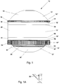
- Such a finished container 12 is in the Fig. 1 exemplified as a fuel tank of the Ariane 5 upper stage.
- the fuel tank 12 is composed of a plurality of segmented, thin-walled and hollow-profiled components 12 ', 12'', which differ considerably in shape and dimension from each other.
- the components 12 ', 12'' are adjacent to each other.
- the Fig. 1 is the fuel tank from an upper bulkhead 14, an upper skirt 16, an upper Y-ring 18, a hollow cylinder 20, a lower Y-ring 22, an elongated lower skirt 24, an inner dome (not to be seen) including an X-ring 26 and a LOX Dome or Lower Bulkhead 28 formed.
- the individual adjacent components 12 ', 12'' are each to each other weld.
- the corresponding welds S1, S2, S3, S4, S5, S6, S7 form connection points between in each case two adjacent components 12 ', 12 ".
- welds S3 or S5 according to the Fig. 1 and 1A to weld the Inner Dome 26 with the LOX Dome 28 or Upper Tank Compartment Upper Bulkhead 14 / Upper Skirt 16 with the Lower Tank Compartment and the hollow cylinder 20 together.
- the interior is in the case of welds S3 or S5 due to the / partially closed container 12 or components 12 ', 12''after processing or welding only accessible via small recesses or openings over which the device 10 according to the invention are moved out got to.
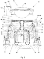
- Fig. 2 to 7B is an embodiment of the device 10 according to the invention for clamping and aligning the segment-like, thin-walled and hollow profiled components 12 ', 12''shown.
- the device 10 comprises a support structure 30 or the like frame or quasi machine table.
- the support structure 30 is supported on or on a base 32.
- the base 32 is a foundation, a (foundation) floor of a building or other basic console.
- the device 10 comprises a device 34 for clamping the container 12 and / or the two segment-like, thin-walled and hollow-profiled components 12 ', 12''.
- the tensioning device 34 is of the support structure 30, as shown in Fig. 2 can be seen, recorded and held.
- the support structure 30 includes, like the Fig. 2 shows, two support members 36, 36 '.
- the two support members 36, 36 ' are supported on or on the base 32 or the like foundation and are on or at the base 32 opposite each other, for example by means of screws, etc. (not shown), attachable in a conventional manner.
- the tensioning device 34 is held centrally by the support structure 30 between its two support elements 36, 36 'and, preferably rotatable or pivotable, for example, via a substantially horizontally extending axis of rotation 38 held.
- the clamping device 34 has, like the Fig. 2 can be removed, a table 40 or base on which the two components 12 ', 12''optionally with the interposition of an adapter element to position their height to be positioned, and a plurality of centering elements and clamping elements (not shown) on. By means of the centering elements and the clamping elements, the two components 12 ', 12 "positioned on the table or base are then aligned and releasably fixed or held.
- the clamping device 34 is formed such that the two components 12 ', 12' 'in the region of their common parting plane 42 of the clamping device 34 perpendicular or substantially perpendicular to the longitudinal axis 44 of the support structure 30, which is also the longitudinal axis of the device 10 , and can be acted upon radially from the inside to the outside.
- the clamping device 34 has at least two clamping elements 46 with clamping surfaces 48, which act on the two components 12 ', 12' 'on.
- the at least two clamping elements 46 are arranged in a common plane and radially from inside to outside, and vice versa, displaceable.
- the clamping device 34 are associated with the at least two clamping elements 46.
- the at least two clamping elements 46 of the clamping device 34 are preferably designed as individual clamping jaws.
- the number of clamping elements 46 or clamping jaws depends on the individual technical requirements of the two Components 12 ', 12'', their dimensions and / or material, the respective processing methods and processes, etc.
- the device 10 according to the invention can be equipped, for example, with only two clamping elements 46 or clamping jaws.
- a total of 16 clamping elements 46 and clamping jaws are provided.
- the number of clamping elements 46 may be as small as or larger.
- 32 clamping elements 46 (not shown) are provided.
- the tensioning device 34 additionally comprises at least one tensioning actuating element 50, which jointly acts on the at least two tensioning elements 46 or acts on the tensioning elements 46 simultaneously and to the same extent, i. the clamping elements 46 are all displaced radially outwardly in the direction of the two components 12 ', 12' 'or pressed or all radially inward in the direction of the longitudinal axis 40 of the support structure 30 and the device 10 and thus of the components 12', 12 ' 'retreats'.
- the at least one clamping actuating element 50 of the clamping device 34 is ring-shaped or annular.
- the at least one clamping actuating element 50 is configured in the form of a hose or a hose.
- the at least one clamping actuating element 50 can consist of one or more chambers which communicate with one another.
- the at least one clamping actuating element 50 is configured in such a way that the clamping elements 46 are acted on radially from inside to outside by volume change perpendicular to the longitudinal axis 40 of the supporting structure 30.
- a total of two clamping actuation elements 50 are provided. How in particular the Fig. 5A to 6B can be seen, the two clamping actuation elements 50 are arranged one above the other.
- the tensioning device 34 comprises a pneumatic or hydraulic drive device (not shown) for changing the volume in the at least one tensioning confirmation element 50 and consequently for changing the volume of the least two, here 16, tensioning elements 46 perpendicular or substantially perpendicular to the longitudinal axis 40 of the support structure 30
- Drive means conveys a pressure medium pneumatically or hydraulically in the two formed as a hose clamping actuation elements 50 which expand or contract accordingly.
- the two clamping actuating elements 50 of the clamping device 34 can be supported on the support structure 30 radially inwardly.
- a support member 52 is provided.
- the support element 52 is elongated and tubular and arranged centrally on the longitudinal axis 40 of the support structure 30.
- the support of the two clamping confirmation elements 50 takes place radially inwards via the support element 52 of the support structure 30.
- the support member 52 is preferably attached to the support structure 30, i. fixedly connected to the support structure 30. Alternatively or cumulatively, however, it may be equally possible and equally advantageous, without being shown in detail, to dispose the support element 50 displaceably on or parallel to the longitudinal axis 40 of the support structure 30 by means of a separate drive device (also not shown).
- the clamping device 34 comprises a plurality of extendable and retractable support members 54 or support arms, which are arranged between the support structure 30 and the support member 52 of the support structure 30 and the two clamping actuation elements 50.
- the support members 54 are formed and folded out to the support member 52 together with the at least one clamping actuator 50 in two components 12 ', 12''of partially or completely closed Form or even in a container 12 via recesses or openings, such as pole openings, bring in and be able to lead out again after processing through the same recesses or openings.
- the clamping device 34 For folding and unfolding of the support elements 54, the clamping device 34 has a guide bush 56, a guide ring or the like guide element.
- the guide bushing 56 is received axially displaceably by the support structure 30 or the support element 52 of the support structure 30.
- the extendable and retractable support members 54 are hinged to the guide bushing 56.
- the support arms 54 are unfolded at the axial displacement of the guide bush 56 upwards and folded down.
- extendable and retractable support members 54 are telescopically formed and thus changeable in their length.
- the clamping device 34 comprises at least two segment-like support ring members 62.
- the support ring members 62 are disposed between the support structure 30 or the support member 52 and the two clamping actuators 50.
- each support element 54 is assigned a segment-like support ring element 62.
- 16 support ring members 62 are provided.
- the segment-like support ring elements 62 are attached to the ends 64 of the respectively associated support elements 54 or at least mountable.
- the segment-like support ring members 62 are mountable to a multi-part support ring.
- the support members 54 are to be moved with the ends 64 in a position in which the segment-like support ring members 62 come into mutual contact with their respective adjacent support ring members 62 and then supported each other. Due to the pressure conditions, it has basically proven to be sufficient in practice to fix the respective left and right side adjacent support ring elements 62 without separate connecting elements, such as screws or the like, to each other.
- the respective adjacent support ring elements 62 are based on their associated sides or flanks from each other. Nevertheless, it is readily possible to connect the support ring members 62 with the respective left and right side adjacent support ring members 62 in addition screws or the like fasteners, as far as desired or constructive commanded.
- the individual segment-like support ring elements 62 can thus be assembled into a compact support ring in the form of a ring or annulus and put together or contract, whose peripheral surface of the longitudinal axis 40 of the support structure 30 faces away and forms a pressure surface 66 for the clamping actuator 50.
- the pressure surface 66 is thus annular or annular.
- the male and to be transferred loads can be distributed uniformly and / or consistently over the entire circumference of the support ring in this way, without claiming the support structure, the support member of the support structure or the support members.
- the two clamping actuation elements 50 of the tensioning device 34 comprise a pressure surface 68, which faces the longitudinal axis 40 of the support structure 30.
- the pressure surface 68 is in mutual contact and engagement with the pressure surface 66, which faces away from the longitudinal axis 40 of the support structure 30 and is designed accordingly.
- the two clamping actuation elements 50 of the tensioning device 34 are thus supported directly on the segment-like support ring members 62 which are mounted on the ends 64 of the retractable and retractable support members 54, and thus indirectly on the support structure 30 or the support member 50 of the support structure 30 radially inwardly ,
- the two clamping actuation elements 50 of the clamping device 34 further comprise a pressure surface 70, which faces away from the longitudinal axis 40 of the support structure 30.
- the clamping elements 46 also each have a pressure surface 72, which faces the longitudinal axis 40 of the support structure 30.
- the pressure surfaces 70, 72 are in mutual contact and engagement such that the tension members 46 are radially inwardly outwardly displaced by volume change of the tensioner (s) 50, substantially perpendicular or substantially perpendicular to the longitudinal axis 40 of the support structure 30, and vice versa. are displaceable.
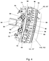
- the two clamping actuators 50 are insofar as from the Fig. 3 to 6B can be seen, extending circumferentially between the ends 64 of the support members 54 and the support ring members 62 and radially supported on the pressure surface 66 formed by the segment-like support ring members 62 to a ring or annulus radially inwardly. Via the pressure surface / s 72 of the clamping elements 46, their radial displacement takes place by volume change of the clamping actuating element 50 from the inside to the outside to the two components 12 ', 12''.
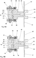
- the clamping device 34 For receiving, guiding and radial displacement of the clamping elements 46, the clamping device 34, as the Figs. 5A and 5B show guide elements 74, in particular in the form of bolts.
- guide elements 74 are received at the ends 64 of the support elements 54 and by the segment-like support ring elements 62.
- the guide elements 74 are inserted into the segment-like support ring elements 62 and connected captively to the support ring elements 62 via latching means 76 or the like.
- the guide elements 74 are held in the segment-like support ring elements 62, preferably without play, longitudinally displaceable.
- the guide elements 74 are additionally provided in each case with an actuating button 78 or the like handle.
- the guide elements 74 of an associated clamping element 46 each extend substantially parallel to one another.
- the clamping elements 46 are received by the segment-like support ring elements 62 and guided radially displaceable.
- bushes 80 are provided between the guide elements 74 and the clamping elements 46, which consist at least partially or completely of elastic material, in particular of rubber. This is a binding or even jamming of the clamping elements 46 counteracted in their radial displacement.
- the bushings 80 are additionally underlaid and reinforced with bushings 82 of metal or plastic, which are directly associated with the guide elements 74.
- the ease of movement in the radial displacement of the clamping elements 46 is favored according to the invention in a very advantageous manner.
- the clamping device 34 further comprises stop or limiting elements 84, in particular bolts.
- stop or limiting elements 84 in particular bolts.
- four stop or limiting elements 84 namely two lower and two upper stop or limiting elements 84, provided, even if the number of stop or limiting elements 84 can be changed arbitrarily.
- the stop elements 84 serve to limit the displaceability of the at least two clamping elements 46 radially outward.
- the stop elements 84 are arranged between the clamping elements 46 and the segment-like support ring elements 62.
- the stop or limiting elements 84 are inserted into the segment-like support ring elements 62 and connected captively to the support ring elements 62 by latching means 85 or the like.
- the guide elements 74 are held in the segment-like support ring elements 62 - preferably without play - longitudinally displaceable.
- stop elements 84 are additionally provided with in each case with an actuating button 86 or the like handle.
- the stop elements 84 are received by or in the clamping elements 46 articulated.
- the stop elements 84 are received by the clamping elements 46 via (ball or cardan) joints 88.
- the stop elements 84 are releasably fixed in the clamping elements 46 by fastening means 89, such as a snap ring or the like, in the clamping elements 46.
- the clamping device 34 further comprises locking elements 90.
- the locking elements 90 are each associated with a stop element 84 to lock and unlock the respective stop element 84 and thus temporarily fix the clamping elements 46 in the clamping state.
- the locking elements 90 are formed like a slide and each cooperate with two lateral grooves 96 in the stop member 84, in which the corresponding locking element 90 engages transversely to the longitudinal axis of the stop member 84 and the stop member 84 thus locks in the longitudinal direction.
- Fig. 7A is the locking element 90 in unlocked State shown in which the stop element 84 is freely movable.
- Fig. 7B the locking element 90 is shown in the locked state in which the locking element 90 engages in the grooves of the stop element 84.
- the locking element 90 itself is provided with latching means 94, comprising latching recesses in the locking element 90 and latching projections in the clamping elements 46 or support ring elements 62, which correspond to the Figs. 7A and 7B can be brought into two locking positions.
- clamping actuators 50 are formed tubular, can be achieved in this way that the clamping elements 46 during the entire processing of the container 12 and the components 12 ', 12' 'in the (maximum) clamping state is maintained. Even in the event of a leakage of one clamping actuator 50, which would necessarily be connected to a radial displacement of the clamping element (s) 46 in the defective area of the clamping actuator 50, the clamping element (s) will remain in the (maximum) clamping state. A faulty processing or even damage to the container 12 or the components 12 ', 12' 'during milling or welding are safely excluded.
- the locking elements 90 are additionally equipped with a rotary, screw or the like actuating button 96 or handle
- the processing device 98 can in this context as welding, soldering or Adhesive device or cutting device or grinding, milling, turning or the like surface and spanbeusedde and quality and material testing device to be formed.
- two processing devices 98 are provided, namely firstly a milling device 100 and secondly a welding device 102, preferably for friction stir (FSW) welding or tungsten inert gas (TIG) welding.
- the welder 104 may be based on metal inert gas (MIG), electron beam (EB), laser, plasma, or any other suitable welding process.
- the two milling and welding devices 100, 102 are corresponding to the Fig. 2 arranged distributed over the circumference of the support structure 30 by 180 °. On the other hand, without being shown in detail, it is also possible to arrange the two milling and welding devices 100, 102 directly adjacent to one another in order to further optimize, for example, the machining sequences.
- the milling device 100 it is also conceivable alternatively or cumulatively to the milling device 100 to provide a machining device 98 in the form of one or more counter-pressure rollers or the like in order to generate radial loads, in particular (compressive) forces and moments, which are caused by a friction stir (FSW).
- Welding based welding device 102 are generated to compensate.
- the counter-pressure roller / s would then be distributed in the region of the milling device 100 and / or laterally adjacent to it over the circumference of the support structure 30, in particular symmetrically, in order to support the container 12 or the components 12 ', 12 "on the outside. In this way, radial pressure loads of 4 to 5 t and more can be absorbed by the friction stir (FSW) welding tool and avoid damage to the container 12 or the components 12 ', 12 "and the support structure 30.
- the processing device 98 is opposite the support structure 30 and the tensioning device 34 of the device 10 according to the invention relatively according to double arrow 104 in the vertical direction adjustable so that any imaginable position against the / the machined component / s 12 ', 12''taken and approached and can be achieved.
- the clamping device 34 may be arranged on the support structure 30 relative to the processing device 98 for machining the two segment-like, thin-walled and hollow-profiled components 12 ', 12' 'relatively rotatable and / or pivotable, approximately about the longitudinal axis 40th the support structure 30 and the axis of rotation 38 of the support members 36, 36 '. Due to the relative rotatability a simultaneous, continuous processing of the clamped and aligned components 12 ', 12' ', for example a milling of the weld and seam to prepare for the subsequent welding, allows, whereby the quality of the connection between the two components 12' , 12 '' is significantly improved.
- clamping device 34 and / or the processing device 98 it is readily possible for the clamping device 34 and / or the processing device 98 to be rotatable. Due to the relative pivotability, it is also possible to produce each weld in the optimum position by the liquid molten weld in the optimal / r situation, namely in so-called / rannen for gravity, aligned and generated.
- the device 10 When in the Fig. 2 illustrated embodiment of the device 10 according to the invention are additionally realized constructive measures to apply the two components 12 ', 12''parallel to the longitudinal axis 48 of the support structure 30 with a pressure and thus bring in constant contact with each other and hold.
- the tool engagement by the at least one processing device 98 it is necessary for reasons of high manufacturing accuracy that the two components 12 ', 12''in the region of their common parting plane 42 without mutual play on each other for mutual contact and during processing under pressure stay in constant contact.
- a pressure roller device 106 is proposed in the illustrated embodiment, which is arranged directly above the processing device 98.
- the pressure roller device 106 brings about a pressure roller (not shown in detail) a constant pressure on the front edge 108 of the upper member 12 'and thus simultaneously on the lower component 12' 'and thus keeps the two components 12', 12 '' in constant Touching each other.
- the processing device 98 and the pressure roller device 106 are arranged fixedly relative to the support structure 30. However, if the processing device 98 relative to, for example, the support structure 30 performs a relative rotation during processing, also the pressure roller device 106 follows this rotation accordingly.
- a component 12 '' on the table 40 of the device 10 according to the Fig. 2 placed, optionally positioned on adapter elements aligned by means of centering elements and clip elements and releasably fixed or held.
- the tensioning device 34 which is received and held by the support structure 30, is inserted through a corresponding recess or opening, such as a pole opening, and inserted into the component 12 ".
- the guide bushing 56 is moved upwards manually or by the drive device 58 and the linear axes 60 relative to the support element 52 of the support structure 30.
- the support members 54 on the guide bush 56 are thereby unfolded and moved from a vertical position to a horizontal position.
- the ends 64 of the telescopic support members 54 are then extended radially outward in the intended position.
- all segment-like support ring members 62 are mounted on the associated ends 64 of the support members 54, ie up or attached.
- the patch support ring segments 62 can optionally be additionally secured by means of screws to prevent an automatic release of the ends 64 and thus falling on the component 12 '' and damage to the component 12 ''.
- each support ring member 62 are according to the Fig. 5A to 6B in each case two lower and two upper guide elements 74 and two lower and two upper stop or delimiting elements 84.
- the guide elements 74 and the stop elements 84 are inserted into the segment-like support ring elements 62 and with the support ring elements 62 by latching means 76, 85 and bolt solvable, at the same time inextricably linked. All guide elements 74 and the stop elements 84 are at or after attaching the support ring members 62 at the ends 64 of the support members 54 from the support ring members 62, as far as their longitudinal displaceability allows (in the Fig. 5A to 6B pulled out to the left).
- the guide elements 74 and the stop elements 84 project beyond the support ring elements 62 of the longitudinal axis 44 of the support structure 30.
- the support ring members 62 are assembled into a support ring.
- the support elements 62 associated with the clamping elements 46 and clamping jaws are mounted.
- the clamping elements 46 are aligned with respect to the support ring elements 62, placed on the lower guide elements 74 and threaded into this and positioned and held by the lower guide members 74 which engage and pass through the tension members 46.
- the two clamping actuators 50 - When all the clamping elements 46 are mounted, the two clamping actuators 50 - first the lower and then the upper clamping actuator 50 - between the support ring members 62 and the clamping elements 46 are inserted. The two clamping actuators 50 are depressurized (see. Fig. 5A and 6A ).
- a further component 12 'on the component 12' according to the Fig. 2 put on and positioned.
- a first treatment such as a cleaning in the region of the parting plane 42 of the two components 12 ', 12'', takes place.
- the two clamping actuation elements 50 experience a change in volume due to the pneumatic or hydraulic drive device (cf. Fig. 5B and 6B ), whereby the clamping elements 46 are displaced radially outward with pressure and come into contact with the two components 12 ', 12''.
- a lower and an upper outer clamping ring 110, 112 have previously been brought to the outer surfaces of the two components 12 ', 12''in order to apply a corresponding counter-pressure.
- the clamping elements 46 are moved by the two clamping actuation elements 50 radially outward until the stop or limiting elements 84 come into operative engagement (see. Fig. 6B ). A further displacement of the clamping elements 46 is excluded by this limitation.
- the clamping elements 46 are locked in this position by locking elements 90 which are associated with each stop or limiting elements 84, ie virtually blocked. In this way, it is ensured that the clamping elements 46 remain in the (maximum) clamping state, even in the event that one or both of the clamping actuating elements 50 are only partially defective and thus could no longer maintain the pressure. This provides additional security.
- the clamping elements 46 are therefore held by the locking elements 90 in the respectively provided processing position.
- the locking elements 90 are released and the clamping actuators 50 are pneumatically or hydraulically deactivated. Due to the concomitant decrease in the volume of the clamping actuating elements 50, the clamping elements 46 are released and displaced radially inwards towards the longitudinal axis 40 of the support structure 30 and come out of contact with the components 12 ', 12' 'or the container 12.
- the disassembly of the clamping device 34 according to the invention then takes place accordingly in the reverse order. Finally, the tensioning device 34 can be led out of the two components 12 ', 12 "or the container 12 via the recess or opening, and finally the container can be removed from the device 10.
Landscapes
- Engineering & Computer Science (AREA)
- Mechanical Engineering (AREA)
- Physics & Mathematics (AREA)
- Optics & Photonics (AREA)
- Clamps And Clips (AREA)
- Jigs For Machine Tools (AREA)
- Separation Using Semi-Permeable Membranes (AREA)
- Arc Welding In General (AREA)
Claims (23)
- Dispositif destiné au serrage et à l'alignement de composants (12', 12'') analogues à des segments, à parois minces et de forme cylindrique creuse, comprenant une structure porteuse (30) ou un châssis similaire, soutenu(e) sur une base (32), et un dispositif de serrage (34) reçu et maintenu par la structure porteuse (30), pour le serrage de deux composants (12', 12'') analogues à des segments, à parois minces et de forme cylindrique creuse, dans lequel le dispositif de serrage (34) est réalisé de telle façon que les deux composants (12', 12'') sont susceptibles d'être sollicitées, dans la région de leur plan de séparation commun (42), par le dispositif de serrage (34) perpendiculairement à l'axe longitudinal (44) de la structure porteuse (30) et radialement de l'intérieur vers l'extérieur, comprend au moins deux éléments de serrage (46), agencés dans un plan commun et déplaçables radialement de l'intérieur vers l'extérieur et inversement, avec des surfaces de serrage (48) qui sollicitent les deux composants (12', 12'') et au moins un élément d'actionnement de serrage (50) qui sollicite conjointement lesdits au moins deux éléments de serrage (46), élément qui est réalisé en forme de tuyau ou comme un tuyau, en particulier avec une ou plusieurs chambre(s) et qui sollicite lesdits au moins deux éléments de serrage (46) par modification de volume perpendiculairement ou sensiblement perpendiculairement à l'axe longitudinal (44) de la structure porteuse (30) radialement de l'intérieur vers l'extérieur, une pluralité d'éléments porteurs (54) susceptibles d'être déployés et rabattus, et au moins deux éléments de bague de soutien (62), réalisés en forme de segments et susceptible d'être montés pour donner une bague de soutien en plusieurs pièces, afin de soutenir l'élément d'actionnement de serrage (50) réalisé en forme de tuyau ou comme un tuyau, dans lequel les éléments porteurs (54) et les éléments de bague de soutien (62) sont agencés entre la structure porteuse (30) ou un élément de soutien (52) de la structure porteuse (30) et ledit au moins un élément d'actionnement de serrage (50).
- Dispositif selon la revendication 1, caractérisé en ce que ledit au moins un élément d'actionnement de serrage (50) du dispositif de serrage (34) comprend une surface de pression (68) tournée vers l'axe longitudinal (44) de la structure porteuse (30), surface qui est en engagement avec une surface de pression (66), détournée de l'axe longitudinal (44) de la structure porteuse (30) et réalisée de façon correspondante, de la structure porteuse (30) ou de l'élément de soutien (50) de la structure porteuse (30), via laquelle ledit au moins un élément d'actionnement de serrage (50) est susceptible d'être soutenu radialement vers l'intérieur contre la structure porteuse (30) ou contre l'élément de soutien (52) de la structure porteuse (30).
- Dispositif selon la revendication 1 ou 2, caractérisé en ce que ledit au moins un élément d'actionnement de serrage (50) du dispositif de serrage (34) comprend une surface de pression (70) détournée de l'axe longitudinal (44) de la structure porteuse (30), qui est en engagement avec des surfaces de pression (72), tournées vers l'axe longitudinal (44) de la structure porteuse (30) et réalisées de façon correspondante, desdits au moins deux éléments de serrage (46), de telle façon que lesdits au moins deux éléments de serrage (46) sont déplaçables radialement de l'intérieur vers l'extérieur et inversement, par variation de volume dudit au moins un élément d'actionnement de serrage (50) perpendiculairement ou sensiblement perpendiculairement à l'axe longitudinal (44) de la structure porteuse (30).
- Dispositif selon l'une des revendications 1 à 3, caractérisé en ce que le dispositif de serrage (34) comprend un système d'entraînement pneumatique ou hydraulique pour la variation de volume dudit au moins un élément d'actionnement de serrage (50) perpendiculairement ou sensiblement perpendiculairement à l'axe longitudinal (44) de la structure porteuse (30).
- Dispositif selon l'une des revendications 1 à 4, caractérisé en ce que ledit au moins un élément d'actionnement de serrage (50) du dispositif de serrage (34) est susceptible d'être soutenu radialement vers l'intérieur contre la structure porteuse (30) ou contre l'élément de soutien (52) de la structure porteuse (30).
- Dispositif selon l'une des revendications 1 à 5, caractérisé en ce que lesdits au moins deux éléments de bague de soutien (62) réalisés sous forme de segments sont susceptibles d'être montés pour donner une bague de soutien en plusieurs pièces avec une surface périphérique formant la surface de pression (66) détournée de l'axe longitudinal (44) de la structure porteuse (30), et/ou, en particulier, en ce que ledit au moins un élément d'actionnement de serrage (50) du dispositif de serrage (34) est susceptible d'être soutenu radialement vers l'intérieur via lesdits au moins deux éléments de bague de soutien (62) réalisés en forme de segments, qui sont susceptibles d'être montés aux extrémités (64) des éléments porteurs (54) susceptibles d'être déployés et rabattus.
- Dispositif selon l'une des revendications 1 à 6, caractérisé en ce que le dispositif de serrage (34) comprend une douille de guidage, une bague de guidage ou un élément de guidage similaire (56), qui est reçu(e) par la structure porteuse (30) ou par l'élément de soutien (52) de la structure porteuse (30) avec possibilité de translation axiale, et sur laquelle/lequel sont articulés les éléments porteurs (54) susceptibles d'être déployés et rabattus.
- Dispositif selon l'une des revendications 1 à 7, caractérisé en ce que le dispositif de serrage (34) comprend un moyen d'entraînement (58) pour la translation axiale de la douille de guidage, de la bague de guidage ou de l'élément de guidage similaire (56).
- Dispositif selon l'une des revendications 1 à 8, caractérisé en ce que le moyen d'entraînement (58) du dispositif de serrage (34) comprend au moins un axe linéaire (60) ou un piston, entraîné par voie manuelle, par moteur électrique, par voie mécanique, pneumatique ou hydraulique, et synchronisé, pour la translation de la douille de guidage, de la bague de guidage ou de l'élément de guidage similaire.
- Dispositif selon l'une des revendications 1 à 9, caractérisé en ce que les éléments porteurs (54) susceptibles d'être déployés et rabattus sont réalisés de manière télescopique.
- Dispositif selon l'une des revendications 1 à 10, caractérisé en ce que le dispositif de serrage (34) comprend des éléments de guidage (74), en particulier des goujons, via lesquels lesdits au moins deux éléments de serrage (46) sont reçus par lesdits au moins deux éléments de bague de soutien (62) réalisés sous forme de segments, et sont guidés en translation radiale.
- Dispositif selon l'une des revendications 1 à 11, caractérisé en ce que les éléments de guidage (74) reçoivent les éléments de serrage (46) via des douilles (80) qui sont réalisées au moins partiellement ou entièrement en matériau élastique, en particulier en caoutchouc.
- Dispositif selon l'une des revendications 1 à 12, caractérisé en ce que le dispositif de serrage (34) comprend des éléments de butée (84), en particulier des goujons, qui sont agencés entre lesdits au moins deux éléments de serrage (46) et lesdits au moins deux éléments de bague de soutien (62) réalisés à la manière de segments, pour limiter la possibilité de translation desdits au moins deux éléments de serrage (46) radialement vers l'extérieur.
- Dispositif selon l'une des revendications 1 à 13, caractérisé en ce que les éléments de butée (84) sont reçus de manière articulée par les éléments de serrage (46), et/ou en particulier en ce que les éléments de butée (84) sont reçus par les éléments de serrage (46), en particulier via des articulations à rotule ou des articulations de cardan (88).
- Dispositif selon l'une des revendications 1 à 14, caractérisé en ce que le dispositif de serrage (34) comprend des éléments de verrouillage (90), qui sont respectivement associés à un élément de butée (84) pour le verrouillage et le déverrouillage de l'élément de butée respectif (84) et pour l'immobilisation temporaire desdits au moins deux éléments de serrage (46) dans l'état serré.
- Dispositif selon l'une des revendications 1 à 15, caractérisé en ce que lesdits au moins deux éléments de serrage (46) du dispositif de serrage (34) sont réalisés respectivement comme une mâchoire de serrage.
- Dispositif selon l'une des revendications 1 à 16, caractérisé en ce qu'au moins un moyen (98) pour le traitement d'au moins une partie des deux composants (12', 12'') analogues à des segments, à parois minces et de forme cylindrique creuse, est associé au dispositif de serrage (34).
- Dispositif selon la revendication 17, caractérisé en ce que ledit au moins un moyen (98) pour traiter au moins une partie des deux composants (12', 12'') analogues à des segments, à parois minces et de forme cylindrique creuse, est réalisé sous forme de moyen de soudure (102), moyen de brasage ou moyen de collage ou encore comme moyen de coupe ou moyen de meulage, de fraisage (100), de tournage ou de moyen similaire d'usinage de surface et d'usinage par enlèvement de matière, ainsi que de moyen de contrôle de qualité et de contrôle de matière.
- Dispositif selon la revendication 17 ou 18, caractérisé en ce que le dispositif de serrage (34) est agencé sur la structure porteuse (30) à l'opposé dudit au moins un moyen (98) pour le traitement desdites deux composants (12', 12'') analogues à des segments, à parois minces et de forme cylindrique creuse, avec possibilité de rotation relative, en particulier autour de l'axe longitudinal (44) de la structure porteuse (30), et/ou avec possibilité de pivotement, en particulier autour d'un axe de rotation horizontal (38).
- Utilisation d'un dispositif selon l'une des revendications précédentes pour le serrage, en particulier pour le serrage sans contrainte en direction de la circonférence, de composants (12', 12'') analogues à des segments, à parois minces et de forme cylindrique creuse, et de récipients, de coupoles ainsi que de boîtiers de fusées d'appoint ou des engins cylindriques creux similaires présentant de grandes dimensions.
- Utilisation d'un dispositif selon l'une des revendications 1 à 19 pour l'usinage, en particulier pour le soudage, le brasage ou le collage, ou encore pour la coupe, le meulage, le fraisage, le tournage ou l'usinage de surfaces analogues, de composants (12', 12'') analogues à des segments, à parois minces et de forme cylindrique creuse, et de récipients, de coupoles ainsi que de fusées d'appoint ou des engins cylindriques creux similaires présentant de grandes dimensions.
- Utilisation du dispositif selon l'une des revendications 1 à 19 pour la réalisation de composants (12', 12'') conçus à symétrie de révolution et/ou sans symétrie de révolution en forme de coque, en particulier en forme de demi-sphère, en forme de calotte sphérique, en forme de calotte, en forme de calotte ellipsoïdale, en forme conique, elliptique, en forme de "Cassini", en forme de demi-tore, ou présentant d'autres formes de section transversale similaires.
- Utilisation du dispositif selon l'une des revendications 1 à 19 pour la réalisation de coupoles pour des réservoirs de carburant de fusées, des réservoirs de satellites, des antennes paraboliques, des coques à réflecteur en forme de parabole, des collecteurs solaires en forme de parabole, des boîtiers de projecteurs, des fonds de récipients, des coupoles de tourelles, de calottes sous pression, ou similaires.
Applications Claiming Priority (3)
| Application Number | Priority Date | Filing Date | Title |
|---|---|---|---|
| DE102012024168 | 2012-12-10 | ||
| DE102013110372.3A DE102013110372B3 (de) | 2012-12-10 | 2013-09-19 | Vorrichtung zum Einspannen und Ausrichten von segmentartig ausgebildeten, dünnwandigen und hohlprofilierten Bauteilen sowie deren Verwendung |
| PCT/EP2013/075935 WO2014090739A2 (fr) | 2012-12-10 | 2013-12-09 | Dispositif destiné au serrage et à l'alignement de pièces profilées creuses, à parois minces et sous forme de segments, et son utilisation |
Publications (2)
| Publication Number | Publication Date |
|---|---|
| EP2928637A2 EP2928637A2 (fr) | 2015-10-14 |
| EP2928637B1 true EP2928637B1 (fr) | 2016-07-20 |
Family
ID=49944231
Family Applications (2)
| Application Number | Title | Priority Date | Filing Date |
|---|---|---|---|
| EP13830213.8A Active EP2928637B1 (fr) | 2012-12-10 | 2013-12-09 | Dispositif destiné au serrage et à l'alignement de pièces profilées creuses, à parois minces et sous forme de segments, et son utilisation |
| EP13818987.3A Active EP2928636B1 (fr) | 2012-12-10 | 2013-12-09 | Dispositif destiné au serrage et à l'alignement de pièces profilées creuses, à parois minces et sous forme de segments, et son utilisation |
Family Applications After (1)
| Application Number | Title | Priority Date | Filing Date |
|---|---|---|---|
| EP13818987.3A Active EP2928636B1 (fr) | 2012-12-10 | 2013-12-09 | Dispositif destiné au serrage et à l'alignement de pièces profilées creuses, à parois minces et sous forme de segments, et son utilisation |
Country Status (3)
| Country | Link |
|---|---|
| EP (2) | EP2928637B1 (fr) |
| DE (2) | DE102013110371B3 (fr) |
| WO (2) | WO2014090739A2 (fr) |
Families Citing this family (49)
| Publication number | Priority date | Publication date | Assignee | Title |
|---|---|---|---|---|
| RU2563914C1 (ru) * | 2014-05-15 | 2015-09-27 | Общество с ограниченной ответственностью "Компания "Нординкрафт" | Способ позиционирования инструмента для нанесения искусственных дефектов на стандартные образцы предприятия (соп)-листы и устройство для его осуществления |
| CN104148872B (zh) * | 2014-07-23 | 2016-06-22 | 苏州市华宁机械制造有限公司 | 适用于圆柱形工件的激光切割定位夹具 |
| CN104646795B (zh) * | 2015-02-06 | 2016-09-21 | 中国运载火箭技术研究院 | 一种5m直径弱刚性、小直径人孔贮箱封箱环缝焊接方法 |
| WO2017063760A1 (fr) * | 2015-10-16 | 2017-04-20 | Vietz Gmbh | Dispositif de centrage intérieur de conduite tubulaire et procédé associé |
| DE102016002844B3 (de) * | 2016-03-10 | 2017-08-10 | Premium Aerotec Gmbh | Strukturbauteil, Verfahren zur Herstellung eines Strukturbauteils, Druckrumpf für ein Fahrzeug mit Strukturbauteil |
| CN105710518A (zh) * | 2016-04-25 | 2016-06-29 | 中国五冶集团有限公司 | 一种空心螺栓球焊接工装 |
| CN106677596B (zh) * | 2016-12-30 | 2019-01-11 | 浙江瑞邦智能装备股份有限公司 | 一种钢管安装设备 |
| CN106862958B (zh) * | 2017-02-20 | 2019-08-27 | 广东工业大学 | 一种微结构切割机床的自动夹紧装置 |
| CN107283191B (zh) * | 2017-08-11 | 2023-05-30 | 重庆真测科技股份有限公司 | 用于大型近圆柱工件的夹持系统及夹持方法 |
| CN111097991B (zh) * | 2018-10-26 | 2023-09-26 | 湖北三江航天红阳机电有限公司 | 一种环缝焊接装置和方法 |
| CN109333117B (zh) * | 2018-12-12 | 2023-07-04 | 中国航发湖南南方宇航工业有限公司 | 一种薄壁异形支板夹具及加工该支板大端面的方法 |
| CN109483283A (zh) * | 2018-12-21 | 2019-03-19 | 四川明日宇航工业有限责任公司 | 一种快速装夹车削工装及其快速装夹方法 |
| CN109483285A (zh) * | 2018-12-24 | 2019-03-19 | 四川明日宇航工业有限责任公司 | 一种飞机发动机薄壁零件成型工装 |
| DE102019102703A1 (de) * | 2019-02-04 | 2020-08-06 | Mt Aerospace Ag | Vorrichtung zum Einspannen und Ausrichten von dünnwandigen Domsegmenten und deren Verwendung |
| CN112975783B (zh) * | 2019-06-03 | 2023-09-15 | 霍山嘉远智能制造有限公司 | 一种应用于两端高同轴度的精确定位工装 |
| CN110076601B (zh) * | 2019-06-17 | 2021-03-30 | 上海旺德实业有限公司 | 一种耐腐蚀合金加工方法 |
| CN110548998B (zh) * | 2019-08-23 | 2021-05-18 | 苏州米氪激光技术服务有限公司 | 一种小型石雕激光雕刻设备 |
| CN110977522A (zh) * | 2019-11-29 | 2020-04-10 | 友信宏科新能源(徐州)有限公司 | 一种新能源汽车环形加工件夹具 |
| CN111015038B (zh) * | 2020-01-08 | 2020-09-15 | 宁波纬诚科技股份有限公司 | 一种铝合金管材拼接装置 |
| CN111347091B (zh) * | 2020-03-09 | 2021-07-09 | 鲁德昊 | 一种眼镜镜片加工装置及其使用方法 |
| CN111746819B (zh) * | 2020-07-10 | 2022-02-15 | 中国航空制造技术研究院 | 一种直升机桨毂的自动化装配设备 |
| CN111745433A (zh) * | 2020-07-13 | 2020-10-09 | 广州百士臣科技有限公司 | 一种用于立式钻床的稳定型夹持装置 |
| CN111842053B (zh) * | 2020-07-15 | 2024-06-28 | 江苏信息职业技术学院 | 一种旋转涂胶夹具 |
| CN111992957B (zh) * | 2020-08-13 | 2022-03-11 | 火星人厨具股份有限公司 | 一种用于集成灶油烟进风板的焊接工装 |
| CN112475913B (zh) * | 2020-11-12 | 2022-08-05 | 中国航发南方工业有限公司 | 用于薄壁盒形件的耦合夹具及加工方法 |
| CN112621283B (zh) * | 2020-12-09 | 2022-03-01 | 东华大学 | 一种超大径厚比薄壁件的主动寻位、夹紧方法及其装置 |
| CN112621063B (zh) * | 2020-12-10 | 2022-07-15 | 日照职业技术学院 | 一种机械加工用高精度焊接机器人 |
| US11981457B1 (en) | 2020-12-14 | 2024-05-14 | Bae Systems Space & Mission Systems Inc. | Multipurpose spacecraft structure and propulsion system |
| CN112658722A (zh) * | 2020-12-14 | 2021-04-16 | 北京星航机电装备有限公司 | 一种小型薄壁壳体批量生产工装 |
| CN112692444B (zh) * | 2021-01-22 | 2021-07-13 | 浙江铂动工贸有限公司 | 用于轮毂加工的3d激光雕刻机 |
| CN112959111B (zh) * | 2021-03-31 | 2022-11-22 | 共享装备股份有限公司 | 一种用于风电前机架的装夹工装 |
| CN112917205B (zh) * | 2021-04-21 | 2022-02-15 | 大连理工大学 | 一种大型球冠类薄壁件阵列式内撑夹具及柔性装夹方法 |
| CN113211084B (zh) * | 2021-05-08 | 2022-05-27 | 南京信息职业技术学院 | 一种车床铣削面加工机构及使用方法 |
| CN115401381A (zh) * | 2021-05-29 | 2022-11-29 | 沈阳富创精密设备股份有限公司 | 一种控制薄壁零件焊接变形治具 |
| CN113664510B (zh) * | 2021-09-23 | 2022-11-08 | 常熟市天银机电股份有限公司 | 电流起动器自动化装配装置的插脚安装机构 |
| CN113909629B (zh) * | 2021-12-09 | 2022-04-29 | 山东维点技术有限公司 | 一种石油管道对接焊接设备及焊接工艺 |
| CN114311719B (zh) * | 2022-01-10 | 2023-10-20 | 安徽岳塑汽车工业股份有限公司 | 一种便于装配塑料零部件的工装及加工平台 |
| CN115194210A (zh) * | 2022-09-14 | 2022-10-18 | 徐州市舜瑞琪五金工具有限公司 | 一种联轴器加工用钻孔装置 |
| CN115283860B (zh) * | 2022-09-28 | 2022-12-06 | 北京成立科技有限公司 | 一种航空航天发动机火焰筒气膜孔的加工装置及工艺 |
| CN115338665A (zh) * | 2022-10-19 | 2022-11-15 | 潍坊市凯隆机械有限公司 | 一种工件加工用夹具 |
| CN115635343B (zh) * | 2022-11-14 | 2026-03-06 | 天津航天长征火箭制造有限公司 | 一种超大直径拼焊框环壁厚补偿加工方法 |
| CN116160180A (zh) * | 2023-01-09 | 2023-05-26 | 广州文船重工有限公司 | 一种大型薄壁lng液货罐装配工装及其使用方法 |
| CN116060858A (zh) * | 2023-02-21 | 2023-05-05 | 中国铁建重工集团股份有限公司 | 法兰防变形焊接工装及其使用方法、法兰变形监测方法 |
| CN118404320B (zh) * | 2024-07-01 | 2024-09-06 | 上海陛通半导体能源科技股份有限公司 | 用于安装半导体设备的旋转机构的工装及方法 |
| CN118578043A (zh) * | 2024-08-06 | 2024-09-03 | 天津跃峰科技股份有限公司 | 一种返回舱焊接工装 |
| CN119407240B (zh) * | 2024-12-20 | 2026-02-17 | 上海交通大学 | 一种弱刚度筒形件智能铣削加工系统及自适应加工方法 |
| CN120002158B (zh) * | 2025-01-24 | 2025-10-10 | 武汉船用机械有限责任公司 | 一种管体的焊接装置及其使用方法 |
| CN119772622B (zh) * | 2025-03-11 | 2025-06-10 | 江苏安靠智电股份有限公司 | 薄壁类筒体加工用内支撑装夹工装 |
| CN120985194B (zh) * | 2025-10-24 | 2026-01-23 | 金镞峰能源装备(四川)有限公司 | 一种压力容器自动焊接装置 |
Family Cites Families (13)
| Publication number | Priority date | Publication date | Assignee | Title |
|---|---|---|---|---|
| US138947A (en) * | 1873-05-13 | Improvement in expanding mandrels | ||
| US892287A (en) * | 1907-09-06 | 1908-06-30 | John C Morse | Ring-expander for piston-heads. |
| US1884144A (en) * | 1931-05-20 | 1932-10-25 | Butler Manufacturing Co | Welding clamp for use in manufacturing welded tanks |
| US2615414A (en) * | 1949-01-28 | 1952-10-28 | United States Steel Corp | Internal pipe aligning clamp |
| GB835030A (en) * | 1956-09-24 | 1960-05-18 | Rolls Royce | Improvements in or relating to welding apparatus |
| US3684149A (en) * | 1970-11-23 | 1972-08-15 | Stewarts & Lloyds Ltd | Expansible tools |
| DE3543353A1 (de) * | 1985-12-07 | 1987-06-11 | Forkardt Paul Gmbh | Spanneinrichtung |
| US5535938A (en) * | 1993-06-07 | 1996-07-16 | Crc-Evans Pipeline International, Inc. | Internal line up clamp |
| US5435479A (en) * | 1994-06-29 | 1995-07-25 | The United States Of America As Represented By The National Aeronautics And Space Administration | Cylinder rounding and clamping fixture for welded joints |
| US5444902A (en) * | 1994-06-29 | 1995-08-29 | The United States Of America As Represented By The United States National Aeronautics And Space Administration | Cylinder rounding/holding tool |
| CA2251307C (fr) * | 1998-10-23 | 2003-06-03 | Proline Pipe Equipment Inc. | Systeme a bague d'appui interne |
| DE10055257C2 (de) * | 2000-11-08 | 2003-08-14 | Man Technologie Gmbh | Vorrichtung zum Einspannen von hohlprofilierten Werkstücken und Verfahren zur Montage von segmentartig ausgebildeten Werkstücken sowie deren Verwendung |
| CN201711557U (zh) * | 2010-06-18 | 2011-01-19 | 宝山钢铁股份有限公司 | 油套管内支撑装置 |
-
2013
- 2013-09-19 DE DE201310110371 patent/DE102013110371B3/de active Active
- 2013-09-19 DE DE102013110372.3A patent/DE102013110372B3/de active Active
- 2013-12-09 WO PCT/EP2013/075935 patent/WO2014090739A2/fr not_active Ceased
- 2013-12-09 EP EP13830213.8A patent/EP2928637B1/fr active Active
- 2013-12-09 WO PCT/EP2013/075932 patent/WO2014090737A2/fr not_active Ceased
- 2013-12-09 EP EP13818987.3A patent/EP2928636B1/fr active Active
Also Published As
| Publication number | Publication date |
|---|---|
| DE102013110371B3 (de) | 2014-02-06 |
| EP2928636B1 (fr) | 2016-09-07 |
| WO2014090739A2 (fr) | 2014-06-19 |
| DE102013110372B3 (de) | 2014-02-06 |
| EP2928636A2 (fr) | 2015-10-14 |
| EP2928637A2 (fr) | 2015-10-14 |
| WO2014090737A2 (fr) | 2014-06-19 |
| WO2014090737A3 (fr) | 2014-10-09 |
| WO2014090739A3 (fr) | 2014-09-12 |
Similar Documents
| Publication | Publication Date | Title |
|---|---|---|
| EP2928637B1 (fr) | Dispositif destiné au serrage et à l'alignement de pièces profilées creuses, à parois minces et sous forme de segments, et son utilisation | |
| EP3921112B1 (fr) | Dispositif d'enserrage et d'orientation de segments de dôme à parois minces, et utilisation associée | |
| EP3277457B1 (fr) | Ensemble de soudage servant à assembler de manière durable un premier élément de forme tubulaire à un deuxième élément | |
| EP2718060A2 (fr) | Dispositif de serrage et d'orientation d'éléments de type segment, à paroi mince et à profil creux | |
| DE2408120C3 (de) | Vorrichtung zum Verbinden zweier rohrförmiger Elemente durch Reibschweißen | |
| WO1995017282A1 (fr) | Etabli, notamment pour travaux de soudage et de construction de structures en acier | |
| EP2747932A2 (fr) | Procédé et installation de réalisation d'un assemblage par joint bout à bout entre des corps symétriques en rotation | |
| DE102005063357A1 (de) | Tragarm für ein Spann- und Zentrierelement eines Greifergerüstes zum Halten von Raumformbauteilen in der Kfz.-Industrie | |
| EP2561950A1 (fr) | Dispositif destiné à centrer, emboutir, aligner et serrer des corps symétriques en rotation pour le soudage par friction agitation ou le soudage par fusion | |
| DE102016216388A1 (de) | System und Verfahren zum Trennen eines rohrförmigen Bauteils | |
| DE102014213705A1 (de) | Verfahren und Vorrichtung zum Erzeugen und Nachbehandeln oder nur zum Nachbehandeln von Schweißverbindungen an rotationssymmetrischen Bauteilen | |
| DE202015105683U1 (de) | Prozesseinrichtung | |
| EP4540005B1 (fr) | Procédé de mise en forme à axes multiples d'une pièce creuse et noyau de support destiné à être utilisé dans le procédé | |
| EP2163338B1 (fr) | Procede et appareil de soudage sous pression | |
| DE102010006079B4 (de) | Bearbeitungsvorrichtung zum Bearbeiten von Endbereichen von sich entlang einer Längsachse erstreckenden Hohlkörpern | |
| EP4370259B1 (fr) | Procédé et dispositif de laminage par compression d'une roue de véhicule | |
| DE3517462A1 (de) | Innenklemmvorrichtung zur rohrausrichtung | |
| DE1958392C3 (de) | Verfahren und Vorrichtung zur Herstellung von Stabelementen für Raumfachwerke | |
| EP1954454B1 (fr) | Bras de support pour un element de serrage et de centrage d'une structure de prehension destinee a retenir des pieces a forme spatiale dans l'industrie automobile | |
| EP1195220A2 (fr) | Machine pour le soudage automatique de sections cylindriques | |
| CN121042820A (zh) | 钢结构件焊接精准定向翻转装置及方法 | |
| WO2024256166A1 (fr) | Dispositif d'usinage électrochimique pour l'usinage de pièces allongées | |
| AT508148A4 (de) | Vorrichtung zum unterstützenden halten von gegenständen mit im wesentlichen kreisbogenförmiger kontur | |
| DE1143472B (de) | Vorrichtung zum Herstellen von Ring-verformungen, z. B. Blechrohrmuffenstuecken oder Umfangswulsten, an den Enden von Rohren od. dgl. |
Legal Events
| Date | Code | Title | Description |
|---|---|---|---|
| PUAI | Public reference made under article 153(3) epc to a published international application that has entered the european phase |
Free format text: ORIGINAL CODE: 0009012 |
|
| 17P | Request for examination filed |
Effective date: 20150708 |
|
| AK | Designated contracting states |
Kind code of ref document: A2 Designated state(s): AL AT BE BG CH CY CZ DE DK EE ES FI FR GB GR HR HU IE IS IT LI LT LU LV MC MK MT NL NO PL PT RO RS SE SI SK SM TR |
|
| AX | Request for extension of the european patent |
Extension state: BA ME |
|
| GRAP | Despatch of communication of intention to grant a patent |
Free format text: ORIGINAL CODE: EPIDOSNIGR1 |
|
| INTG | Intention to grant announced |
Effective date: 20160108 |
|
| DAX | Request for extension of the european patent (deleted) | ||
| GRAS | Grant fee paid |
Free format text: ORIGINAL CODE: EPIDOSNIGR3 |
|
| 17Q | First examination report despatched |
Effective date: 20160422 |
|
| GRAP | Despatch of communication of intention to grant a patent |
Free format text: ORIGINAL CODE: EPIDOSNIGR1 |
|
| GRAS | Grant fee paid |
Free format text: ORIGINAL CODE: EPIDOSNIGR3 |
|
| GRAA | (expected) grant |
Free format text: ORIGINAL CODE: 0009210 |
|
| INTG | Intention to grant announced |
Effective date: 20160602 |
|
| AK | Designated contracting states |
Kind code of ref document: B1 Designated state(s): AL AT BE BG CH CY CZ DE DK EE ES FI FR GB GR HR HU IE IS IT LI LT LU LV MC MK MT NL NO PL PT RO RS SE SI SK SM TR |
|
| REG | Reference to a national code |
Ref country code: GB Ref legal event code: FG4D Free format text: NOT ENGLISH |
|
| REG | Reference to a national code |
Ref country code: CH Ref legal event code: EP |
|
| REG | Reference to a national code |
Ref country code: IE Ref legal event code: FG4D Free format text: LANGUAGE OF EP DOCUMENT: GERMAN |
|
| REG | Reference to a national code |
Ref country code: AT Ref legal event code: REF Ref document number: 813640 Country of ref document: AT Kind code of ref document: T Effective date: 20160815 |
|
| REG | Reference to a national code |
Ref country code: DE Ref legal event code: R096 Ref document number: 502013003838 Country of ref document: DE |
|
| REG | Reference to a national code |
Ref country code: LT Ref legal event code: MG4D |
|
| REG | Reference to a national code |
Ref country code: NL Ref legal event code: MP Effective date: 20160720 |
|
| REG | Reference to a national code |
Ref country code: FR Ref legal event code: PLFP Year of fee payment: 4 |
|
| PG25 | Lapsed in a contracting state [announced via postgrant information from national office to epo] |
Ref country code: NO Free format text: LAPSE BECAUSE OF FAILURE TO SUBMIT A TRANSLATION OF THE DESCRIPTION OR TO PAY THE FEE WITHIN THE PRESCRIBED TIME-LIMIT Effective date: 20161020 Ref country code: RS Free format text: LAPSE BECAUSE OF FAILURE TO SUBMIT A TRANSLATION OF THE DESCRIPTION OR TO PAY THE FEE WITHIN THE PRESCRIBED TIME-LIMIT Effective date: 20160720 Ref country code: FI Free format text: LAPSE BECAUSE OF FAILURE TO SUBMIT A TRANSLATION OF THE DESCRIPTION OR TO PAY THE FEE WITHIN THE PRESCRIBED TIME-LIMIT Effective date: 20160720 Ref country code: IS Free format text: LAPSE BECAUSE OF FAILURE TO SUBMIT A TRANSLATION OF THE DESCRIPTION OR TO PAY THE FEE WITHIN THE PRESCRIBED TIME-LIMIT Effective date: 20161120 Ref country code: HR Free format text: LAPSE BECAUSE OF FAILURE TO SUBMIT A TRANSLATION OF THE DESCRIPTION OR TO PAY THE FEE WITHIN THE PRESCRIBED TIME-LIMIT Effective date: 20160720 Ref country code: NL Free format text: LAPSE BECAUSE OF FAILURE TO SUBMIT A TRANSLATION OF THE DESCRIPTION OR TO PAY THE FEE WITHIN THE PRESCRIBED TIME-LIMIT Effective date: 20160720 Ref country code: LT Free format text: LAPSE BECAUSE OF FAILURE TO SUBMIT A TRANSLATION OF THE DESCRIPTION OR TO PAY THE FEE WITHIN THE PRESCRIBED TIME-LIMIT Effective date: 20160720 |
|
| PG25 | Lapsed in a contracting state [announced via postgrant information from national office to epo] |
Ref country code: LV Free format text: LAPSE BECAUSE OF FAILURE TO SUBMIT A TRANSLATION OF THE DESCRIPTION OR TO PAY THE FEE WITHIN THE PRESCRIBED TIME-LIMIT Effective date: 20160720 Ref country code: PT Free format text: LAPSE BECAUSE OF FAILURE TO SUBMIT A TRANSLATION OF THE DESCRIPTION OR TO PAY THE FEE WITHIN THE PRESCRIBED TIME-LIMIT Effective date: 20161121 Ref country code: PL Free format text: LAPSE BECAUSE OF FAILURE TO SUBMIT A TRANSLATION OF THE DESCRIPTION OR TO PAY THE FEE WITHIN THE PRESCRIBED TIME-LIMIT Effective date: 20160720 Ref country code: GR Free format text: LAPSE BECAUSE OF FAILURE TO SUBMIT A TRANSLATION OF THE DESCRIPTION OR TO PAY THE FEE WITHIN THE PRESCRIBED TIME-LIMIT Effective date: 20161021 Ref country code: ES Free format text: LAPSE BECAUSE OF FAILURE TO SUBMIT A TRANSLATION OF THE DESCRIPTION OR TO PAY THE FEE WITHIN THE PRESCRIBED TIME-LIMIT Effective date: 20160720 Ref country code: SE Free format text: LAPSE BECAUSE OF FAILURE TO SUBMIT A TRANSLATION OF THE DESCRIPTION OR TO PAY THE FEE WITHIN THE PRESCRIBED TIME-LIMIT Effective date: 20160720 |
|
| REG | Reference to a national code |
Ref country code: DE Ref legal event code: R097 Ref document number: 502013003838 Country of ref document: DE |
|
| PG25 | Lapsed in a contracting state [announced via postgrant information from national office to epo] |
Ref country code: RO Free format text: LAPSE BECAUSE OF FAILURE TO SUBMIT A TRANSLATION OF THE DESCRIPTION OR TO PAY THE FEE WITHIN THE PRESCRIBED TIME-LIMIT Effective date: 20160720 Ref country code: EE Free format text: LAPSE BECAUSE OF FAILURE TO SUBMIT A TRANSLATION OF THE DESCRIPTION OR TO PAY THE FEE WITHIN THE PRESCRIBED TIME-LIMIT Effective date: 20160720 |
|
| PLBE | No opposition filed within time limit |
Free format text: ORIGINAL CODE: 0009261 |
|
| STAA | Information on the status of an ep patent application or granted ep patent |
Free format text: STATUS: NO OPPOSITION FILED WITHIN TIME LIMIT |
|
| PG25 | Lapsed in a contracting state [announced via postgrant information from national office to epo] |
Ref country code: DK Free format text: LAPSE BECAUSE OF FAILURE TO SUBMIT A TRANSLATION OF THE DESCRIPTION OR TO PAY THE FEE WITHIN THE PRESCRIBED TIME-LIMIT Effective date: 20160720 Ref country code: CZ Free format text: LAPSE BECAUSE OF FAILURE TO SUBMIT A TRANSLATION OF THE DESCRIPTION OR TO PAY THE FEE WITHIN THE PRESCRIBED TIME-LIMIT Effective date: 20160720 Ref country code: SM Free format text: LAPSE BECAUSE OF FAILURE TO SUBMIT A TRANSLATION OF THE DESCRIPTION OR TO PAY THE FEE WITHIN THE PRESCRIBED TIME-LIMIT Effective date: 20160720 Ref country code: BE Free format text: LAPSE BECAUSE OF NON-PAYMENT OF DUE FEES Effective date: 20161231 Ref country code: BG Free format text: LAPSE BECAUSE OF FAILURE TO SUBMIT A TRANSLATION OF THE DESCRIPTION OR TO PAY THE FEE WITHIN THE PRESCRIBED TIME-LIMIT Effective date: 20161020 Ref country code: SK Free format text: LAPSE BECAUSE OF FAILURE TO SUBMIT A TRANSLATION OF THE DESCRIPTION OR TO PAY THE FEE WITHIN THE PRESCRIBED TIME-LIMIT Effective date: 20160720 |
|
| 26N | No opposition filed |
Effective date: 20170421 |
|
| REG | Reference to a national code |
Ref country code: CH Ref legal event code: PL |
|
| PG25 | Lapsed in a contracting state [announced via postgrant information from national office to epo] |
Ref country code: SI Free format text: LAPSE BECAUSE OF FAILURE TO SUBMIT A TRANSLATION OF THE DESCRIPTION OR TO PAY THE FEE WITHIN THE PRESCRIBED TIME-LIMIT Effective date: 20160720 |
|
| PG25 | Lapsed in a contracting state [announced via postgrant information from national office to epo] |
Ref country code: MC Free format text: LAPSE BECAUSE OF FAILURE TO SUBMIT A TRANSLATION OF THE DESCRIPTION OR TO PAY THE FEE WITHIN THE PRESCRIBED TIME-LIMIT Effective date: 20160720 |
|
| REG | Reference to a national code |
Ref country code: IE Ref legal event code: MM4A |
|
| PG25 | Lapsed in a contracting state [announced via postgrant information from national office to epo] |
Ref country code: LU Free format text: LAPSE BECAUSE OF NON-PAYMENT OF DUE FEES Effective date: 20161209 Ref country code: CH Free format text: LAPSE BECAUSE OF NON-PAYMENT OF DUE FEES Effective date: 20161231 Ref country code: LI Free format text: LAPSE BECAUSE OF NON-PAYMENT OF DUE FEES Effective date: 20161231 |
|
| PG25 | Lapsed in a contracting state [announced via postgrant information from national office to epo] |
Ref country code: IE Free format text: LAPSE BECAUSE OF NON-PAYMENT OF DUE FEES Effective date: 20161209 |
|
| REG | Reference to a national code |
Ref country code: FR Ref legal event code: PLFP Year of fee payment: 5 |
|
| REG | Reference to a national code |
Ref country code: BE Ref legal event code: MM Effective date: 20161231 |
|
| PG25 | Lapsed in a contracting state [announced via postgrant information from national office to epo] |
Ref country code: HU Free format text: LAPSE BECAUSE OF FAILURE TO SUBMIT A TRANSLATION OF THE DESCRIPTION OR TO PAY THE FEE WITHIN THE PRESCRIBED TIME-LIMIT; INVALID AB INITIO Effective date: 20131209 |
|
| PG25 | Lapsed in a contracting state [announced via postgrant information from national office to epo] |
Ref country code: CY Free format text: LAPSE BECAUSE OF FAILURE TO SUBMIT A TRANSLATION OF THE DESCRIPTION OR TO PAY THE FEE WITHIN THE PRESCRIBED TIME-LIMIT Effective date: 20160720 Ref country code: MK Free format text: LAPSE BECAUSE OF FAILURE TO SUBMIT A TRANSLATION OF THE DESCRIPTION OR TO PAY THE FEE WITHIN THE PRESCRIBED TIME-LIMIT Effective date: 20160720 |
|
| GBPC | Gb: european patent ceased through non-payment of renewal fee |
Effective date: 20171209 |
|
| PG25 | Lapsed in a contracting state [announced via postgrant information from national office to epo] |
Ref country code: MT Free format text: LAPSE BECAUSE OF FAILURE TO SUBMIT A TRANSLATION OF THE DESCRIPTION OR TO PAY THE FEE WITHIN THE PRESCRIBED TIME-LIMIT Effective date: 20160720 |
|
| PG25 | Lapsed in a contracting state [announced via postgrant information from national office to epo] |
Ref country code: AL Free format text: LAPSE BECAUSE OF FAILURE TO SUBMIT A TRANSLATION OF THE DESCRIPTION OR TO PAY THE FEE WITHIN THE PRESCRIBED TIME-LIMIT Effective date: 20160720 Ref country code: TR Free format text: LAPSE BECAUSE OF FAILURE TO SUBMIT A TRANSLATION OF THE DESCRIPTION OR TO PAY THE FEE WITHIN THE PRESCRIBED TIME-LIMIT Effective date: 20160720 |
|
| PG25 | Lapsed in a contracting state [announced via postgrant information from national office to epo] |
Ref country code: GB Free format text: LAPSE BECAUSE OF NON-PAYMENT OF DUE FEES Effective date: 20171209 |
|
| REG | Reference to a national code |
Ref country code: AT Ref legal event code: MM01 Ref document number: 813640 Country of ref document: AT Kind code of ref document: T Effective date: 20181209 |
|
| PG25 | Lapsed in a contracting state [announced via postgrant information from national office to epo] |
Ref country code: AT Free format text: LAPSE BECAUSE OF NON-PAYMENT OF DUE FEES Effective date: 20181209 |
|
| P01 | Opt-out of the competence of the unified patent court (upc) registered |
Effective date: 20230528 |
|
| PGFP | Annual fee paid to national office [announced via postgrant information from national office to epo] |
Ref country code: DE Payment date: 20241210 Year of fee payment: 12 |
|
| PGFP | Annual fee paid to national office [announced via postgrant information from national office to epo] |
Ref country code: FR Payment date: 20241224 Year of fee payment: 12 |
|
| PGFP | Annual fee paid to national office [announced via postgrant information from national office to epo] |
Ref country code: IT Payment date: 20241227 Year of fee payment: 12 |