EP2928648B1 - Génération de programme de robot pour processus robotiques - Google Patents
Génération de programme de robot pour processus robotiques Download PDFInfo
- Publication number
- EP2928648B1 EP2928648B1 EP13824547.7A EP13824547A EP2928648B1 EP 2928648 B1 EP2928648 B1 EP 2928648B1 EP 13824547 A EP13824547 A EP 13824547A EP 2928648 B1 EP2928648 B1 EP 2928648B1
- Authority
- EP
- European Patent Office
- Prior art keywords
- robot
- path
- workpiece
- computing device
- geometric information
- Prior art date
- Legal status (The legal status is an assumption and is not a legal conclusion. Google has not performed a legal analysis and makes no representation as to the accuracy of the status listed.)
- Active
Links
Images




Classifications
-
- B—PERFORMING OPERATIONS; TRANSPORTING
- B25—HAND TOOLS; PORTABLE POWER-DRIVEN TOOLS; MANIPULATORS
- B25J—MANIPULATORS; CHAMBERS PROVIDED WITH MANIPULATION DEVICES
- B25J9/00—Program-controlled manipulators
- B25J9/16—Program controls
- B25J9/1656—Program controls characterised by programming, planning systems for manipulators
- B25J9/1664—Program controls characterised by programming, planning systems for manipulators characterised by motion, path, trajectory planning
-
- B—PERFORMING OPERATIONS; TRANSPORTING
- B25—HAND TOOLS; PORTABLE POWER-DRIVEN TOOLS; MANIPULATORS
- B25J—MANIPULATORS; CHAMBERS PROVIDED WITH MANIPULATION DEVICES
- B25J9/00—Program-controlled manipulators
- B25J9/16—Program controls
- B25J9/1656—Program controls characterised by programming, planning systems for manipulators
- B25J9/1671—Program controls characterised by programming, planning systems for manipulators characterised by simulation, either to verify existing program or to create and verify new program, CAD/CAM oriented, graphic oriented programming systems
-
- G—PHYSICS
- G05—CONTROLLING; REGULATING
- G05B—CONTROL OR REGULATING SYSTEMS IN GENERAL; FUNCTIONAL ELEMENTS OF SUCH SYSTEMS; MONITORING OR TESTING ARRANGEMENTS FOR SUCH SYSTEMS OR ELEMENTS
- G05B2219/00—Program-control systems
- G05B2219/30—Nc systems
- G05B2219/36—Nc in input of data, input key till input tape
- G05B2219/36248—Generate automatically machining, stitching points from scanned contour
-
- G—PHYSICS
- G05—CONTROLLING; REGULATING
- G05B—CONTROL OR REGULATING SYSTEMS IN GENERAL; FUNCTIONAL ELEMENTS OF SUCH SYSTEMS; MONITORING OR TESTING ARRANGEMENTS FOR SUCH SYSTEMS OR ELEMENTS
- G05B2219/00—Program-control systems
- G05B2219/30—Nc systems
- G05B2219/36—Nc in input of data, input key till input tape
- G05B2219/36504—Adapt program to real coordinates, shape, dimension of tool, offset path
-
- G—PHYSICS
- G05—CONTROLLING; REGULATING
- G05B—CONTROL OR REGULATING SYSTEMS IN GENERAL; FUNCTIONAL ELEMENTS OF SUCH SYSTEMS; MONITORING OR TESTING ARRANGEMENTS FOR SUCH SYSTEMS OR ELEMENTS
- G05B2219/00—Program-control systems
- G05B2219/30—Nc systems
- G05B2219/40—Robotics, robotics mapping to robotics vision
- G05B2219/40425—Sensing, vision based motion planning
-
- G—PHYSICS
- G05—CONTROLLING; REGULATING
- G05B—CONTROL OR REGULATING SYSTEMS IN GENERAL; FUNCTIONAL ELEMENTS OF SUCH SYSTEMS; MONITORING OR TESTING ARRANGEMENTS FOR SUCH SYSTEMS OR ELEMENTS
- G05B2219/00—Program-control systems
- G05B2219/30—Nc systems
- G05B2219/40—Robotics, robotics mapping to robotics vision
- G05B2219/40515—Integration of simulation and planning
-
- G—PHYSICS
- G05—CONTROLLING; REGULATING
- G05B—CONTROL OR REGULATING SYSTEMS IN GENERAL; FUNCTIONAL ELEMENTS OF SUCH SYSTEMS; MONITORING OR TESTING ARRANGEMENTS FOR SUCH SYSTEMS OR ELEMENTS
- G05B2219/00—Program-control systems
- G05B2219/30—Nc systems
- G05B2219/45—Nc applications
- G05B2219/45065—Sealing, painting robot
-
- Y—GENERAL TAGGING OF NEW TECHNOLOGICAL DEVELOPMENTS; GENERAL TAGGING OF CROSS-SECTIONAL TECHNOLOGIES SPANNING OVER SEVERAL SECTIONS OF THE IPC; TECHNICAL SUBJECTS COVERED BY FORMER USPC CROSS-REFERENCE ART COLLECTIONS [XRACs] AND DIGESTS
- Y10—TECHNICAL SUBJECTS COVERED BY FORMER USPC
- Y10S—TECHNICAL SUBJECTS COVERED BY FORMER USPC CROSS-REFERENCE ART COLLECTIONS [XRACs] AND DIGESTS
- Y10S901/00—Robots
- Y10S901/02—Arm motion controller
-
- Y—GENERAL TAGGING OF NEW TECHNOLOGICAL DEVELOPMENTS; GENERAL TAGGING OF CROSS-SECTIONAL TECHNOLOGIES SPANNING OVER SEVERAL SECTIONS OF THE IPC; TECHNICAL SUBJECTS COVERED BY FORMER USPC CROSS-REFERENCE ART COLLECTIONS [XRACs] AND DIGESTS
- Y10—TECHNICAL SUBJECTS COVERED BY FORMER USPC
- Y10S—TECHNICAL SUBJECTS COVERED BY FORMER USPC CROSS-REFERENCE ART COLLECTIONS [XRACs] AND DIGESTS
- Y10S901/00—Robots
- Y10S901/46—Sensing device
- Y10S901/47—Optical
Definitions
- the present invention relates to industrial robots and more particularly to the generation of the program that when executed causes the robot to perform processes on an article of manufacture.
- An industrial robot is an automatically controlled, reprogrammable, multipurpose manipulator programmable in three or more axes.
- Examples of industrial robots are a robot located at a fixed position which is mobile by itself or mobile because the robot is mounted on a device that it is itself mobile such as a motorized vehicle or mounted on a track or gantry etc.
- Vision systems have been used to determine the geometry of the part and automatically generate a robot path. Because these methods do not use part geometry together with process information to automatically generate the robot program, the robot program has to be manually updated after the path generation.
- a system for generating a path to be followed by a robot when the robot is to perform a process on a workpiece comprises:
- a system for generating a path to be followed by a robot when the robot is to perform a process on a workpiece comprises:
- a system for generating a path to be followed by a robot when the robot is to perform a process on a workpiece comprises:
- a robotic system for painting a transformer is used as the example in the description of the present method and apparatus.
- the transformer is the object or part to be painted, that is, to have work performed on it, by the robotic system.
- the method and apparatus described herein can also be used for any other robotic process where the robot path and robot process program is generated and optimized automatically such as polishing, deburring, cleaning, spraying, dispensing, sanding, grinding, milling, inspection, 3D geometry generation, machining, etc. These are processes where usually the robot handles a part or a tool and other fixture(s) or the robot executes the process on the part.
- Each process has its own specific parameters. Some of the parameters are pre-known and others are taught. The taught parameters are generated automatically based on the scanned geometry of the part or scene and the pre-known process parameters.
- Fig. 1 there is shown a block diagram for a robot system 10 with an industrial robot 12 which is used to scan and paint a workpiece 14 that is the transformer shown in Fig. 3 .
- the robot 12 is an automatic machine with 'n' number of degrees of freedom.
- System 10 also includes a vision sensor 11, a computation device 13 and a robot controller 15.
- the vision sensor 11 and computation device 13 can be in the same housing if sensor 11 is a smart sensor.
- the program to operate the robot is in robot controller 15.
- a paint gun 16 is mounted on the robot 12.
- the paint gun 16 is shown in more detail in Fig. 2 .
- the paint gun 16 is process equipment.
- Other examples of process equipment that can be mounted on the robot depend on the work to be performed by the robot and can include a cleaning nozzle, sanding plates, milling tool, etc.
- Fig. 3 shows only a single robot for a painting a workpiece also sometimes referred to herein as a part, that is, the transformer 14. It should be appreciated that the robot 12 can hold the part 14 on which the work is be performed and the process equipment or tool, in this embodiment the paint gun 16, is held by a fixture. It should also be appreciated that two or more robots can work together for a specific process and there are numerous other variations depending on the specific process that is to be performed.
- the surface of the transformer 14 is scanned by one or more 3D cameras which are the vision sensor 11 of Fig. 1 .
- the cameras can either be mounted on the robot 12; or static mounted; or mounted on robot 12 and static mounted. In a preferred embodiment, there is only one camera mounted on the robot 12. Further any combination of sensors, for example 2D or 3D camera and other sensors such as accelerometers or magnetometers etc., can be used if the output of the processing is 3D data about the scanned part / scene.
- Geometric and other visual information is extracted from the scanning by the 3D camera and also from the other sensors if those sensors are used.
- the parameters of the process, which in this example is painting, are generated.
- the parameters can be paint hose (the diameter of the paint gun 16 through which the paint is sprayed), paint flow and the distance from the gun 16 to the surface or face of the part 14 to be painted.
- the paint hose and the distance of the gun 16 to the part 14 affect the area that is sprayed. Knowing these two parameters (hose / diameter and distance) a robot path pattern to paint the scanned surface or part 14 can be generated.
- the path quality check can for example check for collisions. If the path quality is met, then the generated program (that includes the robot path and process information) is sent to a computing machine such as the robot controller 15 or a PC which is not shown in either Figs. 1 and 3 either for execution, that is, the scanned and processed surface (face) of part 14 is painted, or if the part 14 has different faces the robot 12 moves to the next surface on the part 14 that is to be scanned and processed.
- a part 14 can have different faces and all of those faces can be scanned before any of them are painted or they each can be painted after each surface is scanned and processed.
- each surface may be scanned and have worked performed on it before the next surface is scanned and worked on.
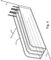
- Figs 3 and 4 are the cooling fins of a transformer. Since this is for a painting process each face of the transformer fins 14 is scanned separately from the other faces that are on the transformer fins 14 and the painting occurs only after all of the faces are scanned and the images from these scans are processed.
- Fig. 4 shows the transformer cooling fins 14 that are scanned by the camera.
- the lines in Fig. 4 marked as X, Y and Z are the coordinate frame.
- the transformer cooling fins 14 are recognized and located with computer vision techniques such as 3D segmentation, 3D planar fitting, 3D clustering, 3D grouping and sorting.
- the end result, as described below in more detail, of processing the images of the transformer cooling fins 14 acquired from the scan is the generation of the path that the robot 12 follows to paint the cooling fins 14 with the paint gun 16.
- the 3D scan is used to calculate the geometric elements for the cooling fins 14 such as width, height, the distances between the fins 14 and the normal directions to the fins 14.
- the geometric information together with the pre-known process parameters are used to generate the robot program for the path for painting above and in between fins 14.
- the first step 502 in flowchart 500 is the scanning the surface of the part 14 that will have work performed on it by the robot 12.
- the scanning is accomplished by moving the 3D camera around the part 14 and acquiring 3D images.
- the images are processed together by using either:
- the result of the scanning is the surface of the scanned area.
- the surface in the simplest form is a 3D point cloud.
- geometric information of interest for the scanned surface area is generated such as: a) extracting 3D geometric primitives from the surface as planes, corners, cylinders, cones, etc.; and b) extracting other geometric information of interest such as: distances between geometric entities, normals/directions, etc.
- a computing machine such as the robot controller 15 shown in Fig. 1 or a PC, etc. generates at step 506 the robot path program using the reference process parameters shown symbolically as 508. For painting these parameters are when to switch on paint flow, paint spray pattern, speed of robot motion, etc.
- the parameters are stored in the computing machine.
- the generated robot program is optionally verified at query 510 for quality. For example, is the entire path reachable and collision free and for painting can the right amount of paint material be deposited on the part 14 to be painted. If at optional step 510 the quality is not met for the robot program, then the robot program is re-generated again at 506 considering the information provided by the quality verification.
- step 512 the method is repeated to scan the next surface segment of the part 14 to be painted.
- the method is repeated to scan the next surface segment of the part 14 to be painted.
- each surface may be scanned and have worked performed on it before the next surface is scanned and worked on.
- the paths for each surface segment to be painted are stored on the robot controller 15 or on the PC before they are sent to the robot for execution. This allows, for example, the speed of the paint tool 16 along a narrow corner to be optimized so that the surface of the corner is not over-deposited with paint when the robot executes the path.
- the steps 602 to 610 of the method 600 shown in the flowchart in Fig. 6 are identical to the steps 502 to 510 with the exception that the process instructions are at step 608 generated along with the generation of the motion instructions for the robot path.
- the process instructions can be start and stop paint equipment, set paint flow speeds, or for other processes, contact forces range, speed for robot and external axes etc. While not shown in Fig. 6 for ease of illustration, there can be in the method 600 two blocks that are identical in function to blocks 514 and 516 described above.
- the flowchart of Fig. 7 for the method 700 has a scan surface step 702 that is identical to the steps 502 and 602 of Figs. 5 and 6 .
- the method proceeds to the step 704 wherein the generated geometric information for the scanned surface can be validated by comparing the scanned information with the reference geometric information in block 706 which may not be available. Since the reference geometric information may not be available, block 706 and the use of the reference geometric information for validation are both shown in Fig. 7 by dotted lines.
- the reference geometric information if available is used mostly in correlation with an existing reference robot path. If the reference geometric information doesn't exist, then the method 700 is identical to the methods 500 and 600 in Figs. 5 and 6 up to step 704.
- the validation in step 704 if performed is used to ensure that the surface that was scanned is the surface that should have been scanned and to determine if the geometric information generated from the scan correlates with the reference geometric information for that surface.
- the surface difference can be used further down the flow 700 in generating the robot path.
- the next step 708 generates the robot path using the geometric information generated in step 704 and the reference process parameters 710.
- the robot path 708 and process information 714 are generated only for the surface difference as the reference geometric information and reference robot path form a pair. If the surface that was scanned is the surface that should have been scanned, then only the process information is generated at step 714 as the robot path already exists. In this case, the generate robot path step 708 is a copy function.
- Fig. 7 shows a reference robot path 712.
- Path 712 is associated with the reference geometric information 706. Since the reference geometric information 706 may not be available, the reference robot path 712 is also shown by dotted lines in Fig. 7 . If both the reference robot path 712 the reference geometric information 706 are available, then the generate robot path 708 can calculate an offset for the reference robot path 712. Based on the reference process parameters 710, the reference robot path 712 if available can be updated or a new robot path is generated at 708.
- the process parameters and the process instructions are generated.
- the generate process block 714 can if needed use some of the reference process parameters in block 710.
- the generate robot path 708 and the process parameters and instructions generated at step 714 can be executed in an internal loop so that the robot path and process is optimized. For example, if a process parameter such as the distance from the paint gun 16 to the surface is calculated automatically, then the robot path needs to be updated.
- the robot program generated at step 720 which is the combination of steps 708 and 714, is verified at optional, as shown by the dotted lines, step 716 for quality.
- the optional quality verification asks is the entire path reachable and collision free and for painting can the right amount of paint material be deposited on the part to be painted. If the quality of the robot program is not met, then the robot program is re-generated again at step 720 considering the information provided by the optional quality verification step 716.
- step 718 the method is repeated to scan the next surface segment of the part to be painted. While not shown in Fig. 7 for ease of illustration, there can be in the method 700 two blocks that are identical in function to blocks 514 and 516 described above.
- Fig. 8 shows a flowchart for the method 800 that has a scan surface step 802 and a generate geometric information step 804 that are identical to steps 502 and 504 and 602 and 604, respectively of Figs. 5 and 6 .
- Method 800 has a step 808 that is as is described below an expanded version of step 608 of Fig. 6 .
- Step 808 uses the process template 806 to generate the robot path plus instructions such as start/stop etc.
- step 808 has two internal steps, namely generate robot path 810 and decide process parameters 812.
- the robot path is generated and at step 812 a decision is made as to which of the robot parameters such as start/stop etc. will be used.
- Fig. 8 there is an internal loop between steps 810 and 812 since a change in the parameters to be used may affect the generated path.
- the optional "Quality Met?" query at step 814 performs the same function as that performed by the same query in blocks 510, 610 and 716 shown in Figs. 5 , 6 and 7 respectively. If the answer is that the quality has not been met, then the method returns to step 808 so that a new path can be generated.
- the robot path or the process parameters can be changed. Which is changed depends on the quality check criteria. For example, if there is too much paint sprayed over a surface then the speed is increased.
- step 816 since the path and process have both been created at the output of step 808 the robot executes the path and the process.
Landscapes
- Engineering & Computer Science (AREA)
- Robotics (AREA)
- Mechanical Engineering (AREA)
- Manipulator (AREA)
- Numerical Control (AREA)
Claims (5)
- Système (10) destiné à générer un trajet à suivre par un robot (12) lorsque ledit robot doit exécuter un traitement sur une pièce (14), ledit système comprenant :un dispositif informatique (13) contenant un code de programme pour faire fonctionner ledit robot et obtenir des informations relatives à ladite pièce ; etun système de vision (11) pour balayer ladite pièce pour en obtenir des images, lesdites images étant fournies audit dispositif informatique,ledit dispositif informatique traitant lesdites images pour obtenir des informations géométriques concernant ladite pièce que ledit dispositif informatique peut utiliser en combinaison avec des paramètres de traitement de référence stockés dans ledit dispositif informatique pour générer un code de programme pour un trajet à suivre par ledit robot afin d'exécuter ledit processus sur ladite pièce, ledit code de programme comprenant des instructions de mouvement à suivre par ledit robot pour exécuter ledit traitement sur ladite pièce, ledit dispositif informatique optimisant ledit code de programme pour ledit chemin et des instructions de mouvement à suivre par ledit robot pour exécuter ledit processus sur ladite pièce,le système comprenant en outre :des informations géométriques de référence concernant ladite pièce qui sont utilisées par ledit dispositif informatique pour valider lesdites informations géométriques concernant ladite pièce obtenues en traitant lesdites images provenant dudit système de vision ;des informations de trajet de robot de référence associées aux informations géométriques de référence utilisées par ledit dispositif informatique et conjointement avec lesdites informations géométriques de référence pour calculer, lors de la génération dudit trajet à suivre par ledit robot lors de l'exécution dudit processus sur ladite pièce, un décalage pour ledit trajet de robot de référence uniquement en cas de différences géométriques entre les informations géométriques et les informations géométriques de référence, ledit trajet de robot correspondant au trajet de robot de référence associé aux informations géométriques de référence en l'absence desdites différences géométriques entre les informations géométriques et les informations géométriques de référence.
- Système (10) selon la revendication 1, dans lequel ledit dispositif informatique (13) comprend en outre un code configuré pour vérifier la qualité dudit code de programme généré pour lesdites instructions de trajet et de mouvement à suivre par ledit robot (12) pour exécuter ledit processus sur ladite pièce (14), ladite vérification de la qualité comprenant la vérification des collisions et/ou de l'accessibilité de l'intégralité du trajet.
- Système (10) selon la revendication 1, dans lequel ladite pièce (14) comprend deux ou plusieurs segments de surface, ledit processus étant exécuté sur chacun desdits deux segments de surface ou plus et ledit dispositif informatique (13) comprenant en outre un code configuré pour déterminer si tous lesdits deux segments de surface de pièce ou plus ont été balayés par ledit système de vision.
- Système (10) selon la revendication 3, dans lequel ledit robot (12) exécute ledit processus sur ladite pièce à l'aide dudit trajet à suivre par ledit robot pour exécuter ledit processus sur ladite pièce (14) lorsque tous lesdits deux segments de surfaces ou plus ont été balayés par ledit système de vision.
- Système (10) selon la revendication 3, dans lequel ledit dispositif informatique comprend en outre un code configuré pour amener ledit système de vision (11), lorsqu'il est déterminé que tous lesdits deux ou plusieurs segments de surface n'ont pas été tous balayés par ledit système de vision, à balayer un desdits deux segments de surface ou plus non balayé.
Applications Claiming Priority (2)
| Application Number | Priority Date | Filing Date | Title |
|---|---|---|---|
| US201261735300P | 2012-12-10 | 2012-12-10 | |
| PCT/US2013/073463 WO2014093144A1 (fr) | 2012-12-10 | 2013-12-06 | Génération de programme de robot pour processus robotiques |
Publications (2)
| Publication Number | Publication Date |
|---|---|
| EP2928648A1 EP2928648A1 (fr) | 2015-10-14 |
| EP2928648B1 true EP2928648B1 (fr) | 2019-12-04 |
Family
ID=50023838
Family Applications (1)
| Application Number | Title | Priority Date | Filing Date |
|---|---|---|---|
| EP13824547.7A Active EP2928648B1 (fr) | 2012-12-10 | 2013-12-06 | Génération de programme de robot pour processus robotiques |
Country Status (3)
| Country | Link |
|---|---|
| US (1) | US10427300B2 (fr) |
| EP (1) | EP2928648B1 (fr) |
| WO (1) | WO2014093144A1 (fr) |
Families Citing this family (20)
| Publication number | Priority date | Publication date | Assignee | Title |
|---|---|---|---|---|
| DE102013004144B4 (de) | 2013-03-09 | 2022-09-15 | Eisenmann Se | Verfahren und Vorrichtung zur Oberflächenbehandlung von Gegenständen |
| US10359760B2 (en) * | 2015-04-13 | 2019-07-23 | Michael Scott, JR. | Adaptable machining method and system |
| TWM523536U (zh) * | 2015-11-05 | 2016-06-11 | 發得科技工業股份有限公司 | 物件毛邊加工機 |
| CN106541404B (zh) * | 2016-11-03 | 2018-11-20 | 四川阿泰因机器人智能装备有限公司 | 一种机器人视觉定位导航方法 |
| US10583905B2 (en) | 2016-12-07 | 2020-03-10 | Abb Power Grids Switzerland Ag | Submersible drone having active ballast system |
| US10442117B2 (en) * | 2017-04-17 | 2019-10-15 | Indian Institute Of Technology Bombay | Laser based tyre mold vent cleaning process and device |
| CN107511848A (zh) * | 2017-08-30 | 2017-12-26 | 埃伏斯智能科技(上海)有限公司 | 一种工业机器人智能跟踪系统 |
| DE102017011252A1 (de) * | 2017-12-06 | 2019-06-06 | Kuka Deutschland Gmbh | Verfahren und System zur Bauteilbearbeitung durch Roboter |
| JP2021154392A (ja) * | 2018-05-22 | 2021-10-07 | ソニーグループ株式会社 | ロボットの制御装置及びロボットの制御方法 |
| DE102018113122A1 (de) * | 2018-06-01 | 2019-12-05 | Mack Rides Gmbh & Co Kg | Verfahren zum Facettieren sowie Vorrichtung für ein solches Verfahren |
| US11407111B2 (en) | 2018-06-27 | 2022-08-09 | Abb Schweiz Ag | Method and system to generate a 3D model for a robot scene |
| CN109513557B (zh) * | 2018-12-27 | 2024-05-24 | 海安科大机器人科技有限公司 | 一种基于视觉引导的船舶分段喷涂机器人自主喷涂方法 |
| DE102019111760A1 (de) * | 2019-05-07 | 2020-11-12 | Dürr Systems Ag | Beschichtungsverfahren und entsprechende Beschichtungsanlage |
| CN110103223A (zh) * | 2019-05-27 | 2019-08-09 | 西安交通大学 | 一种基于视觉识别的自动跟随避障方法及机器人 |
| US12372939B2 (en) | 2019-06-28 | 2025-07-29 | Corning Incorporated | Manufacturing a workpiece using optical dimensioning |
| US11826908B2 (en) | 2020-04-27 | 2023-11-28 | Scalable Robotics Inc. | Process agnostic robot teaching using 3D scans |
| US20220032461A1 (en) * | 2020-07-31 | 2022-02-03 | GrayMatter Robotics Inc. | Method to incorporate complex physical constraints in path-constrained trajectory planning for serial-link manipulator |
| CN112099775B (zh) * | 2020-09-15 | 2023-09-01 | 上海岭先机器人科技股份有限公司 | 一种制衣工艺流程代码化的方法 |
| EP4399672A4 (fr) | 2021-09-07 | 2025-08-13 | Scalable Robotics Inc | Système et procédé d'enseignement d'un programme robotisé |
| CN114178594B (zh) * | 2021-12-10 | 2022-12-23 | 上海交通大学 | 含偏差筒形薄壁铸件内腔铣削加工系统及加工方法 |
Family Cites Families (8)
| Publication number | Priority date | Publication date | Assignee | Title |
|---|---|---|---|---|
| US5429682A (en) * | 1993-08-19 | 1995-07-04 | Advanced Robotics Technologies | Automated three-dimensional precision coatings application apparatus |
| US6445964B1 (en) * | 1997-08-04 | 2002-09-03 | Harris Corporation | Virtual reality simulation-based training of telekinegenesis system for training sequential kinematic behavior of automated kinematic machine |
| WO2000025185A1 (fr) * | 1998-10-27 | 2000-05-04 | Irobotics, Inc. | Planification de processus robotises utilisant des gabarits |
| US6597967B2 (en) * | 2001-02-28 | 2003-07-22 | Board Of Trustees Operating Michigan State University | System and method for planning a tool path along a contoured surface |
| ITMI20050627A1 (it) * | 2005-04-13 | 2006-10-14 | Abb Service Srl | Metodo per la verniciatura di un oggetto e relativo impianto di verniciatura |
| CN106994684B (zh) * | 2009-02-03 | 2021-04-09 | 范努克机器人技术美国有限公司 | 控制机器人工具的方法 |
| WO2011004584A1 (fr) * | 2009-07-06 | 2011-01-13 | 三菱電機株式会社 | Dispositif et procédé de programmation automatique |
| US20120156362A1 (en) * | 2010-12-21 | 2012-06-21 | Alexandr Sadovoy | Method and device for coating path generation |
-
2013
- 2013-12-06 EP EP13824547.7A patent/EP2928648B1/fr active Active
- 2013-12-06 WO PCT/US2013/073463 patent/WO2014093144A1/fr not_active Ceased
- 2013-12-06 US US14/650,112 patent/US10427300B2/en active Active
Non-Patent Citations (1)
| Title |
|---|
| None * |
Also Published As
| Publication number | Publication date |
|---|---|
| US10427300B2 (en) | 2019-10-01 |
| EP2928648A1 (fr) | 2015-10-14 |
| US20150328773A1 (en) | 2015-11-19 |
| WO2014093144A1 (fr) | 2014-06-19 |
Similar Documents
| Publication | Publication Date | Title |
|---|---|---|
| EP2928648B1 (fr) | Génération de programme de robot pour processus robotiques | |
| CN105354880B (zh) | 一种基于线激光扫描的喷砂机器人自动路径生成方法 | |
| CN111192307B (zh) | 基于激光切割三维零部件的自适应纠偏方法 | |
| Maric et al. | Collaborative human-robot framework for delicate sanding of complex shape surfaces | |
| CN104126157B (zh) | 干涉检查装置及数控装置 | |
| CN111013883A (zh) | 一种可用于多车型的智能喷涂的机器人控制方法 | |
| Kuss et al. | Detection of workpiece shape deviations for tool path adaptation in robotic deburring systems | |
| CN107530881B (zh) | 机器人系统和用于操作机器人的方法 | |
| Lu et al. | A multi-sensor approach for rapid and precise digitization of free-form surface in reverse engineering | |
| CN114055255A (zh) | 一种基于实时点云的大型复杂构件表面打磨路径规划方法 | |
| Princely et al. | Vision assisted robotic deburring of edge burrs in cast parts | |
| Villagrossi et al. | Flexible robot-based cast iron deburring cell for small batch production using single-point laser sensor | |
| EP3229208B1 (fr) | Estimation de poses de caméra | |
| US20210283782A1 (en) | Measurement parameter optimization method and device, and computer control program stored on computer-readable storage medium | |
| KR102096897B1 (ko) | 3d 도면 파일을 이용하여 로봇 제어에 필요한 자동 티칭 시스템 및 티칭 방법 | |
| US20240042605A1 (en) | Apparatus and a Method for Automatically Programming a Robot to Follow Contours of Objects | |
| US6597967B2 (en) | System and method for planning a tool path along a contoured surface | |
| CN120800298A (zh) | 一种非接触式零件圆弧参数高精度测量方法及系统 | |
| Lee et al. | Implementation of a robotic arm with 3D vision for shoes glue spraying system | |
| Arntz et al. | Computer aided manufacturing supported process planning of additive manufacturing by laser deposition welding | |
| Penttilä et al. | Virtual reality enabled manufacturing of challenging workpieces | |
| Vincze et al. | Automatic robotic spray painting of low volume high variant parts | |
| Suszyński et al. | No Clamp Robotic Assembly with Use of Point Cloud Data from Low-Cost Triangulation Scanner | |
| CN106271235B (zh) | 基于机器视觉的焊道定位方法及装置 | |
| Saukkoriipi | Design and implementation of robot skill programming and control |
Legal Events
| Date | Code | Title | Description |
|---|---|---|---|
| PUAI | Public reference made under article 153(3) epc to a published international application that has entered the european phase |
Free format text: ORIGINAL CODE: 0009012 |
|
| 17P | Request for examination filed |
Effective date: 20150611 |
|
| AK | Designated contracting states |
Kind code of ref document: A1 Designated state(s): AL AT BE BG CH CY CZ DE DK EE ES FI FR GB GR HR HU IE IS IT LI LT LU LV MC MK MT NL NO PL PT RO RS SE SI SK SM TR |
|
| AX | Request for extension of the european patent |
Extension state: BA ME |
|
| DAX | Request for extension of the european patent (deleted) | ||
| STAA | Information on the status of an ep patent application or granted ep patent |
Free format text: STATUS: EXAMINATION IS IN PROGRESS |
|
| 17Q | First examination report despatched |
Effective date: 20190401 |
|
| GRAP | Despatch of communication of intention to grant a patent |
Free format text: ORIGINAL CODE: EPIDOSNIGR1 |
|
| STAA | Information on the status of an ep patent application or granted ep patent |
Free format text: STATUS: GRANT OF PATENT IS INTENDED |
|
| INTG | Intention to grant announced |
Effective date: 20190909 |
|
| GRAS | Grant fee paid |
Free format text: ORIGINAL CODE: EPIDOSNIGR3 |
|
| GRAA | (expected) grant |
Free format text: ORIGINAL CODE: 0009210 |
|
| STAA | Information on the status of an ep patent application or granted ep patent |
Free format text: STATUS: THE PATENT HAS BEEN GRANTED |
|
| RAP1 | Party data changed (applicant data changed or rights of an application transferred) |
Owner name: ABB SCHWEIZ AG |
|
| AK | Designated contracting states |
Kind code of ref document: B1 Designated state(s): AL AT BE BG CH CY CZ DE DK EE ES FI FR GB GR HR HU IE IS IT LI LT LU LV MC MK MT NL NO PL PT RO RS SE SI SK SM TR |
|
| REG | Reference to a national code |
Ref country code: GB Ref legal event code: FG4D |
|
| REG | Reference to a national code |
Ref country code: CH Ref legal event code: EP |
|
| REG | Reference to a national code |
Ref country code: AT Ref legal event code: REF Ref document number: 1208801 Country of ref document: AT Kind code of ref document: T Effective date: 20191215 |
|
| REG | Reference to a national code |
Ref country code: DE Ref legal event code: R096 Ref document number: 602013063678 Country of ref document: DE |
|
| REG | Reference to a national code |
Ref country code: IE Ref legal event code: FG4D |
|
| REG | Reference to a national code |
Ref country code: NL Ref legal event code: MP Effective date: 20191204 |
|
| REG | Reference to a national code |
Ref country code: LT Ref legal event code: MG4D |
|
| PG25 | Lapsed in a contracting state [announced via postgrant information from national office to epo] |
Ref country code: SE Free format text: LAPSE BECAUSE OF FAILURE TO SUBMIT A TRANSLATION OF THE DESCRIPTION OR TO PAY THE FEE WITHIN THE PRESCRIBED TIME-LIMIT Effective date: 20191204 Ref country code: LT Free format text: LAPSE BECAUSE OF FAILURE TO SUBMIT A TRANSLATION OF THE DESCRIPTION OR TO PAY THE FEE WITHIN THE PRESCRIBED TIME-LIMIT Effective date: 20191204 Ref country code: FI Free format text: LAPSE BECAUSE OF FAILURE TO SUBMIT A TRANSLATION OF THE DESCRIPTION OR TO PAY THE FEE WITHIN THE PRESCRIBED TIME-LIMIT Effective date: 20191204 Ref country code: BG Free format text: LAPSE BECAUSE OF FAILURE TO SUBMIT A TRANSLATION OF THE DESCRIPTION OR TO PAY THE FEE WITHIN THE PRESCRIBED TIME-LIMIT Effective date: 20200304 Ref country code: GR Free format text: LAPSE BECAUSE OF FAILURE TO SUBMIT A TRANSLATION OF THE DESCRIPTION OR TO PAY THE FEE WITHIN THE PRESCRIBED TIME-LIMIT Effective date: 20200305 Ref country code: LV Free format text: LAPSE BECAUSE OF FAILURE TO SUBMIT A TRANSLATION OF THE DESCRIPTION OR TO PAY THE FEE WITHIN THE PRESCRIBED TIME-LIMIT Effective date: 20191204 Ref country code: NO Free format text: LAPSE BECAUSE OF FAILURE TO SUBMIT A TRANSLATION OF THE DESCRIPTION OR TO PAY THE FEE WITHIN THE PRESCRIBED TIME-LIMIT Effective date: 20200304 |
|
| PG25 | Lapsed in a contracting state [announced via postgrant information from national office to epo] |
Ref country code: RS Free format text: LAPSE BECAUSE OF FAILURE TO SUBMIT A TRANSLATION OF THE DESCRIPTION OR TO PAY THE FEE WITHIN THE PRESCRIBED TIME-LIMIT Effective date: 20191204 Ref country code: HR Free format text: LAPSE BECAUSE OF FAILURE TO SUBMIT A TRANSLATION OF THE DESCRIPTION OR TO PAY THE FEE WITHIN THE PRESCRIBED TIME-LIMIT Effective date: 20191204 |
|
| PG25 | Lapsed in a contracting state [announced via postgrant information from national office to epo] |
Ref country code: AL Free format text: LAPSE BECAUSE OF FAILURE TO SUBMIT A TRANSLATION OF THE DESCRIPTION OR TO PAY THE FEE WITHIN THE PRESCRIBED TIME-LIMIT Effective date: 20191204 |
|
| PG25 | Lapsed in a contracting state [announced via postgrant information from national office to epo] |
Ref country code: CZ Free format text: LAPSE BECAUSE OF FAILURE TO SUBMIT A TRANSLATION OF THE DESCRIPTION OR TO PAY THE FEE WITHIN THE PRESCRIBED TIME-LIMIT Effective date: 20191204 Ref country code: RO Free format text: LAPSE BECAUSE OF FAILURE TO SUBMIT A TRANSLATION OF THE DESCRIPTION OR TO PAY THE FEE WITHIN THE PRESCRIBED TIME-LIMIT Effective date: 20191204 Ref country code: ES Free format text: LAPSE BECAUSE OF FAILURE TO SUBMIT A TRANSLATION OF THE DESCRIPTION OR TO PAY THE FEE WITHIN THE PRESCRIBED TIME-LIMIT Effective date: 20191204 Ref country code: EE Free format text: LAPSE BECAUSE OF FAILURE TO SUBMIT A TRANSLATION OF THE DESCRIPTION OR TO PAY THE FEE WITHIN THE PRESCRIBED TIME-LIMIT Effective date: 20191204 Ref country code: NL Free format text: LAPSE BECAUSE OF FAILURE TO SUBMIT A TRANSLATION OF THE DESCRIPTION OR TO PAY THE FEE WITHIN THE PRESCRIBED TIME-LIMIT Effective date: 20191204 Ref country code: PT Free format text: LAPSE BECAUSE OF FAILURE TO SUBMIT A TRANSLATION OF THE DESCRIPTION OR TO PAY THE FEE WITHIN THE PRESCRIBED TIME-LIMIT Effective date: 20200429 |
|
| REG | Reference to a national code |
Ref country code: CH Ref legal event code: PL |
|
| REG | Reference to a national code |
Ref country code: BE Ref legal event code: MM Effective date: 20191231 |
|
| PG25 | Lapsed in a contracting state [announced via postgrant information from national office to epo] |
Ref country code: IS Free format text: LAPSE BECAUSE OF FAILURE TO SUBMIT A TRANSLATION OF THE DESCRIPTION OR TO PAY THE FEE WITHIN THE PRESCRIBED TIME-LIMIT Effective date: 20200404 Ref country code: SK Free format text: LAPSE BECAUSE OF FAILURE TO SUBMIT A TRANSLATION OF THE DESCRIPTION OR TO PAY THE FEE WITHIN THE PRESCRIBED TIME-LIMIT Effective date: 20191204 Ref country code: SM Free format text: LAPSE BECAUSE OF FAILURE TO SUBMIT A TRANSLATION OF THE DESCRIPTION OR TO PAY THE FEE WITHIN THE PRESCRIBED TIME-LIMIT Effective date: 20191204 |
|
| REG | Reference to a national code |
Ref country code: DE Ref legal event code: R097 Ref document number: 602013063678 Country of ref document: DE |
|
| REG | Reference to a national code |
Ref country code: AT Ref legal event code: MK05 Ref document number: 1208801 Country of ref document: AT Kind code of ref document: T Effective date: 20191204 |
|
| PG25 | Lapsed in a contracting state [announced via postgrant information from national office to epo] |
Ref country code: MC Free format text: LAPSE BECAUSE OF FAILURE TO SUBMIT A TRANSLATION OF THE DESCRIPTION OR TO PAY THE FEE WITHIN THE PRESCRIBED TIME-LIMIT Effective date: 20191204 |
|
| PLBE | No opposition filed within time limit |
Free format text: ORIGINAL CODE: 0009261 |
|
| STAA | Information on the status of an ep patent application or granted ep patent |
Free format text: STATUS: NO OPPOSITION FILED WITHIN TIME LIMIT |
|
| PG25 | Lapsed in a contracting state [announced via postgrant information from national office to epo] |
Ref country code: DK Free format text: LAPSE BECAUSE OF FAILURE TO SUBMIT A TRANSLATION OF THE DESCRIPTION OR TO PAY THE FEE WITHIN THE PRESCRIBED TIME-LIMIT Effective date: 20191204 Ref country code: IE Free format text: LAPSE BECAUSE OF NON-PAYMENT OF DUE FEES Effective date: 20191206 Ref country code: LU Free format text: LAPSE BECAUSE OF NON-PAYMENT OF DUE FEES Effective date: 20191206 |
|
| 26N | No opposition filed |
Effective date: 20200907 |
|
| PG25 | Lapsed in a contracting state [announced via postgrant information from national office to epo] |
Ref country code: LI Free format text: LAPSE BECAUSE OF NON-PAYMENT OF DUE FEES Effective date: 20191231 Ref country code: AT Free format text: LAPSE BECAUSE OF FAILURE TO SUBMIT A TRANSLATION OF THE DESCRIPTION OR TO PAY THE FEE WITHIN THE PRESCRIBED TIME-LIMIT Effective date: 20191204 Ref country code: PL Free format text: LAPSE BECAUSE OF FAILURE TO SUBMIT A TRANSLATION OF THE DESCRIPTION OR TO PAY THE FEE WITHIN THE PRESCRIBED TIME-LIMIT Effective date: 20191204 Ref country code: SI Free format text: LAPSE BECAUSE OF FAILURE TO SUBMIT A TRANSLATION OF THE DESCRIPTION OR TO PAY THE FEE WITHIN THE PRESCRIBED TIME-LIMIT Effective date: 20191204 Ref country code: BE Free format text: LAPSE BECAUSE OF NON-PAYMENT OF DUE FEES Effective date: 20191231 Ref country code: CH Free format text: LAPSE BECAUSE OF NON-PAYMENT OF DUE FEES Effective date: 20191231 |
|
| GBPC | Gb: european patent ceased through non-payment of renewal fee |
Effective date: 20200304 |
|
| PG25 | Lapsed in a contracting state [announced via postgrant information from national office to epo] |
Ref country code: GB Free format text: LAPSE BECAUSE OF NON-PAYMENT OF DUE FEES Effective date: 20200304 |
|
| PG25 | Lapsed in a contracting state [announced via postgrant information from national office to epo] |
Ref country code: CY Free format text: LAPSE BECAUSE OF FAILURE TO SUBMIT A TRANSLATION OF THE DESCRIPTION OR TO PAY THE FEE WITHIN THE PRESCRIBED TIME-LIMIT Effective date: 20191204 |
|
| PG25 | Lapsed in a contracting state [announced via postgrant information from national office to epo] |
Ref country code: HU Free format text: LAPSE BECAUSE OF FAILURE TO SUBMIT A TRANSLATION OF THE DESCRIPTION OR TO PAY THE FEE WITHIN THE PRESCRIBED TIME-LIMIT; INVALID AB INITIO Effective date: 20131206 Ref country code: MT Free format text: LAPSE BECAUSE OF FAILURE TO SUBMIT A TRANSLATION OF THE DESCRIPTION OR TO PAY THE FEE WITHIN THE PRESCRIBED TIME-LIMIT Effective date: 20191204 |
|
| PG25 | Lapsed in a contracting state [announced via postgrant information from national office to epo] |
Ref country code: TR Free format text: LAPSE BECAUSE OF FAILURE TO SUBMIT A TRANSLATION OF THE DESCRIPTION OR TO PAY THE FEE WITHIN THE PRESCRIBED TIME-LIMIT Effective date: 20191204 |
|
| PG25 | Lapsed in a contracting state [announced via postgrant information from national office to epo] |
Ref country code: MK Free format text: LAPSE BECAUSE OF FAILURE TO SUBMIT A TRANSLATION OF THE DESCRIPTION OR TO PAY THE FEE WITHIN THE PRESCRIBED TIME-LIMIT Effective date: 20191204 |
|
| PGFP | Annual fee paid to national office [announced via postgrant information from national office to epo] |
Ref country code: DE Payment date: 20251211 Year of fee payment: 13 |
|
| PGFP | Annual fee paid to national office [announced via postgrant information from national office to epo] |
Ref country code: IT Payment date: 20251223 Year of fee payment: 13 |
|
| PGFP | Annual fee paid to national office [announced via postgrant information from national office to epo] |
Ref country code: FR Payment date: 20251223 Year of fee payment: 13 |