EP2929191B1 - Kreiselpumpe insbesondere für abwasser oder schmutzwasser - Google Patents
Kreiselpumpe insbesondere für abwasser oder schmutzwasser Download PDFInfo
- Publication number
- EP2929191B1 EP2929191B1 EP13805772.4A EP13805772A EP2929191B1 EP 2929191 B1 EP2929191 B1 EP 2929191B1 EP 13805772 A EP13805772 A EP 13805772A EP 2929191 B1 EP2929191 B1 EP 2929191B1
- Authority
- EP
- European Patent Office
- Prior art keywords
- base plate
- impeller
- rotary pump
- pump according
- intake opening
- Prior art date
- Legal status (The legal status is an assumption and is not a legal conclusion. Google has not performed a legal analysis and makes no representation as to the accuracy of the status listed.)
- Active
Links
Images




Classifications
-
- F—MECHANICAL ENGINEERING; LIGHTING; HEATING; WEAPONS; BLASTING
- F04—POSITIVE - DISPLACEMENT MACHINES FOR LIQUIDS; PUMPS FOR LIQUIDS OR ELASTIC FLUIDS
- F04D—NON-POSITIVE-DISPLACEMENT PUMPS
- F04D29/00—Details, component parts, or accessories
- F04D29/40—Casings; Connections of working fluid
- F04D29/42—Casings; Connections of working fluid for radial or helico-centrifugal pumps
- F04D29/44—Fluid-guiding means, e.g. diffusers
- F04D29/46—Fluid-guiding means, e.g. diffusers adjustable
- F04D29/466—Fluid-guiding means, e.g. diffusers adjustable especially adapted for liquid fluid pumps
-
- F—MECHANICAL ENGINEERING; LIGHTING; HEATING; WEAPONS; BLASTING
- F04—POSITIVE - DISPLACEMENT MACHINES FOR LIQUIDS; PUMPS FOR LIQUIDS OR ELASTIC FLUIDS
- F04D—NON-POSITIVE-DISPLACEMENT PUMPS
- F04D7/00—Pumps adapted for handling specific fluids, e.g. by selection of specific materials for pumps or pump parts
- F04D7/02—Pumps adapted for handling specific fluids, e.g. by selection of specific materials for pumps or pump parts of centrifugal type
- F04D7/04—Pumps adapted for handling specific fluids, e.g. by selection of specific materials for pumps or pump parts of centrifugal type the fluids being viscous or non-homogenous
-
- F—MECHANICAL ENGINEERING; LIGHTING; HEATING; WEAPONS; BLASTING
- F04—POSITIVE - DISPLACEMENT MACHINES FOR LIQUIDS; PUMPS FOR LIQUIDS OR ELASTIC FLUIDS
- F04D—NON-POSITIVE-DISPLACEMENT PUMPS
- F04D1/00—Radial-flow pumps, e.g. centrifugal pumps; Helico-centrifugal pumps
-
- F—MECHANICAL ENGINEERING; LIGHTING; HEATING; WEAPONS; BLASTING
- F04—POSITIVE - DISPLACEMENT MACHINES FOR LIQUIDS; PUMPS FOR LIQUIDS OR ELASTIC FLUIDS
- F04D—NON-POSITIVE-DISPLACEMENT PUMPS
- F04D13/00—Pumping installations or systems
- F04D13/02—Units comprising pumps and their driving means
- F04D13/06—Units comprising pumps and their driving means the pump being electrically driven
- F04D13/08—Units comprising pumps and their driving means the pump being electrically driven for submerged use
-
- F—MECHANICAL ENGINEERING; LIGHTING; HEATING; WEAPONS; BLASTING
- F04—POSITIVE - DISPLACEMENT MACHINES FOR LIQUIDS; PUMPS FOR LIQUIDS OR ELASTIC FLUIDS
- F04D—NON-POSITIVE-DISPLACEMENT PUMPS
- F04D15/00—Control, e.g. regulation, of pumps, pumping installations or systems
- F04D15/0027—Varying behaviour or the very pump
- F04D15/0033—By-passing by increasing clearance between impeller and its casing
-
- F—MECHANICAL ENGINEERING; LIGHTING; HEATING; WEAPONS; BLASTING
- F04—POSITIVE - DISPLACEMENT MACHINES FOR LIQUIDS; PUMPS FOR LIQUIDS OR ELASTIC FLUIDS
- F04D—NON-POSITIVE-DISPLACEMENT PUMPS
- F04D29/00—Details, component parts, or accessories
- F04D29/26—Rotors specially for elastic fluids
- F04D29/28—Rotors specially for elastic fluids for centrifugal or helico-centrifugal pumps for radial-flow or helico-centrifugal pumps
- F04D29/30—Vanes
-
- F—MECHANICAL ENGINEERING; LIGHTING; HEATING; WEAPONS; BLASTING
- F04—POSITIVE - DISPLACEMENT MACHINES FOR LIQUIDS; PUMPS FOR LIQUIDS OR ELASTIC FLUIDS
- F04D—NON-POSITIVE-DISPLACEMENT PUMPS
- F04D29/00—Details, component parts, or accessories
- F04D29/40—Casings; Connections of working fluid
- F04D29/42—Casings; Connections of working fluid for radial or helico-centrifugal pumps
- F04D29/426—Casings; Connections of working fluid for radial or helico-centrifugal pumps especially adapted for liquid pumps
-
- F—MECHANICAL ENGINEERING; LIGHTING; HEATING; WEAPONS; BLASTING
- F04—POSITIVE - DISPLACEMENT MACHINES FOR LIQUIDS; PUMPS FOR LIQUIDS OR ELASTIC FLUIDS
- F04D—NON-POSITIVE-DISPLACEMENT PUMPS
- F04D29/00—Details, component parts, or accessories
- F04D29/60—Mounting; Assembling; Disassembling
- F04D29/62—Mounting; Assembling; Disassembling of radial or helico-centrifugal pumps
- F04D29/622—Adjusting the clearances between rotary and stationary parts
-
- F—MECHANICAL ENGINEERING; LIGHTING; HEATING; WEAPONS; BLASTING
- F04—POSITIVE - DISPLACEMENT MACHINES FOR LIQUIDS; PUMPS FOR LIQUIDS OR ELASTIC FLUIDS
- F04D—NON-POSITIVE-DISPLACEMENT PUMPS
- F04D29/00—Details, component parts, or accessories
- F04D29/70—Suction grids; Strainers; Dust separation; Cleaning
- F04D29/708—Suction grids; Strainers; Dust separation; Cleaning specially for liquid pumps
-
- F—MECHANICAL ENGINEERING; LIGHTING; HEATING; WEAPONS; BLASTING
- F04—POSITIVE - DISPLACEMENT MACHINES FOR LIQUIDS; PUMPS FOR LIQUIDS OR ELASTIC FLUIDS
- F04D—NON-POSITIVE-DISPLACEMENT PUMPS
- F04D7/00—Pumps adapted for handling specific fluids, e.g. by selection of specific materials for pumps or pump parts
- F04D7/02—Pumps adapted for handling specific fluids, e.g. by selection of specific materials for pumps or pump parts of centrifugal type
Definitions
- the invention relates to a centrifugal pump, in particular a sewage or waste water motor pump with an impeller, the end face of which faces the pump suction opening is open and only the impeller end face facing away from the suction opening is covered by a circular coaxial support disk, to which the curved blades are attached, in particular, being molded on.
- Wastewater often contains coarse solids such as long-fiber admixtures that can clog a centrifugal pump.
- coarse solids such as long-fiber admixtures that can clog a centrifugal pump.
- the efficiency of such a low-clogging centrifugal pump is significantly reduced as a result.
- the object of the invention is to improve a centrifugal pump of the type mentioned at the outset in such a way that, with high pump efficiency, there is a high level of operational safety and a low risk of clogging.
- the base plate which has the suction opening and faces the impeller, or at least one segment thereof, is movably adjustable and / or deformable and / or movably supported against spring pressure such that its distance from the impeller and thus from the impeller blades Changes, whereby a construction with optimal mobility and adaptability to the degree of contamination is given when the base plate has a first region immovable or movably mounted on the pump housing and at least one second region movably and / or deformably supported on the first region and / or on the housing wall against spring pressure , Has plate-shaped area in the form of a segment, the movable second area being held by at least one screw with limited mobility on the fixed area and / or on the housing wall.
- Such a construction automatically adjusts the distance between the impeller and base plate to the degree of contamination and the size of the conveyed solids and / or can be optimally adjusted by adjusting accordingly.
- the base plate or the segment (s) of the base plate is / are mounted on the pump housing by at least one set screw.
- a particularly simple and stable construction is provided if the set screw (s) penetrates the base plate and lies with its head in a bore extension that opens towards the impeller.
- the set screw (s) be surrounded by a helical compression spring which generates the spring pressure on the base plate.
- the distance between the blades and the base plate increases from the blade leading edge to the blade leading edge. It is advantageous if the distance between the blades and the base plate is 0.5 to 2 mm.
- the impeller preferably has two curved blades.
- An advantageous embodiment consists in that the base plate is trough-shaped, in particular concave, on its side facing the impeller, and the height of the blades decreases towards the outside in accordance with the base plate curvature.
- a low-vibration rectilinear input flow is achieved if the suction opening has groove-shaped flow channels in its inner wall, which are preferably arranged parallel to the main flow direction in the suction opening. It is preferably proposed here that the inner wall of the suction opening is cylindrical and the flow channels are arranged axially parallel to the axis of the inner wall of the cylinder.
- the side wall that is last passed by a blade forms an inclined surface that widens the groove towards the outside.
- the centrifugal pump according to the invention is particularly suitable for pumping wastewater and dirty water that contains solid particles. It is preferably part of a submersible water pump.
- the pump impeller 1 is driven by the shaft of an electric motor, not shown, and is seated in a pump chamber which lies between a base plate 7 which forms the coaxial suction opening 8 and a partition wall which separates the electric motor from the pump chamber.
- the impeller 1 made of plastic or metal sucks in the pumping medium via the suction opening 8 and conveys it radially to the spiral channel 14, which is formed by the pump housing 13, surrounds the impeller and opens into the pump pressure connection.
- the base plate 7 is trough-shaped, in particular concave, on its side facing the impeller 1 and the height of the blades 3, 4 decreases outwards in accordance with the base plate curvature.
- the impeller 1 is a semi-open impeller, i. H. it has a circular support disk (cover disk) 2 on the side facing the partition 13 and has no front cover disk.
- the support disk On the surface facing the suction opening 8, the support disk carries two blades 3, 4 which are curved (in particular C-shaped), the concave surface of each blade 3, 4 facing the impeller axis.
- one, three or more blades can also be attached, in particular molded, to the support disk 2.
- the approximately C-shaped blades 3, 4 extend from the inside out to the edge of the impeller 1, the generatrix of the blade extending parallel or obliquely to the pump axis and thus to the impeller axis, so that each blade is perpendicular or oblique to the flat rear surface 2a of the support plate 2 is on the front side of the support plate 2b which rises to the center of the plate.
- the free front edge of each blade 3, 4 forms an elongated thickening 12, which in the exemplary embodiment Fig. 1 extends as a profile along the front edge, the profile having a triangular, polygonal or polygonal cross section with an inclined longitudinal surface facing the inner surface 7c of the base plate 7, which runs as a bevel 6 parallel to the surface 7c.
- the distance between the longitudinal surface / chamfer 6 and the surface 7ca is preferably 0.5 to 2 mm.
- the distance between the blades 3, 4 and the base plate 7 can increase from the blade leading edge to the blade leading edge.
- the elongated thickening 12 is not formed by a profile with a cross-section that remains the same over the length, but the thickening 12 is either only partially profile-shaped, in particular in sections, or its cross-section increases or decreases in size from one end to the other.
- the largest cross section of the elongated thickening 12 is always greater than the width or thickness D of the blade 3, 4.
- the thickening 12 projects on both or at least on one side of the blade.
- each blade 3, 4 which forms the leading edge of the blade, carries an elongated, in particular molded, thickening 9, which runs along the inner blade end 9a and in Fig. 2
- the embodiment shown is parallel to the impeller axis.
- at least one of the thickenings can also be arranged obliquely and thus at an acute angle to the impeller axis.
- both thickenings 9 are formed by profiles with a circular cross section.
- the profiles can also have differently shaped cross sections, in particular oval or elliptical ones.
- the cross section can change in shape and / or size, in particular sections, over its length.
- these are preferably formed from the material of the blade and thus from the same plastic or metal of the blade and are preferably molded on.
- the distance between the base plate 7 and the blades 3, 4 is adjustable, so that the pump can be adapted to the various admixtures in the waste water or dirty water. Either the height of the entire base plate is adjustable, or at least the area over which the blades pass. The adjustment takes place z. B. by thread, screws 16 or wedge surfaces by hand, in particular with tools, or motor, hydraulic or pneumatic, in particular computer-controlled and / or remote-controlled.
- the base plate 7 is attached to the pump housing 13 by means of set screws 16 which are arranged on the outer edge of the base plate, so that the distance of the base plate 7 from the impeller 1 can be adjusted from the outside.
- the base plate 7 lies within the pump housing 13, so that it is covered on the outside by the housing wall 13a.
- the base plate 7 has a central opening 7d, which is aligned with the suction opening 8 of the housing wall.
- the inner base plate 7 is supported by at least one, preferably three or four screws 16 on the housing wall, which surrounds the suction opening 8.
- Each screw 16 lies in a bore 17 in the base plate 7.
- the bore 17 has an extension 18 which opens towards the impeller and in which the screw head 21 lies.
- An extension 19 opening towards the base plate also has the threaded hole in the housing wall, in which extension 19 there is a helical compression spring 20 which rests on the underside of the base plate 7 in order to press the base plate in the direction of the impeller 1. Since there is a distance of several millimeters between the underside of the base plate 7 and the inside of the housing wall, the base plate can be downward (in Fig. 6 ) dodge if a larger solid part gets between the base plate and the outer blade edges of the impeller.
- Fig. 7 differs from that after Fig. 6 in that the bottom plate mounted on the inside has a first region 7a which is mounted immovably or movably on the pump housing, on which a second, in particular segment-shaped region 7b is movably supported against spring pressure and / or is held movably by means of elastic deformability of the component.
- the head 21 of the screw (s) lies in a bore extension 18 of the second plate-shaped, in particular segment-shaped region 7b, so that at least the second region or segment 7b can move away from the impeller 1 against the pressure of the spring 20 and / or deforms when larger solid particles get between the impeller blades and the plate-shaped segment 7b.
- the bottom plate 7 has, as in Fig. 3 shown, three in particular C-shaped grooves 10 which extend from the suction opening 8 and extend to the outer edge of the base plate 7 and are curved opposite to the curvature of the blades 3, 4.
- the grooves 10 support the conveying of the solids radially outwards, so that a self-cleaning effect occurs.
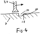
- the conveying to the outside is further enhanced by the fact that of the two side walls of the grooves 10, the side wall that is last passed over by a blade 3, 4 forms an inclined surface 15 that leads the groove outwards extended (see Fig. 4 ).
- the inclined surface 15 forms an angle ⁇ of 110 to 160 degrees with the surface of the base plate 7.
- one, two, four or more grooves can also be made in the base plate.
- the preferably cylindrical suction opening 8 has groove-shaped flow channels 11 in its inner wall, which are preferably arranged parallel to the main flow direction in the suction opening, so that the solids in the wastewater or dirty water are repelled to the impeller and the risk of clogging is reduced.
- the groove-shaped flow channels 11 are distributed at equal angular intervals over the inner wall of the suction opening.
- six flow channels 11 are shown. The number can also be smaller (3 to 5) or larger (7 to 12).
Landscapes
- Engineering & Computer Science (AREA)
- Mechanical Engineering (AREA)
- General Engineering & Computer Science (AREA)
- Structures Of Non-Positive Displacement Pumps (AREA)
Description
- Die Erfindung betrifft eine Kreiselpumpe insbesondere Abwasser- oder Schmutzwasser-Motorpumpe mit einem Laufrad, dessen der Pumpensaugöffnung zugewandte Stirnseite offen ist und nur die der Saugöffnung abgewandte Laufrad-Stirnseite durch eine kreisförmige koaxiale Tragscheibe bedeckt ist, an der die gekrümmten Schaufeln befestigt insbesondere angeformt sind.
- Abwässer enthalten oft grobe Feststoffe wie langfaserige Beimengungen, die eine Kreiselpumpe verstopfen können. Um diese Verstopfungsgefahr zu verringern, ist es bekannt, zwischen der die Saugöffnung aufweisenden Bodenplatte und dem Laufrad einen großen Abstand vorzusehen, so dass größere Feststoffteile seitlich am Laufrad vorbeiströmen, ohne dieses zu blockieren. Der Wirkungsgrad einer solchen verstopfungsarmen Kreiselpumpe ist hierdurch wesentlich verringert.
- Aus den Patentanmeldungen
FR 2681906 A1 EP 1538339 A1 ,WO 03/081050 A1 DE 19823603 A1 undDE 4142120 A1 sind jeweils Kreiselpumpen der eingangs genannten Gattung bekannt, bei der eine die Saugöffnung aufweisende, dem Laufrad zugewandte Bodenplatte beweglich am Pumpengehäuse gelagert ist. - Aufgabe der Erfindung ist es, eine Kreiselpumpe der eingangs genannten Art so zu verbessern, dass bei hohem Pumpenwirkungsgrad eine hohe Betriebssicherheit und eine geringe Verstopfungsgefahr bestehen.
- Diese Aufgabe wird erfindungsgemäß dadurch gelöst, dass die die Saugöffnung aufweisende, dem Laufrad zugewandte Bodenplatte oder mindestens ein Segment von ihr derart beweglich verstellbar und/oder verformbar und/oder gegen Federdruck beweglich gelagert ist, dass sich ihr Abstand zum Laufrad und damit zu den Laufradschaufeln ändert, wobei eine Konstruktion mit optimaler Beweglichkeit und Anpassungsfähigkeit an den Verschmutzungsgrad dann gegeben ist, wenn die Bodenplatte einen am Pumpengehäuse unbeweglichen oder beweglich gelagerten ersten Bereich und mindestens einen am ersten Bereich und/oder an der Gehäusewand gegen Federdruck beweglich gelagerten und/oder verformbaren zweiten, plattenförmigen Bereich in Form eines Segments aufweist, wobei der bewegliche zweite Bereich durch mindestens eine Schraube begrenzt beweglich am festen Bereich und/oder an der Gehäusewand gehalten ist.
- Durch eine solche Konstruktion passt sich der Abstand zwischen Laufrad und Bodenplatte selbstständig an den Verschmutzungsgrad und die Größe der geförderten Feststoffe an und/oder kann durch Verstellen entsprechend optimal angepasst werden.
- Hierzu wird vorgeschlagen, dass die Bodenplatte oder das/die Segment(e) der Bodenplatte durch mindestens eine Stellschraube an dem Pumpengehäuse gelagert ist/sind. Eine besonders einfache und stabile Konstruktion ist gegeben, wenn die Stellschraube(n) die Bodenplatte durchdringt/durchdringen und mit ihrem Kopf in einer Bohrungserweiterung einliegt/einliegen, die sich zum Laufrad hin öffnet.
- Vorzugsweise wird vorgeschlagen, dass die Stellschraube(n) von einer Schraubendruckfeder umgeben ist, die den Federdruck auf die Bodenplatte erzeugt.
- Vorzugsweise wird vorgeschlagen, dass der Abstand zwischen den Schaufeln und der Bodenplatte von der Schaufeleintrittskante bis zur Schaufelaustrittskante zunimmt. Von Vorteil ist, wenn der Abstand zwischen den Schaufeln und der Bodenplatte 0,5 bis 2 mm beträgt. Vorzugsweise weist das Laufrad zwei gekrümmte Schaufeln auf.
- Eine vorteilhafte Ausgestaltung besteht darin, dass die Bodenplatte auf ihrer dem Laufrad zugewandten Seite muldenförmig insbesondere konkav gewölbt ist und die Höhe der Schaufeln entsprechend der Bodenplattenwölbung nach außen hin abnimmt.
- Eine vibrationsarme geradlinige Eingangsströmung wird erreicht, wenn die Saugöffnung in ihrer Innenwand nutenförmige Strömungskanäle aufweist, die vorzugsweise parallel zur Haupt-Strömungsrichtung in der Saugöffnung angeordnet sind. Vorzugsweise wird hierbei vorgeschlagen, dass die Innenwand der Saugöffnung zylindrisch ist und die Strömungskanäle achsparallel zur Achse der Zylinderinnenwand angeordnet sind.
- Besonders vorteilhaft ist es,
- wenn die die Saugöffnung aufweisende Bodenplatte des Pumpengehäuses, über die die freien Kanten der Schaufeln in geringem Abstand hinwegstreichen, mindestens eine, vorzugsweise zwei, drei oder mehr insbesondere C-förmig gekrümmte Nuten aufweist,
- wenn die Nuten von der Saugöffnung ausgehen und sich bis zum Außenrand der Bodenplatte erstrecken, und
- wenn die Nuten entgegengesetzt der Krümmung der Schaufeln gekrümmt sind.
- Diese in der Bodenplatte eingebrachten Nuten verbessern den Transport der Feststoffe nach außen und verringern damit erheblich die Gefahr einer Verstopfung der Pumpe.
- Vorzugsweise wird vorgeschlagen, dass von den zwei Seitenwänden der Nuten, diejenige Seitenwand, die von einer Schaufel zuletzt überfahren wird, eine Schrägfläche bildet, die die Nut nach außen hin erweitert.
- Mehrere Ausführungsbeispiele sind in den Zeichnungen in Perspektiven und Schnitten dargestellt und werden im Folgenden näher beschrieben. Es zeigen
- Fig. 1
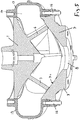
- einen perspektivisch dargestellten axialen Schnitt durch eine Kreiselpumpe,
- Fig. 2
- eine Ansicht des Pumpenlaufrades,
- Fig. 3
- eine Ansicht der Pumpenbodenplatte,
- Fig. 4
- einen Querschnitt durch eine Nut in der Bodenplatte,
- Fig. 5
- einen axialen Schnitt durch eine Kreiselpumpe mit außen verstellbarer Bodenplatte,
- Fig. 6
- einen axialen Schnitt durch eine Kreiselpumpe mit innerer beweglicher Lagerung der Bodenplatte gegen Federdruck,
- Fig. 7
- einen perspektivisch dargestellten, axialen Schnitt durch eine Kreiselpumpe mit beweglicher Lagerung eines segmentförmigen Bereichs der Bodenplatte,
- Fig. 8
- eine perspektivische Ansicht der Bodenplatte mit beweglichem Bereich/Segment.
- Die erfindungsgemäße Kreiselpumpe ist besonders zum Fördern von Abwasser und Schmutzwasser geeignet, das Feststoffteile enthält. Vorzugsweise ist sie Teil einer Tauchwasserpumpe.
- Das Pumpenlaufrad 1 ist von der Welle eines nicht dargestellten Elektromotors angetrieben und sitzt in einer Pumpenkammer, die zwischen einer die koaxiale Saugöffnung 8 bildenden Bodenplatte 7 und einer Trennwand liegt, die den Elektromotor von der Pumpenkammer trennt. Das Laufrad 1 aus Kunststoff oder Metall saugt über die Saugöffnung 8 das Fördermedium an und fördert es radial zum spiralförmigen Kanal 14, der von dem Pumpengehäuse 13 gebildet wird, das Laufrad umgibt und in den Pumpendruckstutzen mündet. Die Bodenplatte 7 ist auf ihrer dem Laufrad 1 zugewandten Seite muldenförmig insbesondere konkav gewölbt und die Höhe der Schaufeln 3, 4 nimmt entsprechend der Bodenplattenwölbung nach außen hin ab.
- Das Laufrad 1 ist ein halb offenes Laufrad, d. h. es weist auf der der Trennwand 13 zugewandten Seite eine kreisrunde Tragscheibe (Deckscheibe) 2 auf und besitzt keine vordere Deckscheibe. Auf der der Saugöffnung 8 zugewandten Fläche trägt die Tragscheibe zwei Schaufeln 3, 4, die (insbesondere C-förmig) gekrümmt sind, wobei die konkave Fläche jeder Schaufel 3, 4 der Laufradachse zugewandt ist. Statt zweier Schaufeln können auch eine, drei oder mehr Schaufeln an der Tragscheibe 2 befestigt insbesondere angeformt sein.
- Die etwa C-förmig gekrümmten Schaufeln 3, 4 erstrecken sich von innen nach außen bis zum Rand des Laufrads 1, wobei die Erzeugende der Schaufel sich parallel oder schräg zur Pumpenachse und damit zur Laufradachse erstreckt, so dass jede Schaufel senkrecht oder schräg zur planen Rückfläche 2a der Tragscheibe 2 auf der sich zur Scheibenmitte ansteigenden Tragscheibenvorderseite 2b steht. Die freie Vorderkante jeder Schaufel 3, 4 bildet eine längliche Verdickung 12, die im Ausführungsbeispiel nach
Fig. 1 als Profil sich entlang der Vorderkante erstreckt, wobei das Profil einen drei-, vier-oder mehreckigen Querschnitt besitzt mit einer der inneren Oberfläche 7c der Bodenplatte 7 zugewandten schrägen Längsfläche, die als Fase 6 parallel zur Oberfläche 7c verläuft. Hierbei beträgt der Abstand zwischen der Längsfläche/Fase 6 und der Oberfläche 7ca vorzugsweise 0,5 bis 2 mm. Auch kann hierbei der Abstand zwischen den Schaufeln 3, 4 und der Bodenplatte 7 von der Schaufeleintrittskante bis zur Schaufelaustrittskante zunehmen. - In nicht dargestellten Ausführungen ist die längliche Verdickung 12 nicht von einem Profil mit einem über die Länge gleichbleibendem Querschnitt gebildet, sondern die Verdickung 12 ist entweder nur teilweise insbesondere abschnittsweise profilförmig oder sein Querschnitt nimmt von einem zum anderen Ende in seiner Größe kontinuierlich zu oder ab. In allen Ausführungen ist der größte Querschnitt der länglichen Verdickung 12 stets größer als die Breite bzw. Dicke D der Schaufel 3, 4. Hierbei steht die Verdickung 12 auf beiden oder zumindest auf einer Seite der Schaufel vor.
- Das in
Fig. 2 dargestellte innere Ende 9a jeder Schaufel 3, 4, das die Eintrittskante der Schaufel bildet, trägt eine längliche insbesondere angeformte Verdickung 9, die entlang dem inneren Schaufelende 9a verläuft und im inFig. 2 gezeigtem Ausführungsbeispiel parallel zur Laufradachse steht. Es kann aber auch zumindest eine der Verdickungen schräg und damit in einem spitzen Winkel zur Laufradachse angeordnet sein. - Im Ausführungsbeispiel sind beide Verdickungen 9 von Profilen mit kreisförmigem Querschnitt gebildet. Stattdessen können die Profile auch anders geformte Querschnitte aufweisen, insbesondere ovale oder elliptische. Ferner kann der Querschnitt sich über seine Länge insbesondere abschnittsweise in Form und/oder Größe verändern. In allen Ausführungen der länglichen Verdickungen 9 und 12 sind diese vorzugsweise aus dem Material der Schaufel und damit aus demselben Kunststoff oder Metall der Schaufel und vorzugsweise angeformt.
- Der Abstand zwischen der Bodenplatte 7 und den Schaufeln 3, 4 ist verstellbar, so dass die Pumpe an die verschiedenen Beimengungen im Abwasser oder Schmutzwasser anpassbar ist. Entweder ist die gesamte Bodenplatte in ihrer Höhe verstellbar oder zumindest der von den Schaufeln überfahrene Bereich. Das Verstellen erfolgt z. B. durch Gewinde, Schrauben 16 oder Keilflächen von Hand insbesondere mit Werkzeugen oder aber motorisch, hydraulisch oder pneumatisch insbesondere rechnergesteuert und/oder ferngesteuert.
- In der Ausführung nach
Fig. 5 ist die Bodenplatte 7 an dem Pumpengehäuse 13 durch Stellschrauben 16 befestigt, die am äußeren Rand der Bodenplatte angeordnet sind, so dass ein Verstellen des Abstandes der Bodenplatte 7 von dem Laufrad 1 von außen erfolgen kann. - In der Ausführung nach
Fig. 6 liegt die Bodenplatte 7 innerhalb des Pumpengehäuses 13, so dass sie von der Gehäusewand 13a außen überdeckt ist. Hierbei besitzt die Bodenplatte 7 eine mittige Öffnung 7d, die mit der Saugöffnung 8 der Gehäusewand fluchtet. - Die innere Bodenplatte 7 ist durch mindestens eine, vorzugsweise drei oder vier Schrauben 16 an der Gehäusewand gelagert, die die Saugöffnung 8 umgibt. Hierbei liegt jede Schraube 16 in einer Bohrung 17 der Bodenplatte 7 ein. Die Bohrung 17 besitzt eine Erweiterung 18, die sich zum Laufrad hin öffnet und in der der Schraubenkopf 21 einliegt. Eine zur Bodenplatte hin sich öffnende Erweiterung 19 besitzt auch die Gewindebohrung in der Gehäusewand, wobei in dieser Erweiterung 19 eine Schraubendruckfeder 20 einliegt, die an der Unterseite der Bodenplatte 7 anliegt, um die Bodenplatte in Richtung des Laufrades 1 zu drücken. Da zwischen der Unterseite der Bodenplatte 7 und der Innenseite der Gehäusewand ein Abstand von mehreren Millimetern besteht, kann die Bodenplatte nach unten (in
Fig. 6 ) ausweichen, wenn ein größeres Feststoffteil zwischen die Bodenplatte und die äußeren Schaufelkanten des Laufrades gelangt. - Die Ausführung nach
Fig. 7 unterscheidet sich von der nachFig. 6 dadurch, dass die innen gelagerte Bodenplatte einen am Pumpengehäuse unbeweglich oder beweglich gelagerten ersten Bereich 7a aufweist, auf dem ein zweiter insbesondere segmentförmiger Bereich 7b gegen Federdruck beweglich gelagert ist und/oder durch elastische Verformbarkeit des Bauteils beweglich gehalten ist. Bei dieser Ausführung liegt der Kopf 21 der Schraube(n) in einer Bohrungserweiterung 18 des zweiten plattenförmigen, insbesondere segmentförmigen Bereichs 7b, so dass zumindest der zweite Bereich bzw. das Segment 7b sich von dem Laufrad 1 entfernend gegen den Druck der Feder 20 ausweichen kann und/oder sich verformt, wenn größere Feststoffteile zwischen Laufradschaufeln und das plattenförmige Segment 7b gelangen. - Die Bodenplatte 7 weist, wie in
Fig. 3 dargestellt, drei insbesondere C-förmig gekrümmte Nuten 10 auf, die von der Saugöffnung 8 ausgehen und sich bis zum Außenrand der Bodenplatte 7 erstrecken und entgegengesetzt der Krümmung der Schaufeln 3, 4 gekrümmt sind. Die Nuten 10 unterstützen das Fördern der Feststoffe radial nach außen, so dass ein Selbstreinigungseffekt eintritt. Das Fördern nach außen wird noch dadurch verstärkt, dass von den zwei Seitenwänden der Nuten 10, diejenige Seitenwand, die von einer Schaufel 3, 4 zuletzt überfahren wird, eine Schrägfläche 15 bildet, die die Nut nach außen hin erweitert (sieheFig. 4 ). Die Schrägfläche 15 bildet mit der Oberfläche der Bodenplatte 7 einen Winkel α von 110 bis 160 Grad. - Statt drei Nuten können in der Bodenplatte auch eine, zwei, vier oder mehr Nuten eingebracht sein.
- Die vorzugsweise zylindrische Saugöffnung 8 weist in ihrer Innenwand nutenförmige Strömungskanäle 11 auf, die vorzugsweise parallel zur Haupt-Strömungsrichtung in der Saugöffnung angeordnet sind, so dass die Feststoffe im Abwasser bzw. Schmutzwasser zum Laufrad abweisend geführt werden und die Gefahr einer Verstopfung reduziert wird. Hierbei sind die nutenförmigen Strömungskanäle 11 in gleichen Winkelabständen über die Innenwand der Saugöffnung verteilt. Im Ausführungsbeispiel nach
Fig. 3 sind sechs Strömungskanäle 11 dargestellt. Die Anzahl kann aber auch kleiner (3 bis 5) oder auch größer (7 bis 12) sein.
Claims (11)
- Kreiselpumpe, insbesondere Abwasser-Tauchmotorpumpe, mit einem Laufrad (1), dessen der Pumpensaugöffnung zugewandte Stirnseite offen ist und nur die der Saugöffnung (8) abgewandte Laufrad-Stirnseite durch eine kreisförmige koaxiale Laufrad-Tragscheibe (2) bedeckt ist, an der gekrümmte Laufradschaufeln (3, 4) befestigt insbesondere angeformt sind, dadurch gekennzeichnet, dass eine die Saugöffnung (8) aufweisende, dem Laufrad (1) zugewandte Bodenplatte (7) einen am Pumpengehäuse (13) unbeweglich oder beweglich gelagerten ersten Bereich (7a) und mindestens einen am ersten Bereich (7a) und/oder an der Gehäusewand gegen Federdruck beweglich gelagerten und/oder verformbaren zweiten, plattenförmigen Bereich (7b) in Form eines Segments (7b) derart aufweist, dass sich ihr Abstand oder zumindest der Abstand des Segments (7b) oder der Segmente (7b) zum Laufrad (1) und damit zu den Laufradschaufeln (3, 4) ändern kann, wobei der bewegliche zweite Bereich (7b) durch mindestens eine Schraube (16) begrenzt beweglich am unbeweglichen ersten Bereich (7a) und/oder an der Gehäusewand gehalten ist.
- Kreiselpumpe nach Anspruch 1, dadurch gekennzeichnet, dass die Bodenplatte (7) beweglich verstellbar und/oder verformbar ist.
- Kreiselpumpe nach Anspruch 1 oder 2, dadurch gekennzeichnet, dass die Bodenplatte (7) oder das/die Segment(e) (7a) der Bodenplatte durch mindestens eine Stellschraube (16) an dem Pumpengehäuse (13) gelagert ist/sind.
- Kreiselpumpe nach Anspruch 3, dadurch gekennzeichnet, dass die in das Pumpengehäuse eingeschraubte(n) Stellschraube(n) (16) die Bodenplatte (7) durchdringt/durchdringen und mit ihrem Kopf (21) in einer Bohrungserweiterung (18) einliegt/einliegen, die sich zum Laufrad (1) hin öffnet.
- Kreiselpumpe nach Anspruch 3 oder 4, dadurch gekennzeichnet, dass die Stellschraube(n) (16) von einer Schraubendruckfeder (20) umgeben ist, die den Federdruck auf die Bodenplatte (7) erzeugt.
- Kreiselpumpe nach einem der vorherigen Ansprüche, dadurch gekennzeichnet, dass der Abstand zwischen den Schaufeln (3, 4) und der Bodenplatte (7, 7c) 0,5 bis 2 mm beträgt.
- Kreiselpumpe nach einem der vorherigen Ansprüche, dadurch gekennzeichnet, dass die Bodenplatte (7) auf ihrer dem Laufrad zugewandten Seite muldenförmig insbesondere konkav gewölbt ist und die Höhe der Schaufeln (3, 4) entsprechend der Bodenplattenwölbung nach außen hin abnimmt.
- Kreiselpumpe nach einem der vorherigen Ansprüche, dadurch gekennzeichnet, dass die Saugöffnung (8) in ihrer Innenwand nutenförmige Strömungskanäle (11) aufweist, die vorzugsweise parallel zur Haupt-Strömungsrichtung in der Saugöffnung angeordnet sind.
- Kreiselpumpe nach Anspruch 8, dadurch gekennzeichnet, dass die Innenwand der Saugöffnung (8) zylindrisch ist und die Strömungskanäle (11) achsparallel zur Achse der Zylinderinnenwand angeordnet sind.
- Kreiselpumpe nach einem der vorherigen Ansprüche, dadurch gekennzeichnet,- dass die die Saugöffnung (8) aufweisende Bodenplatte (7) des Pumpengehäuses, über die die freien Kanten (3a, 4a) der Schaufeln (3, 4) in geringem Abstand hinwegstreichen, mindestens eine, vorzugsweise zwei, drei oder mehr insbesondere C-förmig gekrümmte Nuten (10) aufweist,- dass die Nuten (10) von der Saugöffnung (8) ausgehen und sich bis zum Außenrand der Bodenplatte (7) erstrecken, und- dass die Nuten (10) entgegengesetzt der Krümmung der Schaufeln (3, 4) gekrümmt sind.
- Kreiselpumpe nach Anspruch 10, dadurch gekennzeichnet, dass von den zwei Seitenwänden der Nuten (10), diejenige Seitenwand, die von einer Schaufel (3, 4) zuletzt überfahren wird, eine Schrägfläche (15) bildet, die die Nut nach außen hin erweitert.
Applications Claiming Priority (2)
| Application Number | Priority Date | Filing Date | Title |
|---|---|---|---|
| DE102012023734.0A DE102012023734A1 (de) | 2012-12-05 | 2012-12-05 | Kreiselpumpe insbesondere für Abwasser oder Schmutzwasser |
| PCT/EP2013/003626 WO2014086472A1 (de) | 2012-12-05 | 2013-12-02 | Kreiselpumpe insbesondere für abwasser oder schmutzwasser |
Publications (2)
| Publication Number | Publication Date |
|---|---|
| EP2929191A1 EP2929191A1 (de) | 2015-10-14 |
| EP2929191B1 true EP2929191B1 (de) | 2020-07-15 |
Family
ID=49766025
Family Applications (1)
| Application Number | Title | Priority Date | Filing Date |
|---|---|---|---|
| EP13805772.4A Active EP2929191B1 (de) | 2012-12-05 | 2013-12-02 | Kreiselpumpe insbesondere für abwasser oder schmutzwasser |
Country Status (5)
| Country | Link |
|---|---|
| US (1) | US9869326B2 (de) |
| EP (1) | EP2929191B1 (de) |
| CN (1) | CN104903584B (de) |
| DE (1) | DE102012023734A1 (de) |
| WO (1) | WO2014086472A1 (de) |
Families Citing this family (28)
| Publication number | Priority date | Publication date | Assignee | Title |
|---|---|---|---|---|
| JP6415116B2 (ja) | 2014-05-30 | 2018-10-31 | 株式会社荏原製作所 | 汚水ポンプ用のケーシングライナ及びこれを備えた汚水ポンプ |
| EP3034887B1 (de) | 2014-12-15 | 2019-08-07 | Sulzer Management AG | Positionierung einer deckscheibe einer pumpe mit hilfe von schraubenkopf-markierungen |
| US10837456B2 (en) * | 2015-03-27 | 2020-11-17 | Ebara Corporation | Volute pump |
| JP6488167B2 (ja) * | 2015-03-27 | 2019-03-20 | 株式会社荏原製作所 | 渦巻ポンプ |
| EP3171029B1 (de) * | 2015-11-17 | 2019-10-16 | Cornell Pump Company | Pumpe mit vorderen umlenkschaufeln, verschleissplatte und laufrad mit auspumpschaufeln |
| US10731651B2 (en) * | 2016-02-23 | 2020-08-04 | Baker Hughes, A Ge Company, Llc | Apertures spaced around impeller bottom shroud of centrifugal pump |
| DE102016225908A1 (de) | 2016-12-21 | 2018-06-21 | KSB SE & Co. KGaA | Freistrompumpe |
| PE20211153A1 (es) | 2017-10-12 | 2021-06-28 | Weir Minerals Australia Ltd | Componente de entrada para una bomba de lechada |
| CN108443164A (zh) * | 2018-04-23 | 2018-08-24 | 汉能(天津)工业泵有限公司 | 轻型大流量低液面抽排泵 |
| CN108302047A (zh) * | 2018-04-23 | 2018-07-20 | 汉能(天津)工业泵有限公司 | 一种耐磨防卡死泵腔结构 |
| CN108457904A (zh) * | 2018-04-23 | 2018-08-28 | 汉能(天津)工业泵有限公司 | 一种可调节式吸入口 |
| LU100831B1 (de) * | 2018-06-12 | 2019-12-12 | Wilo Se | Kreiselpumpe mit einem Pumpengehäuse |
| US11339804B2 (en) * | 2018-08-01 | 2022-05-24 | Liberty Pumps, Inc. | Self-cleaning pump |
| EP4394188A3 (de) * | 2018-12-21 | 2024-09-11 | Grundfos Holding A/S | Kreiselpumpe |
| US11230979B2 (en) | 2019-03-08 | 2022-01-25 | Pratt & Whitney Canada Corp. | Aircraft engine fuel system and method |
| US11459958B2 (en) | 2019-03-22 | 2022-10-04 | Pratt & Whitney Canada Corp. | Rotodynamic pump having a body defining a body cavity with a first and second housing portion defining a portion of an impeller cavity and disposed within the body cavity wherein the body cavity extends at least in part around the second housing portion and the housing portions defining an impeller clearance |
| US11280342B2 (en) | 2019-04-05 | 2022-03-22 | Pratt & Whitney Canada Corp. | Rotodynamic pump and method |
| DE102019124590A1 (de) * | 2019-09-12 | 2021-03-18 | HWC GmbH & Co. KG | Kreiselpumpe und Verfahren zum Einstellen eines Axialspalts |
| CN110966208A (zh) * | 2019-11-26 | 2020-04-07 | 烟台龙港泵业股份有限公司 | 一种用于pvc浆料s型回旋式叶片的离心泵 |
| CN112539181B (zh) * | 2020-11-30 | 2024-06-25 | 镇江福泰克流体技术有限公司 | 一种高扬程的立式输卤泵 |
| CN112502998B (zh) * | 2020-12-01 | 2022-08-05 | 石家庄栾兴泵业有限公司 | 一种低噪节能的双壳渣浆泵 |
| CN113819088B (zh) * | 2021-09-07 | 2023-08-08 | 安徽凯特泵业有限公司 | 一种具有角度调节功能的潜水排污泵 |
| CN115788919A (zh) | 2021-09-09 | 2023-03-14 | 创科无线普通合伙 | 潜水泵 |
| CN115450922A (zh) * | 2022-07-25 | 2022-12-09 | 毅飞泵业(福州)有限公司 | 一种半开式叶轮水泵及其制作方法 |
| IT202200026577A1 (it) * | 2022-12-22 | 2024-06-22 | Caprari Spa | Pompa centrifuga |
| IT202200026505A1 (it) * | 2022-12-22 | 2024-06-22 | Caprari Spa | Pompa centrifuga |
| CN117514937B (zh) * | 2024-01-05 | 2024-03-12 | 东营合瑞石油技术有限责任公司 | 一种防堵塞泥浆泵 |
| CN120576125B (zh) * | 2025-07-15 | 2026-03-13 | 沈阳东野泵业有限公司 | 一种节能高效离心式水泵 |
Family Cites Families (20)
| Publication number | Priority date | Publication date | Assignee | Title |
|---|---|---|---|---|
| DE7212196U (de) * | Grundfos As | |||
| CH476213A (de) * | 1966-06-08 | 1969-07-31 | Luwa Ag | Radialventilator für pneumatische Förderanlage |
| FR2681906B1 (fr) * | 1991-09-27 | 1995-01-20 | Renault Vehicules Ind | Pompe centrifuge pour circuit de liquide de refroidissement de moteur a combustion. |
| DE4142120A1 (de) * | 1991-12-20 | 1993-06-24 | Porsche Ag | Kuehlwasserpumpe fuer eine brennkraftmaschine |
| JP3468529B2 (ja) * | 1996-03-06 | 2003-11-17 | 株式会社日立製作所 | プロペラファン |
| SE520417C2 (sv) * | 1997-12-18 | 2003-07-08 | Flygt Ab Itt | Pump av centrifugal- eller halvaxiell typ avsedd för pumpning av orensat avloppsvatten |
| DE19823603A1 (de) | 1998-05-27 | 1999-12-02 | Behr Thermot Tronik Gmbh & Co | Vorrichtung zum Steuern der Kühlmitteltemperatur eines Verbrennungsmotors eines Fahrzeuges |
| GB9814040D0 (en) | 1998-06-29 | 1998-08-26 | Martin William | Sonic device |
| US6390768B1 (en) * | 1999-03-22 | 2002-05-21 | David Muhs | Pump impeller and related components |
| AUPR564501A0 (en) * | 2001-06-13 | 2001-07-12 | Warman International Limited | Apparatus for use in pumps |
| ITBO20020142A1 (it) * | 2002-03-22 | 2003-09-22 | Pierburg Spa | Pompo acqua autoregolante |
| EP1538339B1 (de) * | 2003-12-04 | 2006-11-22 | TCG Unitech Systemtechnik GmbH | Radialpumpe |
| EP1538338B1 (de) | 2003-12-04 | 2006-06-14 | TCG Unitech Systemtechnik GmbH | Radialpumpe |
| DE102005056200A1 (de) * | 2005-11-25 | 2007-06-06 | Audi Ag | Pumpe für ein flüssiges Medium, insbesondere Kühlmittelpumpe, sowie Stellelement für eine solche Pumpe |
| CN2874088Y (zh) * | 2005-12-20 | 2007-02-28 | 上海连成(集团)有限公司 | 一种开式叶轮间隙可调节装置 |
| EP1906025A1 (de) | 2006-09-22 | 2008-04-02 | Frideco AG | Zentrifugalradpumpe |
| SE531147C2 (sv) | 2007-05-15 | 2009-01-07 | Itt Mfg Enterprises Inc | Dränkbar centrifugalpump med normal- och uttömningsdrifttillstånd |
| CN201401341Y (zh) * | 2009-04-28 | 2010-02-10 | 华南理工大学 | 一种工艺流程浆泵 |
| DE102010026176B4 (de) * | 2010-07-06 | 2015-12-17 | Iav Gmbh Ingenieurgesellschaft Auto Und Verkehr | Vorrichtung und Verfahren zur Kennfeldstabilisierung eines Verdichters |
| CN102374172A (zh) * | 2010-08-12 | 2012-03-14 | 江苏尚宝罗泵业有限公司 | 一种叶轮可调整的无堵塞旋转式纸浆泵 |
-
2012
- 2012-12-05 DE DE102012023734.0A patent/DE102012023734A1/de not_active Withdrawn
-
2013
- 2013-12-02 WO PCT/EP2013/003626 patent/WO2014086472A1/de not_active Ceased
- 2013-12-02 EP EP13805772.4A patent/EP2929191B1/de active Active
- 2013-12-02 US US14/646,305 patent/US9869326B2/en not_active Expired - Fee Related
- 2013-12-02 CN CN201380069643.5A patent/CN104903584B/zh active Active
Non-Patent Citations (1)
| Title |
|---|
| None * |
Also Published As
| Publication number | Publication date |
|---|---|
| CN104903584B (zh) | 2017-07-14 |
| US20150292519A1 (en) | 2015-10-15 |
| WO2014086472A1 (de) | 2014-06-12 |
| DE102012023734A1 (de) | 2014-06-05 |
| CN104903584A (zh) | 2015-09-09 |
| EP2929191A1 (de) | 2015-10-14 |
| US9869326B2 (en) | 2018-01-16 |
Similar Documents
| Publication | Publication Date | Title |
|---|---|---|
| EP2929191B1 (de) | Kreiselpumpe insbesondere für abwasser oder schmutzwasser | |
| DE102009056010B4 (de) | Flügelzellenpumpe | |
| EP2188532B1 (de) | Pumpenlaufrad und pumpe umfassend ein derartiges pumpenlaufrad | |
| EP3779201B1 (de) | Abstreifelement für laufradeintrittskanten von abwasserpumpen | |
| EP1906026B1 (de) | Zentrifugalradpumpe | |
| EP2643595B1 (de) | Selbstreinigende schraubenzentrifugalradpumpe mit rezirkulation hinter dem schaufelrad | |
| EP4065845B1 (de) | Pumpenverschluss | |
| DE102008057849A1 (de) | Schneidvorrichtung einer Pumpe | |
| EP1296062B1 (de) | Kreiselpumpe | |
| EP2497956A1 (de) | Freistrompumpe | |
| DE102012023731B4 (de) | Kreiselpumpe insbesondere für Abwasser oder Schmutzwasser | |
| EP3581803B1 (de) | Kreiselpumpe mit regelung des spaltes zwischen deckel und laufrad | |
| EP1300594B1 (de) | Abwasserkreiselpumpe | |
| EP2616640B1 (de) | Drehkolbenpumpe und drehkolben | |
| EP1187991B1 (de) | Förderpumpe | |
| EP3853480B1 (de) | Pumpenanordnung | |
| EP1766238B1 (de) | Einflügelvakuumpumpe | |
| DE102015212653B4 (de) | Haushaltsgerät | |
| EP2535590A2 (de) | Kreiselpumpe mit integriertem Schneidwerk | |
| DE60311165T2 (de) | Kreiselpumpe für niedrige Flussraten mit verbesserter Ansaughöhe | |
| EP4108934A1 (de) | Anordnung umfassend ein laufrad und einen schneidkopf für mit feststoff belastete flüssigkeit einer pumpe | |
| DE3108507C2 (de) | ||
| WO2012022595A2 (de) | Flügelzellenpumpe | |
| EP2100041B1 (de) | Motorkreiselpumpe | |
| DE239731C (de) |
Legal Events
| Date | Code | Title | Description |
|---|---|---|---|
| PUAI | Public reference made under article 153(3) epc to a published international application that has entered the european phase |
Free format text: ORIGINAL CODE: 0009012 |
|
| 17P | Request for examination filed |
Effective date: 20150603 |
|
| AK | Designated contracting states |
Kind code of ref document: A1 Designated state(s): AL AT BE BG CH CY CZ DE DK EE ES FI FR GB GR HR HU IE IS IT LI LT LU LV MC MK MT NL NO PL PT RO RS SE SI SK SM TR |
|
| AX | Request for extension of the european patent |
Extension state: BA ME |
|
| DAX | Request for extension of the european patent (deleted) | ||
| STAA | Information on the status of an ep patent application or granted ep patent |
Free format text: STATUS: EXAMINATION IS IN PROGRESS |
|
| 17Q | First examination report despatched |
Effective date: 20181207 |
|
| GRAP | Despatch of communication of intention to grant a patent |
Free format text: ORIGINAL CODE: EPIDOSNIGR1 |
|
| STAA | Information on the status of an ep patent application or granted ep patent |
Free format text: STATUS: GRANT OF PATENT IS INTENDED |
|
| INTG | Intention to grant announced |
Effective date: 20200302 |
|
| GRAS | Grant fee paid |
Free format text: ORIGINAL CODE: EPIDOSNIGR3 |
|
| GRAA | (expected) grant |
Free format text: ORIGINAL CODE: 0009210 |
|
| STAA | Information on the status of an ep patent application or granted ep patent |
Free format text: STATUS: THE PATENT HAS BEEN GRANTED |
|
| AK | Designated contracting states |
Kind code of ref document: B1 Designated state(s): AL AT BE BG CH CY CZ DE DK EE ES FI FR GB GR HR HU IE IS IT LI LT LU LV MC MK MT NL NO PL PT RO RS SE SI SK SM TR |
|
| REG | Reference to a national code |
Ref country code: GB Ref legal event code: FG4D Free format text: NOT ENGLISH Ref country code: CH Ref legal event code: EP |
|
| REG | Reference to a national code |
Ref country code: IE Ref legal event code: FG4D Free format text: LANGUAGE OF EP DOCUMENT: GERMAN |
|
| REG | Reference to a national code |
Ref country code: DE Ref legal event code: R096 Ref document number: 502013014928 Country of ref document: DE |
|
| REG | Reference to a national code |
Ref country code: AT Ref legal event code: REF Ref document number: 1291328 Country of ref document: AT Kind code of ref document: T Effective date: 20200815 |
|
| REG | Reference to a national code |
Ref country code: LT Ref legal event code: MG4D |
|
| REG | Reference to a national code |
Ref country code: NL Ref legal event code: MP Effective date: 20200715 |
|
| PG25 | Lapsed in a contracting state [announced via postgrant information from national office to epo] |
Ref country code: NO Free format text: LAPSE BECAUSE OF FAILURE TO SUBMIT A TRANSLATION OF THE DESCRIPTION OR TO PAY THE FEE WITHIN THE PRESCRIBED TIME-LIMIT Effective date: 20201015 Ref country code: LT Free format text: LAPSE BECAUSE OF FAILURE TO SUBMIT A TRANSLATION OF THE DESCRIPTION OR TO PAY THE FEE WITHIN THE PRESCRIBED TIME-LIMIT Effective date: 20200715 Ref country code: PT Free format text: LAPSE BECAUSE OF FAILURE TO SUBMIT A TRANSLATION OF THE DESCRIPTION OR TO PAY THE FEE WITHIN THE PRESCRIBED TIME-LIMIT Effective date: 20201116 Ref country code: ES Free format text: LAPSE BECAUSE OF FAILURE TO SUBMIT A TRANSLATION OF THE DESCRIPTION OR TO PAY THE FEE WITHIN THE PRESCRIBED TIME-LIMIT Effective date: 20200715 Ref country code: GR Free format text: LAPSE BECAUSE OF FAILURE TO SUBMIT A TRANSLATION OF THE DESCRIPTION OR TO PAY THE FEE WITHIN THE PRESCRIBED TIME-LIMIT Effective date: 20201016 Ref country code: SE Free format text: LAPSE BECAUSE OF FAILURE TO SUBMIT A TRANSLATION OF THE DESCRIPTION OR TO PAY THE FEE WITHIN THE PRESCRIBED TIME-LIMIT Effective date: 20200715 Ref country code: BG Free format text: LAPSE BECAUSE OF FAILURE TO SUBMIT A TRANSLATION OF THE DESCRIPTION OR TO PAY THE FEE WITHIN THE PRESCRIBED TIME-LIMIT Effective date: 20201015 Ref country code: HR Free format text: LAPSE BECAUSE OF FAILURE TO SUBMIT A TRANSLATION OF THE DESCRIPTION OR TO PAY THE FEE WITHIN THE PRESCRIBED TIME-LIMIT Effective date: 20200715 Ref country code: FI Free format text: LAPSE BECAUSE OF FAILURE TO SUBMIT A TRANSLATION OF THE DESCRIPTION OR TO PAY THE FEE WITHIN THE PRESCRIBED TIME-LIMIT Effective date: 20200715 |
|
| PG25 | Lapsed in a contracting state [announced via postgrant information from national office to epo] |
Ref country code: IS Free format text: LAPSE BECAUSE OF FAILURE TO SUBMIT A TRANSLATION OF THE DESCRIPTION OR TO PAY THE FEE WITHIN THE PRESCRIBED TIME-LIMIT Effective date: 20201115 Ref country code: LV Free format text: LAPSE BECAUSE OF FAILURE TO SUBMIT A TRANSLATION OF THE DESCRIPTION OR TO PAY THE FEE WITHIN THE PRESCRIBED TIME-LIMIT Effective date: 20200715 Ref country code: PL Free format text: LAPSE BECAUSE OF FAILURE TO SUBMIT A TRANSLATION OF THE DESCRIPTION OR TO PAY THE FEE WITHIN THE PRESCRIBED TIME-LIMIT Effective date: 20200715 Ref country code: RS Free format text: LAPSE BECAUSE OF FAILURE TO SUBMIT A TRANSLATION OF THE DESCRIPTION OR TO PAY THE FEE WITHIN THE PRESCRIBED TIME-LIMIT Effective date: 20200715 |
|
| PG25 | Lapsed in a contracting state [announced via postgrant information from national office to epo] |
Ref country code: NL Free format text: LAPSE BECAUSE OF FAILURE TO SUBMIT A TRANSLATION OF THE DESCRIPTION OR TO PAY THE FEE WITHIN THE PRESCRIBED TIME-LIMIT Effective date: 20200715 |
|
| REG | Reference to a national code |
Ref country code: DE Ref legal event code: R097 Ref document number: 502013014928 Country of ref document: DE |
|
| PG25 | Lapsed in a contracting state [announced via postgrant information from national office to epo] |
Ref country code: IT Free format text: LAPSE BECAUSE OF FAILURE TO SUBMIT A TRANSLATION OF THE DESCRIPTION OR TO PAY THE FEE WITHIN THE PRESCRIBED TIME-LIMIT Effective date: 20200715 Ref country code: EE Free format text: LAPSE BECAUSE OF FAILURE TO SUBMIT A TRANSLATION OF THE DESCRIPTION OR TO PAY THE FEE WITHIN THE PRESCRIBED TIME-LIMIT Effective date: 20200715 Ref country code: CZ Free format text: LAPSE BECAUSE OF FAILURE TO SUBMIT A TRANSLATION OF THE DESCRIPTION OR TO PAY THE FEE WITHIN THE PRESCRIBED TIME-LIMIT Effective date: 20200715 Ref country code: DK Free format text: LAPSE BECAUSE OF FAILURE TO SUBMIT A TRANSLATION OF THE DESCRIPTION OR TO PAY THE FEE WITHIN THE PRESCRIBED TIME-LIMIT Effective date: 20200715 Ref country code: SM Free format text: LAPSE BECAUSE OF FAILURE TO SUBMIT A TRANSLATION OF THE DESCRIPTION OR TO PAY THE FEE WITHIN THE PRESCRIBED TIME-LIMIT Effective date: 20200715 Ref country code: RO Free format text: LAPSE BECAUSE OF FAILURE TO SUBMIT A TRANSLATION OF THE DESCRIPTION OR TO PAY THE FEE WITHIN THE PRESCRIBED TIME-LIMIT Effective date: 20200715 |
|
| PLBE | No opposition filed within time limit |
Free format text: ORIGINAL CODE: 0009261 |
|
| STAA | Information on the status of an ep patent application or granted ep patent |
Free format text: STATUS: NO OPPOSITION FILED WITHIN TIME LIMIT |
|
| PG25 | Lapsed in a contracting state [announced via postgrant information from national office to epo] |
Ref country code: AL Free format text: LAPSE BECAUSE OF FAILURE TO SUBMIT A TRANSLATION OF THE DESCRIPTION OR TO PAY THE FEE WITHIN THE PRESCRIBED TIME-LIMIT Effective date: 20200715 |
|
| 26N | No opposition filed |
Effective date: 20210416 |
|
| PG25 | Lapsed in a contracting state [announced via postgrant information from national office to epo] |
Ref country code: SK Free format text: LAPSE BECAUSE OF FAILURE TO SUBMIT A TRANSLATION OF THE DESCRIPTION OR TO PAY THE FEE WITHIN THE PRESCRIBED TIME-LIMIT Effective date: 20200715 |
|
| REG | Reference to a national code |
Ref country code: CH Ref legal event code: PL |
|
| GBPC | Gb: european patent ceased through non-payment of renewal fee |
Effective date: 20201202 |
|
| PG25 | Lapsed in a contracting state [announced via postgrant information from national office to epo] |
Ref country code: SI Free format text: LAPSE BECAUSE OF FAILURE TO SUBMIT A TRANSLATION OF THE DESCRIPTION OR TO PAY THE FEE WITHIN THE PRESCRIBED TIME-LIMIT Effective date: 20200715 Ref country code: MC Free format text: LAPSE BECAUSE OF FAILURE TO SUBMIT A TRANSLATION OF THE DESCRIPTION OR TO PAY THE FEE WITHIN THE PRESCRIBED TIME-LIMIT Effective date: 20200715 |
|
| REG | Reference to a national code |
Ref country code: BE Ref legal event code: MM Effective date: 20201231 |
|
| PG25 | Lapsed in a contracting state [announced via postgrant information from national office to epo] |
Ref country code: IE Free format text: LAPSE BECAUSE OF NON-PAYMENT OF DUE FEES Effective date: 20201202 Ref country code: FR Free format text: LAPSE BECAUSE OF NON-PAYMENT OF DUE FEES Effective date: 20201231 Ref country code: LU Free format text: LAPSE BECAUSE OF NON-PAYMENT OF DUE FEES Effective date: 20201202 |
|
| PG25 | Lapsed in a contracting state [announced via postgrant information from national office to epo] |
Ref country code: GB Free format text: LAPSE BECAUSE OF NON-PAYMENT OF DUE FEES Effective date: 20201202 Ref country code: CH Free format text: LAPSE BECAUSE OF NON-PAYMENT OF DUE FEES Effective date: 20201231 Ref country code: LI Free format text: LAPSE BECAUSE OF NON-PAYMENT OF DUE FEES Effective date: 20201231 |
|
| REG | Reference to a national code |
Ref country code: AT Ref legal event code: MM01 Ref document number: 1291328 Country of ref document: AT Kind code of ref document: T Effective date: 20201202 |
|
| PG25 | Lapsed in a contracting state [announced via postgrant information from national office to epo] |
Ref country code: AT Free format text: LAPSE BECAUSE OF NON-PAYMENT OF DUE FEES Effective date: 20201202 |
|
| PG25 | Lapsed in a contracting state [announced via postgrant information from national office to epo] |
Ref country code: IS Free format text: LAPSE BECAUSE OF FAILURE TO SUBMIT A TRANSLATION OF THE DESCRIPTION OR TO PAY THE FEE WITHIN THE PRESCRIBED TIME-LIMIT Effective date: 20201115 Ref country code: TR Free format text: LAPSE BECAUSE OF FAILURE TO SUBMIT A TRANSLATION OF THE DESCRIPTION OR TO PAY THE FEE WITHIN THE PRESCRIBED TIME-LIMIT Effective date: 20200715 Ref country code: MT Free format text: LAPSE BECAUSE OF FAILURE TO SUBMIT A TRANSLATION OF THE DESCRIPTION OR TO PAY THE FEE WITHIN THE PRESCRIBED TIME-LIMIT Effective date: 20200715 Ref country code: CY Free format text: LAPSE BECAUSE OF FAILURE TO SUBMIT A TRANSLATION OF THE DESCRIPTION OR TO PAY THE FEE WITHIN THE PRESCRIBED TIME-LIMIT Effective date: 20200715 |
|
| PG25 | Lapsed in a contracting state [announced via postgrant information from national office to epo] |
Ref country code: MK Free format text: LAPSE BECAUSE OF FAILURE TO SUBMIT A TRANSLATION OF THE DESCRIPTION OR TO PAY THE FEE WITHIN THE PRESCRIBED TIME-LIMIT Effective date: 20200715 |
|
| PG25 | Lapsed in a contracting state [announced via postgrant information from national office to epo] |
Ref country code: BE Free format text: LAPSE BECAUSE OF NON-PAYMENT OF DUE FEES Effective date: 20201231 |
|
| P01 | Opt-out of the competence of the unified patent court (upc) registered |
Effective date: 20230615 |
|
| REG | Reference to a national code |
Ref country code: DE Ref legal event code: R084 Ref document number: 502013014928 Country of ref document: DE |
|
| PGFP | Annual fee paid to national office [announced via postgrant information from national office to epo] |
Ref country code: DE Payment date: 20251126 Year of fee payment: 13 |