EP2929598B1 - Dispositif de connexion - Google Patents
Dispositif de connexion Download PDFInfo
- Publication number
- EP2929598B1 EP2929598B1 EP13789714.6A EP13789714A EP2929598B1 EP 2929598 B1 EP2929598 B1 EP 2929598B1 EP 13789714 A EP13789714 A EP 13789714A EP 2929598 B1 EP2929598 B1 EP 2929598B1
- Authority
- EP
- European Patent Office
- Prior art keywords
- connection device
- housing
- components
- contact element
- contact elements
- Prior art date
- Legal status (The legal status is an assumption and is not a legal conclusion. Google has not performed a legal analysis and makes no representation as to the accuracy of the status listed.)
- Active
Links
Images


Classifications
-
- H—ELECTRICITY
- H01—ELECTRIC ELEMENTS
- H01R—ELECTRICALLY-CONDUCTIVE CONNECTIONS; STRUCTURAL ASSOCIATIONS OF A PLURALITY OF MUTUALLY-INSULATED ELECTRICAL CONNECTING ELEMENTS; COUPLING DEVICES; CURRENT COLLECTORS
- H01R13/00—Details of coupling devices of the kinds covered by groups H01R12/70 or H01R24/00 - H01R33/00
- H01R13/62—Means for facilitating engagement or disengagement of coupling parts or for holding them in engagement
- H01R13/629—Additional means for facilitating engagement or disengagement of coupling parts, e.g. aligning or guiding means, levers, gas pressure electrical locking indicators, manufacturing tolerances
- H01R13/631—Additional means for facilitating engagement or disengagement of coupling parts, e.g. aligning or guiding means, levers, gas pressure electrical locking indicators, manufacturing tolerances for engagement only
-
- H—ELECTRICITY
- H01—ELECTRIC ELEMENTS
- H01R—ELECTRICALLY-CONDUCTIVE CONNECTIONS; STRUCTURAL ASSOCIATIONS OF A PLURALITY OF MUTUALLY-INSULATED ELECTRICAL CONNECTING ELEMENTS; COUPLING DEVICES; CURRENT COLLECTORS
- H01R13/00—Details of coupling devices of the kinds covered by groups H01R12/70 or H01R24/00 - H01R33/00
- H01R13/648—Protective earth or shield arrangements on coupling devices, e.g. anti-static shielding
- H01R13/658—High frequency shielding arrangements, e.g. against EMI [Electro-Magnetic Interference] or EMP [Electro-Magnetic Pulse]
- H01R13/6581—Shield structure
-
- B—PERFORMING OPERATIONS; TRANSPORTING
- B60—VEHICLES IN GENERAL
- B60K—ARRANGEMENT OR MOUNTING OF PROPULSION UNITS OR OF TRANSMISSIONS IN VEHICLES; ARRANGEMENT OR MOUNTING OF PLURAL DIVERSE PRIME-MOVERS IN VEHICLES; AUXILIARY DRIVES FOR VEHICLES; INSTRUMENTATION OR DASHBOARDS FOR VEHICLES; ARRANGEMENTS IN CONNECTION WITH COOLING, AIR INTAKE, GAS EXHAUST OR FUEL SUPPLY OF PROPULSION UNITS IN VEHICLES
- B60K1/00—Arrangement or mounting of electrical propulsion units
-
- H—ELECTRICITY
- H01—ELECTRIC ELEMENTS
- H01R—ELECTRICALLY-CONDUCTIVE CONNECTIONS; STRUCTURAL ASSOCIATIONS OF A PLURALITY OF MUTUALLY-INSULATED ELECTRICAL CONNECTING ELEMENTS; COUPLING DEVICES; CURRENT COLLECTORS
- H01R13/00—Details of coupling devices of the kinds covered by groups H01R12/70 or H01R24/00 - H01R33/00
- H01R13/62—Means for facilitating engagement or disengagement of coupling parts or for holding them in engagement
- H01R13/629—Additional means for facilitating engagement or disengagement of coupling parts, e.g. aligning or guiding means, levers, gas pressure electrical locking indicators, manufacturing tolerances
- H01R13/631—Additional means for facilitating engagement or disengagement of coupling parts, e.g. aligning or guiding means, levers, gas pressure electrical locking indicators, manufacturing tolerances for engagement only
- H01R13/6315—Additional means for facilitating engagement or disengagement of coupling parts, e.g. aligning or guiding means, levers, gas pressure electrical locking indicators, manufacturing tolerances for engagement only allowing relative movement between coupling parts, e.g. floating connection
-
- H—ELECTRICITY
- H01—ELECTRIC ELEMENTS
- H01R—ELECTRICALLY-CONDUCTIVE CONNECTIONS; STRUCTURAL ASSOCIATIONS OF A PLURALITY OF MUTUALLY-INSULATED ELECTRICAL CONNECTING ELEMENTS; COUPLING DEVICES; CURRENT COLLECTORS
- H01R24/00—Two-part coupling devices, or either of their cooperating parts, characterised by their overall structure
- H01R24/38—Two-part coupling devices, or either of their cooperating parts, characterised by their overall structure having concentrically or coaxially arranged contacts
-
- H—ELECTRICITY
- H02—GENERATION; CONVERSION OR DISTRIBUTION OF ELECTRIC POWER
- H02K—DYNAMO-ELECTRIC MACHINES
- H02K11/00—Structural association of dynamo-electric machines with electric components or with devices for shielding, monitoring or protection
- H02K11/0094—Structural association with other electrical or electronic devices
-
- B—PERFORMING OPERATIONS; TRANSPORTING
- B60—VEHICLES IN GENERAL
- B60Y—INDEXING SCHEME RELATING TO ASPECTS CROSS-CUTTING VEHICLE TECHNOLOGY
- B60Y2400/00—Special features of vehicle units
- B60Y2400/61—Arrangements of controllers for electric machines, e.g. inverters
-
- H—ELECTRICITY
- H01—ELECTRIC ELEMENTS
- H01R—ELECTRICALLY-CONDUCTIVE CONNECTIONS; STRUCTURAL ASSOCIATIONS OF A PLURALITY OF MUTUALLY-INSULATED ELECTRICAL CONNECTING ELEMENTS; COUPLING DEVICES; CURRENT COLLECTORS
- H01R13/00—Details of coupling devices of the kinds covered by groups H01R12/70 or H01R24/00 - H01R33/00
- H01R13/46—Bases; Cases
- H01R13/502—Bases; Cases composed of different pieces
- H01R13/5025—Bases; Cases composed of different pieces one or more pieces being of resilient material
-
- H—ELECTRICITY
- H01—ELECTRIC ELEMENTS
- H01R—ELECTRICALLY-CONDUCTIVE CONNECTIONS; STRUCTURAL ASSOCIATIONS OF A PLURALITY OF MUTUALLY-INSULATED ELECTRICAL CONNECTING ELEMENTS; COUPLING DEVICES; CURRENT COLLECTORS
- H01R2105/00—Three poles
-
- H—ELECTRICITY
- H01—ELECTRIC ELEMENTS
- H01R—ELECTRICALLY-CONDUCTIVE CONNECTIONS; STRUCTURAL ASSOCIATIONS OF A PLURALITY OF MUTUALLY-INSULATED ELECTRICAL CONNECTING ELEMENTS; COUPLING DEVICES; CURRENT COLLECTORS
- H01R2201/00—Connectors or connections adapted for particular applications
- H01R2201/26—Connectors or connections adapted for particular applications for vehicles
Definitions
- the invention relates to a connecting device for the electrically conductive connection of electrical components, for example components of an electric drive unit of a motor vehicle.
- compact electric drive units which include at least one electric drive motor and a flanged directly to these gearbox and power electronics.
- a drive unit is for example from the DE 10 2009 040 896 A1 known.
- the power electronics in the immediate vicinity of the drive motor is arranged, but not directly fixed to this but rather on a cross member of the chassis of the motor vehicle.
- An electrical connection between the power electronics and the drive motor can then be done in a known manner via cable, the distance to be bridged by means of the cable because of the proximity of the drive motor and power electronics is very short.
- An advantage of the electrical connection of the power electronics and the drive motor by means of cables is that, owing to their flexibility, they can compensate for relative movements between these components which occur as a result of their independent fixing to the structure of the motor vehicle.
- a disadvantage of such a type of electrical connection is in particular the increased installation effort.
- a connecting device with the features of the preamble of claim 1 is known from US 2012/040553 A1 known.
- a housing part connecting the two receiving parts is designed as a bellows.
- the invention has the object, an advantageous possibility for electrical connection of spatially arranged to each other, possibly within limits relatively moving components, such as in particular a drive motor and power electronics in an electric drive unit for a motor vehicle, as they are from the DE 10 2009 040 896 A1 is known to indicate.
- the connecting device according to the invention By means of the connecting device according to the invention, electrical components arranged in proximity to one another can be electrically connected to one another, relative movements also being able to be absorbed without sliding contact points due to the flexibility of the conductors in connection with the corresponding configuration of the housing surrounding the conductor or conductors.
- the connecting device according to the invention is therefore not subject to increased relative wear due to increased wear and thus can ensure a secure electrical connection over a long period of time.
- the connecting device according to the invention is characterized by its ease of use as a unit of multiple transmission paths.
- the receiving parts are rigid, which may result in a stationary position of the contact elements, which may be advantageous for a secure contacting of the associated mating contact elements.
- the relative movement permitting property of the housing is achieved in that a housing part connecting the receiving parts is flexible. This can thus deform, whereby the relative movements of the electrically connected by the connecting device components can be accommodated.
- the flexibility of the housing part connecting the receiving parts results from a corresponding flexibility and elasticity of the material used for this housing part (also several materials).
- the housing part r according to the invention is formed of an elastomer (for example based on natural rubber or silicone rubber).
- an elastomer for example based on natural rubber or silicone rubber.
- structural measures for example integrated joints.
- connection means for example bores, latching or clamping pins, latching hooks, etc.
- connecting means for example bores, latching or clamping pins, latching hooks, etc.
- rigid design of the receiving parts can still improve the fixation of the connecting device to the components.
- a further preferred embodiment of the connecting device according to the invention can provide that the head (s) in an unloaded (ie in a not loaded by forces from the components) initial state of the housing arcuate (also multi-curved, eg S-shaped) in the housing / run , As a result, it can be ensured that the conductor (s) can also compensate for relative movements of the components which lead to an increased distance of the contact elements compared with the initial state from the conductor (s), without them (r) would have to be stretched.
- the conductor (s) is / are formed in the form of a ground strap or are formed by ground straps.
- These are flexible electrical conductors, in particular rectangular conductors or conductor bands, made of a wire mesh (for example made of copper wire).
- Such conductors are particularly suitable for the preferred use of the connecting device according to the invention for the transmission of high current (in particular currents that can reach or exceed 100 A) between the components, since they can have good flexibility despite Hochstromeignung.
- the housing forms a shield by the housing is at least partially formed electrically conductive.
- the housing may be e.g. be completely or partially made of metal.
- a metallic coating of the housing or at least a part thereof may be provided. It is preferably provided that a material of the housing comprises metallic particles, whereby the shielding effect is generated. This is particularly preferably implemented when the housing is at least partially formed from one or more elastomers, which may then comprise the metallic particles.
- the contact elements are designed in the form of plug contact elements which form plug connections with the mating plug contact elements. It may be particularly preferably provided that the plug-in contact elements of the connecting device according to the invention are formed pin-shaped, which are plugged into complementary socket-shaped mating plug contact elements of the components. This makes it possible, inter alia, to integrate the mating plug contact elements recessed into the components, whereby a contact protection for the potentially under high voltage mating plug contact elements can be achieved.
- An advantageous use of a connecting device according to the invention may be to electrically conductively connect at least two components in an electric (driving) drive unit for a motor vehicle. This is especially true if these components are arranged in spatial proximity to each other and / or are integrated into the motor vehicle, that during operation of the motor vehicle, a limited relative mobility between them may arise.
- power electronics may be connected by means of the connection device to a high-voltage electric drive motor (i.e., this is for electric drive of the motor vehicle).
- a high-voltage electric drive motor i.e., this is for electric drive of the motor vehicle.
- Such power electronics comprises at least one inverter, which converts a DC voltage, which is made available for example by a traction battery of the motor vehicle, into an AC voltage and in particular a three-phase AC voltage for the drive motor.
- high voltage is understood according to the invention an electrical voltage of at least 30 V at AC voltage and at least 60 V at DC.
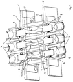
- the embodiment of a connecting device according to the invention shown in the drawings comprises two groups of three pin-shaped, metallic (plug) contact elements 1.
- the contact elements 1 of each group are immovably arranged in each case a receiving part 2 of a housing.
- the receiving parts 2 have corresponding passage openings through which the contact elements 1 extend.
- plug-in ends of the contact elements 1 protrude out of the housing, while their conductor-side ends project into the housing.
- a connection of the contact elements 1 with the receiving parts 2 can e.g. non-positively, positively and / or cohesively (for example by gluing) done.
- the receiving parts 2 having a rectangular shape are formed of a substantially rigid material (eg plastic) and have attachment openings 3 through which attachment means (eg latching or threaded bolts) can be inserted, around the connection device to the components, to the electrical connection of these is intended to fix.
- attachment means eg latching or threaded bolts
- the housing further comprises a housing part 4 connecting the receiving parts 2, which is formed from an elastomer and therefore has a comparatively high flexibility (in particular also elasticity). As a result, the two receiving parts 2 can move within limits in any direction relative to each other.
- Each two in the housing opposite contact elements 1 are connected by a conductor 5 in the form of a ground strap.
- a connection between the conductor-side ends of the contact elements 1 and the conductors 5 may be provided, for example by soldering.
- the design of the conductor 5 as earth straps despite their conditional by the relatively large cross-sections suitability for the transmission of high current, a comparatively high flexibility, so that they do not prevent a relative mobility of the receiving parts 2 to each other.
- the conductors are with an electrically insulating Coat surrounded.
- the conductors 5 are already in the initial state of the connecting device, i. in the form which assumes the housing due to the inherent stability in the unloaded state from outside, an arcuate course. This makes it possible that also relative movements of the two receiving parts 2, which lead to an increase in the distance between them, can be absorbed by the conductors 5, without having to be stretched. In the case of the housing, however, the receiving parts 2 connecting housing part 4 is stretched. In contrast, if a relative movement leads to a reduction of the distance between the receiving parts 2, this is compensated by the conductors 5 by a reduction of the radius of curvature of their curved course. The housing part 4 is compressed or otherwise deformed (bulged or kinked).
- a plurality of electrical particles are arranged distributed. These form a shield for the arranged inside the housing conductor 5 and thereby reduce the input and / or radiation of electrical or magnetic fields.
- the shielding effect is further improved by the fact that the housing part 4, in addition to a section surrounding the conductors 5, also comprises two partitions 10, which spatially separate the outer of the three conductors 5 from the middle conductor 5, respectively.
- FIG. 3 and 4 shows how two electrical components of a drive unit according to the invention for a motor vehicle are electrically connected by means of the connecting device.
- each of these connector parts comprises three, at their plug-side ends socket-shaped (counter) contact elements 7, in which the plug-side ends of the associated pin-shaped contact elements 1 of the connecting device are inserted.
- a radially expanded, annular coil spring 8 which is arranged in a circumferential groove in the plug-side end of the respective mating contact element 7, for a safe electrical contact.
- the conductor-side ends of the mating contact elements 7 each have a blind-hole-like opening for receiving and fixing (for example by soldering) a stripped end of a cable conductor (not shown).
- the mating contact elements 7 are fixed in a housing 9 of the respective connector part.
- the housings 9 of the connector parts are in turn secured to the housings 6 of the associated components.
- the flexible configuration of the conductors 5 and of the housing parts 4 connecting the housing part 4 allows a relative mobility of the two components to one another.
- the relative mobility between the components may be e.g. show that they are not attached to each other but are connected independently of each other to the structure of the motor vehicle.
- the components may be, for example, a power electronics and an electric drive motor for a motor vehicle.
- the power electronics provide the drive motor with electrical energy in the form of three-phase alternating current. Accordingly, the connection device also forms three transmission paths.
Landscapes
- Engineering & Computer Science (AREA)
- Chemical & Material Sciences (AREA)
- Combustion & Propulsion (AREA)
- Transportation (AREA)
- Mechanical Engineering (AREA)
- Power Engineering (AREA)
- Details Of Connecting Devices For Male And Female Coupling (AREA)
- Connector Housings Or Holding Contact Members (AREA)
Claims (11)
- Dispositif de connexion pour la connexion conductrice de l'électricité de composants électriques, comprenant- un premier élément de contact (1), qui est prévu pour un contact avec un élément de contact antagoniste correspondant (7) d'un premier des composants,- un second élément de contact (1), qui est prévu pour un contact avec un élément de contact antagoniste correspondant (7) d'un second des composants,- un conducteur flexible (5) qui connecte le premier élément de contact (1) avec le second élément de contact (1) de manière à conduire l'électricité, et- un boîtier, qui entoure le conducteur (5) et qui reçoit le premier élément de contact (1) dans une première partie de réception (2) et qui reçoit le second élément de contact (1) dans une seconde partie de réception (2), dans lequel le boîtier est réalisé de telle manière que celui-ci permet un mouvement relatif entre la première partie de réception (2) et la seconde partie de réception (2), caractérisé en ce qu'une partie de boîtier (4) qui connecte les parties de réception (2) est réalisée en élastomère et est flexible.
- Dispositif de connexion selon la revendication 1, caractérisé en ce que les parties de réception (2) sont réalisées rigides.
- Dispositif de connexion selon l'une des revendications précédentes, caractérisé en ce que les parties de réception (2) comprennent des moyens de liaison pour la fixation du dispositif de connexion sur les composants.
- Dispositif de connexion selon l'une des revendications précédentes, caractérisé en ce que le conducteur (5) s'étend, dans un état de départ non chargé du boîtier, en formant un arc dans le boîtier.
- Dispositif de connexion selon l'une des revendications précédentes, caractérisé en ce que le conducteur (5) est réalisé sous la forme d'un ruban de masse.
- Dispositif de connexion selon l'une des revendications précédentes, caractérisé en ce que le boîtier forme un blindage.
- Dispositif de connexion selon la revendication 6, caractérisé en ce qu'un matériau du boîtier inclut des particules métalliques.
- Dispositif de connexion selon l'une des revendications précédentes, caractérisé en ce que l'élastomère inclut des particules métalliques.
- Dispositif de connexion selon l'une des revendications précédentes, caractérisé en ce que les éléments de contact (1) sont réalisés sous la forme d'éléments de contact à enfichage.
- Unité d'entraînement électrique pour un véhicule automobile comprenant au moins deux composants, connectés de manière à conduire l'électricité au moyen d'un dispositif de connexion selon l'une des revendications précédentes.
- Unité d'entraînement électrique selon la revendication 10, caractérisée en ce qu'une électronique de puissance est connectée au moyen du dispositif de connexion avec un moteur d'entraînement électrique fonctionnant sous haute tension.
Applications Claiming Priority (2)
| Application Number | Priority Date | Filing Date | Title |
|---|---|---|---|
| DE202012011808.0U DE202012011808U1 (de) | 2012-12-10 | 2012-12-10 | Verbindungsvorrichtung |
| PCT/EP2013/003440 WO2014090365A1 (fr) | 2012-12-10 | 2013-11-14 | Dispositif de liaison |
Publications (2)
| Publication Number | Publication Date |
|---|---|
| EP2929598A1 EP2929598A1 (fr) | 2015-10-14 |
| EP2929598B1 true EP2929598B1 (fr) | 2016-04-27 |
Family
ID=49582704
Family Applications (1)
| Application Number | Title | Priority Date | Filing Date |
|---|---|---|---|
| EP13789714.6A Active EP2929598B1 (fr) | 2012-12-10 | 2013-11-14 | Dispositif de connexion |
Country Status (9)
| Country | Link |
|---|---|
| US (1) | US9882315B2 (fr) |
| EP (1) | EP2929598B1 (fr) |
| JP (1) | JP6495825B2 (fr) |
| KR (1) | KR101983091B1 (fr) |
| CN (1) | CN104838546B (fr) |
| CA (1) | CA2888019A1 (fr) |
| DE (1) | DE202012011808U1 (fr) |
| TW (1) | TWM485552U (fr) |
| WO (1) | WO2014090365A1 (fr) |
Cited By (1)
| Publication number | Priority date | Publication date | Assignee | Title |
|---|---|---|---|---|
| DE102021130758B3 (de) | 2021-11-24 | 2023-02-02 | Schaeffler Technologies AG & Co. KG | Elektrischer Antriebsstrang mit einer elektrischen Schnittstelle, die von einer EMV-Abschirmung umgeben ist, und Elektrofahrzeug mit derartigem elektrischem Antriebsstrang |
Families Citing this family (19)
| Publication number | Priority date | Publication date | Assignee | Title |
|---|---|---|---|---|
| US10476354B2 (en) | 2011-09-16 | 2019-11-12 | Persimmon Technologies Corp. | Robot drive with isolated optical encoder |
| CN110620473B (zh) * | 2011-09-16 | 2025-05-06 | 柿子技术公司 | 具有被动转子的机器人驱动器 |
| DE202012011808U1 (de) * | 2012-12-10 | 2014-03-13 | Rosenberger Hochfrequenztechnik Gmbh & Co. Kg | Verbindungsvorrichtung |
| CA2981795A1 (fr) * | 2014-04-04 | 2015-10-08 | Aoi (Advanced Oilfield Innovations, Inc) | Raccord de traversee de cloison resistant aux chocs et aux vibrations |
| EP3001513B1 (fr) * | 2014-09-29 | 2016-10-26 | Axis AB | Dispositif de connexion électrique, kit de connecteur et procédé permettant de connecter électriquement deux appareils |
| US9650848B2 (en) * | 2015-05-01 | 2017-05-16 | Sabritec | Flexible contacts for use in oil and gas applications |
| US10065342B2 (en) * | 2015-07-10 | 2018-09-04 | Autonetworks Technologies, Ltd. | Molded resin-equipped electric wire and molded resin-equipped electric wire production method |
| DE102016209227A1 (de) * | 2016-05-27 | 2017-11-30 | Volkswagen Aktiengesellschaft | Anordnung zur elektrischen Verbindung eines Kabels mit einem elektrischen Verbraucher |
| KR102662704B1 (ko) * | 2017-01-18 | 2024-05-02 | 삼성에스디아이 주식회사 | 배터리 시스템용 수동 서비스 분리 장치 |
| DE102017207215A1 (de) * | 2017-04-28 | 2018-10-31 | Zf Friedrichshafen Ag | Anschlusseinrichtung |
| FR3076095B1 (fr) * | 2017-12-22 | 2021-01-01 | Valeo Siemens Eautomotive France Sas | Element de boitier pour equipement electrique |
| BE1026231B1 (de) * | 2018-04-24 | 2019-11-25 | Phoenix Contact Gmbh & Co | Elektrischer verbinder |
| JP6951669B2 (ja) * | 2018-06-04 | 2021-10-20 | 株式会社オートネットワーク技術研究所 | コネクタ及びコネクタ装置 |
| US10601176B1 (en) * | 2019-04-19 | 2020-03-24 | Gogoro Inc. | Connecting device and vehicle and charger using the same |
| SE545099C2 (en) * | 2020-07-01 | 2023-03-28 | Scania Cv Ab | A device for the electrical connection of a conductor to another conductor |
| JP7204310B2 (ja) * | 2020-10-19 | 2023-01-16 | 矢崎総業株式会社 | コネクタ、及び、該コネクタを備えた電線付コネクタ |
| DE102021131792A1 (de) | 2021-12-02 | 2023-06-07 | Audi Aktiengesellschaft | Schnittstellenanordnung für ein elektrisches Traktionssystem eines Fahrzeugs |
| CN114614295B (zh) * | 2022-03-23 | 2024-03-15 | 江苏大浪电气集团有限公司 | 一种柔性母线排连接装置 |
| JP7795398B2 (ja) * | 2022-03-30 | 2026-01-07 | 本田技研工業株式会社 | 導電ユニット |
Family Cites Families (51)
| Publication number | Priority date | Publication date | Assignee | Title |
|---|---|---|---|---|
| US4351582A (en) | 1980-05-23 | 1982-09-28 | Robinson Nugent, Inc. | Adapting electrical connector |
| US4408816A (en) * | 1981-11-25 | 1983-10-11 | Midland-Ross Corporation | Terminator connector for shielded cables |
| JPS63159287A (ja) | 1986-12-24 | 1988-07-02 | Toshiba Ceramics Co Ltd | シリコン単結晶の製造方法 |
| JPH0438475Y2 (fr) * | 1987-04-06 | 1992-09-09 | ||
| US4822286A (en) * | 1988-05-12 | 1989-04-18 | Amp Incorporated | Hood having an integral strain relief for use with electrical connectors |
| US5073127A (en) * | 1990-04-20 | 1991-12-17 | Amp Incorporated | Strain relief assembly for flat cable connector |
| US6190737B1 (en) * | 1998-02-04 | 2001-02-20 | Motorola, Inc. | Metalized elastomers |
| JP3066802B1 (ja) * | 1998-12-10 | 2000-07-17 | 日本航空電子工業株式会社 | ヒンジコネクタ |
| US6533963B1 (en) * | 1999-02-12 | 2003-03-18 | Robert A. Schleifstein | Electrically conductive flexible compositions, and materials and methods for making same |
| JP3713528B2 (ja) * | 2001-12-26 | 2005-11-09 | 株式会社オートネットワーク技術研究所 | 機器取付け用ワイヤーハーネス |
| DE10247018B4 (de) * | 2002-03-05 | 2008-08-28 | AutoNetworks Technologies, Ltd., Nagoya | Anschlußvorrichtung |
| JP3947122B2 (ja) * | 2003-03-24 | 2007-07-18 | 株式会社オートネットワーク技術研究所 | 機器のシールドケースへの電線接続構造 |
| US6821160B2 (en) * | 2003-04-01 | 2004-11-23 | Delphi Technologies, Inc. | High voltage electrical connection |
| US6746284B1 (en) * | 2003-10-02 | 2004-06-08 | Hon Hai Precision Ind. Co., Ltd. | Electrical connector assembly having signal and power terminals |
| US7150631B2 (en) * | 2004-03-22 | 2006-12-19 | General Motors Corporation | Hybrid electro-mechanical transmission wire isolators with threaded inserts |
| FR2872961A1 (fr) * | 2004-07-09 | 2006-01-13 | Valeo Vision Sa | Connecteur d'extremite de faisceau electrique |
| JP4761931B2 (ja) * | 2005-10-27 | 2011-08-31 | 矢崎総業株式会社 | 端子可動コネクタ |
| JP4559369B2 (ja) * | 2006-02-03 | 2010-10-06 | 矢崎総業株式会社 | パッキンの取付構造 |
| DE112008000565T5 (de) * | 2007-03-02 | 2010-01-07 | AUTONETWORKS Technologies, LTD., Yokkaichi | Abschirmschale |
| US7393218B1 (en) * | 2007-03-19 | 2008-07-01 | Lear Corporation | Connector assembly with overmolded shielded housing |
| CA2684934A1 (fr) * | 2007-05-23 | 2008-11-27 | Tm4 Inc. | Connecteur electrique |
| US7575476B2 (en) * | 2007-08-01 | 2009-08-18 | Tyco Electronics Corporation | Power distribution module and header assembly therefor |
| JP4632320B2 (ja) * | 2007-11-09 | 2011-02-16 | 住友電装株式会社 | 機器用コネクタ |
| JP4970220B2 (ja) * | 2007-11-16 | 2012-07-04 | 矢崎総業株式会社 | シールドコネクタ |
| US7637761B1 (en) * | 2008-08-11 | 2009-12-29 | Gm Global Technology Operations, Inc. | Method and apparatus to connect a wiring harness to an electric machine |
| US8597062B2 (en) * | 2008-09-10 | 2013-12-03 | Delphi International Operations Luxembourg, S.A.R.L. | Electrical contact |
| US7914298B2 (en) * | 2008-10-10 | 2011-03-29 | Tyco Electronics Corporation | Solar box and two position solar connectors |
| JP5425507B2 (ja) * | 2009-03-30 | 2014-02-26 | 矢崎総業株式会社 | モーターケーブル装置、及び、モーターケーブル装置に用いる樹脂部品 |
| GB2469023B (en) * | 2009-03-30 | 2013-01-02 | Tyco Electronics Ltd Uk | Coaxial connector and method of assembling one |
| JP5399804B2 (ja) | 2009-08-03 | 2014-01-29 | 矢崎総業株式会社 | コネクタ |
| DE102009040896B4 (de) | 2009-09-11 | 2018-03-29 | Volkswagen Ag | Anordnung zur Befestigung einer Antriebsbaugruppe im Motorraum eines Fahrzeugs |
| JP5330173B2 (ja) * | 2009-09-24 | 2013-10-30 | 矢崎総業株式会社 | 機器接続用コネクタ |
| US7789690B1 (en) * | 2009-10-08 | 2010-09-07 | Tyco Electronics Corporation | Connector assembly having multi-stage latching sequence |
| US9112397B2 (en) | 2009-11-06 | 2015-08-18 | Yazaki Corporation | Inverter terminal board installed in motor case |
| JP5410543B2 (ja) * | 2009-11-06 | 2014-02-05 | 矢崎総業株式会社 | インバータ端子台 |
| JP5251840B2 (ja) * | 2009-11-17 | 2013-07-31 | 住友電装株式会社 | 機器用コネクタ |
| US8672700B2 (en) * | 2009-12-10 | 2014-03-18 | Yazaki Corporation | Connector assembly |
| CN102834984B (zh) * | 2010-04-09 | 2015-09-30 | 富加宜汽车控股公司 | 电连接器系统 |
| JP5833300B2 (ja) * | 2010-11-11 | 2015-12-16 | 矢崎総業株式会社 | コネクタ |
| CN202004166U (zh) * | 2011-01-17 | 2011-10-05 | 北车风电有限公司 | 一种柔性母线排连接装置 |
| JP5626047B2 (ja) * | 2011-03-15 | 2014-11-19 | 住友電装株式会社 | 機器用コネクタ |
| JP5751875B2 (ja) * | 2011-03-22 | 2015-07-22 | 矢崎総業株式会社 | シールドコネクタ |
| JP5668983B2 (ja) * | 2011-04-05 | 2015-02-12 | 株式会社オートネットワーク技術研究所 | コネクタ |
| US9318849B2 (en) * | 2011-04-14 | 2016-04-19 | Yazaki Corporation | Shielded connector |
| JP5878740B2 (ja) * | 2011-06-02 | 2016-03-08 | 矢崎総業株式会社 | シールドコネクタ付き電線及びシールドコネクタ付き電線の製造方法 |
| JP5757248B2 (ja) * | 2012-01-19 | 2015-07-29 | 住友電装株式会社 | 機器用コネクタ |
| WO2013152261A1 (fr) * | 2012-04-05 | 2013-10-10 | Molex Incorporated | Connecteur électrique haute puissance |
| JP2014086350A (ja) * | 2012-10-25 | 2014-05-12 | Sumitomo Wiring Syst Ltd | シールドコネクタ |
| JP6071448B2 (ja) * | 2012-11-13 | 2017-02-01 | 矢崎総業株式会社 | コネクタ |
| DE202012011808U1 (de) * | 2012-12-10 | 2014-03-13 | Rosenberger Hochfrequenztechnik Gmbh & Co. Kg | Verbindungsvorrichtung |
| JP6135516B2 (ja) * | 2014-01-08 | 2017-05-31 | 住友電装株式会社 | 機器用コネクタ |
-
2012
- 2012-12-10 DE DE202012011808.0U patent/DE202012011808U1/de not_active Expired - Lifetime
-
2013
- 2013-11-14 JP JP2015545687A patent/JP6495825B2/ja active Active
- 2013-11-14 CN CN201380062863.5A patent/CN104838546B/zh not_active Expired - Fee Related
- 2013-11-14 WO PCT/EP2013/003440 patent/WO2014090365A1/fr not_active Ceased
- 2013-11-14 US US14/649,329 patent/US9882315B2/en active Active
- 2013-11-14 KR KR1020157012154A patent/KR101983091B1/ko active Active
- 2013-11-14 CA CA2888019A patent/CA2888019A1/fr not_active Abandoned
- 2013-11-14 EP EP13789714.6A patent/EP2929598B1/fr active Active
- 2013-11-29 TW TW102222462U patent/TWM485552U/zh unknown
Cited By (1)
| Publication number | Priority date | Publication date | Assignee | Title |
|---|---|---|---|---|
| DE102021130758B3 (de) | 2021-11-24 | 2023-02-02 | Schaeffler Technologies AG & Co. KG | Elektrischer Antriebsstrang mit einer elektrischen Schnittstelle, die von einer EMV-Abschirmung umgeben ist, und Elektrofahrzeug mit derartigem elektrischem Antriebsstrang |
Also Published As
| Publication number | Publication date |
|---|---|
| CN104838546B (zh) | 2017-09-26 |
| US9882315B2 (en) | 2018-01-30 |
| CN104838546A (zh) | 2015-08-12 |
| TWM485552U (zh) | 2014-09-01 |
| JP6495825B2 (ja) | 2019-04-03 |
| CA2888019A1 (fr) | 2014-06-19 |
| JP2015536559A (ja) | 2015-12-21 |
| KR101983091B1 (ko) | 2019-05-29 |
| US20150311639A1 (en) | 2015-10-29 |
| DE202012011808U1 (de) | 2014-03-13 |
| WO2014090365A1 (fr) | 2014-06-19 |
| KR20150094596A (ko) | 2015-08-19 |
| EP2929598A1 (fr) | 2015-10-14 |
Similar Documents
| Publication | Publication Date | Title |
|---|---|---|
| EP2929598B1 (fr) | Dispositif de connexion | |
| EP2898571B1 (fr) | Connecteur | |
| EP2777096B2 (fr) | Unité de connexion à fiches multipolaire pour systèmes électriques triphasés | |
| EP1944837A1 (fr) | Branchement pour prise équipotentielle | |
| DE102017218108A1 (de) | Drahtverbindungsstruktur, Rauschunterdrückungseinheit und Kabelbaum | |
| DE202017101060U1 (de) | Steckverbinder, insbesondere für eine Hochstromanwendung | |
| EP3014707B1 (fr) | Module de connecteur enfichable | |
| DE102017201710A1 (de) | Modulgehäuse für ein Batteriemodul | |
| DE102016209883A1 (de) | Kabelbaum | |
| EP3782238B1 (fr) | Système de modules de connecteur enfichable blindés pour connecteurs enfichables industriels modulaires | |
| DE102020123476A1 (de) | Ladedose mit Schnittstelle | |
| WO2020157134A1 (fr) | Dérivation de câble | |
| DE102011112283B4 (de) | Modulares elektrisches Steckverbindersystem für Solaranlagen | |
| DE102015112346A1 (de) | Elektrische Verteileranordnung | |
| DE102012009877A1 (de) | Steckverbindergehäuse und Steckverbinder | |
| DE102014213973A1 (de) | Verbinderanordnung zum mechanisch flexiblen elektrischen Verbinden zweier Hochspannungskomponenten in einem Fahrzeug | |
| DE102017213150A1 (de) | Elektrischer Steckkontakt für Hochstromanwendungen und Steckverbindersystem für Hochstromanwendungen | |
| EP4089854B1 (fr) | Dispositif de contact pour un rail conducteur double, partie homologue au dispositif de contact et système de contact pour deux rails conducteurs doubles | |
| DE102018214104A1 (de) | Elektromaschine und Montageverfahren | |
| DE102008054585B4 (de) | Winkelsteckverbindung für geschirmte Kabel | |
| DE102023133830A1 (de) | Kontaktstecker, DC Kontakthalter und DC Trennstelle eines DC Steckers eines Ladekabels | |
| EP3819980B1 (fr) | Système de batterie | |
| DE102004028393A1 (de) | Vorrichtung zum Anschluss mindestens einer elektrischen Komponente an ein Leitungsnetz, insbesondere eines Kraftfahrzeugs | |
| DE102015226027A1 (de) | Öldichte elektrische Anschlussvorrichtung | |
| DE102020117772A1 (de) | Datenübertragungsmodul |
Legal Events
| Date | Code | Title | Description |
|---|---|---|---|
| PUAI | Public reference made under article 153(3) epc to a published international application that has entered the european phase |
Free format text: ORIGINAL CODE: 0009012 |
|
| 17P | Request for examination filed |
Effective date: 20150409 |
|
| AK | Designated contracting states |
Kind code of ref document: A1 Designated state(s): AL AT BE BG CH CY CZ DE DK EE ES FI FR GB GR HR HU IE IS IT LI LT LU LV MC MK MT NL NO PL PT RO RS SE SI SK SM TR |
|
| AX | Request for extension of the european patent |
Extension state: BA ME |
|
| REG | Reference to a national code |
Ref country code: DE Ref legal event code: R079 Ref document number: 502013002849 Country of ref document: DE Free format text: PREVIOUS MAIN CLASS: H01R0013631000 Ipc: B60K0001000000 |
|
| RIC1 | Information provided on ipc code assigned before grant |
Ipc: H01R 24/38 20110101ALI20151209BHEP Ipc: B60K 1/00 20060101AFI20151209BHEP Ipc: H02K 11/00 20160101ALI20151209BHEP Ipc: H01R 13/6581 20110101ALI20151209BHEP Ipc: H01R 13/502 20060101ALI20151209BHEP Ipc: H01R 13/631 20060101ALI20151209BHEP Ipc: H01R 105/00 20060101ALI20151209BHEP |
|
| GRAP | Despatch of communication of intention to grant a patent |
Free format text: ORIGINAL CODE: EPIDOSNIGR1 |
|
| INTG | Intention to grant announced |
Effective date: 20160122 |
|
| GRAS | Grant fee paid |
Free format text: ORIGINAL CODE: EPIDOSNIGR3 |
|
| DAX | Request for extension of the european patent (deleted) | ||
| GRAA | (expected) grant |
Free format text: ORIGINAL CODE: 0009210 |
|
| AK | Designated contracting states |
Kind code of ref document: B1 Designated state(s): AL AT BE BG CH CY CZ DE DK EE ES FI FR GB GR HR HU IE IS IT LI LT LU LV MC MK MT NL NO PL PT RO RS SE SI SK SM TR |
|
| REG | Reference to a national code |
Ref country code: GB Ref legal event code: FG4D Free format text: NOT ENGLISH |
|
| REG | Reference to a national code |
Ref country code: CH Ref legal event code: EP |
|
| REG | Reference to a national code |
Ref country code: AT Ref legal event code: REF Ref document number: 794333 Country of ref document: AT Kind code of ref document: T Effective date: 20160515 |
|
| REG | Reference to a national code |
Ref country code: IE Ref legal event code: FG4D Free format text: LANGUAGE OF EP DOCUMENT: GERMAN |
|
| REG | Reference to a national code |
Ref country code: DE Ref legal event code: R096 Ref document number: 502013002849 Country of ref document: DE |
|
| REG | Reference to a national code |
Ref country code: SE Ref legal event code: TRGR |
|
| REG | Reference to a national code |
Ref country code: LT Ref legal event code: MG4D |
|
| REG | Reference to a national code |
Ref country code: NL Ref legal event code: MP Effective date: 20160427 |
|
| PG25 | Lapsed in a contracting state [announced via postgrant information from national office to epo] |
Ref country code: NL Free format text: LAPSE BECAUSE OF FAILURE TO SUBMIT A TRANSLATION OF THE DESCRIPTION OR TO PAY THE FEE WITHIN THE PRESCRIBED TIME-LIMIT Effective date: 20160427 |
|
| PG25 | Lapsed in a contracting state [announced via postgrant information from national office to epo] |
Ref country code: FI Free format text: LAPSE BECAUSE OF FAILURE TO SUBMIT A TRANSLATION OF THE DESCRIPTION OR TO PAY THE FEE WITHIN THE PRESCRIBED TIME-LIMIT Effective date: 20160427 Ref country code: NO Free format text: LAPSE BECAUSE OF FAILURE TO SUBMIT A TRANSLATION OF THE DESCRIPTION OR TO PAY THE FEE WITHIN THE PRESCRIBED TIME-LIMIT Effective date: 20160727 Ref country code: LT Free format text: LAPSE BECAUSE OF FAILURE TO SUBMIT A TRANSLATION OF THE DESCRIPTION OR TO PAY THE FEE WITHIN THE PRESCRIBED TIME-LIMIT Effective date: 20160427 Ref country code: PL Free format text: LAPSE BECAUSE OF FAILURE TO SUBMIT A TRANSLATION OF THE DESCRIPTION OR TO PAY THE FEE WITHIN THE PRESCRIBED TIME-LIMIT Effective date: 20160427 |
|
| REG | Reference to a national code |
Ref country code: FR Ref legal event code: PLFP Year of fee payment: 4 |
|
| PG25 | Lapsed in a contracting state [announced via postgrant information from national office to epo] |
Ref country code: LV Free format text: LAPSE BECAUSE OF FAILURE TO SUBMIT A TRANSLATION OF THE DESCRIPTION OR TO PAY THE FEE WITHIN THE PRESCRIBED TIME-LIMIT Effective date: 20160427 Ref country code: ES Free format text: LAPSE BECAUSE OF FAILURE TO SUBMIT A TRANSLATION OF THE DESCRIPTION OR TO PAY THE FEE WITHIN THE PRESCRIBED TIME-LIMIT Effective date: 20160427 Ref country code: PT Free format text: LAPSE BECAUSE OF FAILURE TO SUBMIT A TRANSLATION OF THE DESCRIPTION OR TO PAY THE FEE WITHIN THE PRESCRIBED TIME-LIMIT Effective date: 20160829 Ref country code: RS Free format text: LAPSE BECAUSE OF FAILURE TO SUBMIT A TRANSLATION OF THE DESCRIPTION OR TO PAY THE FEE WITHIN THE PRESCRIBED TIME-LIMIT Effective date: 20160427 Ref country code: GR Free format text: LAPSE BECAUSE OF FAILURE TO SUBMIT A TRANSLATION OF THE DESCRIPTION OR TO PAY THE FEE WITHIN THE PRESCRIBED TIME-LIMIT Effective date: 20160728 Ref country code: HR Free format text: LAPSE BECAUSE OF FAILURE TO SUBMIT A TRANSLATION OF THE DESCRIPTION OR TO PAY THE FEE WITHIN THE PRESCRIBED TIME-LIMIT Effective date: 20160427 |
|
| REG | Reference to a national code |
Ref country code: DE Ref legal event code: R097 Ref document number: 502013002849 Country of ref document: DE |
|
| PG25 | Lapsed in a contracting state [announced via postgrant information from national office to epo] |
Ref country code: EE Free format text: LAPSE BECAUSE OF FAILURE TO SUBMIT A TRANSLATION OF THE DESCRIPTION OR TO PAY THE FEE WITHIN THE PRESCRIBED TIME-LIMIT Effective date: 20160427 Ref country code: CZ Free format text: LAPSE BECAUSE OF FAILURE TO SUBMIT A TRANSLATION OF THE DESCRIPTION OR TO PAY THE FEE WITHIN THE PRESCRIBED TIME-LIMIT Effective date: 20160427 Ref country code: DK Free format text: LAPSE BECAUSE OF FAILURE TO SUBMIT A TRANSLATION OF THE DESCRIPTION OR TO PAY THE FEE WITHIN THE PRESCRIBED TIME-LIMIT Effective date: 20160427 Ref country code: SK Free format text: LAPSE BECAUSE OF FAILURE TO SUBMIT A TRANSLATION OF THE DESCRIPTION OR TO PAY THE FEE WITHIN THE PRESCRIBED TIME-LIMIT Effective date: 20160427 Ref country code: RO Free format text: LAPSE BECAUSE OF FAILURE TO SUBMIT A TRANSLATION OF THE DESCRIPTION OR TO PAY THE FEE WITHIN THE PRESCRIBED TIME-LIMIT Effective date: 20160427 |
|
| PG25 | Lapsed in a contracting state [announced via postgrant information from national office to epo] |
Ref country code: SM Free format text: LAPSE BECAUSE OF FAILURE TO SUBMIT A TRANSLATION OF THE DESCRIPTION OR TO PAY THE FEE WITHIN THE PRESCRIBED TIME-LIMIT Effective date: 20160427 Ref country code: BE Free format text: LAPSE BECAUSE OF NON-PAYMENT OF DUE FEES Effective date: 20161130 |
|
| PLBE | No opposition filed within time limit |
Free format text: ORIGINAL CODE: 0009261 |
|
| STAA | Information on the status of an ep patent application or granted ep patent |
Free format text: STATUS: NO OPPOSITION FILED WITHIN TIME LIMIT |
|
| 26N | No opposition filed |
Effective date: 20170130 |
|
| PG25 | Lapsed in a contracting state [announced via postgrant information from national office to epo] |
Ref country code: SI Free format text: LAPSE BECAUSE OF FAILURE TO SUBMIT A TRANSLATION OF THE DESCRIPTION OR TO PAY THE FEE WITHIN THE PRESCRIBED TIME-LIMIT Effective date: 20160427 |
|
| REG | Reference to a national code |
Ref country code: CH Ref legal event code: PL |
|
| PG25 | Lapsed in a contracting state [announced via postgrant information from national office to epo] |
Ref country code: LI Free format text: LAPSE BECAUSE OF NON-PAYMENT OF DUE FEES Effective date: 20161130 Ref country code: CH Free format text: LAPSE BECAUSE OF NON-PAYMENT OF DUE FEES Effective date: 20161130 |
|
| REG | Reference to a national code |
Ref country code: IE Ref legal event code: MM4A |
|
| PG25 | Lapsed in a contracting state [announced via postgrant information from national office to epo] |
Ref country code: LU Free format text: LAPSE BECAUSE OF NON-PAYMENT OF DUE FEES Effective date: 20161130 |
|
| REG | Reference to a national code |
Ref country code: FR Ref legal event code: PLFP Year of fee payment: 5 |
|
| PG25 | Lapsed in a contracting state [announced via postgrant information from national office to epo] |
Ref country code: IE Free format text: LAPSE BECAUSE OF NON-PAYMENT OF DUE FEES Effective date: 20161114 |
|
| PGFP | Annual fee paid to national office [announced via postgrant information from national office to epo] |
Ref country code: FR Payment date: 20171127 Year of fee payment: 5 |
|
| REG | Reference to a national code |
Ref country code: BE Ref legal event code: MM Effective date: 20161130 |
|
| PGFP | Annual fee paid to national office [announced via postgrant information from national office to epo] |
Ref country code: IT Payment date: 20171123 Year of fee payment: 5 Ref country code: SE Payment date: 20171129 Year of fee payment: 5 Ref country code: GB Payment date: 20171127 Year of fee payment: 5 |
|
| PG25 | Lapsed in a contracting state [announced via postgrant information from national office to epo] |
Ref country code: HU Free format text: LAPSE BECAUSE OF FAILURE TO SUBMIT A TRANSLATION OF THE DESCRIPTION OR TO PAY THE FEE WITHIN THE PRESCRIBED TIME-LIMIT; INVALID AB INITIO Effective date: 20131114 |
|
| PG25 | Lapsed in a contracting state [announced via postgrant information from national office to epo] |
Ref country code: CY Free format text: LAPSE BECAUSE OF FAILURE TO SUBMIT A TRANSLATION OF THE DESCRIPTION OR TO PAY THE FEE WITHIN THE PRESCRIBED TIME-LIMIT Effective date: 20160427 Ref country code: IS Free format text: LAPSE BECAUSE OF FAILURE TO SUBMIT A TRANSLATION OF THE DESCRIPTION OR TO PAY THE FEE WITHIN THE PRESCRIBED TIME-LIMIT Effective date: 20160427 Ref country code: MK Free format text: LAPSE BECAUSE OF FAILURE TO SUBMIT A TRANSLATION OF THE DESCRIPTION OR TO PAY THE FEE WITHIN THE PRESCRIBED TIME-LIMIT Effective date: 20160427 Ref country code: MC Free format text: LAPSE BECAUSE OF FAILURE TO SUBMIT A TRANSLATION OF THE DESCRIPTION OR TO PAY THE FEE WITHIN THE PRESCRIBED TIME-LIMIT Effective date: 20160427 |
|
| PG25 | Lapsed in a contracting state [announced via postgrant information from national office to epo] |
Ref country code: BG Free format text: LAPSE BECAUSE OF FAILURE TO SUBMIT A TRANSLATION OF THE DESCRIPTION OR TO PAY THE FEE WITHIN THE PRESCRIBED TIME-LIMIT Effective date: 20160427 |
|
| PG25 | Lapsed in a contracting state [announced via postgrant information from national office to epo] |
Ref country code: MT Free format text: LAPSE BECAUSE OF FAILURE TO SUBMIT A TRANSLATION OF THE DESCRIPTION OR TO PAY THE FEE WITHIN THE PRESCRIBED TIME-LIMIT Effective date: 20160427 |
|
| PG25 | Lapsed in a contracting state [announced via postgrant information from national office to epo] |
Ref country code: AL Free format text: LAPSE BECAUSE OF FAILURE TO SUBMIT A TRANSLATION OF THE DESCRIPTION OR TO PAY THE FEE WITHIN THE PRESCRIBED TIME-LIMIT Effective date: 20160427 Ref country code: TR Free format text: LAPSE BECAUSE OF FAILURE TO SUBMIT A TRANSLATION OF THE DESCRIPTION OR TO PAY THE FEE WITHIN THE PRESCRIBED TIME-LIMIT Effective date: 20160427 |
|
| REG | Reference to a national code |
Ref country code: SE Ref legal event code: EUG |
|
| GBPC | Gb: european patent ceased through non-payment of renewal fee |
Effective date: 20181114 |
|
| PG25 | Lapsed in a contracting state [announced via postgrant information from national office to epo] |
Ref country code: SE Free format text: LAPSE BECAUSE OF NON-PAYMENT OF DUE FEES Effective date: 20181115 |
|
| PG25 | Lapsed in a contracting state [announced via postgrant information from national office to epo] |
Ref country code: IT Free format text: LAPSE BECAUSE OF NON-PAYMENT OF DUE FEES Effective date: 20181114 Ref country code: FR Free format text: LAPSE BECAUSE OF NON-PAYMENT OF DUE FEES Effective date: 20181130 |
|
| PG25 | Lapsed in a contracting state [announced via postgrant information from national office to epo] |
Ref country code: GB Free format text: LAPSE BECAUSE OF NON-PAYMENT OF DUE FEES Effective date: 20181114 |
|
| REG | Reference to a national code |
Ref country code: AT Ref legal event code: MM01 Ref document number: 794333 Country of ref document: AT Kind code of ref document: T Effective date: 20181114 |
|
| PG25 | Lapsed in a contracting state [announced via postgrant information from national office to epo] |
Ref country code: AT Free format text: LAPSE BECAUSE OF NON-PAYMENT OF DUE FEES Effective date: 20181114 |
|
| P01 | Opt-out of the competence of the unified patent court (upc) registered |
Effective date: 20230525 |
|
| REG | Reference to a national code |
Ref country code: DE Ref legal event code: R082 Ref document number: 502013002849 Country of ref document: DE Representative=s name: KANDLBINDER, MARKUS, DIPL.-PHYS., DE |
|
| PGFP | Annual fee paid to national office [announced via postgrant information from national office to epo] |
Ref country code: DE Payment date: 20251126 Year of fee payment: 13 |