EP2929947A2 - Machine rotative - Google Patents
Machine rotative Download PDFInfo
- Publication number
- EP2929947A2 EP2929947A2 EP15162930.0A EP15162930A EP2929947A2 EP 2929947 A2 EP2929947 A2 EP 2929947A2 EP 15162930 A EP15162930 A EP 15162930A EP 2929947 A2 EP2929947 A2 EP 2929947A2
- Authority
- EP
- European Patent Office
- Prior art keywords
- mass
- sector
- circular arc
- radius
- lathe according
- Prior art date
- Legal status (The legal status is an assumption and is not a legal conclusion. Google has not performed a legal analysis and makes no representation as to the accuracy of the status listed.)
- Withdrawn
Links
- 230000007704 transition Effects 0.000 claims abstract description 22
- 238000002485 combustion reaction Methods 0.000 claims description 3
- 239000007787 solid Substances 0.000 claims description 2
- 239000011248 coating agent Substances 0.000 claims 1
- 238000000576 coating method Methods 0.000 claims 1
- 230000033001 locomotion Effects 0.000 description 8
- 230000005540 biological transmission Effects 0.000 description 2
- 238000010586 diagram Methods 0.000 description 2
- 238000006073 displacement reaction Methods 0.000 description 2
- 230000005484 gravity Effects 0.000 description 2
- 230000001133 acceleration Effects 0.000 description 1
- 238000006243 chemical reaction Methods 0.000 description 1
- 230000001419 dependent effect Effects 0.000 description 1
- 239000000446 fuel Substances 0.000 description 1
- 239000000126 substance Substances 0.000 description 1
Images

Classifications
-
- B—PERFORMING OPERATIONS; TRANSPORTING
- B06—GENERATING OR TRANSMITTING MECHANICAL VIBRATIONS IN GENERAL
- B06B—METHODS OR APPARATUS FOR GENERATING OR TRANSMITTING MECHANICAL VIBRATIONS OF INFRASONIC, SONIC, OR ULTRASONIC FREQUENCY, e.g. FOR PERFORMING MECHANICAL WORK IN GENERAL
- B06B1/00—Methods or apparatus for generating mechanical vibrations of infrasonic, sonic, or ultrasonic frequency
- B06B1/10—Methods or apparatus for generating mechanical vibrations of infrasonic, sonic, or ultrasonic frequency making use of mechanical energy
- B06B1/16—Methods or apparatus for generating mechanical vibrations of infrasonic, sonic, or ultrasonic frequency making use of mechanical energy operating with systems involving rotary unbalanced masses
Definitions
- the present invention relates to a lathe comprising a circular inner race according to the features in the preamble of claim 1.
- Linear actuators are known from the prior art, which perform a linear movement with appropriate exposure to energy, such as electrical energy.
- unbalanced lathes are known from the prior art, in which a periodically changing force protruding from the axis of rotation, which is generated due to the imbalance.
- a periodically changing force protruding from the axis of rotation which is generated due to the imbalance.
- Object of the present invention is to provide starting from the prior art, a lathe, which converts a torque coming from a drive into a linear constant force.
- the lathe has a circular inner raceway and a rotating in the inner race, in particular rotating mass, wherein the mass is offset by a drive in rotation.
- the inner raceway has a circular arc portion with a constant circular arc radius, wherein the circular arc portion extends over an angular range greater than 180 °, and in a sector which extends over an angular range of less than 180 °, with respect to the circular arc radius smaller sector radius , wherein in each case a transition section is formed at the transition from circular arc section to sector.
- the inner race is circular in circumference formed by 360 °, wherein a part of the circle is formed by the circular arc portion and the other part formed by the sector. Transition sections are then formed between circular arc section and sector.
- the circular arc portion is formed between 180 ° and 350 °, more preferably between 200 ° and 330 ° and in particular between 260 ° and 280 °, very particularly preferably around 270 ° circumferentially.
- the remaining angular range of the sector is then formed with adjacent transition sections. This extends very particularly preferably over approximately 90 ° in the angular range, which is not covered by the circular arc section.
- the centrifugal force of the rotating rotating mass is not evenly distributed. In an ideal circular circle, the centrifugal force of the rotating mass would cancel, so that the mass is ultimately exposed only to the influence of gravity and in negligible friction losses or other negligible forces to be considered. Due to the fact that the sector is offset radially outwards relative to a center of the circular arc section due to the transitional sections, a greater deflection of the mass takes place in this direction, so that a force result is produced in this direction at constant speed, which torque is in the direction of the torque applied by the drive the force-resultant transforms into a directed constant force.
- the transition section itself is also curved or circular, wherein a transition radius in the transition section is greater than the circular arc radius of the circular arc section.
- the transition section is formed linear, with a corresponding straight line tangent to the end point of the circular arc section. Consequently, the last point of the arc section is formed constant or rectilinear or extended. Including the transition sections, the sector is then formed with the sector radius, wherein the sector radius is smaller than the circular arc radius.
- the mass itself is formed as a solid mass, so that it rotates in particular spherical or roller-shaped with respect to the inner race circumferentially.
- the mass assumes other geometric shapes. It is relevant that these circulate on the inner raceway. Whether the mass itself carries out a relative movement about a center of mass itself is initially negligible in the context of the invention. The ball or roller then performs around its own center of rotation again a rotational movement, which is negligible in the context of the invention relative to the centrifugal force generated on the inner race.
- a plurality of masses are simultaneously circulating on the inner raceway.
- the two masses then preferably each rotated by 180 ° rotate.
- more than two masses used on an inner race A practically meaningful limitation of the masses lies with approximately 1,000 masses, which are attached at the same time in an orbit.
- such a large number of masses are used radially in circumference that, depending on the geometric dimensions of the mass, they are evenly distributed with a minimum distance or even without spacing, which then rotate and deflect correspondingly in the region of the sector and thus generate the resultant force.
- an even number of masses is particularly preferably arranged on an inner raceway.
- it may also be an odd number of masses arranged circumferentially on an inner race.
- a correspondingly preferred embodiment variant of the invention provides that the number of masses is to be selected as a function of the rotational speed.
- the number of masses is to be selected as a function of the rotational speed.
- a plurality of rotating masses can be arranged on or on an inner raceway.
- the number of masses is denoted by n.
- the masses themselves have an angular offset of 360 °: n.
- a deviation of the angular offset when passing through the transition section or the sector is negligible.
- the mass itself may also be formed as a fluidic body as an elastic body. By an appropriate device this is kept in shape and runs on the inner race.
- a relative to the inner race relatively movable disk body or an arm is used, over which the mass against the inner race is set in rotation and according to the torque of the drive is transferable to the mass.
- a corresponding bearing with a linear degree of freedom is formed on the arm or the disk body for a mass.
- the linear degree of freedom is oriented in the radial direction, so that the corresponding change in length from arc radius to sector radius is compensated by the bearing and thus the mass circulates adjacent to the inner race and exerts on this the centrifugal force.
- every rotary machine is conceivable.
- an electric motor can be used or even an internal combustion engine, in particular in the form of a gasoline or diesel engine.
- a turbine can be used to drive the mass.
- the mass rotates on the inner race at a speed between 500 and 20,000 revolutions per minute.
- a transmission gear can be applied by the drive to the mass.
- the mass generates a force-resultant, which is directed orthogonal to the axis of rotation and extends on a straight line which is spanned by the axis of rotation and the center of the sector. If the resultant force is oriented in the direction of the final attraction force, a resulting force is thereby generated with the lathe, which is composed of the Gravitational force and the proportion of those who gain strength, which is oriented towards gravitational pull. If the force resultant is directed counter to the gravitational force, for example, the force of gravity can be reduced or even eliminated by the respective force-resultant part or the force-gravitating part of the force resultants.
- a flywheel is further preferably arranged in the lathe or used between the drive, gearbox or between transmission and lathe, so that torque fluctuations are compensated by the flywheel itself.
- the entire lathe is penetrated in particular by a shaft, wherein the shaft is indirectly or directly coupled to the rotating mass.
- a brake is arranged indirectly or directly on the shaft.
- a clutch may be arranged between the drive, gear or flywheel and the shaft to disengage the lathe from the aforementioned components or to couple to this.
- the lathe is constructed in a disk-like or rib-like manner.
- each rib body in the prescribed inner circumferential path, wherein in the axial direction of the axis of rotation at least two rib bodies are arranged in parallel spaced from each other.
- space 2 to 40 and very particularly preferably 2 to 10 rib bodies parallel to one another it is thus possible, for example, to space 2 to 40 and very particularly preferably 2 to 10 rib bodies parallel to one another.
- a force resultant can be applied by each individual rib body and, for example, to two Unequal force resulting from different rib bodies are generated or even several force resulting along the axis of rotation.
- the force resulting from two mutually spaced rib bodies for example, be offset by 180 ° and thus completely counteract. If the two force generators are oriented in the same direction, they would overlap in addition and generate twice the force in one direction.
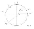
- FIG. 1 shows a schematic representation of the circular inner raceway 1, which has a circular arc section 2, which extends over an angular range ⁇ shown here 270 °.
- the circular arc section 2 itself has a constant arc radius r and a center M r .
- the transition section 4 is a straight line extending from the end 2 of tangent.
- a sector 5 wherein in the sector 5 itself a sector radius r a is formed and the sector radius r a is smaller than the circular arc radius r. Accordingly, the center of the sector 5 is offset from the center M ra of the circular arc section 2 in the radial direction R to the outside.
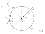
- FIG. 2 shows the lathe 6 according to the invention in a basic side view, wherein a mass 7 rotates on the inner race 1 in the direction of movement B.
- the mass 7 itself is shown here as a circular body with a mass radius r m , the mass radius r m being smaller than that in FIG FIG. 1 illustrated sector radius r a .
- a rotational movement D is performed around its own center.
- the occurring forces F are negligible within the scope of the invention.
- a respective centrifugal force F zx1 , F zx2 generated that cancel due to the constant radius r a of the arc section 2 together, so that the balance of forces is equal to zero.
- the deflection in the sector 5 causes a resultant force F res to be greater than the centrifugal force F zy .
- the force resultant is mainly on a straight line G, which is spanned by the center M r of the circular arc section 2 and the center M ra of the sector.
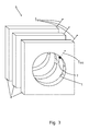
- FIG. 3 shows a perspective view of three spaced-apart parallel offset rib bodies 8, which form a lathe 6 according to the invention.
- a corresponding inner race 1 is formed in each rib body 8.
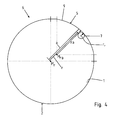
- FIG. 4 shows a further advantageous embodiment variant of the lathe 6 according to the invention, in which case an advantageous design feature is shown. Therefore, a resulting distance a from the circumferential line 9 of the sector 5 to the center M r of the circular arc section 2 is preferred. This distance a minus the radius r of the circular arc section 2 is smaller than the mass radius r M. By this feature, there is in particular no tilting in execution of the circumferential movement of the mass 7 on the inner raceway 1.
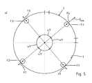
- each mass 7.1, 7.2, 7.3, 7.4 has an outwardly acting force F1, F2, F3, F4 due to the centrifugal force.
- the resultant of the mass 7.4 force F4 is due to the passage of the sector 5 slightly larger than the forces of the other masses F1, F2, F3. Consequently, the force-resultant F res is radially outward from the sector 5 acting.
- FIG. 5b illustrated force diagram of the free-cut forces F1, F2, F3, F4 and the resulting force F res clarifies. It can be seen that the forces F1 and F3 are opposite and equal in magnitude, with their lines of action being congruent. The forces F1 and F3 cancel each other out.
- the force F4 is slightly larger than the force F2, so that the resulting force F res arises from this.
- the force F res is shown shifted by a parallel shift in the image direction to the bottom right.
Landscapes
- Engineering & Computer Science (AREA)
- Mechanical Engineering (AREA)
- Rolling Contact Bearings (AREA)
Applications Claiming Priority (1)
| Application Number | Priority Date | Filing Date | Title |
|---|---|---|---|
| DE202014101732.1U DE202014101732U1 (de) | 2014-04-11 | 2014-04-11 | Drehmaschine |
Publications (2)
| Publication Number | Publication Date |
|---|---|
| EP2929947A2 true EP2929947A2 (fr) | 2015-10-14 |
| EP2929947A3 EP2929947A3 (fr) | 2015-12-23 |
Family
ID=53016460
Family Applications (1)
| Application Number | Title | Priority Date | Filing Date |
|---|---|---|---|
| EP15162930.0A Withdrawn EP2929947A3 (fr) | 2014-04-11 | 2015-04-09 | Machine rotative |
Country Status (2)
| Country | Link |
|---|---|
| EP (1) | EP2929947A3 (fr) |
| DE (1) | DE202014101732U1 (fr) |
Citations (1)
| Publication number | Priority date | Publication date | Assignee | Title |
|---|---|---|---|---|
| DE1691830U (de) | 1952-11-20 | 1955-01-20 | Schenk Bau G M B H | Unwuchtruettelvorrichtung zum erzeugen periodisch variierender beschleunigungen an technischen gebilden. |
Family Cites Families (6)
| Publication number | Priority date | Publication date | Assignee | Title |
|---|---|---|---|---|
| DE1041283B (de) * | 1952-11-19 | 1958-10-16 | Schenk Bau G M B H | Schwingungserreger |
| US2935282A (en) * | 1958-07-21 | 1960-05-03 | Norman R Lykes | Baby nursing bottle holder |
| GB881093A (en) * | 1959-06-08 | 1961-11-01 | J W And T H Carter Ltd | Improvements in and relating to vibrators |
| DE1187555B (de) * | 1961-03-27 | 1965-02-18 | Erich Baentsch | Unwucht-Schwingungserreger, vorzugsweise fuer eine Vorrichtung zum Eintreiben oder Ziehen von Pfaehlen, Spundbohlen, Rohren od. dgl. oder zum Verdichten des Baugrundes od. dgl. |
| DE2706667A1 (de) * | 1977-02-17 | 1979-01-11 | Bosch Gmbh Robert | Vibrationsgeraet zur bodenverdichtung |
| DE3519781A1 (de) * | 1985-06-03 | 1987-01-15 | Ekkehard Schmonses | Vorrichtung zum erzeugen gerichteter kraefte |
-
2014
- 2014-04-11 DE DE202014101732.1U patent/DE202014101732U1/de not_active Expired - Lifetime
-
2015
- 2015-04-09 EP EP15162930.0A patent/EP2929947A3/fr not_active Withdrawn
Patent Citations (1)
| Publication number | Priority date | Publication date | Assignee | Title |
|---|---|---|---|---|
| DE1691830U (de) | 1952-11-20 | 1955-01-20 | Schenk Bau G M B H | Unwuchtruettelvorrichtung zum erzeugen periodisch variierender beschleunigungen an technischen gebilden. |
Also Published As
| Publication number | Publication date |
|---|---|
| DE202014101732U1 (de) | 2015-07-14 |
| EP2929947A3 (fr) | 2015-12-23 |
Similar Documents
| Publication | Publication Date | Title |
|---|---|---|
| EP2652355B1 (fr) | Balancier à force centrifuge et disque d'accouplement muni de celui-ci | |
| DE112011100859B4 (de) | Torsionsschwingungsdämpfer | |
| DE102011076790B4 (de) | Antriebssystem für ein Fahrzeug | |
| DE102011016568B4 (de) | Fliehkraftpendel | |
| EP3341630A1 (fr) | Disque d'embrayage équipé d'un pendule a force centrifuge | |
| DE102012111323B4 (de) | Schwungrad eines Verbrennungsmotors | |
| EP3334955A1 (fr) | Dispositif de pendule à force centrifuge | |
| DE102017106112A1 (de) | Drehschwingungsdämpfer | |
| DE102012223563A1 (de) | Fliehkraftpendel | |
| DE102016110389A1 (de) | Elektromotor mit Schwingungsentkopplungsanordnung zur drehfesten Verbindung hin zum Getriebe | |
| DE102012217171B4 (de) | Hydrodynamische Kopplungsanordnung, insbesondere Drehmomentwandler | |
| DE102011103495A1 (de) | Kupplungswelle,Aktor,Nockenwellenverstellgetriebe und Nockenwellensteller | |
| DE102014220730A1 (de) | Drehschwingungsdämpfer | |
| EP2929947A2 (fr) | Machine rotative | |
| DE102017106231A1 (de) | Torsionsdämpfungseinrichtung | |
| DE102015201146A1 (de) | Harmonisches Getriebe | |
| DE102013003859A1 (de) | Gleichlaufgelenk | |
| WO2016062475A1 (fr) | Amortisseur de vibrations à masses antivibratoires et chaîne cinématique | |
| DE102014213862A1 (de) | Fliehkraftpendeleinrichtung und Drehmomentübertragungseinrichtung mit Fliehkraftpendeleinrichtung | |
| DE102018221837B4 (de) | Zahnrad für Elektrofahrzeuggetriebe und Elektrofahrzeuggetriebe | |
| DE102016124827A1 (de) | Fliehkraftpendeleinrichtung | |
| DE102013113294B4 (de) | Sinusförmig geformte Reibungsplatte für eine Nassreibungskupplung | |
| WO2017102198A1 (fr) | Volant d'inertie à deux masses | |
| DE102015017188B4 (de) | Spannungswellengetriebe | |
| DE102018128978A1 (de) | Schwungradeinrichtung mit einem Fliehkraftpendel |
Legal Events
| Date | Code | Title | Description |
|---|---|---|---|
| PUAI | Public reference made under article 153(3) epc to a published international application that has entered the european phase |
Free format text: ORIGINAL CODE: 0009012 |
|
| AK | Designated contracting states |
Kind code of ref document: A2 Designated state(s): AL AT BE BG CH CY CZ DE DK EE ES FI FR GB GR HR HU IE IS IT LI LT LU LV MC MK MT NL NO PL PT RO RS SE SI SK SM TR |
|
| AX | Request for extension of the european patent |
Extension state: BA ME |
|
| PUAL | Search report despatched |
Free format text: ORIGINAL CODE: 0009013 |
|
| AK | Designated contracting states |
Kind code of ref document: A3 Designated state(s): AL AT BE BG CH CY CZ DE DK EE ES FI FR GB GR HR HU IE IS IT LI LT LU LV MC MK MT NL NO PL PT RO RS SE SI SK SM TR |
|
| AX | Request for extension of the european patent |
Extension state: BA ME |
|
| RIC1 | Information provided on ipc code assigned before grant |
Ipc: B06B 1/16 20060101AFI20151116BHEP |
|
| STAA | Information on the status of an ep patent application or granted ep patent |
Free format text: STATUS: THE APPLICATION IS DEEMED TO BE WITHDRAWN |
|
| 18D | Application deemed to be withdrawn |
Effective date: 20160624 |