EP2929954B1 - Procédé de fabrication d'un arbre d'essieu léger à paroi variable avec bride soudée par friction - Google Patents
Procédé de fabrication d'un arbre d'essieu léger à paroi variable avec bride soudée par friction Download PDFInfo
- Publication number
- EP2929954B1 EP2929954B1 EP15162837.7A EP15162837A EP2929954B1 EP 2929954 B1 EP2929954 B1 EP 2929954B1 EP 15162837 A EP15162837 A EP 15162837A EP 2929954 B1 EP2929954 B1 EP 2929954B1
- Authority
- EP
- European Patent Office
- Prior art keywords
- die
- tool
- diameter
- axle shaft
- tubular blank
- Prior art date
- Legal status (The legal status is an assumption and is not a legal conclusion. Google has not performed a legal analysis and makes no representation as to the accuracy of the status listed.)
- Active
Links
Images


Classifications
-
- F—MECHANICAL ENGINEERING; LIGHTING; HEATING; WEAPONS; BLASTING
- F16—ENGINEERING ELEMENTS AND UNITS; GENERAL MEASURES FOR PRODUCING AND MAINTAINING EFFECTIVE FUNCTIONING OF MACHINES OR INSTALLATIONS; THERMAL INSULATION IN GENERAL
- F16C—SHAFTS; FLEXIBLE SHAFTS; ELEMENTS OR CRANKSHAFT MECHANISMS; ROTARY BODIES OTHER THAN GEARING ELEMENTS; BEARINGS
- F16C3/00—Shafts; Axles; Cranks; Eccentrics
- F16C3/02—Shafts; Axles
- F16C3/023—Shafts; Axles made of several parts, e.g. by welding
-
- B—PERFORMING OPERATIONS; TRANSPORTING
- B21—MECHANICAL METAL-WORKING WITHOUT ESSENTIALLY REMOVING MATERIAL; PUNCHING METAL
- B21K—MAKING FORGED OR PRESSED METAL PRODUCTS, e.g. HORSE-SHOES, RIVETS, BOLTS OR WHEELS
- B21K1/00—Making machine elements
- B21K1/06—Making machine elements axles or shafts
- B21K1/063—Making machine elements axles or shafts hollow
-
- B—PERFORMING OPERATIONS; TRANSPORTING
- B21—MECHANICAL METAL-WORKING WITHOUT ESSENTIALLY REMOVING MATERIAL; PUNCHING METAL
- B21C—MANUFACTURE OF METAL SHEETS, WIRE, RODS, TUBES, PROFILES OR LIKE SEMI-MANUFACTURED PRODUCTS OTHERWISE THAN BY ROLLING; AUXILIARY OPERATIONS USED IN CONNECTION WITH METAL-WORKING WITHOUT ESSENTIALLY REMOVING MATERIAL
- B21C1/00—Manufacture of metal sheets, wire, rods, tubes or like semi-manufactured products by drawing
- B21C1/16—Metal drawing by machines or apparatus in which the drawing action is effected by means other than drums, e.g. by a longitudinally-moved carriage pulling or pushing the work or stock for making metal sheets, rods or tubes
- B21C1/18—Metal drawing by machines or apparatus in which the drawing action is effected by means other than drums, e.g. by a longitudinally-moved carriage pulling or pushing the work or stock for making metal sheets, rods or tubes from stock of limited length
-
- B—PERFORMING OPERATIONS; TRANSPORTING
- B21—MECHANICAL METAL-WORKING WITHOUT ESSENTIALLY REMOVING MATERIAL; PUNCHING METAL
- B21C—MANUFACTURE OF METAL SHEETS, WIRE, RODS, TUBES, PROFILES OR LIKE SEMI-MANUFACTURED PRODUCTS OTHERWISE THAN BY ROLLING; AUXILIARY OPERATIONS USED IN CONNECTION WITH METAL-WORKING WITHOUT ESSENTIALLY REMOVING MATERIAL
- B21C1/00—Manufacture of metal sheets, wire, rods, tubes or like semi-manufactured products by drawing
- B21C1/16—Metal drawing by machines or apparatus in which the drawing action is effected by means other than drums, e.g. by a longitudinally-moved carriage pulling or pushing the work or stock for making metal sheets, rods or tubes
- B21C1/22—Metal drawing by machines or apparatus in which the drawing action is effected by means other than drums, e.g. by a longitudinally-moved carriage pulling or pushing the work or stock for making metal sheets, rods or tubes specially adapted for making tubular articles
- B21C1/24—Metal drawing by machines or apparatus in which the drawing action is effected by means other than drums, e.g. by a longitudinally-moved carriage pulling or pushing the work or stock for making metal sheets, rods or tubes specially adapted for making tubular articles by means of mandrels
-
- B—PERFORMING OPERATIONS; TRANSPORTING
- B21—MECHANICAL METAL-WORKING WITHOUT ESSENTIALLY REMOVING MATERIAL; PUNCHING METAL
- B21C—MANUFACTURE OF METAL SHEETS, WIRE, RODS, TUBES, PROFILES OR LIKE SEMI-MANUFACTURED PRODUCTS OTHERWISE THAN BY ROLLING; AUXILIARY OPERATIONS USED IN CONNECTION WITH METAL-WORKING WITHOUT ESSENTIALLY REMOVING MATERIAL
- B21C23/00—Extruding metal; Impact extrusion
- B21C23/02—Making uncoated products
- B21C23/04—Making uncoated products by direct extrusion
- B21C23/08—Making wire, rods or tubes
- B21C23/085—Making tubes
-
- B—PERFORMING OPERATIONS; TRANSPORTING
- B21—MECHANICAL METAL-WORKING WITHOUT ESSENTIALLY REMOVING MATERIAL; PUNCHING METAL
- B21C—MANUFACTURE OF METAL SHEETS, WIRE, RODS, TUBES, PROFILES OR LIKE SEMI-MANUFACTURED PRODUCTS OTHERWISE THAN BY ROLLING; AUXILIARY OPERATIONS USED IN CONNECTION WITH METAL-WORKING WITHOUT ESSENTIALLY REMOVING MATERIAL
- B21C37/00—Manufacture of metal sheets, rods, wire, tubes, profiles or like semi-manufactured products, not otherwise provided for; Manufacture of tubes of special shape
- B21C37/06—Manufacture of metal sheets, rods, wire, tubes, profiles or like semi-manufactured products, not otherwise provided for; Manufacture of tubes of special shape of tubes or metal hoses; Combined procedures for making tubes, e.g. for making multi-wall tubes
- B21C37/15—Making tubes of special shape; Making tube fittings
- B21C37/16—Making tubes with varying diameter in longitudinal direction
-
- F—MECHANICAL ENGINEERING; LIGHTING; HEATING; WEAPONS; BLASTING
- F16—ENGINEERING ELEMENTS AND UNITS; GENERAL MEASURES FOR PRODUCING AND MAINTAINING EFFECTIVE FUNCTIONING OF MACHINES OR INSTALLATIONS; THERMAL INSULATION IN GENERAL
- F16C—SHAFTS; FLEXIBLE SHAFTS; ELEMENTS OR CRANKSHAFT MECHANISMS; ROTARY BODIES OTHER THAN GEARING ELEMENTS; BEARINGS
- F16C2226/00—Joining parts; Fastening; Assembling or mounting parts
- F16C2226/30—Material joints
- F16C2226/36—Material joints by welding
-
- Y—GENERAL TAGGING OF NEW TECHNOLOGICAL DEVELOPMENTS; GENERAL TAGGING OF CROSS-SECTIONAL TECHNOLOGIES SPANNING OVER SEVERAL SECTIONS OF THE IPC; TECHNICAL SUBJECTS COVERED BY FORMER USPC CROSS-REFERENCE ART COLLECTIONS [XRACs] AND DIGESTS
- Y10—TECHNICAL SUBJECTS COVERED BY FORMER USPC
- Y10T—TECHNICAL SUBJECTS COVERED BY FORMER US CLASSIFICATION
- Y10T29/00—Metal working
- Y10T29/49—Method of mechanical manufacture
- Y10T29/49826—Assembling or joining
Definitions
- This invention relates to axle shafts.
- the invention relates to a method for forming a lightweight axle shaft having variable inner and outer diameters.
- Axle shafts are often subjected to significant loads.
- Vehicle drive axle shafts for example, transmit significant torque to the vehicle wheels and are subject to rapid starts and stops in operation. Because of the significant loads that are often imposed on axle shafts, most axle shafts are formed of solid metal to provide sufficient rigidity and strength. Solid axle shafts, however, require a significant amount of material and are relatively heavy. In vehicles, this weight has a negative effect on fuel economy and imposes additional loads on other vehicle components.
- the known method shown in US 5,213,250 A1 comprises inserting a first tubular blank having a leading end and a trailing end into a first die, the first die having an inlet end and an outlet end defining an extrusion throat through which the first tubular blank is extruded beginning with the leading end of the first tubular blank and ending with the trailing end of the first tubular blank; inserting a tool into the first die, the tool defining a surface configured to engage the trailing end of the first tubular blank and having a mandrel configured to be received within the extrusion throat of the first die and the first tubular blank, the mandrel having a first portion having a first diameter and a second portion having a second diameter greater than the first diameter; moving the tool within the first die such that the surface of the tool engages the trailing end of the first tubular blank and the first portion
- Axle shafts have also been developed as shown, for example, in US Patent No. 4,301,672 and US Patent No.4,277,969 .
- the inventor herein has recognized a need for a method for forming an axle shaft that will minimize and/or eliminate one or more of the above-identified deficiencies.
- This invention provides a method for forming an axle shaft as defined in claim 1.
- Optional features of the method are the subject of claims 2 to 15.
- a method for forming an axle shaft in accordance with one embodiment of the invention includes inserting a first tubular blank having a leading end and a trailing end into a die.
- the die has an inlet end and an outlet end defining an extrusion throat through which the first tubular blank is extruded beginning with the leading end of the first tubular blank and ending with the trailing end of the first tubular blank.
- the method further includes inserting a tool into the die.
- the tool defines a surface configured to engage the trailing end of the first tubular blank and a has a mandrel configured to be received within the extrusion throat of the die and the first tubular blank.
- the mandrel has a first portion having a first diameter and a second portion having a second diameter different from the first diameter.
- the method further includes moving the tool within the die such that the surface of the tool engages the trailing end of the first tubular blank and a leading end of the first portion of the mandrel exits the first tubular blank and extends beyond the leading end of the first tubular blank.
- the method further includes applying a force to the tool to move the tool toward the outlet end of the die and extrude the first tubular blank through the extrusion throat to form the axle shaft.
- a first end portion of the axle shaft assumes a shape having an outer diameter defined by the extrusion throat and an inner diameter defined by a trailing end of the first portion of the mandrel.
- An intermediate portion of the axle shaft assumes a shape having an outer diameter defined by the extrusion throat and inner diameter defined by the second portion of the mandrel.
- the method further includes withdrawing the tool from the die and inserting a second tubular blank having a leading end and a trailing end into the die. The leading end of the second tubular blank engages the trailing end of the first tub
- the method further includes reinserting the tool into the die and moving the tool within the die such that the surface of the tool engages the trailing end of the second tubular blank and a leading end of the first portion of the mandrel exits the second tubular blank and extends beyond the leading end of the second tubular blank into the trailing end of the first tubular blank.
- the method further includes, applying a force to the tool to move the tool toward the outlet end of the die such that a second end portion of the axle shaft assumes a shape having an outer diameter defined by the extrusion throat and an inner diameter defined by the leading end of the first portion of the mandrel.
- the method according to the invention includes inserting a second tool into the die.
- the second tool defines a surface configured to engage the trailing end of the second tubular blank and a has a mandrel configured to be received within the extrusion throat of the die and the first tubular blank.
- the mandrel of the second tool has a third diameter less than the second diameter.
- the method further includes moving the second tool within the die such that the surface of the second tool engages the trailing end of the second tubular blank and the mandrel of the second tool is disposed within the first tubular blank and the extrusion throat of the first die.
- the method further includes applying a force to the second tool to move the second tool towards the outlet end of the die such that a second end portion of the axle shaft assumes a shape having an outer diameter defined by the extrusion throat and an inner diameter defined by the mandrel of the second tool.
- the method further includes extruding a first end of the axle shaft through a second die to reduce a diameter of the first end of the axle shaft.
- the method further includes forming a plurality of splines on the first end of the axle shaft.
- the method further includes positioning a wheel flange such that the wheel flange engages a first end of the axle shaft.
- the method further includes rotating at least one of the axle shaft and the wheel flange relative to another of the axle shaft and the wheel flange to weld the axle shaft and the wheel flange together.
- the method further includes configuring a radially inner surface of a first end of the axle shaft to receive a seal.
- configuring the radially inner surface of the first end of the axle shaft comprises machining the radially inner surface to define at least one of internal threads or grooves to receive the seal.
- the method further includes applying heat to the axle shaft to harden the axle shaft.
- the method further includes applying a lubricant to the first tubular blank prior to inserting the first tubular blank into the first die.
- the second diameter of the second portion of the mandrel is greater than the first diameter of the first portion of the mandrel.
- the first die is tubular in shape and is pre-stressed.
- the first die includes a reduction zone immediately preceding the outlet end having a diameter that varies along a length of the first die to create an angled surface therein.
- the axle shaft defines a bore extending along at least a portion of the length of the axle shaft.
- At least one of an outer diameter and an inner diameter of the axle shaft varies along a length of the axle shaft to define a wall of varying thickness.
- FIG. 1-2 illustrate one embodiment of an axle shaft 10 that may be formed using a method in accordance with the present invention.
- Shaft 10 is particularly adapted for use in a vehicle drive axle and, more particularly, a rear drive axle. It should be understood, however, that the methods disclosed herein can be used in the formation of axle shafts for front drive axles and in other vehicular and non-vehicular power transmission applications.
- Shaft 10 may include a body 12 and a wheel flange 14.
- Body 12 may be used to transfer torque between a drive member and a driven member such as from a vehicle drivetrain (not shown) to one or more vehicle wheels (not shown).
- Body 12 may be made from conventional metals and metal alloys.
- Body 12 is elongate and is disposed about, and may be centered about, a rotational axis 16.
- One longitudinal end 18 of body 12 may be coupled to flange 14 and may be configured to support a vehicle wheel.
- the other longitudinal end 20 of body 12 may be coupled to a side gear (not shown) in a differential.
- the radially outer surface of end 20 may define a plurality of axially extending splines 22 configured to engage corresponding splines in a bore of side gear in order to couple shaft 10 for rotation with the side gear.
- the splines may be formed by, for example, rolling or swaging.
- Body 12 is also tubular or hollow in order to reduce the weight of axle shaft 10 relative to conventional solid axle shafts and defines a bore 24 extending along a portion or all of the length of body 12.
- the outer and/or inner diameters of body 12 may vary to define a wall 26 of varying thickness (and a bore 24 of varying diameter) along the length of body 12 in order to accommodate variations in loads along the length of body 12.
- the wall 26 at an end portion 27 of body 12 near end 18 may be relatively thick and have an outer diameter OD 1 and an inner diameter ID 1 .
- the inner diameter of wall 26 may increase such that wall 26 at an intermediate portion 28 of body 12 is relatively thin and has an outer diameter OD 2 equal to outer diameter OD 1 and an inner diameter ID 2 that is greater than inner diameter ID 1 .
- the inner diameter of wall 26 may decrease such that wall 26 at an intermediate portion 29 of body 12 is relatively thick and has an outer diameter OD 3 equal to outer diameter OD 1 and an inner diameter ID 3 that is less than inner diameter ID 2 .
- Inner diameter ID 3 may be equal to inner diameter ID 1 , but may also vary relative to inner diameter ID 1 .
- both the outer diameter and the inner diameter of wall 26 may decrease such that wall 26 at an end portion 30 of body 12 near end 20 of body 12 is relatively thick and has an outer diameter OD 4 that is less than outer diameter OD 1 and an inner diameter ID 4 that is less than inner diameters ID 2 and ID 3 .
- Inner diameter ID 4 may also be less than ID 1 .
- an end portion 31 of body 12 at end 20 of body 12 may also be relatively thick and have an outer diameter OD 5 equal to outer diameter OD 4 and an inner diameter ID 5 that is greater than inner diameter ID 4 for a purpose described hereinbelow.
- wall 26 shown in body 12 is exemplary only and that the inner and/or outer diameters of wall 18 may vary depending on the application to accommodate anticipated needs in terms of strength, packaging and other parameters.
- bore 24 may be machined at end 20 to define internal threads, grooves or other formations configured to receive a plug or other type of seal (not shown).
- Wheel flange 14 is provided to support a driven member such as a vehicle wheel and to couple the driven member to axle shaft 10 for rotation therewith.
- Flange 14 may be forged from conventional metals and metal alloys.
- Flange 14 includes an axially extending annular hub 32 that is configured for coupling to end 18 of body 12.
- An inboard end of hub 32 may be annular in shape and have inner and outer diameters equal to the inner and outer diameters ID 1 , OD 1 of end 18 of body 12.
- the outboard end of hub 32 may be closed to prevent foreign objects and elements from entering bore 24 in body 12.
- Flange 14 also includes a wheel mounting portion 34 that extends radially outwardly from hub 32.
- Portion 34 may be generally circular in shape and may include a plurality of bores (not shown) extending parallel to axis 16 and configured to receive bolts (not shown) used to support the vehicle wheel.
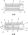
- the method may begin with the step of inserting a tubular blank 36 in a die 38.
- Blank 36 is made from conventional metals and metal alloys with a material composition and size selected depending on the needs of the application. Blank 36 may be cut to length from a longer pole of the selected material. Blank 36 has a leading end 40 and a trailing end 42 with leading end 40 inserted into die 38 before trailing end 42. Blank 36 also defines a bore 44 that extends along the length of blank 38 between ends 40, 42.
- a reactive forming lubricant may be applied to blank 36.
- Die 38 is tubular in shape, is pre-stressed, and defines an inlet end 46 and an outlet end 48.
- the opening formed an inlet end 46 has a diameter sized to receive blank 36 in an undeformed state.
- the opening formed at outlet end 48 has a diameter that is smaller than the diameter of the opening at inlet end 46 (and the undeformed blank 36) and comprises an extrusion throat 50 through which blank 36 is extruded beginning with leading end 40 of blank 36 and ending with trailing end 42 of blank 36.
- the area in die 38 immediately preceding outlet end 48 comprises a reduction zone and the diameter of this area may vary to create an angled surface to promote efficient material flow.
- Tool 52 may comprise a punch or similar tool.
- Tool 52 includes a body 54 and a mandrel 56 extending from body 54.
- Body 54 has a diameter that is about equal to the inner diameter of die 38 and the diameter of blank 36.
- Body 54 defines a surface 58 at one end configured to engage trailing end 42 of blank 36.
- Mandrel 56 is configured to be received within bore 44 of blank 36 and extrusion throat 50 of die 38.
- Mandrel 56 may have a varying diameter along its length.
- mandrel 56 includes a first portion 60 having a first diameter d 1 and a second portion 62 having a second diameter d 2 that is different from diameter d 1 .
- diameter d 2 is greater than diameter d 1 .
- mandrel 56 may have more than two portions having different diameters and that the diameters can increase or decrease moving from portion to portion along the length of mandrel 56. The method may continue with the step of moving tool 52 within die 38 such that surface 58 engages trailing end 42 of blank 36 and a leading end 64 of portion 60 of mandrel 56 exits blank 36 and extends beyond leading end 40 of blank 36.
- the method may continue with the step of applying a force to tool 52 to move tool 52 towards the outlet end 48 of die 38 and extrude blank 36 through throat 50 to begin forming the tubular body 12 of the axle shaft 10.
- the leading end 40 of blank 38 is extruded through die 38, the leading end collapses about mandrel 56 and one end portion 27 of the body 12 assumes a shape having an outer diameter defined by throat 50 and an inner diameter and length defined by a trailing end 66 of portion 60 of mandrel 56.
- portion 60 of mandrel 56 exits die 38 and portion 62 of mandrel 56 moves into and through throat 50 of die 38.
- an intermediate portion 28 of body 12 assumes a shape having an outer diameter defined by throat 50 and inner diameter and length defined by portion 62 of mandrel 56.
- a stepped or gradual transition portion may be formed between end portion 27 and intermediate portion 28 depending on the shape of mandrel 56.
- the method may continue with the steps of withdrawing tool 52 from die 38 and inserting another tubular blank 36A into die 38.
- Blank 36A is moved within die 38 until the leading end 40A of blank 36A engages the trailing end 42 of blank 36.
- the method may further continue with the steps of reinserting tool 52 into die 38 and moving tool 52 within die 38 until surface 58 of tool 52 engages the trailing end 42A of blank 36A.
- mandrel 56 extends through bore 44A of blank 36A and leading end 64 of portion 60 of mandrel 56 exits blank 36A and extends beyond leading end 40A of blank 36A into trailing end 42 of blank 36.
- a different tool 68 may be inserted into die 38.
- tool 68 includes a main body 70 with a surface 72 configured to engage trailing end 42A of blank 36A and a mandrel 74 configured to extend through bore 44A of blank 36A beyond leading end 40A of blank 36A and into trailing end 42 of blank 36.
- Using a different tool 68 permits further variation in the formation of the inner diameter of blank 36 and the wall thickness of body 12.
- mandrel 74 of tool 68 includes portions 76, 78 having diameters that differ from one another (with portion 78 having a larger diameter than portion 76 in the illustrated embodiment) and that may differ from portions 60, 62 of mandrel 56 on tool 52.
- portions 76, 78 are configured to form end 20 of body 12 in such a way that portion 30 of the end 20 is relatively thick to provide support for subsequent spline forming operations and/or formation of a ring groove for use in receiving a retaining clip used to prevent outboard movement of shaft 12 from the vehicle differential while another portion 31 of the end 20 is relatively thin to reduce the need for material removal when forming the inner diameter of end 20 to receive a plug or seal.
- the method may continue with the step of applying a force to tool 52 to move the tool 52 towards outlet end 48 of die 38 such that another end portion of body 12 of shaft 10 assumes a shape having an outer diameter defined by throat 50 and an inner diameter defined by the leading end 64 of portion 60 of mandrel 56.
- extrusion of blank 36A may begin in the same manner as blank 36. In the illustrated embodiment, the extrusion of blank 36A can begin without removal of tool 52.
- the method may similarly continue with the step of applying a force to tool 68 to move tool 68 towards outlet end 48 of die 38 such that end portion 30, 31 of body 12 of shaft 10 assumes a shape having an outer diameter defined by throat 50 and an inner diameter defined by portions 76, 78, respectively, of mandrel 74 of tool 68.
- tool 68 may be withdrawn and tool 52 reinserted and extrusion of blank 36A may begin in the same manner as blank 36.
- additional forming steps may be performed to produce an axle shaft suitable for use as a drive axle.
- the method may continue with the step of extruding one end 18 or 20 of body 12 through another die 80 to reduce the inner and outer diameters of end 18 or 20.
- the method may further continue with the step of forming a plurality of splines on end 20 through, for example, rolling, swaging or cutting operations to configure body 12 for coupling to a side gear of a vehicle differential.
- the method may include the step of configuring a radially inner surface of one or both ends 18, 20 of body 12.
- the inner surface of end 20 may be configured to receive a seal in order to plug bore 24 and prevent lubricant in the differential from entering bore 24 and thereby changing differential fluid dynamics and oil fill levels and prevent introduction of contaminants to the lubricant in the differential and the differential components.
- the method may also include several steps for assembling wheel flange 14 to body 12.
- the method may include the step of applying heat to body 12 in order to harden at least a portion of body 12 such as end 18. Heat may be generated, for example, through induction by inserting body 12 or a portion of body 12 within a coil and generating a current in the coil.
- the method may include the steps of positioning wheel flange 14 such that flange 14 engages end 18 of body 12 and rotating at least one of body 12 and wheel flange 14 relative to the other to generate sufficient head to melt the engagement surfaces of body 12 and wheel flange 14.
- the method may further include the step of applying an axial force to one or both of body 12 and wheel flange 14 to maintain engagement and pressure.
- the speed of rotation, the duration of rotation and the pressure applied may be varied depending upon the material composition of body 12 and flange 14, the surface roughness of the engaged surfaces and other factors.
- the method may further include the step of stopping rotation of the body 12 and/or wheel flange 14 to allow fusing of the molten engagement surfaces.
- the resulting weld is continuous and homogenous. Some material from the melted surfaces forms flashing and what is commonly referred as a "ram's horn.” Any material displaced inwardly within bore 24 of body 12 solidifies and remains within bore 24. Any material displaced outwardly, commonly may be removed by shearing or another machining operation.
- a method for forming an axle shaft 10 in accordance with the present invention represent an improvement relative to conventional methods.
- the inventive method allows rapid production of axle shafts 10 while also allowing the shafts 10 to be formed with varying inner and outer diameters.
- the inventive method permits formation of a hollow axle shaft 10 with relatively thick end sections 18, 20 to accommodate loads from coupling the ends 18, 20 of the axle shaft 10 to other components.
- the method permits a relatively thick wall at the wheel flange joint thereby increasing weld joint strength.
Landscapes
- Engineering & Computer Science (AREA)
- Mechanical Engineering (AREA)
- General Engineering & Computer Science (AREA)
- Ocean & Marine Engineering (AREA)
- Shafts, Cranks, Connecting Bars, And Related Bearings (AREA)
- Pressure Welding/Diffusion-Bonding (AREA)
- Extrusion Of Metal (AREA)
- Forging (AREA)
- Heat Treatment Of Articles (AREA)
Claims (15)
- Procédé de formation d'un arbre d'essieu (10), comprenant :l'insertion d'une première ébauche tubulaire (36) ayant une extrémité d'attaque (40) et une extrémité de fuite (42) dans une première filière (38), la première filière ayant une extrémité d'admission (46) et une extrémité de refoulement (48) définissant une gorge d'extrusion (50) à travers laquelle la première ébauche tubulaire est extrudée en commençant avec l'extrémité d'attaque de la première ébauche tubulaire et en terminant avec l'extrémité de fuite de la première ébauche tubulaire ;l'insertion d'un premier outil (52) dans la première filière, le premier outil définissant une surface (58) configurée pour s'engager avec l'extrémité d'attaque de la première ébauche tubulaire et ayant un mandrin (56) configuré pour être reçu au sein de la gorge d'extrusion de la première filière et de la première ébauche tubulaire, le mandrin ayant une première portion (60) ayant un premier diamètre (d1) et une seconde portion (62) ayant un deuxième diamètre (d2) plus grand que le premier diamètre ;le déplacement du premier outil au sein de la première filière de telle sorte que la surface du premier outil s'engage avec l'extrémité d'attaque de la première ébauche tubulaire et la première portion du mandrin soit disposée au sein de la première ébauche tubulaire et de la gorge d'extrusion de la première filière ;l'application d'une force au premier outil pour déplacer le premier outil vers l'extrémité de refoulement de la première filière et extruder la première ébauche tubulaire à travers la gorge d'extrusion pour former l'arbre d'essieu, une première portion d'extrémité de l'arbre d'essieu adoptant une forme ayant un diamètre externe défini par la gorge d'extrusion et un diamètre interne défini par la première portion du mandrin et une première portion intermédiaire de l'arbre d'essieu adoptant une forme ayant un diamètre externe défini par la gorge d'extrusion et un diamètre interne défini par la seconde portion du mandrin ;le retrait du premier outil de la première filière ; et l'insertion d'une seconde ébauche tubulaire (36A) ayant une extrémité d'attaque (40A) et une extrémité de fuite (42A) dans la première filière, l'extrémité d'attaque de la seconde ébauche tubulaire s'engageant avec l'extrémité de fuite de la première ébauche tubulaire ;l'insertion d'un second outil (68) dans la première filière, le second outil définissant une surface (72) configurée pour s'engager avec l'extrémité de fuite de la seconde ébauche tubulaire et ayant un mandrin (74) configuré pour être reçu au sein de la gorge d'extrusion de la première filière et de la première ébauche tubulaire, le mandrin du second outil ayant un troisième diamètre qui est plus petit que le deuxième diamètre ;le déplacement du second outil au sein de la première filière pour que la surface du second outil s'engage avec l'extrémité de fuite de la seconde ébauche tubulaire et le mandrin du second outil soit disposé au sein de la première ébauche tubulaire et de la gorge d'extrusion de la première filière ; etl'application d'une force au second outil pour déplacer le second outil vers l'extrémité de refoulement de la première filière pour qu'une seconde portion d'extrémité de l'arbre d'essieu adopte une forme ayant un diamètre externe défini par la gorge d'extrusion et un diamètre interne défini par le mandrin du second outil.
- Procédé selon la revendication 1, comprenant en outre l'extrusion d'une première extrémité (18 ; 20) de l'arbre d'essieu à travers une seconde filière pour réduire un diamètre de la première extrémité de l'arbre d'essieu.
- Procédé selon la revendication 1 ou 2, comprenant en outre la formation d'une pluralité de cannelures sur la première extrémité de l'arbre d'essieu.
- Procédé selon la revendication 1, comprenant en outre le positionnement d'un flasque de roue (14) de telle sorte que le flasque de roue s'engage avec une première extrémité (18) de l'arbre d'essieu ; et
la rotation d'au moins l'un de l'arbre d'essieu et du flasque de roue par rapport à un autre de l'arbre d'essieu et du flasque de roue pour souder l'arbre d'essieu et le flasque de roue ensemble. - Procédé selon la revendication 1, comprenant en outre la configuration d'une surface radialement interne d'une première extrémité (20) de l'arbre d'essieu pour recevoir un joint.
- Procédé selon la revendication 5, dans lequel la configuration de la surface radialement interne de la première extrémité de l'arbre d'essieu comprend l'usinage de la surface radialement interne pour définir au moins un élément parmi des filets internes ou des rainures pour recevoir le joint.
- Procédé selon la revendication 1, comprenant en outre l'application de chaleur à l'arbre d'essieu pour durcir l'arbre d'essieu.
- Procédé selon la revendication 1, comprenant en outre l'application d'un lubrifiant à la première ébauche tubulaire avant l'insertion de la première ébauche tubulaire dans la première filière.
- Procédé selon l'une quelconque des revendications précédentes, dans lequel le deuxième diamètre de la seconde portion du mandrin est plus grand que le premier diamètre de la première portion du mandrin.
- Procédé selon l'une quelconque des revendications précédentes, dans lequel la première filière est de forme tubulaire et est précontrainte.
- Procédé selon l'une quelconque des revendications précédentes, dans lequel la première filière inclut une zone de réduction précédant immédiatement l'extrémité de refoulement ayant un diamètre qui varie suivant une longueur de la première filière pour y définir une surface inclinée.
- Procédé selon l'une quelconque des revendications précédentes, dans lequel le mandrin du second outil a une première portion (76) ayant le troisième diamètre et une seconde portion (78) ayant un quatrième diamètre.
- Procédé selon la revendication 12, dans lequel le quatrième diamètre est plus grand que le troisième diamètre.
- Procédé selon la revendication 12 ou 13, dans lequel le deuxième diamètre est différent du quatrième diamètre.
- Procédé selon l'une quelconque des revendications 12 à 14, dans lequel le premier diamètre est différent du troisième diamètre.
Applications Claiming Priority (1)
| Application Number | Priority Date | Filing Date | Title |
|---|---|---|---|
| US14/247,709 US9400009B2 (en) | 2014-04-08 | 2014-04-08 | Method for forming a variable wall light weight axle shaft with friction welded flange |
Publications (2)
| Publication Number | Publication Date |
|---|---|
| EP2929954A1 EP2929954A1 (fr) | 2015-10-14 |
| EP2929954B1 true EP2929954B1 (fr) | 2018-06-06 |
Family
ID=52824105
Family Applications (1)
| Application Number | Title | Priority Date | Filing Date |
|---|---|---|---|
| EP15162837.7A Active EP2929954B1 (fr) | 2014-04-08 | 2015-04-08 | Procédé de fabrication d'un arbre d'essieu léger à paroi variable avec bride soudée par friction |
Country Status (8)
| Country | Link |
|---|---|
| US (1) | US9400009B2 (fr) |
| EP (1) | EP2929954B1 (fr) |
| JP (1) | JP6305625B2 (fr) |
| CN (1) | CN106660092B (fr) |
| CA (1) | CA2945122A1 (fr) |
| HU (1) | HUE038954T2 (fr) |
| MX (1) | MX375912B (fr) |
| WO (1) | WO2015157092A1 (fr) |
Families Citing this family (8)
| Publication number | Priority date | Publication date | Assignee | Title |
|---|---|---|---|---|
| US9630451B2 (en) | 2014-06-18 | 2017-04-25 | American Axle & Manufacturing, Inc. | Method of manufacturing hollow axle shaft for a vehicle |
| US9327363B2 (en) | 2014-07-25 | 2016-05-03 | Arvinmeritor Technology, Llc | Method of making a bracket assembly for a brake assembly |
| HUE054565T2 (hu) | 2014-12-17 | 2021-09-28 | American Axle & Mfg Inc | Eljárás csõ elõállítására |
| JP2019519725A (ja) * | 2016-05-11 | 2019-07-11 | ペーター フックス テクノロジー グループ アクチェンゲゼルシャフト | 高圧導管 |
| CN108730294B (zh) * | 2018-06-25 | 2020-07-17 | 浙江劳士顿科技股份有限公司 | 用于焊接机器人关节的销轴及销轴装配装置 |
| JP6581737B1 (ja) * | 2019-02-27 | 2019-09-25 | 株式会社ショーワ | 動力伝達軸用の管体及び動力伝達軸 |
| US12214395B2 (en) * | 2019-09-06 | 2025-02-04 | Sango Co., Ltd. | Extrusion molding method for differential thickness pipe and extrusion molding apparatus for differential thickness pipe |
| TWI878928B (zh) * | 2023-06-20 | 2025-04-01 | 建興安泰工業股份有限公司 | 管材成型的方法 |
Family Cites Families (22)
| Publication number | Priority date | Publication date | Assignee | Title |
|---|---|---|---|---|
| US3631585A (en) | 1966-10-17 | 1972-01-04 | North American Rockwell | Method of making a friction-welded drive axle shaft having an annular section of flash metal |
| US3886649A (en) | 1973-08-01 | 1975-06-03 | Joseph A Simon | Process for cold forming a metal tube with an inwardly thickened end |
| US4087038A (en) | 1975-12-19 | 1978-05-02 | Harima Sargyo Kabushiki Kaisha | Frictional welding method |
| US4223825A (en) | 1979-03-30 | 1980-09-23 | The Marmon Group, Inc. | Method of forming a vehicle axle assembly |
| US4277969A (en) | 1979-10-24 | 1981-07-14 | Simon Joseph A | Method of cold forming tubes with interior thicker wall sections |
| US4301672A (en) | 1979-10-24 | 1981-11-24 | Simon Joseph A | Process for forming semi-float axle tubes and the like |
| US4487357A (en) | 1982-05-24 | 1984-12-11 | Simon Joseph A | Method for forming well drill tubing |
| US4435972A (en) * | 1982-06-28 | 1984-03-13 | Simon Joseph A | Process for forming integral spindle-axle tubes |
| US4659005A (en) | 1984-08-17 | 1987-04-21 | Spindler Dietmar E | Method of manufacturing axle assemblies |
| US5105644A (en) * | 1990-07-09 | 1992-04-21 | Simon Joseph A | Light weight drive shaft |
| US5303985A (en) | 1991-09-23 | 1994-04-19 | Dana Corporation | Cast one-piece axle housing |
| US5213250A (en) | 1991-12-19 | 1993-05-25 | Simon Joseph A | Method for forming a lightweight flanged axle shaft |
| US5205464A (en) | 1991-12-19 | 1993-04-27 | Joseph Simon | Method for forming a lightweight flanged axle shaft |
| US5522246A (en) * | 1995-04-19 | 1996-06-04 | U.S. Manufacturing Corporation | Process for forming light-weight tublar axles |
| US6439672B1 (en) | 2000-09-11 | 2002-08-27 | U.S. Manufacturing Corporation | Vehicle light weight dead axle and method for forming same |
| US20040060385A1 (en) | 2002-09-16 | 2004-04-01 | Prucher Bryan P. | One-piece axle tube housing assembly |
| CA2526117C (fr) | 2004-10-28 | 2014-04-15 | Copperweld Canada Inc. | Ensemble de carter d'essieu tubulaire avec epaisseur de paroi variable |
| US7485044B2 (en) | 2005-02-17 | 2009-02-03 | General Motors Corporation | Shaft assembly and method of manufacture thereof |
| US20070204668A1 (en) | 2006-03-03 | 2007-09-06 | Minako Matsuoka | Method and apparatus for plastic working of hollow rack bar and hollow rack bar |
| KR20080030821A (ko) | 2006-10-02 | 2008-04-07 | 한국델파이주식회사 | 자동차용 드라이브 샤프트 |
| CN102240688B (zh) * | 2011-05-13 | 2013-07-03 | 北京机电研究所 | 后桥整体车轴快捷挤压成形的方法 |
| KR20130013546A (ko) | 2011-07-28 | 2013-02-06 | 현대제철 주식회사 | 심리스 파이프로 형성되는 액슬 샤프트 및 이의 제조 방법 |
-
2014
- 2014-04-08 US US14/247,709 patent/US9400009B2/en active Active
-
2015
- 2015-04-02 JP JP2017505054A patent/JP6305625B2/ja active Active
- 2015-04-02 CN CN201580018666.2A patent/CN106660092B/zh active Active
- 2015-04-02 MX MX2016013139A patent/MX375912B/es active IP Right Grant
- 2015-04-02 WO PCT/US2015/024139 patent/WO2015157092A1/fr not_active Ceased
- 2015-04-02 CA CA2945122A patent/CA2945122A1/fr not_active Abandoned
- 2015-04-08 HU HUE15162837A patent/HUE038954T2/hu unknown
- 2015-04-08 EP EP15162837.7A patent/EP2929954B1/fr active Active
Non-Patent Citations (1)
| Title |
|---|
| None * |
Also Published As
| Publication number | Publication date |
|---|---|
| WO2015157092A1 (fr) | 2015-10-15 |
| CN106660092B (zh) | 2019-04-16 |
| JP2017519642A (ja) | 2017-07-20 |
| US20150285297A1 (en) | 2015-10-08 |
| CA2945122A1 (fr) | 2015-10-15 |
| US9400009B2 (en) | 2016-07-26 |
| HUE038954T2 (hu) | 2018-12-28 |
| MX2016013139A (es) | 2017-04-27 |
| CN106660092A (zh) | 2017-05-10 |
| MX375912B (es) | 2025-03-07 |
| JP6305625B2 (ja) | 2018-04-04 |
| EP2929954A1 (fr) | 2015-10-14 |
Similar Documents
| Publication | Publication Date | Title |
|---|---|---|
| EP2929954B1 (fr) | Procédé de fabrication d'un arbre d'essieu léger à paroi variable avec bride soudée par friction | |
| EP2929953B1 (fr) | Procédé de fabrication d'un arbre d'essieu léger à paroi variable avec un élément de bride intégré | |
| US5213250A (en) | Method for forming a lightweight flanged axle shaft | |
| CN107250390B (zh) | 制造管件的方法和其中使用的机器 | |
| US5205464A (en) | Method for forming a lightweight flanged axle shaft | |
| US5105644A (en) | Light weight drive shaft | |
| EP3020993A2 (fr) | Procédé de fabrication d'un arbre de transmission de couple | |
| EP2960004A1 (fr) | Système et procédé de soudage par friction d'une pièce à usiner | |
| CN110802374B (zh) | 一种变截面汽车驱动桥壳的制造方法 | |
| EP1065131A2 (fr) | Direction à crémaillère et procédé de fabrication d'un pignon à dentelure inclinée | |
| EP2930044B1 (fr) | Arbre d'essieu moteur léger | |
| WO2015195781A1 (fr) | Arbre d'essieu creux pour un véhicule et procédé de fabrication associé | |
| US10352374B2 (en) | Method of forming and machining a clutch hub | |
| KR20060116099A (ko) | 자동차용 유니버셜 조인트 및 그 제조방법 | |
| US8701454B2 (en) | Flow form tool mandrel | |
| WO2018020445A1 (fr) | Poutre d'essieu à épaisseur de paroi variable et/ou à forme de section transversale variable et procédé de fabrication correspondant | |
| US5408857A (en) | Method and apparatus for extrusion of gears | |
| CN222198350U (zh) | 一种管坯成形异形内花键轴冷挤压成形模具 | |
| CN120133325A (zh) | 一种管坯成形异形内花键轴冷挤压成形工艺 |
Legal Events
| Date | Code | Title | Description |
|---|---|---|---|
| PUAI | Public reference made under article 153(3) epc to a published international application that has entered the european phase |
Free format text: ORIGINAL CODE: 0009012 |
|
| AK | Designated contracting states |
Kind code of ref document: A1 Designated state(s): AL AT BE BG CH CY CZ DE DK EE ES FI FR GB GR HR HU IE IS IT LI LT LU LV MC MK MT NL NO PL PT RO RS SE SI SK SM TR |
|
| AX | Request for extension of the european patent |
Extension state: BA ME |
|
| 17P | Request for examination filed |
Effective date: 20160413 |
|
| RBV | Designated contracting states (corrected) |
Designated state(s): AL AT BE BG CH CY CZ DE DK EE ES FI FR GB GR HR HU IE IS IT LI LT LU LV MC MK MT NL NO PL PT RO RS SE SI SK SM TR |
|
| GRAP | Despatch of communication of intention to grant a patent |
Free format text: ORIGINAL CODE: EPIDOSNIGR1 |
|
| STAA | Information on the status of an ep patent application or granted ep patent |
Free format text: STATUS: GRANT OF PATENT IS INTENDED |
|
| INTG | Intention to grant announced |
Effective date: 20170511 |
|
| GRAJ | Information related to disapproval of communication of intention to grant by the applicant or resumption of examination proceedings by the epo deleted |
Free format text: ORIGINAL CODE: EPIDOSDIGR1 |
|
| STAA | Information on the status of an ep patent application or granted ep patent |
Free format text: STATUS: REQUEST FOR EXAMINATION WAS MADE |
|
| INTC | Intention to grant announced (deleted) | ||
| GRAS | Grant fee paid |
Free format text: ORIGINAL CODE: EPIDOSNIGR3 |
|
| STAA | Information on the status of an ep patent application or granted ep patent |
Free format text: STATUS: GRANT OF PATENT IS INTENDED |
|
| GRAP | Despatch of communication of intention to grant a patent |
Free format text: ORIGINAL CODE: EPIDOSNIGR1 |
|
| INTG | Intention to grant announced |
Effective date: 20171222 |
|
| RAP1 | Party data changed (applicant data changed or rights of an application transferred) |
Owner name: AAM INTERNATIONAL S.A.R.L. |
|
| GRAA | (expected) grant |
Free format text: ORIGINAL CODE: 0009210 |
|
| STAA | Information on the status of an ep patent application or granted ep patent |
Free format text: STATUS: THE PATENT HAS BEEN GRANTED |
|
| AK | Designated contracting states |
Kind code of ref document: B1 Designated state(s): AL AT BE BG CH CY CZ DE DK EE ES FI FR GB GR HR HU IE IS IT LI LT LU LV MC MK MT NL NO PL PT RO RS SE SI SK SM TR |
|
| REG | Reference to a national code |
Ref country code: GB Ref legal event code: FG4D |
|
| REG | Reference to a national code |
Ref country code: CH Ref legal event code: EP Ref country code: AT Ref legal event code: REF Ref document number: 1005490 Country of ref document: AT Kind code of ref document: T Effective date: 20180615 |
|
| REG | Reference to a national code |
Ref country code: IE Ref legal event code: FG4D |
|
| REG | Reference to a national code |
Ref country code: DE Ref legal event code: R096 Ref document number: 602015011590 Country of ref document: DE |
|
| REG | Reference to a national code |
Ref country code: NL Ref legal event code: MP Effective date: 20180606 |
|
| REG | Reference to a national code |
Ref country code: LT Ref legal event code: MG4D |
|
| PG25 | Lapsed in a contracting state [announced via postgrant information from national office to epo] |
Ref country code: LT Free format text: LAPSE BECAUSE OF FAILURE TO SUBMIT A TRANSLATION OF THE DESCRIPTION OR TO PAY THE FEE WITHIN THE PRESCRIBED TIME-LIMIT Effective date: 20180606 Ref country code: CY Free format text: LAPSE BECAUSE OF FAILURE TO SUBMIT A TRANSLATION OF THE DESCRIPTION OR TO PAY THE FEE WITHIN THE PRESCRIBED TIME-LIMIT Effective date: 20180606 Ref country code: SE Free format text: LAPSE BECAUSE OF FAILURE TO SUBMIT A TRANSLATION OF THE DESCRIPTION OR TO PAY THE FEE WITHIN THE PRESCRIBED TIME-LIMIT Effective date: 20180606 Ref country code: BG Free format text: LAPSE BECAUSE OF FAILURE TO SUBMIT A TRANSLATION OF THE DESCRIPTION OR TO PAY THE FEE WITHIN THE PRESCRIBED TIME-LIMIT Effective date: 20180906 Ref country code: NO Free format text: LAPSE BECAUSE OF FAILURE TO SUBMIT A TRANSLATION OF THE DESCRIPTION OR TO PAY THE FEE WITHIN THE PRESCRIBED TIME-LIMIT Effective date: 20180906 Ref country code: FI Free format text: LAPSE BECAUSE OF FAILURE TO SUBMIT A TRANSLATION OF THE DESCRIPTION OR TO PAY THE FEE WITHIN THE PRESCRIBED TIME-LIMIT Effective date: 20180606 Ref country code: ES Free format text: LAPSE BECAUSE OF FAILURE TO SUBMIT A TRANSLATION OF THE DESCRIPTION OR TO PAY THE FEE WITHIN THE PRESCRIBED TIME-LIMIT Effective date: 20180606 |
|
| PG25 | Lapsed in a contracting state [announced via postgrant information from national office to epo] |
Ref country code: GR Free format text: LAPSE BECAUSE OF FAILURE TO SUBMIT A TRANSLATION OF THE DESCRIPTION OR TO PAY THE FEE WITHIN THE PRESCRIBED TIME-LIMIT Effective date: 20180907 Ref country code: HR Free format text: LAPSE BECAUSE OF FAILURE TO SUBMIT A TRANSLATION OF THE DESCRIPTION OR TO PAY THE FEE WITHIN THE PRESCRIBED TIME-LIMIT Effective date: 20180606 Ref country code: LV Free format text: LAPSE BECAUSE OF FAILURE TO SUBMIT A TRANSLATION OF THE DESCRIPTION OR TO PAY THE FEE WITHIN THE PRESCRIBED TIME-LIMIT Effective date: 20180606 Ref country code: RS Free format text: LAPSE BECAUSE OF FAILURE TO SUBMIT A TRANSLATION OF THE DESCRIPTION OR TO PAY THE FEE WITHIN THE PRESCRIBED TIME-LIMIT Effective date: 20180606 |
|
| REG | Reference to a national code |
Ref country code: AT Ref legal event code: MK05 Ref document number: 1005490 Country of ref document: AT Kind code of ref document: T Effective date: 20180606 |
|
| REG | Reference to a national code |
Ref country code: HU Ref legal event code: AG4A Ref document number: E038954 Country of ref document: HU |
|
| PG25 | Lapsed in a contracting state [announced via postgrant information from national office to epo] |
Ref country code: NL Free format text: LAPSE BECAUSE OF FAILURE TO SUBMIT A TRANSLATION OF THE DESCRIPTION OR TO PAY THE FEE WITHIN THE PRESCRIBED TIME-LIMIT Effective date: 20180606 |
|
| PG25 | Lapsed in a contracting state [announced via postgrant information from national office to epo] |
Ref country code: AT Free format text: LAPSE BECAUSE OF FAILURE TO SUBMIT A TRANSLATION OF THE DESCRIPTION OR TO PAY THE FEE WITHIN THE PRESCRIBED TIME-LIMIT Effective date: 20180606 Ref country code: IS Free format text: LAPSE BECAUSE OF FAILURE TO SUBMIT A TRANSLATION OF THE DESCRIPTION OR TO PAY THE FEE WITHIN THE PRESCRIBED TIME-LIMIT Effective date: 20181006 Ref country code: EE Free format text: LAPSE BECAUSE OF FAILURE TO SUBMIT A TRANSLATION OF THE DESCRIPTION OR TO PAY THE FEE WITHIN THE PRESCRIBED TIME-LIMIT Effective date: 20180606 Ref country code: RO Free format text: LAPSE BECAUSE OF FAILURE TO SUBMIT A TRANSLATION OF THE DESCRIPTION OR TO PAY THE FEE WITHIN THE PRESCRIBED TIME-LIMIT Effective date: 20180606 Ref country code: SK Free format text: LAPSE BECAUSE OF FAILURE TO SUBMIT A TRANSLATION OF THE DESCRIPTION OR TO PAY THE FEE WITHIN THE PRESCRIBED TIME-LIMIT Effective date: 20180606 Ref country code: CZ Free format text: LAPSE BECAUSE OF FAILURE TO SUBMIT A TRANSLATION OF THE DESCRIPTION OR TO PAY THE FEE WITHIN THE PRESCRIBED TIME-LIMIT Effective date: 20180606 Ref country code: PL Free format text: LAPSE BECAUSE OF FAILURE TO SUBMIT A TRANSLATION OF THE DESCRIPTION OR TO PAY THE FEE WITHIN THE PRESCRIBED TIME-LIMIT Effective date: 20180606 |
|
| PG25 | Lapsed in a contracting state [announced via postgrant information from national office to epo] |
Ref country code: SM Free format text: LAPSE BECAUSE OF FAILURE TO SUBMIT A TRANSLATION OF THE DESCRIPTION OR TO PAY THE FEE WITHIN THE PRESCRIBED TIME-LIMIT Effective date: 20180606 Ref country code: IT Free format text: LAPSE BECAUSE OF FAILURE TO SUBMIT A TRANSLATION OF THE DESCRIPTION OR TO PAY THE FEE WITHIN THE PRESCRIBED TIME-LIMIT Effective date: 20180606 |
|
| REG | Reference to a national code |
Ref country code: DE Ref legal event code: R097 Ref document number: 602015011590 Country of ref document: DE |
|
| PLBE | No opposition filed within time limit |
Free format text: ORIGINAL CODE: 0009261 |
|
| STAA | Information on the status of an ep patent application or granted ep patent |
Free format text: STATUS: NO OPPOSITION FILED WITHIN TIME LIMIT |
|
| 26N | No opposition filed |
Effective date: 20190307 |
|
| PG25 | Lapsed in a contracting state [announced via postgrant information from national office to epo] |
Ref country code: SI Free format text: LAPSE BECAUSE OF FAILURE TO SUBMIT A TRANSLATION OF THE DESCRIPTION OR TO PAY THE FEE WITHIN THE PRESCRIBED TIME-LIMIT Effective date: 20180606 Ref country code: DK Free format text: LAPSE BECAUSE OF FAILURE TO SUBMIT A TRANSLATION OF THE DESCRIPTION OR TO PAY THE FEE WITHIN THE PRESCRIBED TIME-LIMIT Effective date: 20180606 |
|
| PG25 | Lapsed in a contracting state [announced via postgrant information from national office to epo] |
Ref country code: AL Free format text: LAPSE BECAUSE OF FAILURE TO SUBMIT A TRANSLATION OF THE DESCRIPTION OR TO PAY THE FEE WITHIN THE PRESCRIBED TIME-LIMIT Effective date: 20180606 |
|
| REG | Reference to a national code |
Ref country code: CH Ref legal event code: PL |
|
| REG | Reference to a national code |
Ref country code: BE Ref legal event code: MM Effective date: 20190430 |
|
| GBPC | Gb: european patent ceased through non-payment of renewal fee |
Effective date: 20190408 |
|
| PG25 | Lapsed in a contracting state [announced via postgrant information from national office to epo] |
Ref country code: MC Free format text: LAPSE BECAUSE OF FAILURE TO SUBMIT A TRANSLATION OF THE DESCRIPTION OR TO PAY THE FEE WITHIN THE PRESCRIBED TIME-LIMIT Effective date: 20180606 Ref country code: LU Free format text: LAPSE BECAUSE OF NON-PAYMENT OF DUE FEES Effective date: 20190408 |
|
| PG25 | Lapsed in a contracting state [announced via postgrant information from national office to epo] |
Ref country code: GB Free format text: LAPSE BECAUSE OF NON-PAYMENT OF DUE FEES Effective date: 20190408 Ref country code: LI Free format text: LAPSE BECAUSE OF NON-PAYMENT OF DUE FEES Effective date: 20190430 Ref country code: CH Free format text: LAPSE BECAUSE OF NON-PAYMENT OF DUE FEES Effective date: 20190430 |
|
| PG25 | Lapsed in a contracting state [announced via postgrant information from national office to epo] |
Ref country code: BE Free format text: LAPSE BECAUSE OF NON-PAYMENT OF DUE FEES Effective date: 20190430 Ref country code: FR Free format text: LAPSE BECAUSE OF NON-PAYMENT OF DUE FEES Effective date: 20190430 |
|
| PG25 | Lapsed in a contracting state [announced via postgrant information from national office to epo] |
Ref country code: TR Free format text: LAPSE BECAUSE OF FAILURE TO SUBMIT A TRANSLATION OF THE DESCRIPTION OR TO PAY THE FEE WITHIN THE PRESCRIBED TIME-LIMIT Effective date: 20180606 |
|
| PG25 | Lapsed in a contracting state [announced via postgrant information from national office to epo] |
Ref country code: IE Free format text: LAPSE BECAUSE OF NON-PAYMENT OF DUE FEES Effective date: 20190408 |
|
| PG25 | Lapsed in a contracting state [announced via postgrant information from national office to epo] |
Ref country code: PT Free format text: LAPSE BECAUSE OF FAILURE TO SUBMIT A TRANSLATION OF THE DESCRIPTION OR TO PAY THE FEE WITHIN THE PRESCRIBED TIME-LIMIT Effective date: 20181008 |
|
| PG25 | Lapsed in a contracting state [announced via postgrant information from national office to epo] |
Ref country code: MT Free format text: LAPSE BECAUSE OF FAILURE TO SUBMIT A TRANSLATION OF THE DESCRIPTION OR TO PAY THE FEE WITHIN THE PRESCRIBED TIME-LIMIT Effective date: 20180606 |
|
| PG25 | Lapsed in a contracting state [announced via postgrant information from national office to epo] |
Ref country code: MK Free format text: LAPSE BECAUSE OF FAILURE TO SUBMIT A TRANSLATION OF THE DESCRIPTION OR TO PAY THE FEE WITHIN THE PRESCRIBED TIME-LIMIT Effective date: 20180606 |
|
| P01 | Opt-out of the competence of the unified patent court (upc) registered |
Effective date: 20230601 |
|
| P02 | Opt-out of the competence of the unified patent court (upc) changed |
Effective date: 20230602 |
|
| PGFP | Annual fee paid to national office [announced via postgrant information from national office to epo] |
Ref country code: HU Payment date: 20230421 Year of fee payment: 9 |
|
| PG25 | Lapsed in a contracting state [announced via postgrant information from national office to epo] |
Ref country code: HU Free format text: LAPSE BECAUSE OF NON-PAYMENT OF DUE FEES Effective date: 20240409 |
|
| PG25 | Lapsed in a contracting state [announced via postgrant information from national office to epo] |
Ref country code: HU Free format text: LAPSE BECAUSE OF NON-PAYMENT OF DUE FEES Effective date: 20240409 |
|
| PGFP | Annual fee paid to national office [announced via postgrant information from national office to epo] |
Ref country code: DE Payment date: 20250422 Year of fee payment: 11 |