EP2929995B1 - Formgussstück mit lichtleiter - Google Patents
Formgussstück mit lichtleiter Download PDFInfo
- Publication number
- EP2929995B1 EP2929995B1 EP15162181.0A EP15162181A EP2929995B1 EP 2929995 B1 EP2929995 B1 EP 2929995B1 EP 15162181 A EP15162181 A EP 15162181A EP 2929995 B1 EP2929995 B1 EP 2929995B1
- Authority
- EP
- European Patent Office
- Prior art keywords
- light
- guiding element
- mask
- light guide
- form cast
- Prior art date
- Legal status (The legal status is an assumption and is not a legal conclusion. Google has not performed a legal analysis and makes no representation as to the accuracy of the status listed.)
- Active
Links
Images
Classifications
-
- B—PERFORMING OPERATIONS; TRANSPORTING
- B28—WORKING CEMENT, CLAY, OR STONE
- B28B—SHAPING CLAY OR OTHER CERAMIC COMPOSITIONS; SHAPING SLAG; SHAPING MIXTURES CONTAINING CEMENTITIOUS MATERIAL, e.g. PLASTER
- B28B23/00—Arrangements specially adapted for the production of shaped articles with elements wholly or partly embedded in the moulding material; Production of reinforced objects
- B28B23/0037—Arrangements specially adapted for the production of shaped articles with elements wholly or partly embedded in the moulding material; Production of reinforced objects with elements being able to conduct light, e.g. light conducting fibers
-
- B—PERFORMING OPERATIONS; TRANSPORTING
- B28—WORKING CEMENT, CLAY, OR STONE
- B28B—SHAPING CLAY OR OTHER CERAMIC COMPOSITIONS; SHAPING SLAG; SHAPING MIXTURES CONTAINING CEMENTITIOUS MATERIAL, e.g. PLASTER
- B28B23/00—Arrangements specially adapted for the production of shaped articles with elements wholly or partly embedded in the moulding material; Production of reinforced objects
- B28B23/0056—Means for inserting the elements into the mould or supporting them in the mould
-
- E—FIXED CONSTRUCTIONS
- E04—BUILDING
- E04C—STRUCTURAL ELEMENTS; BUILDING MATERIALS
- E04C1/00—Building elements of block or other shape for the construction of parts of buildings
- E04C1/42—Building elements of block or other shape for the construction of parts of buildings of glass or other transparent material
-
- E—FIXED CONSTRUCTIONS
- E04—BUILDING
- E04C—STRUCTURAL ELEMENTS; BUILDING MATERIALS
- E04C2/00—Building elements of relatively thin form for the construction of parts of buildings, e.g. sheet materials, slabs, or panels
- E04C2/02—Building elements of relatively thin form for the construction of parts of buildings, e.g. sheet materials, slabs, or panels characterised by specified materials
- E04C2/04—Building elements of relatively thin form for the construction of parts of buildings, e.g. sheet materials, slabs, or panels characterised by specified materials of concrete or other stone-like material; of asbestos cement; of cement and other mineral fibres
-
- E—FIXED CONSTRUCTIONS
- E04—BUILDING
- E04C—STRUCTURAL ELEMENTS; BUILDING MATERIALS
- E04C2/00—Building elements of relatively thin form for the construction of parts of buildings, e.g. sheet materials, slabs, or panels
- E04C2/54—Slab-like translucent elements
Definitions
- the present invention relates to a molding with light guide and a method for producing such.
- Modern light guides allow the transmission of light on complex paths.
- optical fibers can be absorbed in solid materials. This allows, in particular in the construction and furniture industry, the provision of punctiform luminous structures, on each of which one end of a light guide provides light originating from a light source at the other end of the light guide.
- the use of optical fibers housed in solid materials has already been disclosed in prior art references.
- the DE 195 04 996 A1 discloses a method of manufacturing a light-emitting display device and a light-emitting display device manufactured by this method.
- a stencil plate can be used, are received in the optical fibers in insertion holes.
- the template plate provided with optical fibers is part of the mold plate of the display surface and connectable to this.
- the stencil plate is present as part of the outer shape of the display surface and in particular the optical fibers are not received in a solid material.
- a mold for producing a shaped article with optical fibers consisting of five formwork elements is disclosed.
- the optical fibers are introduced through an opening by means of a cylindrical sleeve member.
- the mold is filled with the light guides therein with a curable or curable moldable material.
- the formwork elements are removed again.
- the sleeve member serves to form a cavity in the interior of the molded body to be manufactured. Without the sleeve element, the individual optical fiber bundles or the entire bundle of optical fibers are guided through a passage opening onto the outside of the formed casting mold.
- Analogous to DE 20 2011 110 213 U1 will be in the DE 295 22 298 U1 also discloses a form (body) of training elements, in whose side wall an opening for introducing optical fibers is provided.
- An immision piece in which a plurality of light guides is combined, is inserted through the opening and projects beyond the outer surface.
- the light guides are arranged completely freely, a shadow mask or the like is not present in the interior of the mold and the cast body formed therein.
- a device with internal conductor arrangement and a method for producing an element with internal conductor arrangement is in EP 2 179 106 A1 or in WO 2009/016151 A1 disclosed.
- the component consists of a substantially flat base, which is formed from different threads, the threads may be crossed, for example, to each other.
- a boundary surface is arranged, which is held by the base by pile threads at a distance, wherein the pile threads are present as a flexible light guide.
- the method for producing the component with at least one internal light conductor arrangement has at least the steps: 1. Providing at least one conductor arrangement with a substantially flat base and a boundary surface which are spaced apart by means of pile threads. 2. placing or lifting the pile threads from the base surface or the boundary surface, 3. at least partially arranging a flowable mass around the conductor arrangement, 4. solidifying the mass, and 5. machining at least a portion of the conductor mass which is surrounded by the mass from step 3 ,
- the component consists of a concrete-bonded material structure and has predominantly parallel to each other therein arranged light-conducting body. Due to the embedding of the light-conducting body, the device is translucent.
- the visible side consists of a facing layer of a concrete material, behind which spaced an insulating layer is arranged.
- the insulating layer can be in the form of a foamed Be present plastic plate through which the individual light guide bodies are passed.
- a building board with Illuminations- or lighting elements and a process for their preparation are in the published patent application DE 10 2008 003 016 A1 disclosed.
- the rectangular building board has at the edge of a light connection point, is guided by the fed light within the building board to end points of optical fibers on the building board surface. When a light source is switched on at the light junction, the building board is then illuminated by light points.
- a bending of the light guide is to be prevented in particular in the edge regions and a emergence of the light guide on one of the surfaces of the casting.
- a molding material may essentially refer to any material which, for example in liquid and / or viscous and / or viscous composition, is introduced into a casting mold and allowed to harden, thus forming a shape predetermined by the casting mold allow.
- the introduction may include, for example, pouring and / or injecting and / or other types of filling.
- Curing may include, for example, drying and / or setting and / or heating, and may be performed and / or achieved, for example, passively and / or actively with a suitable aid such as a radiator and / or heater and / or blower and / or chemical additive
- Cast molding material may include, for example, concrete and / or gypsum and / or plastic and / or polymer concrete and / or resin or similar materials.
- Cured molding material can form a molded body.
- An optical fiber may generally comprise a conductive body and / or be configured to guide light within a conductive body, in particular optical light and / or light in the optical spectrum near frequency ranges, such as infrared and / or ultraviolet.
- An optical fiber may comprise fiber material, such as optical fibers, and / or plastic and / or glass and / or other, optically transparent and / or suitably reflective material;
- a guide body may comprise such material and / or be formed therefrom.
- a light guide may be thread-like and / or bendable and / or deformable.
- a light guide may be formed such that light entering at one of its ends exits at the other end without suffering significant losses due to radiation through the walls of the light guide during transmission between the ends.
- An illumination device may generally comprise one or more luminous bodies, which may be designed to generate and / or radiate light, in particular optical light and / or infrared light and / or UV light.
- Illuminants may include, for example, light bulbs and / or mercury bulbs and / or LEDs and / or lasers and / or any other type of device for generating light.
- Daylight can also serve as a lighting device.
- a lighting device may be configured or arranged or disposable to illuminate one end of each one or more light guides to illuminate the other end by propagating the light through the respective light guides.
- An optical fiber bundle may comprise a plurality of optical fibers, which are guided together and / or between which no or only a small intermediate distance is formed.
- the cross-sectional diameter of a light guide may preferably be in a range of 1 mm or less.
- a molded body may have a regular shape, such as a plate and / or a cuboid assume or be shaped differently, have a more complex shape, in particular castable angle and / or bends. It is conceivable that the molded body is provided as a cast stone or cast element for the construction industry, in particular for an internal assembly in house construction, and / or a kitchen plate and / or for the sanitary area or the like.
- An arrangement of ends of optical fibers provided for illumination by a common illumination device and / or one or more luminous bodies may be referred to as a radiation zone.
- the present invention relates to a casting which comprises a molded body formed of cured molding material. At least one light guide is accommodated in the molded body. Furthermore, at least one optical waveguide mask is accommodated in the molded body, wherein the at least one optical waveguide is guided by means of the optical waveguide mask within the molded body and at a distance from the at least one optical waveguide mask a further optical waveguide mask is arranged and the at least one optical waveguide between the at least one optical waveguide mask and the further optical waveguide mask is trapped.
- the at least one optical waveguide can be arranged and guided in a well-defined manner within the molded body and it is possible to create easily reproducible optical waveguide paths in the production of relatively large numbers of molded castings.
- an optical waveguide can be arranged such that one, in particular a luminous end, its ends or both ends rest on a surface, in particular an outer surface, of the molded body, in particular in alignment with and / or protrude from a surface or outer surface and / or or not covered by molding material and / or visible from the outside and / or transparent and / or can be illuminated with light.
- the ends can each form luminous dots and / or illuminable spots, in particular of a spotlight zone.
- a plurality in particular a very large number of light guides, for example more than 10, more than 100, more than 500 light guides, depending on requirements and surface size of the molded part.
- the ends of a light guide may suitably be present at different surfaces of the molded body as described above. It can be provided that the molded body has one or more radiating surfaces, at each of which ends of optical fiber can be present.
- the casting can have a lighting device and / or be combined or combined with such.
- At least one irradiation zone may be provided, in which one or more optical fibers and / or at least one optical fiber bundle or one of its ends is irradiated and / or illuminatable by an illumination device and / or at least one associated illumination element, in particular a common irradiation zone in which a plurality of optical fibers and / or at least one optical fiber bundle or one of its ends is irradiated by an illumination device and / or at least one associated luminous element and / or can be irradiated.
- the guiding of a light guide by means of an optical waveguide mask may in particular mean that an optical waveguide touches the optical waveguide at least in places directly and / or indirectly, in particular by interaction with other optical waveguides, such that its orientation and / or propagation are defined by the contact in longitudinal extension and / or is determined and / or changed.
- An optical waveguide mask may generally have at least one or more openings, the diameter of each of which may be larger than the diameter of at least one optical waveguide and / or a predetermined number of optical waveguides. The number may correspond to the number of light guides, each of which may be intended to be passed through the respective opening.
- the ends of a light guide may generally be present on different or the same surface of the molded body. In a variant, it can be provided that one end of a light guide is present on an outer surface and another end on one of these substantially opposite surface. It is also conceivable, for example, for the other end to be in contact with a surface which is transverse and / or oblique to the outer surface, for example a surface which is lateral to the outer surface.
- the molded body may have a receptacle for receiving at least one illumination device, such as a recess with an opening, which may be open or closed.
- the opening and / or receptacle can be formed on any arbitrary side of the molded body, in particular in a side of the molded body which is perpendicular to the outer surface and / or the radiating surface be educated.
- a receptacle can be defined and / or surrounded by a receiving jacket, which can be accommodated at least partially in the molded body.
- Such a receiving jacket can be arranged in the casting mold in order to allow the receptacle to be cast around and be approximately a pipe section and / or a hose, in particular a bent and / or angled receiving jacket or hose.
- such a receptacle may be formed during molding and / or subsequently by post-processing.
- the lighting device can be arranged to save space in the molded body.
- at least one irradiation zone can be formed, each with a pending end of at least one light guide.
- the optical fiber mask facilitates bundling and in particular guiding the optical fibers in angles and / or arcs.
- an optical waveguide mask may be substantially completely surrounded by molding material and / or molding and / or be accommodated therein. It is also conceivable for end regions of the optical waveguide mask to be present on a side face of the molded body and / or to protrude to a side face or beyond.
- holding devices which were used for holding a light guide mask in a casting mold are received in the molded body and / or surrounded by molding material and / or at least up to an outer surface, such as a side surface and / or bottom surface and / or upper surface, and / or beyond.
- Over side surfaces protruding ends of optical fibers and / or a light guide and / or holding devices may be removable in the post-processing of the casting, for example by cutting and / or sawing and / or grinding.
- a plurality of optical fiber masks are accommodated within the molded body, in particular exactly two optical fiber masks, by means of which at least one optical fiber can be guided, for example by arranging and / or guiding one or more optical fibers between the masks. Alternatively or additionally, it can be provided that different light guides are guided through different masks.
- An optical fiber mask may extend generally over a cross-section of the molded body or over a portion of the molded body. In general, it can be provided that the total luminous area of conductors on a radiating surface and / or outer surface is significantly smaller than the total area of this surface, in particular less than 20%, less than 10% or less than 5% of this area.
- the total luminous area can be regarded as the sum of the cross-sectional areas of the light conductor ends provided for luminance.
- Different light guides can have different overall lengths.
- One or more light guides can be fed by means of a light guide mask of a receptacle and / or a receiving jacket such as a pipe section and / or a hose, which can be accommodated in the molded body and / or at least partially protrude from this.
- These optical waveguides can be guided to a surface of the molding body delimiting the receptacle and / or the pipe section and form there, in particular, a spraying zone; However, it is also possible that they form a radiating surface, such as to direct light from the outside into the recording.
- a fiber optic mask may generally be made of any suitable material that allows for guiding optical fibers in the molding material, such as a metallic material such as steel, iron, copper or alloys thereof, and / or plastic and / or natural material such as wood.
- the material of a fiber optic mask may comprise or be formed as a flexible and / or tensionable material, such as a reinforcement mat and / or reinforcing mesh and / or carbon fiber mesh and / or mat.
- the material of a light guide mask may be inserted into the molding body and / or differ from it.
- a mask may denote a structure with a height that is small compared to the height of the molded body, in particular a plate and / or grid structure and / or a deformed plate, in particular a plate with an uneven height profile.
- Spacer elements may be provided in the molded body which define a distance between two optical fiber masks and / or between an optical fiber mask and an outer surface of the molded body, in particular between a fiber optic mask and an outer surface substantially parallel thereto.
- these may be designed differently with respect to their shape, structure and / or opening arrangement and / or cross-sectional and / or height profile and / or material and / or position, in particular with regard to a tilt.
- the at least one optical waveguide mask is designed as a grid or perforated plate or mat or net and / or comprises such as one metallic perforated plate or a reinforcing mesh or a reinforcement mat or a carbon fiber net or a carbon fiber mat.
- a light guide mask may be formed as a pipe section and / or receiving jacket and / or include such.
- the mask may generally have one or more holes and be rigid, such as a hard plate, or alternatively soft and / or elastic, such as a net.
- a plurality of optical fibers may be bundled by the at least one optical fiber mask to form a fiber optic bundle.
- a bundle can easily be supplied in particular to a lighting device and / or an irradiation zone.
- the optical waveguides can be guided to a bundling region of the optical waveguide mask, for example one or more bundling holes or openings.
- the at least one light guide can be guided in an outer surface of the molded body.
- one end of the at least one light guide can be present on an outer surface and / or be able to produce a luminous effect on it.
- An outer surface on which one or more optical fiber ends are present can generally be regarded as a radiating surface.
- the one ends may each be random and / or in a defined pattern on the outer surface.
- the other ends of the light guides can each be fed to a spray zone, which can be provided on a different outer surface, which may not be provided for use as a radiating surface, and / or in a receptacle of the molded body.
- a plurality of light guides in particular in the form of one or more light guide bundles, can be guided or feasible by the at least one light guide mask to a common illumination device.
- several light guides can be illuminated at once.
- the ends of the light guides and / or of the light guide bundle can be arranged to form a spray zone.
- the at least one optical waveguide mask can be bent and / or waved and / or angled and / or deformed in their height profile.
- optical fibers can easily be guided through a corresponding mask.
- the invention also relates to a method for producing a molded part, in particular a molded part described herein.
- the method comprises introducing at least one light guide into a casting mold and introducing at least one light guide mask into the casting mold. Furthermore, the arrangement of the at least one light guide is provided such that it is guided by the at least one light guide mask.
- an introduction of a further optical fiber mask (18) and thereby clamping the at least one optical fiber (22) between the at least one optical fiber mask (16) and the further optical fiber mask (18) is provided.
- the method also includes filling casting material into the casting mold such that the at least one light guide mask, the further light guide mask and / or the at least one light guide is surrounded by the casting material.
- the casting material may be in particular molding material described herein.
- the steps can be performed sequentially or at least partially in parallel or in a different order as described.
- the at least one optical waveguide mask and the at least one optical waveguide can be introduced substantially simultaneously and / or alternately in several steps, or the at least one optical waveguide mask can be introduced in front of the at least one optical waveguide.
- the introduction of the fiber optic mask may include attaching and / or attaching and / or mounting and / or suspending the fiber optic mask to the mold by means of one or more retaining means, such as hooks and / or handrails and / or strings.
- At least one optical fiber mask may be displaceable or displaced after and / or during the placement of the optical fibers and / or before the filling of cast material.
- two or more optical waveguide masks are moved closer to one another, for example by moving one mask towards another, for example in order to clamp optical waveguides extending between the masks.
- it can be provided to store the at least one optical waveguide mask on previously introduced molding material and later to surround it with more molding material.
- the at least one mask may be arranged and / or formed in such a way that a molding material can be filled into the casting mold on both sides of the mask, for example by providing suitable openings and / or edges.
- Arranging the at least one optical waveguide can include bringing the optical waveguide into contact with the at least one mask, for example directly or indirectly, in particular by means of cooperation of a plurality of optical waveguides, for example when bundling optical waveguides.
- the placement and / or contact may include passing a light guide into the at least one mask and / or passing through at least one opening of the mask and / or coils along the mask and / or through one or more openings of one or more masks and / or applying to the mask and / or bending the light guide through one or more masks.
- bending and / or deflection and / or guiding can be provided by means of a mask or in particular by means of two masks, between which a light guide can be guided and / or applied and / or clamped.
- the arranging can be provided, in particular, for guiding at least one light guide or a plurality of light guides, in particular a bundle, to a specific irradiation zone and / or guiding different light guides to different irradiation zones, which can be considerably apart.
- optical fibers can be performed with adjacent luminous ends to widely spaced Anstrahlzonen and / or vice versa.
- Arranging may include attaching and / or attaching a light guide to the light guide mask, such as by knotting and / or tying and / or clamping and / or gluing.
- the method may include filling cast material in one or more steps. More than one optical fiber mask is introduced, in particular exactly two optical fiber masks.
- the method may include curing the casting material and / or removing the cured molding and / or casting from the mold. It may be provided to remove protruding ends of optical fibers and / or masks and / or holding devices and / or spacers, such as by reworking the outer surfaces, for example by grinding and / or cutting and / or sawing.
- the casting mold can be designed in such a way and / or casting material can be filled in such a way that a receptacle is formed in the shaped casting, in particular a receptacle for a lighting device described herein.
- a Lighting device can be introduced into a receptacle and / or be guided in general to a radiation zone defined by ends of optical fibers in order to illuminate them.
- each of those described herein with respect to the molding may be analogously or directly transferred to the process. It may be provided to introduce spacing elements into the casting mold in order to set and / or define a spacing between a light guide mask and a second light guide mask or to a shuttering element of a casting mold.
- the bundling of a plurality of optical fibers can be provided by means of the at least one optical fiber mask.
- optical fibers whose luminous ends should be distributed over a radiating surface can be guided to a bundling region of the mask, which can be approximately formed by one or more adjacent openings in the mask and / or can comprise such a structure.
- the introduction of the at least one light guide into the casting mold may comprise attaching the at least one light guide to the casting mold.
- the attachment may include, for example, attaching and / or inserting and / or inserting each at least one end or end portion of the light guide to or into a shuttering element or wall of the mold to form the end, such as an end for a radiating surface, and / or End section, to fix. After curing, protruding sections of the light guide can be removed.
- At least one light guide is passed through an opening in the at least one optical waveguide mask, for example when arranging the light guide.
- a simple mask structure can be used to guide the light guide.
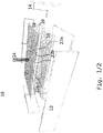
- Fig. 1 schematically shows a view of a mold 10 for a molding.
- the mold 10 has shuttering elements 12 to form a shuttering.
- the side shuttering elements can have holding devices in the form of hooks 14.
- the hooks 14 serve to hold or support a first optical waveguide mask 16 formed as a perforated plate on the assembled formwork.
- a corresponding hook construction (not shown) may be provided to hold a second optical fiber mask 18 also formed as a perforated plate.
- a tubular section 20 is provided in this example, which at least partially consists of the cladding and / or may protrude the later molding body and / or at least one opening to the defined by the pipe section 20 recording in the molded body offers.
- One end of a light guide 22 is in each case attached to a shuttering plate 12, in this example the ends are respectively inserted into the lower shuttering plate 12.
- the optical fiber bundle can then on the cast body a define a particularly compact radiation zone, which allows a simple irradiation of optical fibers, which are widely spaced on the radiating surface.
- a light guide 22b is shown, which is inserted from the outside or laterally between the optical fiber masks 16, 18 and clamped between them, and then to the pipe section 20 to be guided. It is also conceivable for a light guide 22b to be guided through one of the light guide masks 16 or 18 or looped through both light guide masks 16, 18 into the area between the masks 16, 18 in order to be clamped there and / or guided to the pipe section 20.
- the use of optical fiber masks a lateral redirection of optical fibers in a simple way possible.
- the light guide 22b can be guided to a radiation zone on any desired side and / or to a spray zone within the molded body. It goes without saying that it is also possible to guide a multiplicity of light guides 22b to the tube section 20, which bundles may be bundled and / or guided to an irradiation zone, which may be formed on a wall surface located in the tube section and / or in a corresponding receptacle within the molded body , In general, one end of the light guides 22 may be provided on each of the outer surfaces and / or the outer surfaces of the mold body corresponding shuttering panels 12 and passed through at least one optical fiber mask 16, 18 and / or passed and / or held.
- a light guide 22b is clamped between the optical fiber masks 16, 18 and thus is even held and guided by both masks.
- Both variants of the optical fiber guide can be present at the same time or can be used separately and / or repeatedly, for example in order to provide differently arranged spray zones, which can facilitate, for example, multi-colored lighting.
- the ends of the light guides 22 are first attached to a shuttering panel 12 as desired.
- the optical fiber masks 16, 18 are introduced into the casing, such as by means of the hooks 14; while the pipe section 20 can be arranged.
- the light guides 22 are either bundled by means of at least one of the light guide masks 16, 18 and guided upward in this example, or, by means of one or both light guide masks 16 or 18, laterally led to the pipe section 20 or to its intended location.
- the optical fiber masks 16, 18 are generally arranged or spaced so that they at least one between when filling casting material clamp them arranged light guide 22.
- the light guides 22 or bundle 24 are arranged as desired with respect to the shuttering to define at least one radiating zone.
- a molding material is filled in the mold 10 to flow around and cover the optical fiber masks 16, 18 and the optical fibers 22 and / or the pipe section 20. That molding material is cured, switched off and then reworked to produce about a desired surface finish and optionally remove unwanted protruding light guide sections and / or hook pieces.
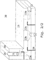
- Fig. 2 shows a schematic cross-sectional view of a molded body 30 with an angled shape.
- a first Lichttleitermaske 16 and a second optical fiber mask 18 are arranged, each having a shape corresponding to the molding body 30 corresponding bend.
- Luminous ends 23 of the light guides 22b can be seen on the surface of the molded body 30.
- the light guides 22b are each guided to receptacle 21, which may have been produced by means of pipe sections, as in Fig. 1 shown. Alternative casting methods can also be used.
- receptacles 21 each Anstrahlzonen are formed with light guide ends.
- a plurality of receptacles 21 are provided, in each of which different lighting devices or luminous bodies can be used. It can, for example, in different colors luminous luminous bodies are used.
Landscapes
- Engineering & Computer Science (AREA)
- Architecture (AREA)
- Civil Engineering (AREA)
- Structural Engineering (AREA)
- Manufacturing & Machinery (AREA)
- Chemical & Material Sciences (AREA)
- Ceramic Engineering (AREA)
- Mechanical Engineering (AREA)
- Non-Portable Lighting Devices Or Systems Thereof (AREA)
- Planar Illumination Modules (AREA)
- Optical Couplings Of Light Guides (AREA)
- Optical Fibers, Optical Fiber Cores, And Optical Fiber Bundles (AREA)
Priority Applications (1)
| Application Number | Priority Date | Filing Date | Title |
|---|---|---|---|
| PL15162181T PL2929995T3 (pl) | 2014-04-01 | 2015-04-01 | Odlew kształtowy wyposażony w światłowód |
Applications Claiming Priority (1)
| Application Number | Priority Date | Filing Date | Title |
|---|---|---|---|
| DE102014104593.9A DE102014104593A1 (de) | 2014-04-01 | 2014-04-01 | Formgussstück mit Lichtleiter |
Publications (2)
| Publication Number | Publication Date |
|---|---|
| EP2929995A1 EP2929995A1 (de) | 2015-10-14 |
| EP2929995B1 true EP2929995B1 (de) | 2017-09-06 |
Family
ID=53039696
Family Applications (1)
| Application Number | Title | Priority Date | Filing Date |
|---|---|---|---|
| EP15162181.0A Active EP2929995B1 (de) | 2014-04-01 | 2015-04-01 | Formgussstück mit lichtleiter |
Country Status (6)
| Country | Link |
|---|---|
| EP (1) | EP2929995B1 (pl) |
| DE (1) | DE102014104593A1 (pl) |
| DK (1) | DK2929995T3 (pl) |
| ES (1) | ES2650946T3 (pl) |
| NO (1) | NO3098553T3 (pl) |
| PL (1) | PL2929995T3 (pl) |
Families Citing this family (1)
| Publication number | Priority date | Publication date | Assignee | Title |
|---|---|---|---|---|
| CN113482236B (zh) * | 2021-06-10 | 2022-06-10 | 深圳文业装饰设计工程有限公司 | 一种透光型立体隔墙 |
Family Cites Families (9)
| Publication number | Priority date | Publication date | Assignee | Title |
|---|---|---|---|---|
| JP2511492Y2 (ja) * | 1990-02-02 | 1996-09-25 | 大阪瓦斯株式会社 | 装飾用板のファイバ―支持構造 |
| JPH04288203A (ja) * | 1991-01-21 | 1992-10-13 | Shimizu Corp | 光ファイバ付きコンクリート製品及びその製造方法 |
| JPH08166516A (ja) * | 1994-12-14 | 1996-06-25 | Mitsubishi Rayon Co Ltd | 埋設架台付き光ファイバユニット |
| DE29522298U1 (de) * | 1995-02-03 | 2001-06-21 | Rinn Beton- und Naturstein GmbH & Co. KG., 35452 Heuchelheim | Bauelement aus Kunststein |
| DE19504996A1 (de) * | 1995-02-15 | 1996-08-22 | Siegesmund Raeder | Verfahren zur Herstellung einer Leuchtanzeige-Vorrichtung und danach hergestellte Leuchtanzeigevorrichtung |
| DE102007013199A1 (de) * | 2007-03-15 | 2008-11-06 | Delunamagma Industries Gmbh | Verfahren und Vorrichtung zur Herstellung eines lichtdurchlässigen Mehrschicht-Verbund-Bauelementes für Fassaden |
| DE102007035878A1 (de) * | 2007-07-31 | 2009-02-26 | Rwth Aachen | Bauelement mit interner Leiteranordnung und Verfahren zu dessen Herstellung |
| DE102008003016A1 (de) * | 2008-01-02 | 2009-07-16 | Fabrizio Francia | Bauplatte mit Illuminations- bzw. Leuchtelementen und Verfahren zu deren Herstellung |
| DE102011114126A1 (de) * | 2011-09-23 | 2013-03-28 | Frank Gartzke | Verfahren und Vorrichtung zum Herstellen eines Formkörpers mit Lichtleitern sowie Formkörper aus einer härtbaren oder aushärtenden gießfähigen Masse |
-
2014
- 2014-04-01 DE DE102014104593.9A patent/DE102014104593A1/de not_active Ceased
-
2015
- 2015-04-01 PL PL15162181T patent/PL2929995T3/pl unknown
- 2015-04-01 DK DK15162181.0T patent/DK2929995T3/en active
- 2015-04-01 EP EP15162181.0A patent/EP2929995B1/de active Active
- 2015-04-01 ES ES15162181.0T patent/ES2650946T3/es active Active
-
2016
- 2016-05-19 NO NO16170441A patent/NO3098553T3/no unknown
Non-Patent Citations (1)
| Title |
|---|
| None * |
Also Published As
| Publication number | Publication date |
|---|---|
| ES2650946T3 (es) | 2018-01-23 |
| PL2929995T3 (pl) | 2018-02-28 |
| NO3098553T3 (pl) | 2018-02-10 |
| DK2929995T3 (en) | 2017-12-04 |
| EP2929995A1 (de) | 2015-10-14 |
| DE102014104593A1 (de) | 2015-10-01 |
Similar Documents
| Publication | Publication Date | Title |
|---|---|---|
| EP1970179B1 (de) | Verfahren zur Herstellung eines lichtdurchlässigen Mehrschicht-Verbund-Bauelementes für Fassaden und so hergestelltes Bauelement | |
| EP2665588A1 (de) | Licht leitendes bauteil für bauwerke und gebäude sowie herstellungsverfahren dafür | |
| DE20321524U1 (de) | Baustein mit lichtleitenden Fasern | |
| EP2180986B1 (de) | VORRICHTUNG UND VERFAHREN ZUR HERSTELLUNG eines lichtleitenden Bauelementes | |
| EP2559532B1 (de) | Verfahren zur Herstellung eines lichtdurchlässigen Mehrschicht-Verbundbauelementes mit integrierter Fassadenplatte, sowie mit diesem Verfahren hergestellte Produkte | |
| DE102019131051B4 (de) | Verfahren zur Herstellung eines bewehrten Betonbauteils, bewehrtes Betonbauteil und Fertigungssystem | |
| EP1943394A1 (de) | Baustein mit lichtdurchlässigen fasern | |
| DE19618368B4 (de) | Anordnung aus Fadenführungselementen einer Kettenwirk- oder Strickmaschine und einem Träger | |
| EP3424690B1 (de) | Verfahren und vorrichtung zur herstellung eines bewehrungsgitters | |
| DE10141243A1 (de) | Innenschale für ein Dachmodul in Sandwich-Bauweise sowie Verfahren zu ihrer Herstellung | |
| DE2028111C3 (de) | Verfahren zur Herstellung einer lichtabsorbierende Faserelemente enthaltenden, zur Bildübertragung dienenden Faserplatte | |
| EP2234120A2 (de) | Verfahren zum Herstellen eines Kabelbaums, Vorrichtung zum Aufgeben eines aushärtenden Materials und Kabelbaum | |
| EP2929995B1 (de) | Formgussstück mit lichtleiter | |
| EP3274621B1 (de) | Lichtleitkörper mit spritzgussmatte und lichtkanälen | |
| DE202011110213U1 (de) | Vorrichtung zum Herstellen eines Formkörpers mit Lichtleitern sowie Formkörper aus einer härtbaren oder aushärtbaren gießfähigen Masse | |
| WO2010028841A1 (de) | Verfahren und vorrichtung zur herstellung eines lichtleitenden baukörpers | |
| WO2009016151A1 (de) | Bauelement mit interner leiteranordnung und verfahren zu dessen herstellung | |
| WO2008119670A1 (de) | Bauelement mit funktionellen fasern und verfahren zu dessen herstellung | |
| EP0595171B1 (de) | Armierungsgewebe für Putze, Dämmsysteme, Estriche oder dgl. | |
| DE4004474A1 (de) | Verfahren zur herstellung von verbundbauteilen | |
| DE19504996A1 (de) | Verfahren zur Herstellung einer Leuchtanzeige-Vorrichtung und danach hergestellte Leuchtanzeigevorrichtung | |
| EP2604767A1 (de) | Lichtdurchlässiger Verbundkörper mit kugelförmigen Lichtleitkörpern, sowie Verfahren zur Herstellung eines lichtdurchlässigen Verbundkörpers | |
| DE19719049C1 (de) | Verfahren zur Herstellung textilbewehrter Bauelemente bzw. Verstärkungsschichten für Bauelemente | |
| DE3152924C2 (en) | Moulding box for the production of a ceramic mould | |
| WO2021069364A1 (de) | Bauelement mit stromschienensystem und gebäude mit bauelement sowie verfahren zur herstellung eines bauelements |
Legal Events
| Date | Code | Title | Description |
|---|---|---|---|
| PUAI | Public reference made under article 153(3) epc to a published international application that has entered the european phase |
Free format text: ORIGINAL CODE: 0009012 |
|
| AK | Designated contracting states |
Kind code of ref document: A1 Designated state(s): AL AT BE BG CH CY CZ DE DK EE ES FI FR GB GR HR HU IE IS IT LI LT LU LV MC MK MT NL NO PL PT RO RS SE SI SK SM TR |
|
| AX | Request for extension of the european patent |
Extension state: BA ME |
|
| 17P | Request for examination filed |
Effective date: 20160411 |
|
| RBV | Designated contracting states (corrected) |
Designated state(s): AL AT BE BG CH CY CZ DE DK EE ES FI FR GB GR HR HU IE IS IT LI LT LU LV MC MK MT NL NO PL PT RO RS SE SI SK SM TR |
|
| RAP1 | Party data changed (applicant data changed or rights of an application transferred) |
Owner name: SIUT GMBH |
|
| RIN1 | Information on inventor provided before grant (corrected) |
Inventor name: GENZ, VINCENT Inventor name: WESTERHEIDE, BENJAMIN |
|
| TPAC | Observations filed by third parties |
Free format text: ORIGINAL CODE: EPIDOSNTIPA |
|
| 17Q | First examination report despatched |
Effective date: 20170206 |
|
| TPAC | Observations filed by third parties |
Free format text: ORIGINAL CODE: EPIDOSNTIPA |
|
| GRAP | Despatch of communication of intention to grant a patent |
Free format text: ORIGINAL CODE: EPIDOSNIGR1 |
|
| RIC1 | Information provided on ipc code assigned before grant |
Ipc: B28B 23/00 20060101AFI20170522BHEP Ipc: E04C 2/54 20060101ALI20170522BHEP Ipc: E04C 1/42 20060101ALI20170522BHEP Ipc: E04C 2/04 20060101ALI20170522BHEP |
|
| INTG | Intention to grant announced |
Effective date: 20170612 |
|
| RAP3 | Party data changed (applicant data changed or rights of an application transferred) |
Owner name: SIUT GMBH |
|
| GRAS | Grant fee paid |
Free format text: ORIGINAL CODE: EPIDOSNIGR3 |
|
| GRAA | (expected) grant |
Free format text: ORIGINAL CODE: 0009210 |
|
| AK | Designated contracting states |
Kind code of ref document: B1 Designated state(s): AL AT BE BG CH CY CZ DE DK EE ES FI FR GB GR HR HU IE IS IT LI LT LU LV MC MK MT NL NO PL PT RO RS SE SI SK SM TR |
|
| REG | Reference to a national code |
Ref country code: GB Ref legal event code: FG4D Free format text: NOT ENGLISH |
|
| REG | Reference to a national code |
Ref country code: CH Ref legal event code: EP Ref country code: AT Ref legal event code: REF Ref document number: 925374 Country of ref document: AT Kind code of ref document: T Effective date: 20170915 |
|
| REG | Reference to a national code |
Ref country code: IE Ref legal event code: FG4D Free format text: LANGUAGE OF EP DOCUMENT: GERMAN |
|
| REG | Reference to a national code |
Ref country code: DE Ref legal event code: R096 Ref document number: 502015001815 Country of ref document: DE |
|
| REG | Reference to a national code |
Ref country code: CH Ref legal event code: NV Representative=s name: ANDRE ROLAND S.A., CH |
|
| REG | Reference to a national code |
Ref country code: DK Ref legal event code: T3 Effective date: 20171128 |
|
| REG | Reference to a national code |
Ref country code: SE Ref legal event code: TRGR |
|
| REG | Reference to a national code |
Ref country code: NL Ref legal event code: FP |
|
| REG | Reference to a national code |
Ref country code: ES Ref legal event code: FG2A Ref document number: 2650946 Country of ref document: ES Kind code of ref document: T3 Effective date: 20180123 |
|
| REG | Reference to a national code |
Ref country code: LT Ref legal event code: MG4D |
|
| PG25 | Lapsed in a contracting state [announced via postgrant information from national office to epo] |
Ref country code: LT Free format text: LAPSE BECAUSE OF FAILURE TO SUBMIT A TRANSLATION OF THE DESCRIPTION OR TO PAY THE FEE WITHIN THE PRESCRIBED TIME-LIMIT Effective date: 20170906 Ref country code: HR Free format text: LAPSE BECAUSE OF FAILURE TO SUBMIT A TRANSLATION OF THE DESCRIPTION OR TO PAY THE FEE WITHIN THE PRESCRIBED TIME-LIMIT Effective date: 20170906 |
|
| REG | Reference to a national code |
Ref country code: NO Ref legal event code: T2 Effective date: 20170906 |
|
| PG25 | Lapsed in a contracting state [announced via postgrant information from national office to epo] |
Ref country code: BG Free format text: LAPSE BECAUSE OF FAILURE TO SUBMIT A TRANSLATION OF THE DESCRIPTION OR TO PAY THE FEE WITHIN THE PRESCRIBED TIME-LIMIT Effective date: 20171206 Ref country code: LV Free format text: LAPSE BECAUSE OF FAILURE TO SUBMIT A TRANSLATION OF THE DESCRIPTION OR TO PAY THE FEE WITHIN THE PRESCRIBED TIME-LIMIT Effective date: 20170906 Ref country code: GR Free format text: LAPSE BECAUSE OF FAILURE TO SUBMIT A TRANSLATION OF THE DESCRIPTION OR TO PAY THE FEE WITHIN THE PRESCRIBED TIME-LIMIT Effective date: 20171207 Ref country code: RS Free format text: LAPSE BECAUSE OF FAILURE TO SUBMIT A TRANSLATION OF THE DESCRIPTION OR TO PAY THE FEE WITHIN THE PRESCRIBED TIME-LIMIT Effective date: 20170906 |
|
| REG | Reference to a national code |
Ref country code: FR Ref legal event code: PLFP Year of fee payment: 4 |
|
| PG25 | Lapsed in a contracting state [announced via postgrant information from national office to epo] |
Ref country code: RO Free format text: LAPSE BECAUSE OF FAILURE TO SUBMIT A TRANSLATION OF THE DESCRIPTION OR TO PAY THE FEE WITHIN THE PRESCRIBED TIME-LIMIT Effective date: 20170906 |
|
| PG25 | Lapsed in a contracting state [announced via postgrant information from national office to epo] |
Ref country code: EE Free format text: LAPSE BECAUSE OF FAILURE TO SUBMIT A TRANSLATION OF THE DESCRIPTION OR TO PAY THE FEE WITHIN THE PRESCRIBED TIME-LIMIT Effective date: 20170906 Ref country code: SK Free format text: LAPSE BECAUSE OF FAILURE TO SUBMIT A TRANSLATION OF THE DESCRIPTION OR TO PAY THE FEE WITHIN THE PRESCRIBED TIME-LIMIT Effective date: 20170906 Ref country code: IS Free format text: LAPSE BECAUSE OF FAILURE TO SUBMIT A TRANSLATION OF THE DESCRIPTION OR TO PAY THE FEE WITHIN THE PRESCRIBED TIME-LIMIT Effective date: 20180106 Ref country code: SM Free format text: LAPSE BECAUSE OF FAILURE TO SUBMIT A TRANSLATION OF THE DESCRIPTION OR TO PAY THE FEE WITHIN THE PRESCRIBED TIME-LIMIT Effective date: 20170906 |
|
| REG | Reference to a national code |
Ref country code: DE Ref legal event code: R097 Ref document number: 502015001815 Country of ref document: DE |
|
| PLBE | No opposition filed within time limit |
Free format text: ORIGINAL CODE: 0009261 |
|
| STAA | Information on the status of an ep patent application or granted ep patent |
Free format text: STATUS: NO OPPOSITION FILED WITHIN TIME LIMIT |
|
| 26N | No opposition filed |
Effective date: 20180607 |
|
| PG25 | Lapsed in a contracting state [announced via postgrant information from national office to epo] |
Ref country code: SI Free format text: LAPSE BECAUSE OF FAILURE TO SUBMIT A TRANSLATION OF THE DESCRIPTION OR TO PAY THE FEE WITHIN THE PRESCRIBED TIME-LIMIT Effective date: 20170906 |
|
| PG25 | Lapsed in a contracting state [announced via postgrant information from national office to epo] |
Ref country code: MT Free format text: LAPSE BECAUSE OF FAILURE TO SUBMIT A TRANSLATION OF THE DESCRIPTION OR TO PAY THE FEE WITHIN THE PRESCRIBED TIME-LIMIT Effective date: 20170906 |
|
| PG25 | Lapsed in a contracting state [announced via postgrant information from national office to epo] |
Ref country code: MC Free format text: LAPSE BECAUSE OF FAILURE TO SUBMIT A TRANSLATION OF THE DESCRIPTION OR TO PAY THE FEE WITHIN THE PRESCRIBED TIME-LIMIT Effective date: 20170906 |
|
| REG | Reference to a national code |
Ref country code: BE Ref legal event code: MM Effective date: 20180430 |
|
| REG | Reference to a national code |
Ref country code: IE Ref legal event code: MM4A |
|
| REG | Reference to a national code |
Ref country code: DE Ref legal event code: R082 Ref document number: 502015001815 Country of ref document: DE Representative=s name: ETL IP PATENTANWALTSGESELLSCHAFT MBH, DE Ref country code: DE Ref legal event code: R082 Ref document number: 502015001815 Country of ref document: DE Representative=s name: ETL IP PATENT- UND RECHTSANWALTSGESELLSCHAFT M, DE Ref country code: DE Ref legal event code: R082 Ref document number: 502015001815 Country of ref document: DE Representative=s name: ETL WABLAT & KOLLEGEN PATENT- UND RECHTSANWALT, DE |
|
| PG25 | Lapsed in a contracting state [announced via postgrant information from national office to epo] |
Ref country code: LU Free format text: LAPSE BECAUSE OF NON-PAYMENT OF DUE FEES Effective date: 20180401 |
|
| PG25 | Lapsed in a contracting state [announced via postgrant information from national office to epo] |
Ref country code: BE Free format text: LAPSE BECAUSE OF NON-PAYMENT OF DUE FEES Effective date: 20180430 |
|
| PG25 | Lapsed in a contracting state [announced via postgrant information from national office to epo] |
Ref country code: IE Free format text: LAPSE BECAUSE OF NON-PAYMENT OF DUE FEES Effective date: 20180401 |
|
| PG25 | Lapsed in a contracting state [announced via postgrant information from national office to epo] |
Ref country code: TR Free format text: LAPSE BECAUSE OF FAILURE TO SUBMIT A TRANSLATION OF THE DESCRIPTION OR TO PAY THE FEE WITHIN THE PRESCRIBED TIME-LIMIT Effective date: 20170906 |
|
| PG25 | Lapsed in a contracting state [announced via postgrant information from national office to epo] |
Ref country code: PT Free format text: LAPSE BECAUSE OF FAILURE TO SUBMIT A TRANSLATION OF THE DESCRIPTION OR TO PAY THE FEE WITHIN THE PRESCRIBED TIME-LIMIT Effective date: 20170906 |
|
| PG25 | Lapsed in a contracting state [announced via postgrant information from national office to epo] |
Ref country code: MK Free format text: LAPSE BECAUSE OF NON-PAYMENT OF DUE FEES Effective date: 20170906 Ref country code: HU Free format text: LAPSE BECAUSE OF FAILURE TO SUBMIT A TRANSLATION OF THE DESCRIPTION OR TO PAY THE FEE WITHIN THE PRESCRIBED TIME-LIMIT; INVALID AB INITIO Effective date: 20150401 Ref country code: CY Free format text: LAPSE BECAUSE OF FAILURE TO SUBMIT A TRANSLATION OF THE DESCRIPTION OR TO PAY THE FEE WITHIN THE PRESCRIBED TIME-LIMIT Effective date: 20170906 |
|
| REG | Reference to a national code |
Ref country code: DE Ref legal event code: R082 Ref document number: 502015001815 Country of ref document: DE Representative=s name: ETL IP PATENTANWALTSGESELLSCHAFT MBH, DE Ref country code: DE Ref legal event code: R082 Ref document number: 502015001815 Country of ref document: DE Representative=s name: ETL IP PATENT- UND RECHTSANWALTSGESELLSCHAFT M, DE |
|
| PG25 | Lapsed in a contracting state [announced via postgrant information from national office to epo] |
Ref country code: AL Free format text: LAPSE BECAUSE OF FAILURE TO SUBMIT A TRANSLATION OF THE DESCRIPTION OR TO PAY THE FEE WITHIN THE PRESCRIBED TIME-LIMIT Effective date: 20170906 |
|
| PGFP | Annual fee paid to national office [announced via postgrant information from national office to epo] |
Ref country code: CZ Payment date: 20240327 Year of fee payment: 10 |
|
| PGFP | Annual fee paid to national office [announced via postgrant information from national office to epo] |
Ref country code: NL Payment date: 20240422 Year of fee payment: 10 |
|
| PGFP | Annual fee paid to national office [announced via postgrant information from national office to epo] |
Ref country code: PL Payment date: 20240325 Year of fee payment: 10 |
|
| PGFP | Annual fee paid to national office [announced via postgrant information from national office to epo] |
Ref country code: GB Payment date: 20240423 Year of fee payment: 10 |
|
| PGFP | Annual fee paid to national office [announced via postgrant information from national office to epo] |
Ref country code: CH Payment date: 20240501 Year of fee payment: 10 |
|
| PGFP | Annual fee paid to national office [announced via postgrant information from national office to epo] |
Ref country code: ES Payment date: 20240517 Year of fee payment: 10 |
|
| PGFP | Annual fee paid to national office [announced via postgrant information from national office to epo] |
Ref country code: AT Payment date: 20240417 Year of fee payment: 10 |
|
| PGFP | Annual fee paid to national office [announced via postgrant information from national office to epo] |
Ref country code: NO Payment date: 20240419 Year of fee payment: 10 Ref country code: IT Payment date: 20240430 Year of fee payment: 10 Ref country code: FR Payment date: 20240423 Year of fee payment: 10 Ref country code: FI Payment date: 20240418 Year of fee payment: 10 |
|
| PGFP | Annual fee paid to national office [announced via postgrant information from national office to epo] |
Ref country code: SE Payment date: 20240423 Year of fee payment: 10 |
|
| PGFP | Annual fee paid to national office [announced via postgrant information from national office to epo] |
Ref country code: DE Payment date: 20250317 Year of fee payment: 11 |
|
| PGFP | Annual fee paid to national office [announced via postgrant information from national office to epo] |
Ref country code: DK Payment date: 20250423 Year of fee payment: 11 |
|
| PG25 | Lapsed in a contracting state [announced via postgrant information from national office to epo] |
Ref country code: CZ Free format text: LAPSE BECAUSE OF NON-PAYMENT OF DUE FEES Effective date: 20250401 |
|
| REG | Reference to a national code |
Ref country code: CH Ref legal event code: H13 Free format text: ST27 STATUS EVENT CODE: U-0-0-H10-H13 (AS PROVIDED BY THE NATIONAL OFFICE) Effective date: 20251125 |
|
| REG | Reference to a national code |
Ref country code: SE Ref legal event code: EUG |
|
| REG | Reference to a national code |
Ref country code: NL Ref legal event code: MM Effective date: 20250501 |
|
| REG | Reference to a national code |
Ref country code: AT Ref legal event code: MM01 Ref document number: 925374 Country of ref document: AT Kind code of ref document: T Effective date: 20250401 |
|
| GBPC | Gb: european patent ceased through non-payment of renewal fee |
Effective date: 20250401 |
|
| PG25 | Lapsed in a contracting state [announced via postgrant information from national office to epo] |
Ref country code: GB Free format text: LAPSE BECAUSE OF NON-PAYMENT OF DUE FEES Effective date: 20250401 |
|
| PG25 | Lapsed in a contracting state [announced via postgrant information from national office to epo] |
Ref country code: NO Free format text: LAPSE BECAUSE OF NON-PAYMENT OF DUE FEES Effective date: 20250430 |
|
| PG25 | Lapsed in a contracting state [announced via postgrant information from national office to epo] |
Ref country code: AT Free format text: LAPSE BECAUSE OF NON-PAYMENT OF DUE FEES Effective date: 20250401 |
|
| PG25 | Lapsed in a contracting state [announced via postgrant information from national office to epo] |
Ref country code: FI Free format text: LAPSE BECAUSE OF NON-PAYMENT OF DUE FEES Effective date: 20250401 |
|
| PG25 | Lapsed in a contracting state [announced via postgrant information from national office to epo] |
Ref country code: NL Free format text: LAPSE BECAUSE OF NON-PAYMENT OF DUE FEES Effective date: 20250501 Ref country code: FR Free format text: LAPSE BECAUSE OF NON-PAYMENT OF DUE FEES Effective date: 20250430 |
|
| PG25 | Lapsed in a contracting state [announced via postgrant information from national office to epo] |
Ref country code: CH Free format text: LAPSE BECAUSE OF NON-PAYMENT OF DUE FEES Effective date: 20250430 |
|
| PG25 | Lapsed in a contracting state [announced via postgrant information from national office to epo] |
Ref country code: SE Free format text: LAPSE BECAUSE OF NON-PAYMENT OF DUE FEES Effective date: 20250402 |
|
| PG25 | Lapsed in a contracting state [announced via postgrant information from national office to epo] |
Ref country code: IT Free format text: LAPSE BECAUSE OF NON-PAYMENT OF DUE FEES Effective date: 20250401 |