EP2930117A1 - Dispositif et procédé de fabrication de gerbes d'articles collées les uns aux autres à l'aide d'un adhésif - Google Patents
Dispositif et procédé de fabrication de gerbes d'articles collées les uns aux autres à l'aide d'un adhésif Download PDFInfo
- Publication number
- EP2930117A1 EP2930117A1 EP15159222.7A EP15159222A EP2930117A1 EP 2930117 A1 EP2930117 A1 EP 2930117A1 EP 15159222 A EP15159222 A EP 15159222A EP 2930117 A1 EP2930117 A1 EP 2930117A1
- Authority
- EP
- European Patent Office
- Prior art keywords
- articles
- adhesive
- splices
- container
- article
- Prior art date
- Legal status (The legal status is an assumption and is not a legal conclusion. Google has not performed a legal analysis and makes no representation as to the accuracy of the status listed.)
- Granted
Links
Images


Classifications
-
- B—PERFORMING OPERATIONS; TRANSPORTING
- B65—CONVEYING; PACKING; STORING; HANDLING THIN OR FILAMENTARY MATERIAL
- B65B—MACHINES, APPARATUS OR DEVICES FOR, OR METHODS OF, PACKAGING ARTICLES OR MATERIALS; UNPACKING
- B65B17/00—Other machines, apparatus, or methods for packaging articles or materials
- B65B17/02—Joining articles, e.g. cans, directly to each other for convenience of storage, transport, or handling
-
- B—PERFORMING OPERATIONS; TRANSPORTING
- B65—CONVEYING; PACKING; STORING; HANDLING THIN OR FILAMENTARY MATERIAL
- B65B—MACHINES, APPARATUS OR DEVICES FOR, OR METHODS OF, PACKAGING ARTICLES OR MATERIALS; UNPACKING
- B65B27/00—Bundling particular articles presenting special problems using string, wire, or narrow tape or band; Baling fibrous material, e.g. peat, not otherwise provided for
- B65B27/04—Bundling groups of cans or bottles
-
- B—PERFORMING OPERATIONS; TRANSPORTING
- B65—CONVEYING; PACKING; STORING; HANDLING THIN OR FILAMENTARY MATERIAL
- B65B—MACHINES, APPARATUS OR DEVICES FOR, OR METHODS OF, PACKAGING ARTICLES OR MATERIALS; UNPACKING
- B65B35/00—Supplying, feeding, arranging or orientating articles to be packaged
- B65B35/30—Arranging and feeding articles in groups
- B65B35/44—Arranging and feeding articles in groups by endless belts or chains
-
- B—PERFORMING OPERATIONS; TRANSPORTING
- B65—CONVEYING; PACKING; STORING; HANDLING THIN OR FILAMENTARY MATERIAL
- B65B—MACHINES, APPARATUS OR DEVICES FOR, OR METHODS OF, PACKAGING ARTICLES OR MATERIALS; UNPACKING
- B65B35/00—Supplying, feeding, arranging or orientating articles to be packaged
- B65B35/30—Arranging and feeding articles in groups
- B65B35/54—Feeding articles along multiple paths to a single packaging position
-
- B—PERFORMING OPERATIONS; TRANSPORTING
- B65—CONVEYING; PACKING; STORING; HANDLING THIN OR FILAMENTARY MATERIAL
- B65B—MACHINES, APPARATUS OR DEVICES FOR, OR METHODS OF, PACKAGING ARTICLES OR MATERIALS; UNPACKING
- B65B63/00—Auxiliary devices, not otherwise provided for, for operating on articles or materials to be packaged
- B65B63/08—Auxiliary devices, not otherwise provided for, for operating on articles or materials to be packaged for heating or cooling articles or materials to facilitate packaging
-
- C—CHEMISTRY; METALLURGY
- C04—CEMENTS; CONCRETE; ARTIFICIAL STONE; CERAMICS; REFRACTORIES
- C04B—LIME, MAGNESIA; SLAG; CEMENTS; COMPOSITIONS THEREOF, e.g. MORTARS, CONCRETE OR LIKE BUILDING MATERIALS; ARTIFICIAL STONE; CERAMICS; REFRACTORIES; TREATMENT OF NATURAL STONE
- C04B16/00—Use of organic materials as fillers, e.g. pigments, for mortars, concrete or artificial stone; Treatment of organic materials specially adapted to enhance their filling properties in mortars, concrete or artificial stone
- C04B16/02—Cellulosic materials
-
- C—CHEMISTRY; METALLURGY
- C04—CEMENTS; CONCRETE; ARTIFICIAL STONE; CERAMICS; REFRACTORIES
- C04B—LIME, MAGNESIA; SLAG; CEMENTS; COMPOSITIONS THEREOF, e.g. MORTARS, CONCRETE OR LIKE BUILDING MATERIALS; ARTIFICIAL STONE; CERAMICS; REFRACTORIES; TREATMENT OF NATURAL STONE
- C04B28/00—Compositions of mortars, concrete or artificial stone, containing inorganic binders or the reaction product of an inorganic and an organic binder, e.g. polycarboxylate cements
- C04B28/02—Compositions of mortars, concrete or artificial stone, containing inorganic binders or the reaction product of an inorganic and an organic binder, e.g. polycarboxylate cements containing hydraulic cements other than calcium sulfates
-
- E—FIXED CONSTRUCTIONS
- E04—BUILDING
- E04B—GENERAL BUILDING CONSTRUCTIONS; WALLS, e.g. PARTITIONS; ROOFS; FLOORS; CEILINGS; INSULATION OR OTHER PROTECTION OF BUILDINGS
- E04B1/00—Constructions in general; Structures which are not restricted either to walls, e.g. partitions, or floors or ceilings or roofs
- E04B1/348—Structures composed of units comprising at least considerable parts of two sides of a room, e.g. box-like or cell-like units closed or in skeleton form
-
- E—FIXED CONSTRUCTIONS
- E04—BUILDING
- E04B—GENERAL BUILDING CONSTRUCTIONS; WALLS, e.g. PARTITIONS; ROOFS; FLOORS; CEILINGS; INSULATION OR OTHER PROTECTION OF BUILDINGS
- E04B1/00—Constructions in general; Structures which are not restricted either to walls, e.g. partitions, or floors or ceilings or roofs
- E04B1/348—Structures composed of units comprising at least considerable parts of two sides of a room, e.g. box-like or cell-like units closed or in skeleton form
- E04B1/34815—Elements not integrated in a skeleton
- E04B1/3483—Elements not integrated in a skeleton the supporting structure consisting of metal
-
- E—FIXED CONSTRUCTIONS
- E04—BUILDING
- E04C—STRUCTURAL ELEMENTS; BUILDING MATERIALS
- E04C2/00—Building elements of relatively thin form for the construction of parts of buildings, e.g. sheet materials, slabs, or panels
- E04C2/02—Building elements of relatively thin form for the construction of parts of buildings, e.g. sheet materials, slabs, or panels characterised by specified materials
- E04C2/04—Building elements of relatively thin form for the construction of parts of buildings, e.g. sheet materials, slabs, or panels characterised by specified materials of concrete or other stone-like material; of asbestos cement; of cement and other mineral fibres
-
- E—FIXED CONSTRUCTIONS
- E04—BUILDING
- E04C—STRUCTURAL ELEMENTS; BUILDING MATERIALS
- E04C2/00—Building elements of relatively thin form for the construction of parts of buildings, e.g. sheet materials, slabs, or panels
- E04C2/02—Building elements of relatively thin form for the construction of parts of buildings, e.g. sheet materials, slabs, or panels characterised by specified materials
- E04C2/04—Building elements of relatively thin form for the construction of parts of buildings, e.g. sheet materials, slabs, or panels characterised by specified materials of concrete or other stone-like material; of asbestos cement; of cement and other mineral fibres
- E04C2/06—Building elements of relatively thin form for the construction of parts of buildings, e.g. sheet materials, slabs, or panels characterised by specified materials of concrete or other stone-like material; of asbestos cement; of cement and other mineral fibres reinforced
-
- E—FIXED CONSTRUCTIONS
- E04—BUILDING
- E04C—STRUCTURAL ELEMENTS; BUILDING MATERIALS
- E04C2/00—Building elements of relatively thin form for the construction of parts of buildings, e.g. sheet materials, slabs, or panels
- E04C2/02—Building elements of relatively thin form for the construction of parts of buildings, e.g. sheet materials, slabs, or panels characterised by specified materials
- E04C2/26—Building elements of relatively thin form for the construction of parts of buildings, e.g. sheet materials, slabs, or panels characterised by specified materials composed of materials covered by two or more of groups E04C2/04, E04C2/08, E04C2/10 or of materials covered by one of these groups with a material not specified in one of the groups
-
- B—PERFORMING OPERATIONS; TRANSPORTING
- B65—CONVEYING; PACKING; STORING; HANDLING THIN OR FILAMENTARY MATERIAL
- B65G—TRANSPORT OR STORAGE DEVICES, e.g. CONVEYORS FOR LOADING OR TIPPING, SHOP CONVEYOR SYSTEMS OR PNEUMATIC TUBE CONVEYORS
- B65G47/00—Article or material-handling devices associated with conveyors; Methods employing such devices
- B65G47/52—Devices for transferring articles or materials between conveyors i.e. discharging or feeding devices
- B65G47/68—Devices for transferring articles or materials between conveyors i.e. discharging or feeding devices adapted to receive articles arriving in one layer from one conveyor lane and to transfer them in individual layers to more than one conveyor lane or to one broader conveyor lane, or vice versa, e.g. combining the flows of articles conveyed by more than one conveyor
- B65G47/681—Devices for transferring articles or materials between conveyors i.e. discharging or feeding devices adapted to receive articles arriving in one layer from one conveyor lane and to transfer them in individual layers to more than one conveyor lane or to one broader conveyor lane, or vice versa, e.g. combining the flows of articles conveyed by more than one conveyor from distinct, separate conveyor lanes
-
- E—FIXED CONSTRUCTIONS
- E04—BUILDING
- E04C—STRUCTURAL ELEMENTS; BUILDING MATERIALS
- E04C2/00—Building elements of relatively thin form for the construction of parts of buildings, e.g. sheet materials, slabs, or panels
- E04C2002/001—Mechanical features of panels
- E04C2002/002—Panels with integrated lifting means, e.g. with hoisting lugs
-
- E—FIXED CONSTRUCTIONS
- E04—BUILDING
- E04H—BUILDINGS OR LIKE STRUCTURES FOR PARTICULAR PURPOSES; SWIMMING OR SPLASH BATHS OR POOLS; MASTS; FENCING; TENTS OR CANOPIES, IN GENERAL
- E04H1/00—Buildings or groups of buildings for dwelling or office purposes; General layout, e.g. modular co-ordination or staggered storeys
- E04H1/12—Small buildings or other erections for limited occupation, erected in the open air or arranged in buildings, e.g. kiosks, waiting shelters for bus stops or for filling stations, roofs for railway platforms, watchmen's huts or dressing cubicles
- E04H2001/1283—Small buildings of the ISO containers type
-
- Y—GENERAL TAGGING OF NEW TECHNOLOGICAL DEVELOPMENTS; GENERAL TAGGING OF CROSS-SECTIONAL TECHNOLOGIES SPANNING OVER SEVERAL SECTIONS OF THE IPC; TECHNICAL SUBJECTS COVERED BY FORMER USPC CROSS-REFERENCE ART COLLECTIONS [XRACs] AND DIGESTS
- Y02—TECHNOLOGIES OR APPLICATIONS FOR MITIGATION OR ADAPTATION AGAINST CLIMATE CHANGE
- Y02W—CLIMATE CHANGE MITIGATION TECHNOLOGIES RELATED TO WASTEWATER TREATMENT OR WASTE MANAGEMENT
- Y02W30/00—Technologies for solid waste management
- Y02W30/50—Reuse, recycling or recovery technologies
- Y02W30/91—Use of waste materials as fillers for mortars or concrete
Definitions
- the present invention relates to a device for producing containers made of articles bonded together by an adhesive according to the features of the preamble of claim 1 and to a method for producing containers of articles adhesively bonded together by an adhesive according to the features of the preamble of claim 12.
- PET polyethylene terephthalate
- Each article of a bundle of several articles has a footprint serving as footprint of the article, a cover surface spaced from the base surface by the normal height of the article, and a lateral surface connecting the circumference of the footprint to the circumference of the top surface.
- abutting surfaces in the finished container are generally parts of the lateral surfaces which, in comparison with remaining parts of the lateral surfaces, are the greatest distance from a central axis extending from the center of gravity of the base surface to the center of gravity of the upper surface, along which the centers of gravity of all successive ones , parallel to the base of extending cross-sectional areas of an article, have.
- the in the finished container abutting surfaces of the article comprising parts of the outer surfaces of the articles are provided with the adhesive by this point or line is applied before then the articles grouped according to their arrangement in the finished container and pressed together, at least for a short residence time be, for example, until one Curing adhesive requires an adhesive bond between the articles has been produced, which withstands a load in the further handling of the container or with a previously completed part of the container.
- a disadvantage which results in the production of a described, due to the adhesives produced by adhesive means also known as adhesive container resulting disadvantage is that the adhesion of the adhesive to the abutting in the finished container surfaces of the articles strongly depends on the state of these surfaces, while this with the Be provided adhesive.
- the cause of soiled and / or damp and / or wet jacket surfaces may be, for example, a cleaning or floor cooling or a so-called rinsing process, in which internal cleaning up to internal sterilization of articles to be filled with an ingredient takes place prior to their filling , or condensation of air humidity on colder surfaces of articles or a combination thereof, the enumeration not claiming to be exhaustive.
- DE 23 31 193 is a container of arranged at right angles to each other rows and rows arranged articles whose articles are connected by an adhesive directly to each other.
- the items may be cans or bottles.
- the cans have a cylindrical shape.
- the bottles are partially formed cylindrical and frustoconical.
- the adhesive may comprise an adhesive or an adhesive strip.
- the adhesive may be applied in the region of a cylindrical portion of an article over its entire circumference or over its entire height.
- the articles are PET containers.
- the container may be provided with a casing which surrounds the articles of the container on its periphery.
- the enclosure has at least one strapping.
- DE 10 2011 106 759 B3 describes a method for producing containers from articles provided with an adhesive, which are directly connected to one another.
- the articles may have tapers in comparison to the parts of the outer surfaces of the articles which comprise the surfaces of the articles which abut each other in the finished container.
- an enclosure enclosing the articles of the container on its periphery may run from a transparent material.
- the object of the invention is to provide an improved apparatus for the production of containers from each other by an adhesive agent adhered articles according to the features of the preamble of claim 1 and an improved process for the production of containers from each other by an adhesive agent bonded articles in which at least the respect Prior art mentioned disadvantage does not occur.
- a first subject of the invention accordingly relates to a device for the production of containers from articles joined together by an adhesive.
- the articles of the container are connected to one another by an adhesive, for example by means of one or more adhesives on areas of base and top surfaces of the articles, which are also referred to as splices, and which encompass peripheral surfaces or surfaces encompassed by them.
- the articles in the finished container at least approximately, for example, only the adhesive from each other spaced apart.
- Adhesive which is in particular arranged directly in front of a device with which at least a part of the totality of the splices of articles to be joined to a container to be joined together with adhesive.
- the drying device can be operated sensor-controlled with regard to their duration of action on the individual articles and / or with regard to the intensity of their action on the individual articles.
- the device comprises at least one sensor arranged in the region of the drying device for detecting moisture and / or moisture at least at the adhesion points to be provided at least in part with adhesive in relation to their entirety. In this way, it can be determined whether the splices and / or the surfaces of the articles to be joined together by an adhesive to a container are moist and / or wet and, for example, to save energy, the drying device is operated only if it was determined that the splices and / or or the surfaces of the articles to be joined together by an adhesive to a container are moist and / or wet.
- the senor may comprise a camera and / or be comprised of one with which it can be detected on the optical path-in particular via an image evaluation software-whether or not drops have formed at the points.
- This method is particularly suitable for detecting spatters on the articles resulting from a rinsing process or cooling.
- Another way of detecting moisture on the articles is to measure the humidity of the ambient air near the article transport path.
- a temperature of an ingredient or product that fills the articles, or the temperature at the surface the article, the transport speed and / or the time it takes the articles from a device for filling, for example a filling machine for adhesive application can be determined whether condensate may have formed on the surface. This can be determined for example by experiments.
- such alternative options relate to variants in which certain influencing factors are always constant - for example in an air-conditioned filling hall.
- the sensor has output signals which at least in the presence and / or the absence of moisture and / or moisture at least in Area of the splices of proportional to a container by means of adhesive to be connected to each other article are proportional.
- the device may comprise a control device connected to the drying device, which may be connected to the at least one sensor, but at least receives its output signals, and depending on the output signals, the duration of action and / or the intensity of the action of at least parts of the drying device on the individual article controls.
- the drying device can dry not only the parts comprising the splices, but alternatively the entire lateral surfaces of the means of adhesive to a container with each other to be joined articles and / or by their lateral surfaces and their base and / or top surfaces formed surfaces of the article.
- this may be advantageous, among other things, for example, in the processing of reusable articles, such as for removing old adhesive residues.
- the drying device may comprise at least one device for cleaning at least the entirety thereof be preceded in part with adhesives to be provided splices of the article, which may be part of the device.
- the drying device may comprise means for producing articles, for example a stretch blower for manufacturing to be preceded by articles to be filled with an ingredient, designed as containers, which may be part of the device.
- the device for producing articles may be followed by a device for filling the previously produced articles, which may be part of the device, and which in turn is disposed in front of the transport path of the drying device.
- the device for filling the articles previously produced With respect to a transport path of the articles from the drying device to the device, with which at least a part of the totality of the splices of articles to be joined to a container are provided with adhesive, the device for filling the articles previously produced, a device for closing the previously filled article, for example, by means of a respective cover to be arranged downstream, which may be part of the device, and which in turn is upstream with respect to the transport path of the drying device.
- the drying device can be a device for internal cleaning up to an internal sterilization of with a Ingredient to be filled, designed as a container items be pre-loaded before filling, which may be part of the device.
- a transport path of the articles from the drying device to the device with which at least a part of the totality of the splices of articles to be joined to a container are provided with adhesive
- Container designed articles designed means for the production of articles downstream of a device for cooling at least the base surfaces of the article, which in turn is upstream in relation to the transport path of the drying device and an optionally provided means for filling the previously manufactured article.
- this device for cooling at least the base surfaces of the article may be part of the device. Since there is a relatively large amount of material in the area of the base area in the case of PET bottles, which may still be relatively warm after production, this area is specifically cooled in order to avoid bulges that possibly arise during filling with the ingredient due to the filling pressure.
- the floor cooling can be done by spraying and / or sprinkling at least the base areas with water.
- the floor cooling can be like in EP 2 000 285 A2 be provided, the content of which is part of this application. Accordingly, at least at times a jet of water is directed to the bottom area of articles exported as PET bottles. Also conceivable are nozzles which atomize the cooling liquid or an immersion bath through which the bottoms of the articles designed as bottles are moved.
- the drying device may comprise a device for separating the transported along the transport path and to a Container to be joined together by means of an adhesive to be connected by separating articles article by article of one or more streams of articles each directly behind the other propagated articles be.
- the device for separating can also be part of the device.
- the articles are transported one after the other and more preferably in one lane, at least in the region of the drying device.
- a resulting advantage is that thereby all surfaces of the article are freely accessible.
- the containers grow successively, whereby initially parts of the finished container are produced by connecting a plurality of articles by means of adhesive, which parts are then connected to the finished container by means of adhesive.
- a drying device for splices of such already formed from several interconnected by adhesive articles formed parts of a container can be provided.
- the device With regard to a transport path of the articles from the drying device to the device, with which at least a part of the totality of the splices of articles to be joined to a container are provided with adhesive, the device with which at least a part of the totality of the splices of a means for merging and compressing of articles at their with respect to the entirety of their splices at least partially provided with adhesives splices according to their arrangement and orientation in the finished container to be arranged downstream of a container to be joined.
- the alignment is preferably carried out by maintaining and / or changing the orientation of individual and / or multiple articles in relation to their normal axes on their bases serving as footprints uprights.
- a maintenance and / or change of the orientation is preferably carried out by rotation of individual and / or several articles around their vertical axes.
- the compression is preferably carried out at least until a curing agent which requires a curing time has produced an adhesive bond between the articles which withstands a load during further handling of the container or a part of a container produced so far.
- Pressing in the context of the present invention is also understood to mean a slight pressing against each other so that the adhesive applied to one article touches at least the other container.
- the device for merging and compressing articles on their with respect to the entirety of their splices at least partially provided with adhesive splices can be arranged downstream of a palletizer with respect to a transport path of the article, which groups finished packages to stacking layers and at a stacking place to a stacking several stack layers existing stack.
- the device provides means, upstream of the drying device, for providing the adhesive means, with respect to a transport path of the articles from the drying device to the device, with which at least a part of the totality of the splices of articles to be joined to a container are provided with adhesive May include informational articles which may be part of the device.
- the information can be, for example, a design and / or a picture and / or a brand name and / or an indication of ingredients and / or nutritional values and / or a date of consumption and / or transport instructions and / or Hazard statements and / or storage instructions and / or processing instructions and / or instructions for use and / or address information, such as the manufacturing and / or packaging company and / or a commercial establishment, to show only some conceivable information.
- a typical example of a corresponding information carrier is a label, a band.
- a little common example in connection with food and beverage products, optionally in combination with a label, is an affixed so-called RFID tag comprising a transponder with an antenna, a transceiver consisting of an analogue circuit for receiving and Transmit, and has a digital circuit and at least one write-once and often readable, permanent memory.
- RFID radio-frequency identification
- transceiver systems for the automatic and contactless identification and localization of articles by means of radio waves. It facilitates the collection of data considerably.
- An RFID system consists of the RFID tag, which is located on or in the article and in the memory contains at least one identifying code, and a reader for reading this identifier.
- the coupling is done by generated by the reader electromagnetic alternating fields of short range or by high-frequency radio waves. This not only transmits data but also supplies the RFID tag with energy.
- Information can be stored directly readable in the memory of the RFID tag, or they can be stored on at least one server and / or in at least one database and identified by means of the stored in the memory of the RFID tag code and thereby associated with at least one article.
- a second way to provide articles with information is the so-called direct printing.
- the information is applied by printing technology one or more colors directly on the lateral surface. This may be the same information as can be visibly provided on one or more information carriers.
- one or more printing materials are applied to the surface of an article in one or more printing processes, depending on whether information is applied in a single or multiple print.
- a special form here are RFID tags, which can also be produced in direct printing via a special printing process of stable circuits made of polymers directly on the outer surface of articles.
- the articles may be filled with contents before being provided with information or subsequently, but before the adhesive is at least partially adhesive-coated.
- the drying device preferably comprises a heat introduction device which, for the removal of moisture and / or moisture at least at the splices on the surfaces of the articles to be joined by means of an adhesive into a container, promotes drying taking place, for example, by evaporation, as compared to one in the environment causes the device dormant article higher heat transfer at least at the splices and / or deposited on the splices moisture and / or moisture and ensures.
- a heat introduction device which, for the removal of moisture and / or moisture at least at the splices on the surfaces of the articles to be joined by means of an adhesive into a container, promotes drying taking place, for example, by evaporation, as compared to one in the environment causes the device dormant article higher heat transfer at least at the splices and / or deposited on the splices moisture and / or moisture and ensures.
- Heat transfer at least in the sense of the invention, involves thermal radiation, heat conduction and heat transfer from a solid surface to a fluid adjacent thereto, in particular air.
- the heat input device may comprise heat radiation means at least on the splices and / or on moisture and / or moisture precipitated at the splices.
- the heat introduction device may comprise one or more radiant heaters, preferably infrared radiant heaters, referred to as infrared radiators (IR radiators), as heat radiation means.
- the radiant heater (s) designed, for example, as IR radiators may be arranged at least along a part of a transport path of the articles to the device with which at least a part of the totality of the splices of articles to be joined to a container are provided with adhesive.
- the heat introduction device may alternatively or additionally an increase in the heat transfer at least between the splices and / or deposited on the splices moisture and / or moisture and surrounding by means of an adhesive to an item to be bonded container to be joined articles compared to one in the environment of the device Provide dormant items.
- the heat introduction device may comprise at least one heating device which heats at least the air surrounding the articles transported along the transport path to a temperature above a temperature in the vicinity of the device.
- the at least one for example in the form of a heating coil and / or a furnace and / or a heat exchanger, which makes available in another process, for example in a stretch blow molding waste heat of the drying device executed heater may be at least along part of a transport path of the article to the device with which at least a part of the totality of the splices of articles to be joined to a container are provided with adhesive.
- An alternative or additional possibility for increasing the heat transfer results from an increase in a relative movement between the air surrounding the transport path transported articles and at least the splices and / or deposited on the splices moisture and / or precipitated on the splices wetness ,
- the orientation of the articles with respect to their relative movement to ambient air can be influenced, for a given relative movement, the heat transfer between the air and at least the splices and / or deposited on the splices moisture and / or deposited on the splices wetness to increase.
- the heat input device may have one or more of the features described below.
- the heat input device may comprise means for influencing and changing the orientation of the articles transported along the transport path corresponding to a maximum Nusselt number at least with respect to the splices and / or the moisture deposited at the splices and / or the moisture deposited at the splices.
- the heat input device may make use of the circumstance that a relative movement of the articles along the transport path relative to the articles surrounding air with respect to the drying of wet and / or wet splices is by no means identical for all orientations of the articles, but rather can be influenced by a change in their orientations.
- the heat input device comprises means for additional rotational and / or translational movement of the transported along the transport path and accordingly moved along the transport path article.
- an increase in the heat transfer by rotation of the article for example, their normal standing on their bases serving as footprints uprising high axes conceivable, at the same time to larger drops or thicker films dampened moisture and / or moisture is shaken off by their inertia, similar rain and / or spray drops on a centrifugal disc, also referred to as a clear disc or Kent disc.
- the heat introduction device may comprise means for generating an air flow, which air flow acts on the articles moving along the transport path, for example by washing them around.
- the means for generating an air flow may be arranged at least along a part of a transport path of the articles to the device with which at least a part of the totality of the splices of articles to be joined to a container are provided with adhesive.
- the air flow can be so strong that it is able to detach one or more drops and / or a moisture film at least from a splice and tear with it.
- the means for generating an air flow which acts on the moving along the transport path article for example, a fan and / or for example one or more, one or both sides of at least a portion of the transport path of the article arranged stationary and / or mitbewegte with the articles Include cold and / or hot air nozzles, which - if several corresponding nozzles are provided - can be individually controlled.
- the heat input device may comprise at least one cold and / or hot and / or hot air blower as a means for generating an air flow, which acts on the moving along the transport path article.
- the means for generating an air flow at the same time comprise a heating device which heats at least the air surrounding the transport path transported articles to a temperature above a temperature in the vicinity of the device, or parts thereof Heating device or are covered by such a heater or parts of such a heater.
- the at least one cold and / or hot and / or hot air blower and / or one or more, one or both sides of at least a portion of the transport path of the article arranged, stationary and / or moving with the articles cold and / or hot air nozzles can at least be arranged along a part of the transport path.
- the drying device may comprise means for rotating the articles about uprights raised on their base surfaces serving as contact surfaces , In this way, reliable drying of, for example, a plurality of splices distributed over the circumference of an article, for example by means of nozzles arranged only on one side of the transport path, can be ensured.
- the drying device can be at least temporarily closed, for example by input and / or output hatches and / or locks along at least part of a transport path of the article to the device, with which At least a portion of the totality of the splices of articles to be joined together to form a package with adhesive means comprise extending tunnels.
- at least parts of a heat introduction device can preferably be arranged and / or at least partially accommodated.
- the moving along the transport path can enter the tunnel in the article and exit at the end, said in the tunnel by means of an adhesive to a container to be joined articles in the tunnel the elimination of Moisture and / or moisture experienced at least at the splices on their surfaces.
- the tunnel prevents the uncontrolled escape of heated air and / or flowing air and / or heat radiation and thereby reduces the energy consumption of the device.
- the tunnel prevents the uncontrolled escape of moisture and / or moisture, which must be dissipated in the removal of moisture and / or moisture at least at the splices by means of an adhesive to a container to be joined together article.
- the tunnel may comprise a recirculation system by means of which warm or hot air is reused after the drying of an article for drying a next article.
- drying device or one or more parts of the drying device can be integrated in or integrated in the device with which at least a part of the totality of the splices of articles to be joined to a container are provided with adhesive, or this may include.
- glue guns or spray nozzles for the adhesive and, for example, IR radiators and / or cold and / or hot air nozzles can be arranged separately controllable, for example coaxially or, in particular, directly next to one another.
- the device with which at least a portion of the totality of the splices of articles to be joined to a container are provided with adhesive such as glue guns or spray nozzles, with which the splices are provided without contact with adhesive, so in this example, glue guns or spray nozzles or several parts of the Drying device, for example, IR emitters and / or cold and / or hot air nozzles or the like be intergiert.
- each splice immediately before it is provided with adhesive can be dried at exactly the point where the adhesive is to adhere.
- one or more outlets preferably nozzles for cold and / or hot and / or hot air, may be arranged on or in the case of a glue gun or spray nozzle.
- the drying process performed by the drying device may provide and / or include a blast of compressed air.
- at least one drying nozzle may be connected to a compressed air reservoir, which stores compressed air with a value of, for example, 0.2 bar to 10 bar.
- the compressed air reservoir is a compressed air network, which can also be available for other applications in a production hall.
- An automatically switchable valve allows compressed air from the compressed air reservoir to be fed to the drying nozzle.
- the co-movement and alignment can for example be such that the articles are detected with a camera and based on this detection the alignment and the Mitamba takes place.
- the camera free splices or zuvovor marked splices which should be dried and / or provided with adhesive selectively.
- the device may comprise means in the form of, for example, restraints, comprising an orientation of the articles from the drying device to the device, with which are at least a part of the totality of the splices of provided to be bonded to a container with each other articles to be adhesively bonded, maintained so as not to have to align the articles or the drying nozzles or the adhesive nozzles separately.
- the co-movement and the orientation optionally depending on the article to be treated, be fixed.
- drying nozzles In a targeted drying by means of drying nozzles preferably at least four drying nozzles are provided, with which an article is selectively dried at four points of its surface, wherein preferably two drying nozzles are arranged in pairs at different heights.
- the articles are very flexible with adhesive at these heights, in particular in the case of articles having a rotationally symmetrical shape relative to their vertical and / or central axes can be provided, the splices are defined here only by the adhesive agent and the subsequent merge.
- Such a procedure is particularly advantageous when packages are assembled, which have more than two rows and / or two or more columns, because it may happen in these constellations that the positions of the splices of the individual articles of a container vary. Whether two articles adjacent to one another in a container are connected to one another at two splices, or only at one, can depend essentially on the height of the articles.
- each article is connected to each adjacent - the articles in the container corners are with two connected at a 90 ° angle adjacent articles, along the sides between the corners arranged articles each having three T-shaped adjacent articles and the article in the middle of the container with four cross-shaped adjacent articles connected.
- the Drying nozzles are also formed in the form of elongated slots in the transport direction.
- the drying nozzles are height adjustable.
- each article of the container has an area of footprint, for example circular or oval or regular or irregular three, four or polygonal base area, for example identical or similar or congruent to the base area in a mathematical and / or geometrical sense the normal to the base surface extending height of the article from the base surface spaced top surface, and a the periphery of the base surface with the circumference of the top surface connecting lateral surface. From the center of gravity of the base surface to the center of gravity of the top surface extends a central axis, along which central axis are the centers of gravity of all successive, lying parallel to the base cross-sectional areas of the article.
- a central axis can be defined as a continuous or unsteady mathematical curve on which the centers of gravity of all successive cross-sectional areas of the article lie. Out of this possible discontinuity, there is the possibility that the article has different central axes in successive sections or regions, which is why, if hereinafter referred to as a central axis, it may be at least one central axis.
- variable geometries of the successive, parallel to the base surface cross-sectional areas may have, for example, a cone, a truncated cone or a combination of cylinder and / or cone and / or truncated cone.
- the cross-sectional areas may be arranged offset to each other at least in sections over the height of the article in the direction parallel to the base surface, similar to a skewed cylinder.
- any, for example, organic forms be it as part of or as a whole of the outer shape of an article conceivable.
- containers are also conceivable whose, for example, irregularly shaped articles collide with their lateral surfaces in the region of parts or have splices that are closer to the central axis in a first article than remaining parts of the lateral surface of the first article, and at in a second article furthest from the central axis, or in one and the same article comprising a first part closer to the central axis than parts of the lateral surface remaining in relation to the first part, and a second part further comprising Center axis lies, as in relation to the second batch remaining parts of the lateral surface of the same article.
- Base and top surfaces of the articles can be arranged parallel to one another, but also obliquely to one another, as is known, for example, from articles designed as beverage containers in the form of a beverage carton.
- the entire top surface can be occupied by an opening which can be closed, for example, by means of a lid.
- One or more articles may be configured to be fitted on top and / or below at least one information.
- the splices can be provided with one or more adhesive dots and / or lines of glue by the device with which at least a part of the totality of the splices of articles to be joined to a container are provided with adhesive.
- an adhesive point an article is selectively provided with the adhesive, for example by the adhesive is applied punctiform on a corresponding lot of the lateral surface of one or more articles.
- an adhesive line an article is provided with the adhesive along a line preferably extending parallel to the central axis of the article, for example by applying the adhesive linearly to a corresponding portion of the lateral surface of one or more articles.
- the device may alternatively or additionally comprise individual or a combination of several features described in the introduction in connection with the prior art and / or in one or more of the documents mentioned in the prior art.
- the invention can be realized by a filling plant, wherein shortly before or in, in particular directly, the device with which at least a part of the totality of the splices of to be connected to a container, as to be filled and / or filled Container executed Articles are provided with adhesive, a drying device for the surfaces of the article is arranged.
- a second aspect of the invention relates to a process for the production of containers from articles joined together by an adhesive.
- the articles of the finished container are by means of adhesive to each other at short also known as splices games of the base and top surfaces of the article on their circumference respectively connecting lateral surfaces comprehensive or covered by these surfaces connected.
- the articles in the finished container at least approximately, for example, only to the adhesive spaced apart from each other.
- the method is characterized by a drying of at least in relation to their entirety at least partially to be provided with adhesive splices, in particular immediately before at least a part of the totality of the splices of articles to be joined to a container to be joined together with adhesive, from.
- the drying can be carried out with regard to their duration of action on the individual articles and / or with regard to the intensity of their action on the individual articles depending on at least on the at least in relation to their entirety at least partially to be provided with adhesive splices moisture and / or moisture present.
- the method can provide for determining first whether moisture and / or moisture is present at a splice and only drying the corresponding splice if, for example, it has been sensed that moisture and / or moisture is present at the respective splice.
- the drying can be effected by a relative movement of the articles relative to ambient air, for example by a rotary and / or translatory movement of the articles and / or by the generation of a flow of at least air adjacent to the, for example, wet and / or wet splices.
- the articles can be aligned during their movement in such a way that at least in the region of the splices to be dried a maximum heat transfer between surrounding air and splice and / or moisture and / or moisture deposited thereon takes place, for example by maximizing the Nusselt number an influence and change of orientation the article, for example, with respect to the direction of a relative movement of at least adjacent to the example wet and / or wet splices air.
- an action of heat radiation may be provided at least on the moisture and / or moisture precipitated, for example, moist and / or wet splices and / or on these.
- the method may provide for separating the articles which are to be joined together by means of an adhesive to a container in succession or at the same time from one or more article streams from articles which are moved immediately after one another and / or to separate them.
- the method may provide for providing at least a portion of the totality of the splices of the articles with adhesive.
- At least half of the splices are provided with adhesive, in each case only one of the finished container directly or indirectly separated only by adhesive juxtaposed splices of two or more articles of the container are provided with adhesive.
- all splices can be provided with adhesive.
- the method may provide that the splices are provided with adhesive without contact, for example by means of spray nozzles. It is important to emphasize at this point that spraying within the meaning of the invention, in addition to a delivery of a plurality of droplets of adhesive also includes the delivery of a single volume of adhesive, which is to be applied in one step on a splice.
- the method can then provide the at least two at least a portion of their splices with adhesive provided articles together according to their subsequent arrangement in the finished container and to the facing each other and at least partially provided with adhesive splices to each other, at least for example, until an adhesive requiring a curing time has produced an adhesive bond between the articles which withstands a load in the further handling of the container or the part of the container that has hitherto been completed.
- the container to be joined with articles can gradually, as well as they are provided at the corresponding splices with adhesive, which are initially supplied by the first two items to date finished part of the container and to the facing and at least for Part of adhesive provided with adhesive to the previously completed part of the container to be pressed so that the previously completed part of the container continues to grow until the container has reached its final number of articles in the appropriate order.
- all the articles can be provided with adhesive at least on a part of the entirety of their splices and then all the articles to be joined together to form a container at the same time or at least approximately at the same time brought together and at least for example so long pressed against each other until a curing time required adhesive has made an adhesive bond between the articles, which withstands a load in the further handling of the container or the previously completed part of the container.
- the method may provide for the container to be subsequently provided with an enclosure, for example a strapping and / or with a carrying handle.
- the method may provide for arranging at least one optionally provided carrying handle on the enclosure and / or on one or more articles of the container.
- the carrying handle is arranged directly on one or more articles, for example applied, in particular adhesively bonded
- targeted drying of the locations of the articles on which the carrying handle is placed can take place in advance.
- the drying can be carried out in the same device as the drying for the adhesives to be provided with adhesive or in one of these downstream, separate device.
- the carrying handle is attached only to two articles of the package, preferably only the two articles are dried at the appropriate locations for carrying handle application.
- the heat input or the energy applied specifically to these locations is greater than at locations of the two articles where the carrying handle is not placed and / or larger than at the other articles of the container at which no targeted drying takes place for carrying handle application.
- Targeted drying can additionally be provided at the splices.
- the area on the articles intended for targeted drying for the splices or handle application is preferably larger than the area eventually occupied by the adhesive or the handle.
- the method may provide for providing information to the articles as previously described with respect to the device.
- the articles may be filled with contents before being provided with information or subsequently, but before the adhesive is at least partially adhesive-coated.
- the contents of the articles when filled, may have a temperature which is below the temperature in the environment of a device performing the method, for example between 4 ° C and 20 ° C at an ambient temperature in a production hall of 25 ° C.
- the articles can be transported after their filling with ingredient over a certain distance in this environment, ie without surrounding the transport route machine housing under controlled in such Maschineneinhausung atmosphere.
- the method may provide that the articles of the container, for example, in a row in a row one behind the other, or to regularly arrange the articles of the container in mutually perpendicular rows and rows.
- the article in the finished container can form a so-called honeycomb or spherical composite, the Also referred to as nested arrangement.
- the articles arranged in adjacent rows in the container are each offset from one another in such a way that the gaps formed between the articles are as small as possible.
- the lines do not run at right angles to the rows, but diagonally.
- the lines can be straight or V-shaped angled, or zigzag angled run obliquely to the rows.
- Such a honeycomb or ball assembly represents a composite of a given number of articles with the least possible footprint.
- the articles may be arranged in the container in a row, for example linear or rectangular or nested.
- a mixed arrangement is conceivable, depending on the design of the container.
- the method may alternatively or additionally comprise a single or a combination of several in the context of the prior art and / or in one or more of the documents mentioned in the prior art and / or features previously described in connection with the device.
- Fig. 1 shows a side view of a container 01, the articles 02 are interconnected by an adhesive 03 at splices 04 with each other.
- An article 02 of a container 01 has a footprint 05, for example circular or oval or regular or irregular three, four or polygonal base surface 05, for example the base surface 05 in a mathematical and / or geometrical sense identical or similar or congruent to the normal height to the base surface 05 extending height H of the article 02 from the base 05 spaced deck surface 06, and a the periphery of the base 05 with the circumference of the top surface 06 connecting lateral surface 07 on. From the geometric center of gravity of the base surface 05 to the geometric center of gravity of the top surface 06 extends a central axis 08 along which central axis 08 are the centers of gravity of all successive lying parallel to the base surface 05 cross-sectional surfaces of the article 02.
- the articles 02 of the finished container 01 are mutually by an adhesive 03, for example by means of one or more adhesive to briefly as splices 04 designated lots of base surfaces 05 and top surfaces 06 of the article 02 on the circumference respectively connecting lateral surfaces 07 comprehensive or covered by these surfaces connected.
- the article 02 in the finished container 01 at least approximately, for example, only the adhesive 03 spaced from each other.
- the center axis 08 is identical to a vertical axis of the article 02 rising normally on the base surface 05.
- the entire top surface 06 can be occupied by an opening which can be closed, for example, by means of a lid 09.
- the splices 04 are parts of base 05 and top surfaces 06 of the article 02 at the periphery of each connecting lateral surfaces 07 comprehensive or encompassed by these areas where the articles 02 in the container 01 by adhesive 03 are interconnected.
- the article 02 in the container 01 at least approximately, for example, only to the adhesive 03 spaced apart from each other.
- the adhesive 03 may include an adhesive, which extends at the same height H arranged splices 04 of splice 04 to splice 04 of two in the finished container 01 adjacent article 02.
- At least one article 02 of the container 01 can be made waisted by means of a section-wise taper 10.
- the splices 04 may include one or more adhesive dots 11 and / or adhesive lines 12.
- an article 02 is punctually provided with adhesive 03, for example by at least one adhesive 03 is punctiform applied to a corresponding splice 04 of one or more articles 02.
- an article 02 is provided with at least one adhesive 03 along a line extending preferably parallel to the central axis 08 of the article 02, for example by at least one adhesive 03 being applied linearly to a corresponding bond 04 of one or more articles 02.
- FIG. 1 A process for preparing previously described, in Fig. 1 illustrated container 01 from each other at splices 04 by an adhesive 03 connected articles 02, At which splice 04 the article 02 in the finished container 01 immediately and / or only the adhesive 03 spaced from each other sees a drying of at least in relation to their entirety at least partially with adhesive 03 to be provided splices 04 immediately before at least a part of Entity of the splice 04 are provided by a container 01 to be joined together articles 02 with adhesive 03 before.
- the method preferably provides that the at least two articles 02 are combined according to their later arrangement in the finished container 01 and at the facing and at least for Part with adhesive 03 provided splices 04 pressed together.
- the method may provide that further, also to the container 01 to be joined with article 02 gradually, and they are provided at the corresponding splices 04 with adhesive 03, the first by the first two articles 02 to date completed part of Bundled 01 are fed and pressed to the facing and at least partially provided with adhesive 03 splices 04 to the previously completed part of the container 01, so that the previously completed part of the container 01 continues to grow until the container 01 has reached its final number of articles 02 in the appropriate order.
- the method can provide that initially all the articles 02 are provided with adhesive 03 at least on a part of the totality of their splice 04 and then all the articles 02 to be joined to a container 01 are brought together or pressed against each other at the same time or at least approximately simultaneously.
- the pressing against each other takes place at least for example until an adhesive 03 requiring a curing time has an adhesive bond between the articles 02 has produced a load in the further handling of the container 01 or the previously completed part of the container 01 withstands.
- the method preferably provides that the drying in terms of their duration of action on the individual articles 02 or at least their splices 04 and / or with respect to the intensity of their action on the individual articles 02 or at least their splices 04 depending on at least in relation to the entirety of which is at least in part with adhesive 03 to be provided splices 04 existing moisture and / or moisture.
- the method may provide for determining first whether moisture and / or moisture is present at a splice 04 and only drying the corresponding splice 04 if, for example, it has been sensed that moisture and / or moisture is present at the respective splice 04
- the method may provide for providing the articles 02 with information, for example, directly after the production of their bases 05, top surfaces 06 and lateral surfaces 07, for example by direct printing or by providing them with information carriers.
- the articles 02 can be filled before drying with a content, for example an ingredient.
- the articles 02 can be provided with information or simply with a color in a direct printing prior to their filling and after their production.
- FIG. 1 illustrated container 01 suitable in Fig. 2 . Fig. 3 . Fig. 4 . Fig. 5 . Fig. 6
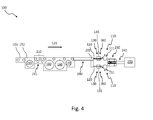
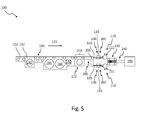
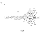
- apparatus 100 for the production of containers 01 from each other at splices 04 by an adhesive 03 connected articles 02, at which splice 04 the article 02 in the finished container 01 immediately and / or only the adhesive 03 spaced from each other comprises at least one device 110, with which at least a part of the whole the splice 04 to be joined by a container 01 to be joined together articles 02 with adhesive 03.
- At least the device 100 further includes one with respect to one in Fig. 2 . Fig. 4 . Fig. 5 and Fig. 6 additionally indicated by an arrow 121 transport 120 of the article 02 to the device 110, with which at least a part of the totality of the splices 04 are provided by a container 01 to be joined together articles 02 with adhesive 03, integrated into the device 110 and / or Drying device 130 arranged directly in front of the device 110, at least for the splices 04 of the adhesives 03 to be joined together to form a container 01, at least for the article 02 to be joined with adhesive 03 in relation to their entirety.
- the drying device 130 can not only dry the parts 04 which comprise the splices 04 but alternatively the entire lateral surfaces 07 of the articles 02 to be joined together by means of adhesive 03 to a container 01 and / or surfaces formed by their lateral surfaces 07 and their bases 05 and / or cover surfaces 06 Article 02. In a further alternative, only areas of the articles 02 in the drying device 130 can be dried, which correspond to certain height ranges of the articles within which the splices are applied at certain distances from one another.
- the containers 01 successively increase as described above in connection with the method, wherein first parts of the finished container 01 are prepared by connecting several articles 02 by means of adhesive 03, which parts are then connected by means of adhesive 03 to the finished container 01 together .
- the drying device 130 can also be provided for splices 04 of parts of a container 01 already formed from a plurality of articles 02 joined together by means of adhesive 03.
- the device 100 can have at least one sensor 131 for detecting moisture and / or moisture arranged in the region of the drying device 130, at least on the splices 04 to be provided at least in part with adhesive 03 with respect to their entirety.
- the sensor 131 has at least the presence and / or the absence of moisture and / or moisture at least in the region of the splice 04 of the 01 to a container 01 by means of adhesive 03 to be interconnected article 02 proportional output signals.
- the sensor 131 may be part of the drying device 130.
- a control device 132 connected to the drying device 130 can be provided, which receives the output signals of the at least one sensor 131 and controls the duration of action and / or the intensity of the action of at least parts of the drying device 130 on the individual articles 02, depending on the output signals. in particular with regard to the lowest possible energy consumption and / or a minimum rate of drying result.
- the drying device 130 can be operated, for example, only if it has been determined that the splices 04 and / or the surfaces of the articles 02 to be joined to a container 01 by an adhesive 03 become moist and / or are wet.
- the alignment of articles 02 according to their arrangement in the finished container 01 is preferably carried out by maintaining and / or changing the orientation of individual and / or several articles 02 with respect to their normal on their serving as footprints surfaces 05 upstanding, in the case of articles 02 in the form straight cylinder parallel to the central axes 08 extending vertical axes, after the articles 02 have been provided at the splice 04 with adhesive 03. Maintaining and / or changing the orientation is preferably carried out by rotation of individual and / or several articles 02 about their axes which in the case of articles 02 are in the form of straight cylinders parallel to their central axes 08.
- the compression preferably takes place at least until a curing agent requiring a curing time 03 has produced an adhesive bond between the articles 02, which withstands a load during further handling of the container 01 or a part of a container 01 produced to date.
- the drying device 130 of the device 100 preferably comprises a heat introduction device 260.
- the heat input device 260 causes a higher heat transfer at least at the splices 04 and / or at the splices 04 precipitated moisture and / or moisture in comparison to a stationary in the environment of the device article 02.
- the higher heat transfer favors an example by Evaporation taking place drying.
- the heat input device 260 thus eliminating moisture and / or moisture at least at the splice 04 on the surfaces of the means of the adhesive 03 to a container 01 to be joined together Article 02, since with increasing heat transfer wet and / or wet splices 04 dry off faster.
- the heat input device 260 may include one or more radiant heaters, preferably infrared radiant heaters, referred to as infrared radiators (IR emitters), for thermal radiation.
- the radiant heater or radiators embodied, for example, as IR radiators can be provided with adhesive 03 at least along a part of a transport path 120 of the article to the device 110, with which at least a part of the totality of the splices 04 of articles 02 to be joined to a container 01 are provided be arranged.
- the at least one heating device 261 may, for example, comprise at least one heating coil and / or at least one furnace and / or at least one heat exchanger, which in another process, such as a device 150 for producing articles 02 comprising, for example, a furnace 151 for so-called preforms and a stretch blower 152, preferably a device 150 for producing articles 02 to be filled with an ingredient, to be filled as a container executed exhaust heat removal of the drying device 130 accessible.
- the at least one heating device and / or at least a part thereof can provide at least along part of a transport path 120 the article 02 to the device 110, with which at least a part of the totality of the splices 04 of articles 02 to be joined to a container 01 are provided with adhesive be arranged.
- the heat can also be supplied by other system components. Without claim to completeness of the enumeration may be at appropriate plant components to a brewhouse and / or a heat exchanger for short-term heating of an ingredient with which the articles 02 are filled, etc. act.
- the means for additional rotational and / or translational movement of transported along the transport path 120 Article 02 get an increase in heat transfer, for example by rotation of the article 02, for example, their normal on their serving as footprints surfaces 05 uprights, at the same time to larger drops or to Thickness and / or moisture deposited by stronger films is shaken off by their inertia, similar to rain drops and / or drops of spray on a centrifugal disc, also referred to as a transparent disc or Kent disc.
- the means 262 for generating an air flow can at least along a part of a transport path 120 of the article 02 to the device 110, with which at least a part of the totality of the splices 04 are provided by a container 01 to be joined together articles 02 with adhesive 03, respectively and / or they may be integrated into such a device 110.
- the air flow may be so strong that it is able to detach one or more drops and / or a moisture film at least from a splice 04 and to tear with it.
- the means 262 for generating an air flow which acts on the moving along the transport path 120 Article 02, for example, a fan and / or for example one or more, one or both sides of at least a portion of the transport path 120 of the article 02 arranged, stationary and / or with articles 02 mitbewegte nozzles 263 for cold and / or hot and / or hot air include, which - if several corresponding nozzles 263 are provided - can be individually controlled.
- the heat input device 260 may comprise at least one cold and / or hot and / or hot air blower as a means for generating an air flow, which acts on the moving along the transport path 120 Article 02.
- the means 262 for generating an air flow at the same time comprise a heating device 261, which heats at least the air surrounding the transport path 120 transported article 02 to a temperature above a temperature in the vicinity of the device 100 , or parts of such a heater 261 or are included by such a heater 261 or parts of such a heater 261.
- the at least one cold and / or hot and / or hot air blower and / or one or more, stationary and / or with the articles 02 mitbewegten nozzles 263 for one or both sides of at least a portion of the transport path 120 of the article 02 arranged. and / or warm and / or hot air may be arranged at least along part of the transport path 120.
- the drying device 130 may, for example as part of the heat introduction device 260, for example as part of means for influencing and changing the orientation of transported along the transport path article 02 corresponding to a maximum Nusselt number, means for rotating the articles 02 on their serving as footprints Base surfaces 05 upstanding vertical axes include.
- reliable drying of, for example, multiple splices 04 distributed over the circumference of one or more articles 02 can be ensured, for example by means of nozzles 263 arranged only on one side of the transport path 120.
- Article 02 can be so even waiving a for a content of the article 02 optionally adverse effect of, for example, hot air and / or thermal radiation proper drying by means of an adhesive 03 to a container 01 together to be connected to Article 02 with elimination of moisture and / or moisture at least at their splice 04.
- the drying device 130 of the device 100 preferably comprises at least part of the transport path 120 of the articles 02 and / or in the region of the device 110, with which at least a part of the totality of the splices 04 of articles 02 to be joined to a container 01 be provided with adhesive 03, extending tunnel 133, as in Fig. 2 . Fig. 3 b) . Fig. 4 . Fig. 5 . Fig. 6 shown.
- the tunnel 133 prevents the uncontrolled escape of heated air and / or flowing air and / or heat radiation and thereby reduces the energy consumption of the drying device 130 and thus the device 100.
- the tunnel 133 prevents the uncontrolled escape of moisture and / or moisture in the removal of moisture and / or moisture at least at the splice 04 by means of an adhesive 03 to a container 01 to be joined together Article 02 must be removed.
- the tunnel 133 may include one or more at least temporarily closable entrance and / or exit hatches and / or locks.
- the entrance and / or exit hatches and / or locks again reduce the uncontrolled escape of heated air and / or flowing air and / or heat radiation and additionally reduce the energy consumption of the drying device 130 and thus the device 100, as well as an additional uncontrolled escape reduce moisture and / or moisture that must be dissipated in the removal of moisture and / or moisture at least at the splice 04 by means of an adhesive 03 to a container 01 to be joined together Article 02.
- the tunnel 133 can as in Fig. 3 b) at least one or more parts of the heat input device 260 are arranged and / or at least partially accommodated.
- At least one or more parts of the drying device 130 may be integrated in or included in the device 110, with which at least a part of the totality of the splices 04 of articles 02 to be joined together to form a container 01 are provided with adhesive 03 Means 110 or parts thereof.
- glue guns or spray nozzles 111 e.g. Fig. 4 . Fig. 5 . Fig. 6
- IR emitters and / or nozzles 263 for cold and / or hot and / or hot air can be controlled separately, for example coaxially or arranged side by side.
- the device 110 includes the device 110, with which at least a portion of the totality of the splices 04 are provided by 02 to be joined to a container 01 articles with adhesive 03, for example, glue guns or spray nozzles 111, with which the splices 04 are provided without contact with adhesive 03, so
- adhesive 03 for example, glue guns or spray nozzles 111
- one or more parts of the drying device 130 for example IR emitters and / or nozzles 263 for cold and / or hot and / or hot air or the like, may be integrated into these, for example, glue guns or spray nozzles 111.
- each glue joint 04 immediately before it is provided with adhesive 03 can be dried exactly at the point where the adhesive 03 should adhere.
- one or more outlets preferably nozzles 263 for cold and / or hot and / or hot air, may be arranged on or in the case of a glue gun or spray nozzle 111.
- At least a part of the drying device 130 for example one or more parts of the heat introduction device 260, such as one or more nozzles 263 for cold and / or hot and / or hot air along at least a portion of the transport path 120 of the article 02 can be movably arranged, and at least along the portion at least temporarily together with the articles 02, for example, on rails, not shown in the drawings, can be moved.
- the heat introduction device 260 such as one or more nozzles 263 for cold and / or hot and / or hot air along at least a portion of the transport path 120 of the article 02 can be movably arranged, and at least along the portion at least temporarily together with the articles 02, for example, on rails, not shown in the drawings, can be moved.
- the device 100 may alternatively or additionally comprise individual or a combination of several features described in connection with the method and / or individual or a combination of several in connection with the prior art and / or in one or more of the Prior art documents mentioned have described features.
- Both a described method and a described device 100 are suitable for eliminating the disadvantages described in the introduction in connection with the prior art.
Landscapes
- Engineering & Computer Science (AREA)
- Architecture (AREA)
- Structural Engineering (AREA)
- Chemical & Material Sciences (AREA)
- Mechanical Engineering (AREA)
- Civil Engineering (AREA)
- Ceramic Engineering (AREA)
- Physics & Mathematics (AREA)
- Materials Engineering (AREA)
- Organic Chemistry (AREA)
- Electromagnetism (AREA)
- Chemical Kinetics & Catalysis (AREA)
- Inorganic Chemistry (AREA)
- Adhesives Or Adhesive Processes (AREA)
- Packages (AREA)
- Auxiliary Devices For And Details Of Packaging Control (AREA)
- Drying Of Solid Materials (AREA)
Applications Claiming Priority (1)
| Application Number | Priority Date | Filing Date | Title |
|---|---|---|---|
| DE102014206672.7A DE102014206672A1 (de) | 2014-04-07 | 2014-04-07 | Vorrichtung und Verfahren zur Herstellung von Gebinden aus untereinander durch ein Haftmittel verklebten Artikeln |
Publications (2)
| Publication Number | Publication Date |
|---|---|
| EP2930117A1 true EP2930117A1 (fr) | 2015-10-14 |
| EP2930117B1 EP2930117B1 (fr) | 2016-06-22 |
Family
ID=52814799
Family Applications (1)
| Application Number | Title | Priority Date | Filing Date |
|---|---|---|---|
| EP15159222.7A Active EP2930117B1 (fr) | 2014-04-07 | 2015-03-16 | Dispositif et procédé de fabrication de gerbes d'articles collées les uns aux autres à l'aide d'un adhésif |
Country Status (3)
| Country | Link |
|---|---|
| EP (1) | EP2930117B1 (fr) |
| CN (1) | CN104973286B (fr) |
| DE (2) | DE202014011299U1 (fr) |
Families Citing this family (3)
| Publication number | Priority date | Publication date | Assignee | Title |
|---|---|---|---|---|
| DE102018115162B4 (de) * | 2018-06-25 | 2020-08-06 | Khs Gmbh | Verfahren zum Etikettieren von Behältern mittels einer Etikettiermaschine |
| DE102018127823A1 (de) | 2018-11-07 | 2020-05-07 | Krones Aktiengesellschaft | Verfahren und System zum Verpacken von Artikeln |
| DE102019118976A1 (de) * | 2019-07-12 | 2021-01-14 | Krones Ag | Verfahren und Vorrichtung zum Herstellen eines Gebindes |
Citations (12)
| Publication number | Priority date | Publication date | Assignee | Title |
|---|---|---|---|---|
| DE2331193A1 (de) | 1973-06-19 | 1975-01-16 | Coors Co Adolph | Grifflose, tragbare einheit aus einer anzahl von behaeltern |
| DE2556424A1 (de) * | 1975-12-15 | 1977-06-23 | Seitz Werke Gmbh | Flaschenverschliessmaschine |
| DE20310721U1 (de) | 2003-04-16 | 2003-09-18 | Pohl, Heinrich Robert, 50769 Köln | Behälter für Lebensmittel, insbesondere für Getränke und Anordnung von Behältern |
| EP2000285A2 (fr) | 2007-06-06 | 2008-12-10 | Krones AG | Dispositif de fabrication et de refroidissement de corps creux en matière synthétique |
| DE102009044271A1 (de) | 2009-10-16 | 2011-04-28 | Krones Ag | Gebinde aus mehreren Behältern und Verfahren zur Herstellung eines solchen Gebindes |
| DE102011106759B3 (de) | 2011-07-05 | 2012-09-13 | Khs Gmbh | Verfahren zur Herstellung von Gebinden |
| DE102011119966B3 (de) | 2011-12-02 | 2012-11-22 | Khs Gmbh | Vorrichtung zur Bildung von Verpackungseinheiten |
| DE102012005925B3 (de) | 2011-12-02 | 2012-11-22 | Khs Gmbh | Vorrichtung zur Bildung von Verpackungseinheiten |
| DE102011119964B3 (de) | 2011-12-02 | 2013-01-17 | Khs Gmbh | Vorrichtung und Verfahren zur Bildung von Verpackungseinheiten |
| DE102011109956B3 (de) | 2011-08-11 | 2013-01-17 | Khs Gmbh | Gebinde |
| DE102011119967B3 (de) | 2011-12-02 | 2013-01-17 | Khs Gmbh | Vorrichtung und Verfahren zur Bildung von Verpackungseinheiten |
| DE102012206297A1 (de) * | 2012-04-17 | 2013-10-17 | Krones Ag | Verfahren und Vorrichtung zur Dosenherstellung und Dosenabfüllung |
Family Cites Families (11)
| Publication number | Priority date | Publication date | Assignee | Title |
|---|---|---|---|---|
| DE3515324A1 (de) | 1985-04-27 | 1986-10-30 | Jagenberg AG, 4000 Düsseldorf | Etikettiermaschine zum aufbringen von rundumetiketten an gefaessen, insbesondere flaschen od.dgl. |
| DE3613317A1 (de) | 1986-04-19 | 1987-10-29 | Jagenberg Ag | Etikettiermaschine zum etikettieren von gegenstaenden mit etiketten, insbesondere rundumetiketten, die von den gegenstaenden einem etikettenstapel unmittelbar entnommen werden |
| DE4105524A1 (de) | 1991-02-22 | 1992-08-27 | Kronseder Maschf Krones | Verfahren und vorrichtung zum anbringen von etiketten an gefaessen |
| DE4141284C2 (de) | 1991-12-14 | 2001-05-31 | Omega Produktions Und Getraenk | Rotativer Behälterträger für eine Behälterbehandlungsmaschine |
| US7074295B2 (en) | 2000-06-06 | 2006-07-11 | Applied Extrusion Technologies, Inc. | Labelling apparatus and method for correcting visual adhesive defects |
| DE102007002675A1 (de) | 2007-01-18 | 2008-07-31 | Khs Ag | Etikettieraggregat |
| DE102007012837A1 (de) * | 2007-03-17 | 2008-09-18 | Krones Ag | Vorrichtung und Verfahren zum Trocknen von Behältern |
| ATE555023T1 (de) | 2007-08-23 | 2012-05-15 | Renner Gmbh | Vorrichtung und verfahren zum etikettieren von gegenständen insbesondere von flüssigkeitsbehältnissen |
| DE102008004774A1 (de) * | 2008-01-16 | 2009-07-23 | Krones Ag | Vorrichtung und Verfahren zur Trocknung von Gegenständen, insbesondere von Flüssigkeitsbehältern |
| DE102010000548A1 (de) * | 2010-02-25 | 2011-08-25 | Krones Ag, 93073 | Transport- und Trocknungsstrecke für einzeln beförderte Artikel und Verfahren zur Trocknung einzeln beförderter Artikel |
| WO2013004340A1 (fr) * | 2011-07-05 | 2013-01-10 | Khs Gmbh | Procédé de réalisation d'emballages multiples à partir de récipients |
-
2014
- 2014-04-07 DE DE202014011299.1U patent/DE202014011299U1/de not_active Expired - Lifetime
- 2014-04-07 DE DE102014206672.7A patent/DE102014206672A1/de active Pending
-
2015
- 2015-03-16 EP EP15159222.7A patent/EP2930117B1/fr active Active
- 2015-04-06 CN CN201510159233.0A patent/CN104973286B/zh active Active
Patent Citations (12)
| Publication number | Priority date | Publication date | Assignee | Title |
|---|---|---|---|---|
| DE2331193A1 (de) | 1973-06-19 | 1975-01-16 | Coors Co Adolph | Grifflose, tragbare einheit aus einer anzahl von behaeltern |
| DE2556424A1 (de) * | 1975-12-15 | 1977-06-23 | Seitz Werke Gmbh | Flaschenverschliessmaschine |
| DE20310721U1 (de) | 2003-04-16 | 2003-09-18 | Pohl, Heinrich Robert, 50769 Köln | Behälter für Lebensmittel, insbesondere für Getränke und Anordnung von Behältern |
| EP2000285A2 (fr) | 2007-06-06 | 2008-12-10 | Krones AG | Dispositif de fabrication et de refroidissement de corps creux en matière synthétique |
| DE102009044271A1 (de) | 2009-10-16 | 2011-04-28 | Krones Ag | Gebinde aus mehreren Behältern und Verfahren zur Herstellung eines solchen Gebindes |
| DE102011106759B3 (de) | 2011-07-05 | 2012-09-13 | Khs Gmbh | Verfahren zur Herstellung von Gebinden |
| DE102011109956B3 (de) | 2011-08-11 | 2013-01-17 | Khs Gmbh | Gebinde |
| DE102011119966B3 (de) | 2011-12-02 | 2012-11-22 | Khs Gmbh | Vorrichtung zur Bildung von Verpackungseinheiten |
| DE102012005925B3 (de) | 2011-12-02 | 2012-11-22 | Khs Gmbh | Vorrichtung zur Bildung von Verpackungseinheiten |
| DE102011119964B3 (de) | 2011-12-02 | 2013-01-17 | Khs Gmbh | Vorrichtung und Verfahren zur Bildung von Verpackungseinheiten |
| DE102011119967B3 (de) | 2011-12-02 | 2013-01-17 | Khs Gmbh | Vorrichtung und Verfahren zur Bildung von Verpackungseinheiten |
| DE102012206297A1 (de) * | 2012-04-17 | 2013-10-17 | Krones Ag | Verfahren und Vorrichtung zur Dosenherstellung und Dosenabfüllung |
Also Published As
| Publication number | Publication date |
|---|---|
| EP2930117B1 (fr) | 2016-06-22 |
| CN104973286A (zh) | 2015-10-14 |
| DE102014206672A1 (de) | 2015-10-08 |
| CN104973286B (zh) | 2017-05-03 |
| DE202014011299U1 (de) | 2019-02-25 |
Similar Documents
| Publication | Publication Date | Title |
|---|---|---|
| DE102014221233A1 (de) | Vorrichtung und Verfahren zum Umgang mit Artikeln | |
| EP2930117B1 (fr) | Dispositif et procédé de fabrication de gerbes d'articles collées les uns aux autres à l'aide d'un adhésif | |
| EP2550210B1 (fr) | Procédé de fabrication d'emballages en feuille plastique | |
| WO2013004340A1 (fr) | Procédé de réalisation d'emballages multiples à partir de récipients | |
| WO2013004339A1 (fr) | Emballage multiple et procédé de réalisation d'un tel emballage multiple | |
| DE102014224519A1 (de) | Etikettiervorrichtung und -verfahren zur Etikettierung von Behältern | |
| EP3402722B1 (fr) | Système de traitement de récipients et procédé de changement du fonctionnement d'un système de traitement de récipients | |
| EP3812288B1 (fr) | Procédé et dispositif de rétractation destinés à la rétractation d'une matière d'emballage thermoplastique sur des articles | |
| DE102019119101A1 (de) | Verfahren und Vorrichtung zum Herstellen von Gebinden mit mehreren unterschiedlichen Getränkebehältern | |
| DE102014104644A1 (de) | Verfahren zur Herstellung eines Gebindes aus untereinander durch ein Haftmittel verbundenen Artikeln | |
| EP4013685A1 (fr) | Dispositif de conditionnement et procédé pour produire une unité d'emballage | |
| DE102013113325A1 (de) | Verfahren und Vorrichtung zur Prüfung von Verklebungen zwischen Artikeln eines Gebindes | |
| DE102019203289A1 (de) | Verfahren und Vorrichtung zur Lagenbildung oder Palettierung von Artikeln, Stückgütern und/oder Gebinden sowie mittels eines solchen Verfahrens gebildete Lagen- oder Palettenanordnung | |
| EP3689761B1 (fr) | Dispositif et procédé de manipulation et / ou d'emballage d'articles | |
| DE102014104645A1 (de) | Gebinde aus mit im Direktdruck aufgebrachten Informationen versehenen, untereinander durch ein Haftmittel verbundenen Artikeln und Verfahren zu dessen Herstellung | |
| DE102009026121A1 (de) | Verfahren zur Handhabung und Behandlung von Flüssigkeitsbehältern und Anordnung mehrerer Vorrichtungen zur Behandlung von Flüssigkeitsbehältern | |
| DE102013113321A1 (de) | Verfahren und Vorrichtung zur Prüfung von Verklebungen zwischen Artikeln eines Gebindes | |
| DE102014104643A1 (de) | Gebinde aus mit Informationsträgern versehenen, untereinander durch ein Haftmittel verbundenen Artikeln und Verfahren zu dessen Herstellung | |
| EP2878544B2 (fr) | Procédé et dispositif de contrôle des collages entre des articles d'une gerbe | |
| EP2848416B1 (fr) | Transport de matériau d'emballage et dispositif de traitement de matériaux d'emballage doté d'un tel système de transport | |
| EP3606832B1 (fr) | Installation et procédé de fabrication d'emballages | |
| DE102021115133A1 (de) | Verfahren zur Ausbildung einer Verpackungseinheit und Vorrichtung zur Herstellung von Verpackungseinheiten | |
| EP2878941B1 (fr) | Procédé et dispositif de contrôle des collages entre des articles d'un conteneur | |
| DE102019128873A1 (de) | Verfahren und Schrumpfvorrichtung zum Aufschrumpfen eines thermoplastischen Verpackungsmaterials auf Artikel | |
| EP2878543B1 (fr) | Procédé et dispositif de fabrication d'une gerbe constituée d'articles reliés ensemble |
Legal Events
| Date | Code | Title | Description |
|---|---|---|---|
| PUAI | Public reference made under article 153(3) epc to a published international application that has entered the european phase |
Free format text: ORIGINAL CODE: 0009012 |
|
| AK | Designated contracting states |
Kind code of ref document: A1 Designated state(s): AL AT BE BG CH CY CZ DE DK EE ES FI FR GB GR HR HU IE IS IT LI LT LU LV MC MK MT NL NO PL PT RO RS SE SI SK SM TR |
|
| AX | Request for extension of the european patent |
Extension state: BA ME |
|
| 17P | Request for examination filed |
Effective date: 20151116 |
|
| RBV | Designated contracting states (corrected) |
Designated state(s): AL AT BE BG CH CY CZ DE DK EE ES FI FR GB GR HR HU IE IS IT LI LT LU LV MC MK MT NL NO PL PT RO RS SE SI SK SM TR |
|
| GRAP | Despatch of communication of intention to grant a patent |
Free format text: ORIGINAL CODE: EPIDOSNIGR1 |
|
| RIC1 | Information provided on ipc code assigned before grant |
Ipc: B65B 35/44 20060101ALI20151209BHEP Ipc: B65G 47/68 20060101ALI20151209BHEP Ipc: B65B 63/08 20060101ALI20151209BHEP Ipc: B65B 35/54 20060101ALI20151209BHEP Ipc: B65B 17/02 20060101AFI20151209BHEP |
|
| INTG | Intention to grant announced |
Effective date: 20160104 |
|
| GRAS | Grant fee paid |
Free format text: ORIGINAL CODE: EPIDOSNIGR3 |
|
| GRAA | (expected) grant |
Free format text: ORIGINAL CODE: 0009210 |
|
| AK | Designated contracting states |
Kind code of ref document: B1 Designated state(s): AL AT BE BG CH CY CZ DE DK EE ES FI FR GB GR HR HU IE IS IT LI LT LU LV MC MK MT NL NO PL PT RO RS SE SI SK SM TR |
|
| REG | Reference to a national code |
Ref country code: GB Ref legal event code: FG4D Free format text: NOT ENGLISH |
|
| REG | Reference to a national code |
Ref country code: CH Ref legal event code: EP |
|
| REG | Reference to a national code |
Ref country code: IE Ref legal event code: FG4D Free format text: LANGUAGE OF EP DOCUMENT: GERMAN |
|
| REG | Reference to a national code |
Ref country code: AT Ref legal event code: REF Ref document number: 807509 Country of ref document: AT Kind code of ref document: T Effective date: 20160715 |
|
| REG | Reference to a national code |
Ref country code: DE Ref legal event code: R096 Ref document number: 502015000062 Country of ref document: DE |
|
| REG | Reference to a national code |
Ref country code: LT Ref legal event code: MG4D |
|
| REG | Reference to a national code |
Ref country code: NL Ref legal event code: MP Effective date: 20160622 |
|
| PG25 | Lapsed in a contracting state [announced via postgrant information from national office to epo] |
Ref country code: FI Free format text: LAPSE BECAUSE OF FAILURE TO SUBMIT A TRANSLATION OF THE DESCRIPTION OR TO PAY THE FEE WITHIN THE PRESCRIBED TIME-LIMIT Effective date: 20160622 Ref country code: LT Free format text: LAPSE BECAUSE OF FAILURE TO SUBMIT A TRANSLATION OF THE DESCRIPTION OR TO PAY THE FEE WITHIN THE PRESCRIBED TIME-LIMIT Effective date: 20160622 Ref country code: NO Free format text: LAPSE BECAUSE OF FAILURE TO SUBMIT A TRANSLATION OF THE DESCRIPTION OR TO PAY THE FEE WITHIN THE PRESCRIBED TIME-LIMIT Effective date: 20160922 |
|
| PG25 | Lapsed in a contracting state [announced via postgrant information from national office to epo] |
Ref country code: NL Free format text: LAPSE BECAUSE OF FAILURE TO SUBMIT A TRANSLATION OF THE DESCRIPTION OR TO PAY THE FEE WITHIN THE PRESCRIBED TIME-LIMIT Effective date: 20160622 Ref country code: SE Free format text: LAPSE BECAUSE OF FAILURE TO SUBMIT A TRANSLATION OF THE DESCRIPTION OR TO PAY THE FEE WITHIN THE PRESCRIBED TIME-LIMIT Effective date: 20160622 Ref country code: RS Free format text: LAPSE BECAUSE OF FAILURE TO SUBMIT A TRANSLATION OF THE DESCRIPTION OR TO PAY THE FEE WITHIN THE PRESCRIBED TIME-LIMIT Effective date: 20160622 Ref country code: HR Free format text: LAPSE BECAUSE OF FAILURE TO SUBMIT A TRANSLATION OF THE DESCRIPTION OR TO PAY THE FEE WITHIN THE PRESCRIBED TIME-LIMIT Effective date: 20160622 Ref country code: LV Free format text: LAPSE BECAUSE OF FAILURE TO SUBMIT A TRANSLATION OF THE DESCRIPTION OR TO PAY THE FEE WITHIN THE PRESCRIBED TIME-LIMIT Effective date: 20160622 Ref country code: GR Free format text: LAPSE BECAUSE OF FAILURE TO SUBMIT A TRANSLATION OF THE DESCRIPTION OR TO PAY THE FEE WITHIN THE PRESCRIBED TIME-LIMIT Effective date: 20160923 |
|
| PG25 | Lapsed in a contracting state [announced via postgrant information from national office to epo] |
Ref country code: EE Free format text: LAPSE BECAUSE OF FAILURE TO SUBMIT A TRANSLATION OF THE DESCRIPTION OR TO PAY THE FEE WITHIN THE PRESCRIBED TIME-LIMIT Effective date: 20160622 Ref country code: RO Free format text: LAPSE BECAUSE OF FAILURE TO SUBMIT A TRANSLATION OF THE DESCRIPTION OR TO PAY THE FEE WITHIN THE PRESCRIBED TIME-LIMIT Effective date: 20160622 Ref country code: IS Free format text: LAPSE BECAUSE OF FAILURE TO SUBMIT A TRANSLATION OF THE DESCRIPTION OR TO PAY THE FEE WITHIN THE PRESCRIBED TIME-LIMIT Effective date: 20161022 Ref country code: SK Free format text: LAPSE BECAUSE OF FAILURE TO SUBMIT A TRANSLATION OF THE DESCRIPTION OR TO PAY THE FEE WITHIN THE PRESCRIBED TIME-LIMIT Effective date: 20160622 Ref country code: CZ Free format text: LAPSE BECAUSE OF FAILURE TO SUBMIT A TRANSLATION OF THE DESCRIPTION OR TO PAY THE FEE WITHIN THE PRESCRIBED TIME-LIMIT Effective date: 20160622 |
|
| REG | Reference to a national code |
Ref country code: FR Ref legal event code: PLFP Year of fee payment: 3 |
|
| PG25 | Lapsed in a contracting state [announced via postgrant information from national office to epo] |
Ref country code: PT Free format text: LAPSE BECAUSE OF FAILURE TO SUBMIT A TRANSLATION OF THE DESCRIPTION OR TO PAY THE FEE WITHIN THE PRESCRIBED TIME-LIMIT Effective date: 20161024 Ref country code: SM Free format text: LAPSE BECAUSE OF FAILURE TO SUBMIT A TRANSLATION OF THE DESCRIPTION OR TO PAY THE FEE WITHIN THE PRESCRIBED TIME-LIMIT Effective date: 20160622 Ref country code: ES Free format text: LAPSE BECAUSE OF FAILURE TO SUBMIT A TRANSLATION OF THE DESCRIPTION OR TO PAY THE FEE WITHIN THE PRESCRIBED TIME-LIMIT Effective date: 20160622 Ref country code: PL Free format text: LAPSE BECAUSE OF FAILURE TO SUBMIT A TRANSLATION OF THE DESCRIPTION OR TO PAY THE FEE WITHIN THE PRESCRIBED TIME-LIMIT Effective date: 20160622 |
|
| REG | Reference to a national code |
Ref country code: DE Ref legal event code: R026 Ref document number: 502015000062 Country of ref document: DE |
|
| PLBI | Opposition filed |
Free format text: ORIGINAL CODE: 0009260 |
|
| 26 | Opposition filed |
Opponent name: KHS GMBH Effective date: 20170321 |
|
| PLAX | Notice of opposition and request to file observation + time limit sent |
Free format text: ORIGINAL CODE: EPIDOSNOBS2 |
|
| PG25 | Lapsed in a contracting state [announced via postgrant information from national office to epo] |
Ref country code: DK Free format text: LAPSE BECAUSE OF FAILURE TO SUBMIT A TRANSLATION OF THE DESCRIPTION OR TO PAY THE FEE WITHIN THE PRESCRIBED TIME-LIMIT Effective date: 20160622 |
|
| PLBB | Reply of patent proprietor to notice(s) of opposition received |
Free format text: ORIGINAL CODE: EPIDOSNOBS3 |
|
| PG25 | Lapsed in a contracting state [announced via postgrant information from national office to epo] |
Ref country code: SI Free format text: LAPSE BECAUSE OF FAILURE TO SUBMIT A TRANSLATION OF THE DESCRIPTION OR TO PAY THE FEE WITHIN THE PRESCRIBED TIME-LIMIT Effective date: 20160622 |
|
| PG25 | Lapsed in a contracting state [announced via postgrant information from national office to epo] |
Ref country code: MC Free format text: LAPSE BECAUSE OF FAILURE TO SUBMIT A TRANSLATION OF THE DESCRIPTION OR TO PAY THE FEE WITHIN THE PRESCRIBED TIME-LIMIT Effective date: 20160622 |
|
| REG | Reference to a national code |
Ref country code: IE Ref legal event code: MM4A |
|
| PG25 | Lapsed in a contracting state [announced via postgrant information from national office to epo] |
Ref country code: LU Free format text: LAPSE BECAUSE OF NON-PAYMENT OF DUE FEES Effective date: 20170316 |
|
| REG | Reference to a national code |
Ref country code: FR Ref legal event code: PLFP Year of fee payment: 4 |
|
| PG25 | Lapsed in a contracting state [announced via postgrant information from national office to epo] |
Ref country code: IE Free format text: LAPSE BECAUSE OF NON-PAYMENT OF DUE FEES Effective date: 20170316 |
|
| REG | Reference to a national code |
Ref country code: BE Ref legal event code: MM Effective date: 20170331 |
|
| PG25 | Lapsed in a contracting state [announced via postgrant information from national office to epo] |
Ref country code: BE Free format text: LAPSE BECAUSE OF NON-PAYMENT OF DUE FEES Effective date: 20170331 |
|
| PG25 | Lapsed in a contracting state [announced via postgrant information from national office to epo] |
Ref country code: MT Free format text: LAPSE BECAUSE OF FAILURE TO SUBMIT A TRANSLATION OF THE DESCRIPTION OR TO PAY THE FEE WITHIN THE PRESCRIBED TIME-LIMIT Effective date: 20160622 |
|
| PG25 | Lapsed in a contracting state [announced via postgrant information from national office to epo] |
Ref country code: AL Free format text: LAPSE BECAUSE OF FAILURE TO SUBMIT A TRANSLATION OF THE DESCRIPTION OR TO PAY THE FEE WITHIN THE PRESCRIBED TIME-LIMIT Effective date: 20160622 |
|
| REG | Reference to a national code |
Ref country code: CH Ref legal event code: PL |
|
| PG25 | Lapsed in a contracting state [announced via postgrant information from national office to epo] |
Ref country code: CH Free format text: LAPSE BECAUSE OF NON-PAYMENT OF DUE FEES Effective date: 20180331 Ref country code: LI Free format text: LAPSE BECAUSE OF NON-PAYMENT OF DUE FEES Effective date: 20180331 |
|
| RDAF | Communication despatched that patent is revoked |
Free format text: ORIGINAL CODE: EPIDOSNREV1 |
|
| STAA | Information on the status of an ep patent application or granted ep patent |
Free format text: STATUS: THE PATENT HAS BEEN GRANTED |
|
| APAH | Appeal reference modified |
Free format text: ORIGINAL CODE: EPIDOSCREFNO |
|
| APBM | Appeal reference recorded |
Free format text: ORIGINAL CODE: EPIDOSNREFNO |
|
| APBP | Date of receipt of notice of appeal recorded |
Free format text: ORIGINAL CODE: EPIDOSNNOA2O |
|
| PG25 | Lapsed in a contracting state [announced via postgrant information from national office to epo] |
Ref country code: HU Free format text: LAPSE BECAUSE OF FAILURE TO SUBMIT A TRANSLATION OF THE DESCRIPTION OR TO PAY THE FEE WITHIN THE PRESCRIBED TIME-LIMIT; INVALID AB INITIO Effective date: 20150316 |
|
| PG25 | Lapsed in a contracting state [announced via postgrant information from national office to epo] |
Ref country code: BG Free format text: LAPSE BECAUSE OF FAILURE TO SUBMIT A TRANSLATION OF THE DESCRIPTION OR TO PAY THE FEE WITHIN THE PRESCRIBED TIME-LIMIT Effective date: 20160622 |
|
| APBQ | Date of receipt of statement of grounds of appeal recorded |
Free format text: ORIGINAL CODE: EPIDOSNNOA3O |
|
| PG25 | Lapsed in a contracting state [announced via postgrant information from national office to epo] |
Ref country code: CY Free format text: LAPSE BECAUSE OF FAILURE TO SUBMIT A TRANSLATION OF THE DESCRIPTION OR TO PAY THE FEE WITHIN THE PRESCRIBED TIME-LIMIT Effective date: 20160622 |
|
| GBPC | Gb: european patent ceased through non-payment of renewal fee |
Effective date: 20190316 |
|
| PG25 | Lapsed in a contracting state [announced via postgrant information from national office to epo] |
Ref country code: MK Free format text: LAPSE BECAUSE OF FAILURE TO SUBMIT A TRANSLATION OF THE DESCRIPTION OR TO PAY THE FEE WITHIN THE PRESCRIBED TIME-LIMIT Effective date: 20160622 |
|
| PG25 | Lapsed in a contracting state [announced via postgrant information from national office to epo] |
Ref country code: GB Free format text: LAPSE BECAUSE OF NON-PAYMENT OF DUE FEES Effective date: 20190316 |
|
| PG25 | Lapsed in a contracting state [announced via postgrant information from national office to epo] |
Ref country code: TR Free format text: LAPSE BECAUSE OF FAILURE TO SUBMIT A TRANSLATION OF THE DESCRIPTION OR TO PAY THE FEE WITHIN THE PRESCRIBED TIME-LIMIT Effective date: 20160622 |
|
| REG | Reference to a national code |
Ref country code: AT Ref legal event code: MM01 Ref document number: 807509 Country of ref document: AT Kind code of ref document: T Effective date: 20200316 |
|
| PG25 | Lapsed in a contracting state [announced via postgrant information from national office to epo] |
Ref country code: AT Free format text: LAPSE BECAUSE OF NON-PAYMENT OF DUE FEES Effective date: 20200316 |
|
| APBU | Appeal procedure closed |
Free format text: ORIGINAL CODE: EPIDOSNNOA9O |
|
| REG | Reference to a national code |
Ref country code: DE Ref legal event code: R100 Ref document number: 502015000062 Country of ref document: DE |
|
| PLCK | Communication despatched that opposition was rejected |
Free format text: ORIGINAL CODE: EPIDOSNREJ1 |
|
| STAA | Information on the status of an ep patent application or granted ep patent |
Free format text: STATUS: OPPOSITION REJECTED |
|
| PLBN | Opposition rejected |
Free format text: ORIGINAL CODE: 0009273 |
|
| 27O | Opposition rejected |
Effective date: 20220208 |
|
| P01 | Opt-out of the competence of the unified patent court (upc) registered |
Effective date: 20230523 |
|
| REG | Reference to a national code |
Ref country code: DE Ref legal event code: R082 Ref document number: 502015000062 Country of ref document: DE Representative=s name: BENNINGER, JOHANNES, DIPL.-ING., DE |
|
| PGFP | Annual fee paid to national office [announced via postgrant information from national office to epo] |
Ref country code: DE Payment date: 20260204 Year of fee payment: 12 |
|
| PGFP | Annual fee paid to national office [announced via postgrant information from national office to epo] |
Ref country code: IT Payment date: 20260220 Year of fee payment: 12 |
|
| PGFP | Annual fee paid to national office [announced via postgrant information from national office to epo] |
Ref country code: FR Payment date: 20260209 Year of fee payment: 12 |