EP2930119A2 - Poignée de transport à disposer sur un emballage - Google Patents
Poignée de transport à disposer sur un emballage Download PDFInfo
- Publication number
- EP2930119A2 EP2930119A2 EP15161385.8A EP15161385A EP2930119A2 EP 2930119 A2 EP2930119 A2 EP 2930119A2 EP 15161385 A EP15161385 A EP 15161385A EP 2930119 A2 EP2930119 A2 EP 2930119A2
- Authority
- EP
- European Patent Office
- Prior art keywords
- connecting element
- transport
- handle
- base part
- handle according
- Prior art date
- Legal status (The legal status is an assumption and is not a legal conclusion. Google has not performed a legal analysis and makes no representation as to the accuracy of the status listed.)
- Withdrawn
Links
- 238000004806 packaging method and process Methods 0.000 claims abstract description 28
- 239000000463 material Substances 0.000 claims abstract description 7
- 238000006073 displacement reaction Methods 0.000 description 6
- 238000004026 adhesive bonding Methods 0.000 description 2
- 206010041953 Staring Diseases 0.000 description 1
- 230000000284 resting effect Effects 0.000 description 1
- 239000007787 solid Substances 0.000 description 1
Images




Classifications
-
- B—PERFORMING OPERATIONS; TRANSPORTING
- B65—CONVEYING; PACKING; STORING; HANDLING THIN OR FILAMENTARY MATERIAL
- B65D—CONTAINERS FOR STORAGE OR TRANSPORT OF ARTICLES OR MATERIALS, e.g. BAGS, BARRELS, BOTTLES, BOXES, CANS, CARTONS, CRATES, DRUMS, JARS, TANKS, HOPPERS, FORWARDING CONTAINERS; ACCESSORIES, CLOSURES, OR FITTINGS THEREFOR; PACKAGING ELEMENTS; PACKAGES
- B65D5/00—Rigid or semi-rigid containers of polygonal cross-section, e.g. boxes, cartons or trays, formed by folding or erecting one or more blanks made of paper
- B65D5/42—Details of containers or of foldable or erectable container blanks
- B65D5/44—Integral, inserted or attached portions forming internal or external fittings
- B65D5/46—Handles
- B65D5/46008—Handles formed separately from the container body
- B65D5/46032—Handles with anchoring elements, e.g. formed by folding a blank
- B65D5/4604—Handles with anchoring elements, e.g. formed by folding a blank not formed by folding a blank
-
- A—HUMAN NECESSITIES
- A45—HAND OR TRAVELLING ARTICLES
- A45F—TRAVELLING OR CAMP EQUIPMENT: SACKS OR PACKS CARRIED ON THE BODY
- A45F5/00—Holders or carriers for hand articles; Holders or carriers for use while travelling or camping
- A45F5/10—Handles for carrying purposes
Definitions
- the invention relates to a transport handle for attachment to a packaging, in particular a cardboard packaging or packaging made of plastic hollow chamber plates or web plates, with an attachable to the packaging base part and a connected via at least one connecting element with the base part handle part.
- transport handles which have a handle part.
- a connecting element is provided at each end of the handle part.
- Each connecting element has a base part at the end.
- Each base part has two laterally attached to the connecting element, aligned obliquely in the manner of an arrow and resiliently formed latching arms. If the base part pressed from the outside through an opening in the package, the locking arms against their respective restoring force in the direction of the connecting element, d. H. towards each other, relocated. After passing through the opening, each locking arm is displaced by its restoring force back to its original orientation to the outside, so that thus in the transport position, the base part rests against the inside of the package and an independent release of the transport handle is not possible.
- the object of the invention is to provide a transport handle, which can be used in packaging both lesser and greater height, without the transport handle protrudes in the rest position of the handle on the underside or top side of the package.
- the handle is gripped and moved to its transport position.
- the handle part In the transport position, the handle part is preferably over the top of the package, so that the handle part can be easily grasped. If the transport handle is no longer needed, the handle is moved to its rest position. Since the handle does not protrude from the top of the package, the package can be stacked well.
- the base part can, for example, at a Side wall of a package adhered, angegetackert or otherwise be positively and / or non-positively attached to the packaging.
- the attachment to the packaging can also be designed such that the base part has no fixed position on the packaging, but is positively fixed in slots which are provided in the packaging, so that a displacement of the base part relative to the packaging is possible.
- the relative displacement of the handle part relative to the base part is additively supplemented by the relative displacement of the base part relative to the packaging.
- a positive connection with a degree of freedom is thus possible, which allows a displacement of the base part relative to the packaging.
- a conceivable embodiment of such a positive connection is characterized, for example, in that the base part has at least one pin, preferably a plurality of pins, wherein each pin engages in a longitudinal slot of the packaging.
- the base part is formed as a web, wherein formed as a web base part in a cavity or a pocket of a z.
- B. double-walled wall of the packaging is arranged, is conceivable.
- the packaging may be, for example, a cardboard packaging.
- plastic packaging such. B. from hollow chamber or web plates existing plastic packaging. Such materials represent a high quality and stable alternative to corrugated board.
- the base part may be formed in one piece. Of course, it is also possible that - provided, for example, two connecting elements are - each connector a separate base part is assigned. Then the base part is formed in several parts.
- At least one connecting element may consist of at least two partial regions, wherein two adjacent partial regions, preferably by means of a hinge, in particular by means of a film hinge, are connected to one another in a pivotable manner.
- the complete transport handle can be integrally formed and thus made of the same material, such as plastic.
- the hinge allows a simple displacement of the handle from the rest position to the transport position.
- Each connecting element can consist of two or even several subregions.
- At least one hinge may be assigned to relieve the hinge in the transport position of the handle portion acting in a longitudinal extent of the subregions relief element.
- the hinge is primarily used to mutually fix the two sections and to pivot. In the transport position, each relief element takes over the actual carrying function, so that the relevant hinge does not have to be particularly solid.
- the relief element may have two spaced-apart lugs, hooks or the like, and in each of the two associated by the respective hinge portions each having a recess may be provided so that in the transport position of the handle portion of a nose or a hook in the a recess and the other nose or the other hook engages in the other recess.
- the relief element may be connected to the connecting element, in particular be formed integrally with the connecting element.
- the connecting element for example, it lends itself to when the complete connecting element and thus also the relief element are made of plastic.
- At least one connecting element may consist of at least two subregions which, seen in the longitudinal direction, are displaceable relative to one another, in particular telescopically telescoping. Such an embodiment also allows a simple displacement of the grip part from the rest position into the transport position and back again.
- the connecting elements may be displaceable relative to one another in the manner of a scissor mechanism.
- each connecting element may have a curved contour and a longitudinal slot extending along the contour, wherein each connecting element is rotatably mounted either on the handle part or on the base part and wherein each longitudinal slot on the base part or on the handle part in the corresponding one Longitudinal slot is associated with protruding projection.
- each connecting element may have a curved contour and a longitudinal slot extending along the contour, and a further longitudinal slot may be provided in the grip part, each connecting element having in the region of its end facing the grip part a projection projecting into the further longitudinal slot and beyond that Longitudinal slot of each connecting element is assigned to the base part at least one projecting into the longitudinal slot projection.
- At least one connecting element may consist of plastic or the like.
- the handle part may be made of plastic or the like.
- the base part may consist of plastic or the like.
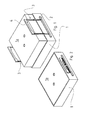
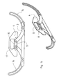
- each package 1 has a lid 1a, wherein the lid 1a have a different height.
- Each transport handle has an attachable in the region of the side wall of a package 1 base 2.
- the base part 2 is in the in the Fig. 1 to 14 illustrated embodiments integrally formed.
- Fig. 15 an embodiment is shown, in which the base part 2 in several parts, namely two parts, is formed.
- the base part 2 is attached to the side of the package 1, for example by gluing.
- a connecting element 3 is provided at each end of the base part 1.
- the transport handle on a handle part 4.
- the two connecting elements 3 engage at the two free ends on the handle part 4.
- Each handle part 4 is displaceable between a rest position and a transport position.
- the distance between the handle part 4 on the one hand and the base part 2 on the other hand in the rest position, as for example in Fig. 2 is shown, and the transport position, such as in Fig. 1 is shown, smaller.
- the Fig. 1 and 2 can be seen, is each connecting element 3 in the rest position of the handle part 4 is not below the base part 2 before.
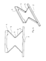
- each connecting element 3 has a zigzag-shaped course.
- Each connecting element 3 consists in this embodiment of an elastically or plastically deformable material. Thus, each connecting element 3 is deformed in the transport position in a graderen course.
- the other embodiments of the transport handles according to the invention have connecting elements 3 with at least one rigid portion 5.
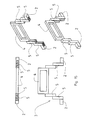
- each connecting element 3 consists of at least two subregions 5. Two adjacent subregions 5 are fixed to one another via a film hinge 6 and pivotable relative to each other.
- each film hinge 6 assigned a acting in the longitudinal extent of the subregions 5 in the transport position relief element 7.
- the relief element 7 has two spaced apart hooks 8.
- a recess 9 is provided in each case.
- the one hook 8 engages in the one recess 9 and the other hook 8 in the other recess 9 a.
- the relief element 7 is - as in Fig. 7 shown - formed integrally with the connecting element 3.
- each connecting element 3 consists of a total of four subregions 5.
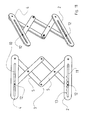
- FIG. 10 and 11 an embodiment is shown in which the connecting elements 3 are displaceable against each other in the manner of a Scherenmechanismusses.
- an elongated recess 10, 11 is provided in the handle part 4 and in the base part 2 in each case.
- Each connecting element 3 consists of two subregions 5, which are hinged together.
- the two free ends of one of the two connecting elements 3 are in turn stationary, but rotatably attached to the base part 2 and the handle part 4.
- a respective projection 12 is provided, which engages in the elongated recess 10 in the handle part 4 and in the elongated recess 11 in the base part 2.
- the upper edge of the elongate recess 11 is provided in the base part 2 with locking recesses 13 into which the relevant projection 12 can engage.
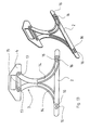
- each of the two connecting elements 3 has a curved contour and a longitudinal slot 14 extending along the contour.
- a further longitudinal slot 15 is provided in the grip part 4.
- each connecting element 3 in the end which cooperates with the handle part 4, a projection 17 which engages in the further longitudinal slot 15 in the handle part 4.
- each connecting element 3 consists of a total of two subregions 5, which are seen in the illustrated embodiment in the longitudinal direction against each other displaced.
- the partial areas 5 of a connecting element 3 are all arranged side by side in the rest position.
- the subregions 5 of a connecting element 3 are formed telescopically one inside the other.
Landscapes
- Engineering & Computer Science (AREA)
- Mechanical Engineering (AREA)
- Details Of Rigid Or Semi-Rigid Containers (AREA)
Applications Claiming Priority (1)
| Application Number | Priority Date | Filing Date | Title |
|---|---|---|---|
| DE202014101684.8U DE202014101684U1 (de) | 2014-04-09 | 2014-04-09 | Transportgriff zur Anbringung an einer Verpackung |
Publications (2)
| Publication Number | Publication Date |
|---|---|
| EP2930119A2 true EP2930119A2 (fr) | 2015-10-14 |
| EP2930119A3 EP2930119A3 (fr) | 2016-01-06 |
Family
ID=52807635
Family Applications (1)
| Application Number | Title | Priority Date | Filing Date |
|---|---|---|---|
| EP15161385.8A Withdrawn EP2930119A3 (fr) | 2014-04-09 | 2015-03-27 | Poignée de transport à disposer sur un emballage |
Country Status (2)
| Country | Link |
|---|---|
| EP (1) | EP2930119A3 (fr) |
| DE (1) | DE202014101684U1 (fr) |
Cited By (1)
| Publication number | Priority date | Publication date | Assignee | Title |
|---|---|---|---|---|
| CN107600628A (zh) * | 2017-10-12 | 2018-01-19 | 天津市安第斯科技有限公司 | 多功能工业水性漆桶及其制造工艺 |
Families Citing this family (1)
| Publication number | Priority date | Publication date | Assignee | Title |
|---|---|---|---|---|
| CN111994414A (zh) * | 2020-07-25 | 2020-11-27 | 潍坊和合包装有限公司 | 一种高性能防潮包装箱 |
Family Cites Families (6)
| Publication number | Priority date | Publication date | Assignee | Title |
|---|---|---|---|---|
| US3113651A (en) * | 1962-11-20 | 1963-12-10 | Philadelphia Handle Company | Collapsible flush-lying handle |
| US3168173A (en) * | 1963-08-07 | 1965-02-02 | Koffler Sol | Collapsible handle |
| US3382526A (en) * | 1966-02-28 | 1968-05-14 | Mattel Inc | Handle construction |
| US3447196A (en) * | 1968-03-21 | 1969-06-03 | Philadelphia Handle Co | Collapsible handle operable by exertion of a push downwardly on one end thereof |
| US20090174203A1 (en) * | 2008-01-09 | 2009-07-09 | Sung Bong Kim | Collapsible Carrying Strap |
| US7934289B2 (en) * | 2008-04-01 | 2011-05-03 | Carimax Corporation | Foldable cross-patterned pull-handle and bag having the same |
-
2014
- 2014-04-09 DE DE202014101684.8U patent/DE202014101684U1/de not_active Expired - Lifetime
-
2015
- 2015-03-27 EP EP15161385.8A patent/EP2930119A3/fr not_active Withdrawn
Non-Patent Citations (1)
| Title |
|---|
| None |
Cited By (1)
| Publication number | Priority date | Publication date | Assignee | Title |
|---|---|---|---|---|
| CN107600628A (zh) * | 2017-10-12 | 2018-01-19 | 天津市安第斯科技有限公司 | 多功能工业水性漆桶及其制造工艺 |
Also Published As
| Publication number | Publication date |
|---|---|
| EP2930119A3 (fr) | 2016-01-06 |
| DE202014101684U1 (de) | 2015-07-20 |
Similar Documents
| Publication | Publication Date | Title |
|---|---|---|
| DE60309875T2 (de) | Abnehmbares griffelement zum anbringen an behälter von verschiedenen dicken | |
| DE2419818A1 (de) | Pinzette | |
| DE29920133U1 (de) | Klappmesser | |
| EP3587294A1 (fr) | Récipient empilable pourvu de mécanisme de raccordement | |
| EP2128035A1 (fr) | Verrou pour récipients de transport dotés de parois latérales repliables | |
| EP2930119A2 (fr) | Poignée de transport à disposer sur un emballage | |
| EP3636104B1 (fr) | Dispositif d'accouplement pour le guidage de coulisse | |
| EP3632808A1 (fr) | Pallette en plastic | |
| EP2899132B1 (fr) | Récipient doté d'une ouverture de chargement refermable | |
| DE102014102626A1 (de) | Kettenglied für eine Energieführungskette | |
| DE102007049944A1 (de) | Flachbildschirm-Haltevorrichtung | |
| EP3078454A1 (fr) | Dispositif comprenant une surface de prehension parallele | |
| DE202010000679U1 (de) | Brecheisen mit schneller Winkelverstellung | |
| DE202020101897U1 (de) | Infektionsschutzverkleidung für Handgriffe | |
| EP2539159B1 (fr) | Mécanisme de classeur | |
| DE102013101552A1 (de) | Spreizer für die Herz- und Thoraxchirurgie | |
| EP2591735B1 (fr) | Prolongation pour un levier osseux ou un écarteur de plaies | |
| EP2455293A1 (fr) | Boîte pliante carrée pouvant être suspendue | |
| DE19824221C1 (de) | Hakeneinrichtung für Fahrzeuge, insbesondere Lastkraftwagen | |
| EP1274911B1 (fr) | Fermeture | |
| EP3043142A1 (fr) | Metre pliant | |
| DE202016006430U1 (de) | Handgriff | |
| DE202015005453U1 (de) | Gepäckstück | |
| DE1536520C (de) | Musterbuch | |
| DE202011000116U1 (de) | Griffanordnung einer Gartenschere |
Legal Events
| Date | Code | Title | Description |
|---|---|---|---|
| PUAI | Public reference made under article 153(3) epc to a published international application that has entered the european phase |
Free format text: ORIGINAL CODE: 0009012 |
|
| AK | Designated contracting states |
Kind code of ref document: A2 Designated state(s): AL AT BE BG CH CY CZ DE DK EE ES FI FR GB GR HR HU IE IS IT LI LT LU LV MC MK MT NL NO PL PT RO RS SE SI SK SM TR |
|
| AX | Request for extension of the european patent |
Extension state: BA ME |
|
| PUAL | Search report despatched |
Free format text: ORIGINAL CODE: 0009013 |
|
| AK | Designated contracting states |
Kind code of ref document: A3 Designated state(s): AL AT BE BG CH CY CZ DE DK EE ES FI FR GB GR HR HU IE IS IT LI LT LU LV MC MK MT NL NO PL PT RO RS SE SI SK SM TR |
|
| AX | Request for extension of the european patent |
Extension state: BA ME |
|
| RIC1 | Information provided on ipc code assigned before grant |
Ipc: A45C 13/26 20060101ALI20151127BHEP Ipc: B65D 5/46 20060101AFI20151127BHEP Ipc: A45F 5/10 20060101ALI20151127BHEP |
|
| STAA | Information on the status of an ep patent application or granted ep patent |
Free format text: STATUS: THE APPLICATION HAS BEEN WITHDRAWN |
|
| 18W | Application withdrawn |
Effective date: 20160706 |