EP2930125A1 - Flaschenförmiger behälter mit innenbeutel - Google Patents
Flaschenförmiger behälter mit innenbeutel Download PDFInfo
- Publication number
- EP2930125A1 EP2930125A1 EP15001013.0A EP15001013A EP2930125A1 EP 2930125 A1 EP2930125 A1 EP 2930125A1 EP 15001013 A EP15001013 A EP 15001013A EP 2930125 A1 EP2930125 A1 EP 2930125A1
- Authority
- EP
- European Patent Office
- Prior art keywords
- bottle
- inner bag
- shaped container
- container
- container according
- Prior art date
- Legal status (The legal status is an assumption and is not a legal conclusion. Google has not performed a legal analysis and makes no representation as to the accuracy of the status listed.)
- Granted
Links
Images
Classifications
-
- B—PERFORMING OPERATIONS; TRANSPORTING
- B65—CONVEYING; PACKING; STORING; HANDLING THIN OR FILAMENTARY MATERIAL
- B65D—CONTAINERS FOR STORAGE OR TRANSPORT OF ARTICLES OR MATERIALS, e.g. BAGS, BARRELS, BOTTLES, BOXES, CANS, CARTONS, CRATES, DRUMS, JARS, TANKS, HOPPERS, FORWARDING CONTAINERS; ACCESSORIES, CLOSURES, OR FITTINGS THEREFOR; PACKAGING ELEMENTS; PACKAGES
- B65D83/00—Containers or packages with special means for dispensing contents
- B65D83/14—Containers for dispensing liquid or semi-liquid contents by internal gaseous pressure, i.e. aerosol containers comprising propellant
- B65D83/60—Containers for dispensing liquid or semi-liquid contents by internal gaseous pressure, i.e. aerosol containers comprising propellant with contents and propellant separated
- B65D83/62—Containers for dispensing liquid or semi-liquid contents by internal gaseous pressure, i.e. aerosol containers comprising propellant with contents and propellant separated by membranes, bags or the like
-
- B—PERFORMING OPERATIONS; TRANSPORTING
- B65—CONVEYING; PACKING; STORING; HANDLING THIN OR FILAMENTARY MATERIAL
- B65D—CONTAINERS FOR STORAGE OR TRANSPORT OF ARTICLES OR MATERIALS, e.g. BAGS, BARRELS, BOTTLES, BOXES, CANS, CARTONS, CRATES, DRUMS, JARS, TANKS, HOPPERS, FORWARDING CONTAINERS; ACCESSORIES, CLOSURES, OR FITTINGS THEREFOR; PACKAGING ELEMENTS; PACKAGES
- B65D83/00—Containers or packages with special means for dispensing contents
- B65D83/14—Containers for dispensing liquid or semi-liquid contents by internal gaseous pressure, i.e. aerosol containers comprising propellant
- B65D83/38—Details of the container body
Definitions
- the invention relates to a bottle-shaped container made of a hard plastic and a soft inner bag for receiving a liquid or creamy filling material, in particular a medical device, and with a valve for dispensing the filling material.
- Such a container is out DE 10 2010 009 102.2 A1 and DE 10 2010 009 101.4 known as a double-walled squeeze bottle, which is made by coextrusion blown from two layers that do not connect with each other.
- the outer layer is made of a hard but elastic plastic and is compressed by hand to release filling material from a valve.
- These squeeze bottles are designed so that after the discharge of filling material no air enters the inner bag, so that they are suitable for receiving medical devices.
- the pressure equalization after discharge of filler material is done by air entering through a hole in the outer container in the space between the outer container and the inner bag, wherein the air supply is effected by a one-way valve, which is closed during the crimping to the outside.
- the present invention has for its object to provide a bottle-shaped container of the type considered, in which the above disadvantages are avoided or at least largely eliminated.
- the present invention provides that in the inwardly and outwardly closed space between the inner bag and the container, a gas is present with such an overpressure that exits the filling material when the valve is open.
- the gas may be air, preferably sterile air, or an inert gas, such as nitrogen, which can not chemically attack or interfere with the inner bag and its contents.
- the gas pressure in the gap should be so large that virtually the entire bag contents can be delivered.
- the gas pressure at maximum filled inner bag is 6 to 12 bar, preferably between 8 and 10 bar. It is provided that the volume of the filled inner bag is in such a ratio to the volume of the container, that the pressure at emptied inner bag is still about 1 to 3 bar. As a result, the inner bag can be almost completely emptied when the valve is open.
- valve with a short piece of pipe protrudes into the inner bag, wherein the otherwise closed edge of the inner bag is attached tightly to the circumference of the tube.
- annular plug is tightly mounted on this tube, which engages in the container neck and this tightly closes, and that above a collar is attached to the tube which surrounds the container neck on the outside.
- a ring seal is inserted, which rests on the upper edge of the container neck and is pressed against this.
- the collar may consist of a sheet material and be pressed with a peripheral wall to the outside of the container neck.
- the container can be manufactured by extrusion blow molding and therefore have a weld at the bottom.
- This weld can be designed as outwardly projecting web.
- An important requirement of the bottle-shaped container according to the invention is that the container should be stable and not bulged so that it can easily tilt by the introduction of the compressed gas into the space between the inner bag and the container.
- the bottom is retracted relative to its edge, such that the web projecting from the bottom does not protrude beyond the edge of the bottom.
- the web increases the resistance of the soil against excessive bulging, so that the container is stable even at maximum gas pressure.
- the container can be manufactured by injection blow molding, wherein first a cylindrical preform is injected, whose diameter corresponds to that of the finished container neck.
- the bottom is retracted inwardly from its edge, so that it can not bulge beyond the edge of the soil at the later internal pressure load.
- the expansion in the bottom region of the container as a result of the application of the overpressure depends substantially on the inner radius of the bottom edge. It proves to be particularly advantageous if the inner radius of the bottom edge before introduction of the compressed gas into the intermediate space is 5 to 8 mm, with an inner radius of 6 mm in experiments leading to the lowest elongation in the radius and the lowest buckling of the bottom.
- the wall thickness of the container is preferably about 3 to 4 mm.
- the container In order for the container to have the required strength to withstand the pressure load in the long term, its plastic should have a high modulus of elasticity and a high yield stress.
- the invention proposes that the plastic used has an E-modulus of about 3,300 (MPa) and a yield stress of about 65 (MPa).
- a material that is suitable for the blowing process and has these properties is RADITER E 87 G from Radici Plastics.
- a container made of this or a similar material has the required strength and temperature resistance even in long-term behavior and is gas-tight, which is the prerequisite for maintaining the overpressure for a sufficiently long time.
- an aluminum foil is preferred, but also an easily deformable plastic comes into consideration, which may be provided with a diffusion barrier layer.
- this can be filled with a suitable device first with gas at an overpressure of 1 to 3 bar, whereupon the inner bag connected to the valve is inserted in the folded or rolled state in the container. This can also be done in reverse order. Subsequently, the container is sealed by means of the seals and the collar described above. In this state prevails in the space of the above-mentioned internal pressure of 1 to 3 bar. Subsequently, the container contents are pressed into the inner bag, wherein the overpressure in the intermediate space increases as a result of the expansion of the inner bag to preferably 8 to 10 bar. After filling, the valve is closed, making the container ready for use.
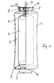
- FIG. 1 shows a bottle-shaped container 1 made of a rigid plastic material, the bottom 2 is concave retracted inward, so that the container 1 rests on the annular edge 3.
- the edge 3 has an inner diameter R, which is in the unloaded state of the container 1 5 to 8 mm, preferably 6 mm.
- the bottle-shaped container is manufactured by extrusion blow molding, it has at the bottom 2 a central weld, which may be formed as an outwardly projecting web 4, which is offset from the edge 3 of the bottom 2 so far back that he after application of an overpressure 8 to 10 bar in the space 5 between the inner wall of the container 1 and the outside of an inner bag 6 does not protrude beyond the edge 2 addition, whereby otherwise the stability of the container would be impaired.
- the web 4 can increase the stability of the soil against buckling due to the overpressure.
- the bottom 2 may also be formed without a projecting web.
- the inner bag 6 is inserted, which is fixed to the outer periphery of a valve 7. Above this is an annular sealing body 8, which engages tightly in the neck 9 of the container 1, as well as above a consisting of a sheet material collar 10 which engages around the container neck 9 outside. On the upper edge of the container neck an annular seal 11 is arranged, which is pressed firmly by the collar 10. In this way, the gap 5 is sealed against both the outer environment and against the inner bag 6.
- the inner bag 6 is first inserted in the rolled-up or folded state into the container 1, in which a gas is introduced at an overpressure of 1 to 3 bar with a suitable device. After sealing the container neck, a liquid or creamy product, preferably a medical device, is pressed into the container 6 through the valve 7, which expands so that the overpressure in the intermediate space 5 rises to 8 to 10 bar. Then the valve 7 closes and the container is ready to use. As a result of the Overpressure in the container 1, virtually the entire contents of the inner bag 6 can be delivered by opening the valve 7.
Landscapes
- Chemical & Material Sciences (AREA)
- Dispersion Chemistry (AREA)
- Engineering & Computer Science (AREA)
- Mechanical Engineering (AREA)
- Containers And Packaging Bodies Having A Special Means To Remove Contents (AREA)
- Containers Having Bodies Formed In One Piece (AREA)
- Packages (AREA)
Abstract
Description
- Die Erfindung betrifft einen flaschenförmigen Behälter aus einem harten Kunststoff und einem weichen Innenbeutel zur Aufnahme eines flüssigen oder cremigen Füllmaterials, insbesondere eines Medizinprodukts, und mit einem Ventil zur Abgabe des Füllmaterials.
- Ein derartiger Behälter ist aus
DE 10 2010 009 102.2 A1 undDE 10 2010 009 101.4 als doppelwandige Quetschflasche bekannt, die im Coextrusions-Blasverfahren aus zwei Schichten hergestellt ist, die keine Verbindung miteinander eingehen. Die Außenschicht besteht aus einem harten, aber elastischen Kunststoff und wird von Hand zusammengedrückt, um Füllmaterial aus einem Ventil abzugeben. Diese Quetschflaschen sind so ausgebildet, dass nach der Abgabe von Füllmaterial keine Luft in den Innenbeutel eintritt, so dass sie zur Aufnahme von Medizinprodukten geeignet sind. Der Druckausgleich nach Abgabe von Füllmaterial geschieht dadurch, dass in den Zwischenraum zwischen dem Außenbehälter und dem Innenbeutel Luft durch ein Loch in dem Außenbehälter eintritt, wobei die Luftzufuhr durch ein Einwegventil erfolgt, das beim Quetschvorgang nach außen hin verschlossen ist. Bei solchen Quetschflaschen besteht das Problem, dass eine nicht unbeträchtliche Restmenge in dem Innenbeutel zurück bleiben kann, die nur mit einem beträchtlichen Aufwand ausbringbar ist. Das Ventil, das den Zutritt von Luft in den Innenbeutel verhindert, hat einen verhältnismäßig aufwändigen Aufbau, und wenn das Rückschlagventil undicht werden sollte, kann die Abgabe von Füllmaterial unmöglich werden. - Der vorliegenden Erfindung liegt die Aufgabe zugrunde, einen flaschenförmigen Behälter der betrachteten Art anzugeben, bei dem die obigen Nachteile vermieden oder wenigstens weitestgehend abgestellt sind.
- Diese Aufgabe wird erfindungsgemäß durch die Merkmale des Patentanspruchs 1 gelöst.
- Vorteilhafte Ausgestaltungen der Erfindung sind in den Unteransprüchen gekennzeichnet.
- Die vorliegende Erfindung sieht vor, dass in dem nach innen und außen geschlossenen Zwischenraum zwischen dem Innenbeutel und dem Behälter ein Gas mit einem solchen Überdruck vorhanden ist, dass bei geöffnetem Ventil das Füllmaterial austritt. Bei dem Gas kann es sich um Luft, vorzugsweise sterile Luft handeln, oder aber um ein inertes Gas wie Stickstoff, das den Innenbeutel und dessen Inhalt praktisch nicht chemisch angreifen bzw. beeinträchtigen kann.
- Der Gasdruck in dem Zwischenraum soll so groß sein, dass praktisch der gesamte Beutelinhalt abgegeben werden kann. Hierzu wird vorgeschlagen, dass der Gasdruck bei maximal gefüllten Innenbeutel 6 bis 12 bar, vorzugsweise zwischen 8 und 10 bar beträgt. Dabei ist vorgesehen, dass das Volumen des gefüllten Innenbeutels in einem solchen Verhältnis zum Volumen des Behälters steht, dass der Druck bei entleertem Innenbeutel noch etwa 1 bis 3 bar beträgt. Dies hat zur Folge, dass der Innenbeutel bei geöffnetem Ventil praktisch vollständig geleert werden kann.
- In weiteren Einzelheiten wird vorgeschlagen, dass das Ventil mit einem kurzen Rohrstück in den Innenbeutel ragt, wobei der ansonsten geschlossene Rand des Innenbeutels dicht am Umfang des Röhrchens befestigt ist. Darüber ist an diesem Röhrchen ein ringförmiger Stopfen dicht angebracht, der in den Behälterhals eingreift und diesen dicht verschließt, und dass darüber ein Kragen an dem Röhrchen befestigt ist, der den Behälterhals außen umschließt. In den Kragen ist eine Ringdichtung eingelegt, die auf dem oberen Rand des Behälterhalses aufliegt und an diesen angepresst ist. Hierdurch ist der Zwischenraum zwischen dem Innenbeutel und dem Behälter gegenüber der Umgebung und dem Innenraum des Innenbeutels abgedichtet. Der Kragen kann aus einem Blechmaterial bestehen und mit einer Umfangswand an die Außenseite des Behälterhalses angepresst sein.
- Nach einem weiteren Vorschlag der Erfindung kann der Behälter im Extrusionsblasverfahren hergestellt sein und daher am Boden eine Schweißnaht haben. Diese Schweißnaht kann als nach außen vorstehender Steg ausgebildet sein. Eine wichtige Anforderung an den erfindungsgemäßen flaschenförmigen Behälter besteht darin, dass der Behälter standfest sein soll und durch das Einbringen des Druckgases in den Zwischenraum zwischen dem Innenbeutel und dem Behälter nicht so ausbeult, dass er leicht kippen kann.
- Um diese Standfestigkeit des Behälters zu erreichen, ist vorgesehen, dass der Boden gegenüber seinem Rand eingezogen ist, derart, dass der von dem Boden nach außen vorstehende Steg nicht über den Rand des Bodens hinaus vorsteht. Der Steg erhöht den Widerstand des Bodens gegen ein zu großes Ausbeulen, so dass der Behälter auch bei maximalem Gasdruck standfest ist.
- Nach einem alternativen Vorschlag der Erfindung kann der Behälter im Spritzblasverfahren hergestellt werden, wobei zunächst ein zylindrischer Vorformling gespritzt wird, dessen Durchmesser demjenigen des fertigen Behälterhalses entspricht. Bei dem nachfolgenden Blasvorgang ist wiederum bevorzugt, dass der Boden gegenüber seinem Rand nach innen eingezogen ist, so dass er bei der späteren Innendruckbelastung nicht über den Rand des Bodens hinaus ausbeulen kann.
- Es hat sich herausgestellt, dass die Dehnung im Bodenbereich des Behälters infolge der Aufbringung des Überdrucks wesentlich von dem Innenradius des Bodenrandes abhängt. Als besonders vorteilhaft erweist es sich, wenn der Innenradius des Bodenrandes vor Einbringung des Druckgases in den Zwischenraum 5 bis 8 mm beträgt, wobei ein Innenradius von 6 mm bei Versuchen zu der geringsten Dehnung im Radius und dem geringsten Ausbeulen des Bodens führten. Hierbei beträgt die Wandstärke des Behälters vorzugsweise etwa 3 bis 4 mm.
- Damit der Behälter die erforderliche Festigkeit hat, um auch langfristig der Druckbelastung stand zu halten, sollte sein Kunststoff ein hohes E-Modul und eine hohe Streckspannung haben. Hierzu schlägt die Erfindung vor, dass der verwendete Kunststoff ein E-Modul von etwa 3.300 (MPa) und eine Streckspannung von etwa 65 (MPa) aufweist. Ein Material, das für das Blasverfahren geeignet ist und diese Eigenschaften hat, ist RADITER E 87 G von Radici Plastics.
- Ein Behälter aus diesem oder einem ähnlichen Material hat auch im Langzeitverhalten die erforderliche Festigkeit und Temperaturbeständigkeit und ist gasdicht, was die Voraussetzung dafür ist, dass der Überdruck ausreichend lange aufrecht erhalten bleibt.
- Als Material für den Innenbeutel wird eine Aluminiumfolie bevorzugt, wobei aber auch ein leicht verformbarer Kunststoff in Betracht kommt, der mit einer Diffusionssperrschicht versehen sein kann.
- Zur Fertigstellung des Behälters kann dieser mit einer geeigneten Vorrichtung zunächst mit Gas mit einem Überdruck von 1 bis 3 bar gefüllt werden, woraufhin der mit dem Ventil verbundene Innenbeutel im zusammengefalteten oder zusammengerollten Zustand in den Behälter eingesetzt wird. Dies kann auch in umgekehrter Reihenfolge erfolgen. Anschließend wird der Behälter mittels der oben beschriebenen Dichtungen und des Kragens dicht verschlossen. In diesem Zustand herrscht in dem Zwischenraum der oben erwähnte Innendruck von 1 bis 3 bar. Anschließend wird der Behälterinhalt in den Innenbeutel gepresst, wobei der Überdruck in dem Zwischenraum infolge der Ausdehnung des Innenbeutels auf vorzugsweise 8 bis 10 bar ansteigt. Nach dem Füllvorgang wird das Ventil geschlossen, womit der Behälter fertig zum Gebrauch ist.
- Weitere Einzelheiten der Erfindung ergeben sich aus der nachfolgenden Beschreibung einer bevorzugten Ausführungsform des Behälters sowie anhand der Zeichnungen. Dabei zeigen:
- Figur 1
- einen zusammengesetzten Behälter, zur Hälfte in einer Ansicht und in einem Vertikalschnitt und
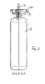
- Figur 2
- eine Darstellung ähnlich wie
Figur 1 , jedoch ohne den flaschenförmigen Behälter. -
Figur 1 zeigt einen flaschenförmigen Behälter 1 aus einem starren Kunststoffmaterial, dessen Boden 2 konkav nach innen eingezogen ist, so dass der Behälter 1 auf dem ringförmigen Rand 3 aufruht. Der Rand 3 hat einen Innendurchmesser R, der im unbelasteten Zustand des Behälters 1 5 bis 8 mm, vorzugsweise 6 mm beträgt. Wenn der flaschenförmige Behälter im Extrusionsblasverfahren hergestellt ist, hat er am Boden 2 eine mittige Schweißnaht, die als ein nach außen vorstehender Steg 4 weitergebildet sein kann, der gegenüber dem Rand 3 des Bodens 2 soweit zurück versetzt ist, dass er nach Aufbringen eines Überdrucks von 8 bis 10 bar in den Zwischenraum 5 zwischen der Innenwand des Behälter 1 und der Außenseite eines Innenbeutels 6 nicht über den Rand 2 hinaus vorsteht, wodurch anderenfalls die Standfestigkeit des Behälters beeinträchtigt wäre. Der Steg 4 kann die Stabilität des Bodens gegen ein Ausbeulen infolge des Überdrucks erhöhen. Der Boden 2 kann aber auch ohne vorstehenden Steg ausgebildet sein. - In den Behälter 1 ist der Innenbeutel 6 eingesetzt, der am Außenumfang eines Ventils 7 befestigt ist. Darüber befindet sich ein ringförmiger Dichtungskörper 8, der dicht in den Hals 9 des Behälters 1 eingreift, sowie darüber ein aus einem Blechmaterial bestehender Kragen 10, der den Behälterhals 9 außen umgreift. Auf dem oberen Rand des Behälterhalses ist eine Ringdichtung 11 angeordnet, die von dem Kragen 10 fest angepresst wird. Auf diese Weise ist der Zwischenraum 5 sowohl gegenüber der äußeren Umgebung als auch gegenüber dem Innenbeutel 6 abgedichtet.
- Der Innenbeutel 6 wird zunächst im zusammengerollten oder zusammengefalteten Zustand in den Behälter 1 eingesetzt, in den ein Gas mit einem Überdruck von 1 bis 3 bar mit einer geeigneten Vorrichtung eingebracht wird. Nach Abdichtung des Behälterhalses wird durch das Ventil 7 ein flüssiges oder cremiges Produkt, vorzugsweise ein Medizinprodukt, in den Behälter 6 eingepresst, der sich dabei so ausdehnt, dass der Überdruck in dem Zwischenraum 5 auf 8 bis 10 bar ansteigt. Daraufhin schließt das Ventil 7 und der Behälter ist gebrauchsfertig. Infolge des Überdrucks in dem Behälter 1 kann praktisch der gesamte Inhalt des Innenbeutels 6 durch Öffnen des Ventils 7 abgegeben werden.
Claims (10)
- Flaschenförmiger Behälter (1) aus einem harten Kunststoff, mit einem weichen Innenbeutel (6) zur Aufnahme eines flüssigen oder cremigen Füllmaterials, insbesondere eines Medizinproduktes, und mit einem Ventil (7) zur Abgabe des Füllmaterials,
dadurch gekennzeichnet,
dass in den abgedichteten Zwischenraum (5) zwischen dem Innenbeutel (6) und dem Behälter (1) ein Gas mit einem solchen Überdruck eingebracht ist, dass bei geöffnetem Ventil (7) das Füllmaterial austritt. - Flaschenförmiger Behälter nach Anspruch 1,
dadurch gekennzeichnet,
dass der Gasdruck bei maximal gefülltem Innenbeutel (6) 6 bis 12 bar, vorzugsweise 8 bis 10 bar beträgt. - Flaschenförmiger Behälter nach Anspruch 1 oder 2,
dadurch gekennzeichnet,
dass der Innenbeutel (6) dicht am Umfang des Ventils (7) befestigt ist und dass an dem Ventil (7) ein ringförmiger Stopfen (8), der dicht in den Behälterhals (9) eingreift, und ein mit einer Dichtung (11) versehener Kragen (10) angebracht sind, der den Behälterhals (9) außen umschließt, so dass der Zwischenraum (5) zwischen dem Innenbeutel (6) und dem Behälter (1) gegenüber der Umgebung abgedichtet ist. - Flaschenförmiger Behälter nach den Ansprüchen 1 bis 3,
dadurch gekennzeichnet,
dass der Behälter (1) im Extrusionsblasverfahren hergestellt ist und am Boden (2) eine Schweißnaht hat, wobei der Boden (2) gegenüber seinem Rand (3) eingezogen ist. - Flaschenförmiger Behälter nach Anspruch 4,
dadurch gekennzeichnet,
dass die Schweißnaht als nach außen vorstehender Steg (4) ausgebildet ist, der nicht über den Rand (3) des Bodens (2) hinaus nach außen vorsteht. - Flaschenförmiger Behälter nach den Ansprüchen 1 bis 3,
dadurch gekennzeichnet,
dass der Behälter im Spritzblasverfahren hergestellt ist, wobei der Boden gegenüber seinem Rand eingezogen ist. - Flaschenförmiger Behälter nach den Ansprüchen 1 bis 6,
dadurch gekennzeichnet,
dass der Innenradius (R) des Bodenrandes (3) vor der Innendruckbelastung 5 bis 8 mm, vorzugsweise 6 mm beträgt. - Flaschenförmiger Behälter nach den Ansprüchen 1 bis 7,
dadurch gekennzeichnet,
dass der Kunststoff des Behälters (1) ein hohes E-Modul, vorzugsweise von etwa 3.300 (MPa), und eine hohe Streckspannung, vorzugsweise von etwa 65 (MPa) aufweist. - Flaschenförmiger Behälter nach den Ansprüchen 1 bis 8,
dadurch gekennzeichnet,
dass der Innenbeutel (6) aus Kunststoff oder aus einer Aluminiumfolie besteht. - Flaschenförmiger Behälter nach den Ansprüchen1 bis 9,
dadurch gekennzeichnet,
dass als Gas Luft oder ein inertes Gas wie Stickstoff verwendet wird.
Applications Claiming Priority (1)
| Application Number | Priority Date | Filing Date | Title |
|---|---|---|---|
| DE102014005413.6A DE102014005413A1 (de) | 2014-04-10 | 2014-04-10 | Flaschenförmiger Behälter mit Innenbeutel |
Publications (2)
| Publication Number | Publication Date |
|---|---|
| EP2930125A1 true EP2930125A1 (de) | 2015-10-14 |
| EP2930125B1 EP2930125B1 (de) | 2016-09-21 |
Family
ID=53002459
Family Applications (1)
| Application Number | Title | Priority Date | Filing Date |
|---|---|---|---|
| EP15001013.0A Active EP2930125B1 (de) | 2014-04-10 | 2015-04-09 | Flaschenförmiger behälter mit innenbeutel |
Country Status (2)
| Country | Link |
|---|---|
| EP (1) | EP2930125B1 (de) |
| DE (1) | DE102014005413A1 (de) |
Cited By (4)
| Publication number | Priority date | Publication date | Assignee | Title |
|---|---|---|---|---|
| WO2018031833A1 (en) * | 2016-08-12 | 2018-02-15 | The Procter & Gamble Company | Aerosol container having valve cup with integral bag |
| US10661974B2 (en) | 2016-08-12 | 2020-05-26 | The Procter & Gamble Company | Internally fitted aerosol dispenser |
| WO2021242094A1 (en) * | 2020-05-25 | 2021-12-02 | Dispensing Technologies B.V. | Device for dispensing a material by means of pressurized gas and partially gas-filled tubular body for use therein |
| CN116238800A (zh) * | 2023-03-28 | 2023-06-09 | 万罐科技(上海)有限公司 | 高粘度自喷罐 |
Citations (9)
| Publication number | Priority date | Publication date | Assignee | Title |
|---|---|---|---|---|
| CH676585A5 (en) * | 1987-10-26 | 1991-02-15 | Winfried Werding | Device for storing and dispensing pressurised prods. |
| DE4132422A1 (de) * | 1991-09-28 | 1993-04-08 | Sen Richard Friedrich | Behaelter mit zumindest zwei kammern zur aufnahme und abgabe wenigstens eines stroembaren mediums oder fuellgutes |
| US5219005A (en) * | 1990-02-15 | 1993-06-15 | Hans Stoffel | Method for readying a twin chamber container to be filled with a product |
| EP1110879A1 (de) * | 1999-12-15 | 2001-06-27 | L'oreal | Aerosolbehälter mit einem getrennt verpackten Treibmittel |
| WO2009021976A1 (en) * | 2007-08-14 | 2009-02-19 | Power Container Corp. | Method for producing a device for dispensing fluid product under pressure, apparatus for implementing such a method and device for dispensing fluid product under pressure |
| DE102010009102A1 (de) | 2010-02-24 | 2011-08-25 | GAPLAST GmbH, 82442 | Verpackung |
| DE102010009101A1 (de) | 2010-02-24 | 2011-08-25 | GAPLAST GmbH, 82442 | Verpackung |
| US20120291911A1 (en) * | 2011-05-16 | 2012-11-22 | Scott Edward Smith | Method of manufacturing an aerosol dispenser |
| WO2013147064A1 (ja) * | 2012-03-30 | 2013-10-03 | 株式会社ダイゾー | エアゾール製品とその製造方法 |
Family Cites Families (3)
| Publication number | Priority date | Publication date | Assignee | Title |
|---|---|---|---|---|
| CH674760A5 (en) * | 1987-06-26 | 1990-07-13 | Werding Winfried J | Device for storing and dispensing pressurised prods. |
| US7198179B2 (en) * | 2003-02-25 | 2007-04-03 | Therox, Inc. | System for storing and dispensing a gas-solubilized product |
| CH706042A1 (de) * | 2012-01-27 | 2013-07-31 | Alpla Werke | Druckbehälter. |
-
2014
- 2014-04-10 DE DE102014005413.6A patent/DE102014005413A1/de not_active Withdrawn
-
2015
- 2015-04-09 EP EP15001013.0A patent/EP2930125B1/de active Active
Patent Citations (9)
| Publication number | Priority date | Publication date | Assignee | Title |
|---|---|---|---|---|
| CH676585A5 (en) * | 1987-10-26 | 1991-02-15 | Winfried Werding | Device for storing and dispensing pressurised prods. |
| US5219005A (en) * | 1990-02-15 | 1993-06-15 | Hans Stoffel | Method for readying a twin chamber container to be filled with a product |
| DE4132422A1 (de) * | 1991-09-28 | 1993-04-08 | Sen Richard Friedrich | Behaelter mit zumindest zwei kammern zur aufnahme und abgabe wenigstens eines stroembaren mediums oder fuellgutes |
| EP1110879A1 (de) * | 1999-12-15 | 2001-06-27 | L'oreal | Aerosolbehälter mit einem getrennt verpackten Treibmittel |
| WO2009021976A1 (en) * | 2007-08-14 | 2009-02-19 | Power Container Corp. | Method for producing a device for dispensing fluid product under pressure, apparatus for implementing such a method and device for dispensing fluid product under pressure |
| DE102010009102A1 (de) | 2010-02-24 | 2011-08-25 | GAPLAST GmbH, 82442 | Verpackung |
| DE102010009101A1 (de) | 2010-02-24 | 2011-08-25 | GAPLAST GmbH, 82442 | Verpackung |
| US20120291911A1 (en) * | 2011-05-16 | 2012-11-22 | Scott Edward Smith | Method of manufacturing an aerosol dispenser |
| WO2013147064A1 (ja) * | 2012-03-30 | 2013-10-03 | 株式会社ダイゾー | エアゾール製品とその製造方法 |
Cited By (8)
| Publication number | Priority date | Publication date | Assignee | Title |
|---|---|---|---|---|
| US10604332B2 (en) | 2013-10-23 | 2020-03-31 | The Procter & Gamble Company | Aerosol container having valve cup with integral bag |
| US11952204B2 (en) | 2013-10-23 | 2024-04-09 | The Procter & Gamble Company | Aerosol container having valve cup with integral bag |
| WO2018031833A1 (en) * | 2016-08-12 | 2018-02-15 | The Procter & Gamble Company | Aerosol container having valve cup with integral bag |
| US10661974B2 (en) | 2016-08-12 | 2020-05-26 | The Procter & Gamble Company | Internally fitted aerosol dispenser |
| WO2021242094A1 (en) * | 2020-05-25 | 2021-12-02 | Dispensing Technologies B.V. | Device for dispensing a material by means of pressurized gas and partially gas-filled tubular body for use therein |
| JP2023527382A (ja) * | 2020-05-25 | 2023-06-28 | ディスペンシング・テクノロジーズ・ベスローテン・フェンノートシャップ | 加圧ガスによって材料を分注するための装置及びその中で使用するための部分的にガスで満たされる管状本体 |
| US12534286B2 (en) | 2020-05-25 | 2026-01-27 | Dispensing Technologies B.V. | Device for dispensing a material by means of pressurized gas and partially gas-filled tubular body for use therein |
| CN116238800A (zh) * | 2023-03-28 | 2023-06-09 | 万罐科技(上海)有限公司 | 高粘度自喷罐 |
Also Published As
| Publication number | Publication date |
|---|---|
| DE102014005413A1 (de) | 2015-10-15 |
| EP2930125B1 (de) | 2016-09-21 |
Similar Documents
| Publication | Publication Date | Title |
|---|---|---|
| EP0695269B1 (de) | Verfahren zur herstellung einer austragvorrichtung | |
| DE4139555C2 (de) | ||
| EP2585377B1 (de) | Behälter mit innenbeutel | |
| EP0462112B1 (de) | Zweikammerpackung | |
| EP3140213B1 (de) | Zumisch-verschlussvorrichtung für einen behälter | |
| EP2930125B1 (de) | Flaschenförmiger behälter mit innenbeutel | |
| DE102009015964A1 (de) | Druckbehälter-Rohling sowie Verfahren und Blasformstation zu seiner Herstellung | |
| EP3365242B1 (de) | Verschlussvorrichtung für einen behälter | |
| DE2056247B2 (de) | Gewindestutzen eines im schlauchextrudierverfahren aus einem elastischen kunststoff einstueckig hergestellten behaelters | |
| EP0381627B1 (de) | Zweikammer-Dispenser für eine Druckgas- oder eine drucklose Packung | |
| DE3737265A1 (de) | Vorrichtung zum verspruehen einer unter druck stehenden fluessigkeit, paste oder dgl. | |
| EP3388362A1 (de) | Zumisch-verschlussvorrichtung für einen behälter | |
| EP0633122B1 (de) | Verfahren zur Herstellung eines Behälters mit flexiblem Innenbeutel | |
| DE2604958C2 (de) | Vorrichtung zur Herstellung eines Druckspeicherbehälters | |
| DE202021103382U1 (de) | Behälter | |
| DE102017121333B4 (de) | Behälterverpackung | |
| DE4002580A1 (de) | Spruehdose | |
| DE102008025880A1 (de) | Vorrichtung zum Expandieren von Behältnissen mit an der Mündung des Behältnisses anliegender Dichtung | |
| DE102010004586A1 (de) | Vorrichtung und Verfahren zum Herstellen großvolumiger Hohlkörper aus Kunststoff, umfassend eine Vakuumkammer | |
| DE102006056280A1 (de) | Druckdose mit Innenhülse | |
| EP1742850A1 (de) | Verschluss mit sauerstoffabsorption | |
| DE102021116277B4 (de) | Verfahren zur Herstellung eines Behälters aus einem steifen Außenbehälter und einem leicht verformbaren Innenbeutel | |
| DE102013008088A1 (de) | Verfahren zur Herstellung eines Behälters mit einem flexiblen Innenbeutel | |
| DE102016101555A1 (de) | Verschluss für Behältnisse | |
| DE102019005343B3 (de) | Krafterzeugungskörper für eine Vorrichtung zum Ausbringen von Füllgut |
Legal Events
| Date | Code | Title | Description |
|---|---|---|---|
| PUAI | Public reference made under article 153(3) epc to a published international application that has entered the european phase |
Free format text: ORIGINAL CODE: 0009012 |
|
| AK | Designated contracting states |
Kind code of ref document: A1 Designated state(s): AL AT BE BG CH CY CZ DE DK EE ES FI FR GB GR HR HU IE IS IT LI LT LU LV MC MK MT NL NO PL PT RO RS SE SI SK SM TR |
|
| AX | Request for extension of the european patent |
Extension state: BA ME |
|
| 17P | Request for examination filed |
Effective date: 20160127 |
|
| RBV | Designated contracting states (corrected) |
Designated state(s): AL AT BE BG CH CY CZ DE DK EE ES FI FR GB GR HR HU IE IS IT LI LT LU LV MC MK MT NL NO PL PT RO RS SE SI SK SM TR |
|
| GRAP | Despatch of communication of intention to grant a patent |
Free format text: ORIGINAL CODE: EPIDOSNIGR1 |
|
| RIC1 | Information provided on ipc code assigned before grant |
Ipc: B65D 83/62 20060101ALI20160525BHEP Ipc: B65D 83/38 20060101AFI20160525BHEP |
|
| INTG | Intention to grant announced |
Effective date: 20160621 |
|
| GRAS | Grant fee paid |
Free format text: ORIGINAL CODE: EPIDOSNIGR3 |
|
| GRAA | (expected) grant |
Free format text: ORIGINAL CODE: 0009210 |
|
| AK | Designated contracting states |
Kind code of ref document: B1 Designated state(s): AL AT BE BG CH CY CZ DE DK EE ES FI FR GB GR HR HU IE IS IT LI LT LU LV MC MK MT NL NO PL PT RO RS SE SI SK SM TR |
|
| REG | Reference to a national code |
Ref country code: GB Ref legal event code: FG4D Free format text: NOT ENGLISH |
|
| REG | Reference to a national code |
Ref country code: CH Ref legal event code: EP |
|
| REG | Reference to a national code |
Ref country code: AT Ref legal event code: REF Ref document number: 830841 Country of ref document: AT Kind code of ref document: T Effective date: 20161015 |
|
| REG | Reference to a national code |
Ref country code: IE Ref legal event code: FG4D Free format text: LANGUAGE OF EP DOCUMENT: GERMAN |
|
| REG | Reference to a national code |
Ref country code: DE Ref legal event code: R096 Ref document number: 502015000161 Country of ref document: DE |
|
| REG | Reference to a national code |
Ref country code: CH Ref legal event code: NV Representative=s name: KIRKER AND CIE S.A., CH |
|
| REG | Reference to a national code |
Ref country code: LT Ref legal event code: MG4D Ref country code: NL Ref legal event code: MP Effective date: 20160921 |
|
| PG25 | Lapsed in a contracting state [announced via postgrant information from national office to epo] |
Ref country code: RS Free format text: LAPSE BECAUSE OF FAILURE TO SUBMIT A TRANSLATION OF THE DESCRIPTION OR TO PAY THE FEE WITHIN THE PRESCRIBED TIME-LIMIT Effective date: 20160921 Ref country code: FI Free format text: LAPSE BECAUSE OF FAILURE TO SUBMIT A TRANSLATION OF THE DESCRIPTION OR TO PAY THE FEE WITHIN THE PRESCRIBED TIME-LIMIT Effective date: 20160921 Ref country code: NO Free format text: LAPSE BECAUSE OF FAILURE TO SUBMIT A TRANSLATION OF THE DESCRIPTION OR TO PAY THE FEE WITHIN THE PRESCRIBED TIME-LIMIT Effective date: 20161221 Ref country code: LT Free format text: LAPSE BECAUSE OF FAILURE TO SUBMIT A TRANSLATION OF THE DESCRIPTION OR TO PAY THE FEE WITHIN THE PRESCRIBED TIME-LIMIT Effective date: 20160921 |
|
| PG25 | Lapsed in a contracting state [announced via postgrant information from national office to epo] |
Ref country code: SE Free format text: LAPSE BECAUSE OF FAILURE TO SUBMIT A TRANSLATION OF THE DESCRIPTION OR TO PAY THE FEE WITHIN THE PRESCRIBED TIME-LIMIT Effective date: 20160921 Ref country code: GR Free format text: LAPSE BECAUSE OF FAILURE TO SUBMIT A TRANSLATION OF THE DESCRIPTION OR TO PAY THE FEE WITHIN THE PRESCRIBED TIME-LIMIT Effective date: 20161222 Ref country code: NL Free format text: LAPSE BECAUSE OF FAILURE TO SUBMIT A TRANSLATION OF THE DESCRIPTION OR TO PAY THE FEE WITHIN THE PRESCRIBED TIME-LIMIT Effective date: 20160921 Ref country code: LV Free format text: LAPSE BECAUSE OF FAILURE TO SUBMIT A TRANSLATION OF THE DESCRIPTION OR TO PAY THE FEE WITHIN THE PRESCRIBED TIME-LIMIT Effective date: 20160921 |
|
| REG | Reference to a national code |
Ref country code: FR Ref legal event code: PLFP Year of fee payment: 3 |
|
| PG25 | Lapsed in a contracting state [announced via postgrant information from national office to epo] |
Ref country code: RO Free format text: LAPSE BECAUSE OF FAILURE TO SUBMIT A TRANSLATION OF THE DESCRIPTION OR TO PAY THE FEE WITHIN THE PRESCRIBED TIME-LIMIT Effective date: 20160921 Ref country code: EE Free format text: LAPSE BECAUSE OF FAILURE TO SUBMIT A TRANSLATION OF THE DESCRIPTION OR TO PAY THE FEE WITHIN THE PRESCRIBED TIME-LIMIT Effective date: 20160921 |
|
| PG25 | Lapsed in a contracting state [announced via postgrant information from national office to epo] |
Ref country code: PL Free format text: LAPSE BECAUSE OF FAILURE TO SUBMIT A TRANSLATION OF THE DESCRIPTION OR TO PAY THE FEE WITHIN THE PRESCRIBED TIME-LIMIT Effective date: 20160921 Ref country code: PT Free format text: LAPSE BECAUSE OF FAILURE TO SUBMIT A TRANSLATION OF THE DESCRIPTION OR TO PAY THE FEE WITHIN THE PRESCRIBED TIME-LIMIT Effective date: 20170123 Ref country code: SM Free format text: LAPSE BECAUSE OF FAILURE TO SUBMIT A TRANSLATION OF THE DESCRIPTION OR TO PAY THE FEE WITHIN THE PRESCRIBED TIME-LIMIT Effective date: 20160921 Ref country code: IS Free format text: LAPSE BECAUSE OF FAILURE TO SUBMIT A TRANSLATION OF THE DESCRIPTION OR TO PAY THE FEE WITHIN THE PRESCRIBED TIME-LIMIT Effective date: 20170121 Ref country code: BG Free format text: LAPSE BECAUSE OF FAILURE TO SUBMIT A TRANSLATION OF THE DESCRIPTION OR TO PAY THE FEE WITHIN THE PRESCRIBED TIME-LIMIT Effective date: 20161221 Ref country code: CZ Free format text: LAPSE BECAUSE OF FAILURE TO SUBMIT A TRANSLATION OF THE DESCRIPTION OR TO PAY THE FEE WITHIN THE PRESCRIBED TIME-LIMIT Effective date: 20160921 Ref country code: SK Free format text: LAPSE BECAUSE OF FAILURE TO SUBMIT A TRANSLATION OF THE DESCRIPTION OR TO PAY THE FEE WITHIN THE PRESCRIBED TIME-LIMIT Effective date: 20160921 Ref country code: ES Free format text: LAPSE BECAUSE OF FAILURE TO SUBMIT A TRANSLATION OF THE DESCRIPTION OR TO PAY THE FEE WITHIN THE PRESCRIBED TIME-LIMIT Effective date: 20160921 |
|
| REG | Reference to a national code |
Ref country code: DE Ref legal event code: R097 Ref document number: 502015000161 Country of ref document: DE |
|
| PLBE | No opposition filed within time limit |
Free format text: ORIGINAL CODE: 0009261 |
|
| STAA | Information on the status of an ep patent application or granted ep patent |
Free format text: STATUS: NO OPPOSITION FILED WITHIN TIME LIMIT |
|
| PG25 | Lapsed in a contracting state [announced via postgrant information from national office to epo] |
Ref country code: DK Free format text: LAPSE BECAUSE OF FAILURE TO SUBMIT A TRANSLATION OF THE DESCRIPTION OR TO PAY THE FEE WITHIN THE PRESCRIBED TIME-LIMIT Effective date: 20160921 |
|
| 26N | No opposition filed |
Effective date: 20170622 |
|
| PG25 | Lapsed in a contracting state [announced via postgrant information from national office to epo] |
Ref country code: SI Free format text: LAPSE BECAUSE OF FAILURE TO SUBMIT A TRANSLATION OF THE DESCRIPTION OR TO PAY THE FEE WITHIN THE PRESCRIBED TIME-LIMIT Effective date: 20160921 |
|
| REG | Reference to a national code |
Ref country code: IE Ref legal event code: MM4A |
|
| PG25 | Lapsed in a contracting state [announced via postgrant information from national office to epo] |
Ref country code: MC Free format text: LAPSE BECAUSE OF FAILURE TO SUBMIT A TRANSLATION OF THE DESCRIPTION OR TO PAY THE FEE WITHIN THE PRESCRIBED TIME-LIMIT Effective date: 20160921 |
|
| PG25 | Lapsed in a contracting state [announced via postgrant information from national office to epo] |
Ref country code: LU Free format text: LAPSE BECAUSE OF NON-PAYMENT OF DUE FEES Effective date: 20170409 |
|
| REG | Reference to a national code |
Ref country code: BE Ref legal event code: MM Effective date: 20170430 |
|
| REG | Reference to a national code |
Ref country code: FR Ref legal event code: PLFP Year of fee payment: 4 |
|
| PG25 | Lapsed in a contracting state [announced via postgrant information from national office to epo] |
Ref country code: IE Free format text: LAPSE BECAUSE OF NON-PAYMENT OF DUE FEES Effective date: 20170409 |
|
| PG25 | Lapsed in a contracting state [announced via postgrant information from national office to epo] |
Ref country code: BE Free format text: LAPSE BECAUSE OF NON-PAYMENT OF DUE FEES Effective date: 20170430 |
|
| PG25 | Lapsed in a contracting state [announced via postgrant information from national office to epo] |
Ref country code: MT Free format text: LAPSE BECAUSE OF FAILURE TO SUBMIT A TRANSLATION OF THE DESCRIPTION OR TO PAY THE FEE WITHIN THE PRESCRIBED TIME-LIMIT Effective date: 20160921 |
|
| PG25 | Lapsed in a contracting state [announced via postgrant information from national office to epo] |
Ref country code: AL Free format text: LAPSE BECAUSE OF FAILURE TO SUBMIT A TRANSLATION OF THE DESCRIPTION OR TO PAY THE FEE WITHIN THE PRESCRIBED TIME-LIMIT Effective date: 20160921 |
|
| PG25 | Lapsed in a contracting state [announced via postgrant information from national office to epo] |
Ref country code: HU Free format text: LAPSE BECAUSE OF FAILURE TO SUBMIT A TRANSLATION OF THE DESCRIPTION OR TO PAY THE FEE WITHIN THE PRESCRIBED TIME-LIMIT; INVALID AB INITIO Effective date: 20150409 |
|
| PG25 | Lapsed in a contracting state [announced via postgrant information from national office to epo] |
Ref country code: CY Free format text: LAPSE BECAUSE OF FAILURE TO SUBMIT A TRANSLATION OF THE DESCRIPTION OR TO PAY THE FEE WITHIN THE PRESCRIBED TIME-LIMIT Effective date: 20160921 |
|
| PG25 | Lapsed in a contracting state [announced via postgrant information from national office to epo] |
Ref country code: MK Free format text: LAPSE BECAUSE OF FAILURE TO SUBMIT A TRANSLATION OF THE DESCRIPTION OR TO PAY THE FEE WITHIN THE PRESCRIBED TIME-LIMIT Effective date: 20160921 |
|
| PG25 | Lapsed in a contracting state [announced via postgrant information from national office to epo] |
Ref country code: TR Free format text: LAPSE BECAUSE OF FAILURE TO SUBMIT A TRANSLATION OF THE DESCRIPTION OR TO PAY THE FEE WITHIN THE PRESCRIBED TIME-LIMIT Effective date: 20160921 |
|
| PG25 | Lapsed in a contracting state [announced via postgrant information from national office to epo] |
Ref country code: HR Free format text: LAPSE BECAUSE OF FAILURE TO SUBMIT A TRANSLATION OF THE DESCRIPTION OR TO PAY THE FEE WITHIN THE PRESCRIBED TIME-LIMIT Effective date: 20160921 |
|
| REG | Reference to a national code |
Ref country code: AT Ref legal event code: MM01 Ref document number: 830841 Country of ref document: AT Kind code of ref document: T Effective date: 20200409 |
|
| PG25 | Lapsed in a contracting state [announced via postgrant information from national office to epo] |
Ref country code: AT Free format text: LAPSE BECAUSE OF NON-PAYMENT OF DUE FEES Effective date: 20200409 |
|
| P01 | Opt-out of the competence of the unified patent court (upc) registered |
Effective date: 20230512 |
|
| PGFP | Annual fee paid to national office [announced via postgrant information from national office to epo] |
Ref country code: DE Payment date: 20250619 Year of fee payment: 11 |
|
| PGFP | Annual fee paid to national office [announced via postgrant information from national office to epo] |
Ref country code: IT Payment date: 20250430 Year of fee payment: 11 |
|
| PGFP | Annual fee paid to national office [announced via postgrant information from national office to epo] |
Ref country code: FR Payment date: 20250424 Year of fee payment: 11 |
|
| PGFP | Annual fee paid to national office [announced via postgrant information from national office to epo] |
Ref country code: CH Payment date: 20250501 Year of fee payment: 11 |
|
| PGFP | Annual fee paid to national office [announced via postgrant information from national office to epo] |
Ref country code: GB Payment date: 20260223 Year of fee payment: 12 |