EP2930274B1 - Palplanche comprenant une masse d'étanchéité pour former une paroi de palplanches étanche à l'humidité - Google Patents
Palplanche comprenant une masse d'étanchéité pour former une paroi de palplanches étanche à l'humidité Download PDFInfo
- Publication number
- EP2930274B1 EP2930274B1 EP14164373.4A EP14164373A EP2930274B1 EP 2930274 B1 EP2930274 B1 EP 2930274B1 EP 14164373 A EP14164373 A EP 14164373A EP 2930274 B1 EP2930274 B1 EP 2930274B1
- Authority
- EP
- European Patent Office
- Prior art keywords
- sheet pile
- coupling element
- sealing agent
- lock
- sheet
- Prior art date
- Legal status (The legal status is an assumption and is not a legal conclusion. Google has not performed a legal analysis and makes no representation as to the accuracy of the status listed.)
- Active
Links
Images

Classifications
-
- E—FIXED CONSTRUCTIONS
- E02—HYDRAULIC ENGINEERING; FOUNDATIONS; SOIL SHIFTING
- E02D—FOUNDATIONS; EXCAVATIONS; EMBANKMENTS; UNDERGROUND OR UNDERWATER STRUCTURES
- E02D5/00—Bulkheads, piles, or other structural elements specially adapted to foundation engineering
- E02D5/02—Sheet piles or sheet pile bulkheads
- E02D5/14—Sealing joints between adjacent sheet piles
Definitions
- the invention relates to a sheet pile with a sealant to form a moisture-proof sheet pile wall.
- the invention relates to a sheet pile for forming a moisture-proof sheet pile wall of a plurality of interconnected sheet piles, wherein along the sheet pile a first coupling element extends longitudinally, which is adapted to a second coupling element of another sheet pile such that the first and the second coupling element together a locked Sheet pile lock for form-locking connecting adjacent sheet piles forms; and in the first coupling element a sealing compound is provided for sealing the sheet pile lock against moisture.
- Sheet pile walls are mainly used in hydraulic engineering (see eg document GB-A-2 367 321 ), for example, as a core gasket in sealing structures, especially in dyke rehabilitation, river bed stabilization, bank protection, land reclamation and for reinforcement of flank protection structures by interruptions of the seepage line.
- the plastic material is becoming increasingly important as it is particularly resistant to mechanical and chemical processes, is lighter and can be made of regenerated plastic.
- Sheet pile walls are made of a variety of sheet piles by means of positive coupling elements (sheet pile lock) connected to continuous walls. Because of the necessary for insertion clearance in the sheet pile locks when connecting the individual sheet piles the sheet pile locks and thus the sheet pile wall are not waterproof.
- sealant (lock seal) increases the water resistance significantly. The subsequent injection of sealant in the gap in the lock is time-consuming and the success difficult to control. It is also known to inject or use the sealant in one of the two coupling elements before the coupling elements are connected together. When connecting two adjacent sheet piles, for example by ramming, move the engaging coupling elements in the longitudinal direction of the sheet piles against each other, whereby friction against the sealant is formed. This can be damaged or moved, so that the tightness of the connection is not guaranteed.
- the invention proposes that the sealant is swellable under moisture. This basically allows the relative movement of the coupling elements in the longitudinal direction to take place when the coupling elements of adjacent sheet piles are inserted, without the sealing compound rubbing against a coupling element. Damage to the sealant is prevented, and thus the risk of leaking connection.
- the swelling of the sealant is namely only after the onset of the coupling elements as soon as moisture penetrates into the castle.
- a recess extending along the first coupling element is provided for receiving the sealing compound, and the recess is filled with the swellable sealing compound, then it is ensured that the unswollen Sealant is housed in a protected area and can not be damaged by the second coupling element.
- This recess is therefore not the positive connection of the coupling elements with each other, but only the inclusion of at least a portion of the sealant.
- the receptacle can therefore serve in particular also the anchoring of the sealant with the first coupling element. The recording can thus increase the contact zone with the sealant.
- the sealant can be injected, for example, into the receptacle and cure it.
- the sealant is provided as a finished sealing strip and inserted into the recess. This insertion could also be done without this recess, z. B. by gluing or coextrusion.
- the recess is formed and arranged so that equally the unswollen sealant comes with locked sheet pile lock with the second locking element in contact so that the sheet pile lock is not sealed against moisture and preferably the unswollen sealant with locked sheet pile lock with the second locking element can not come into contact , And the swollen sealant comes with locked sheet pile lock with the second locking element in contact so that the sheet pile lock is sealed against moisture.
- the recess has an undercut.
- this sealing strip may have bulges in a conventional manner, which engage in the undercut of the recess when the sealing strip is pressed into the recess. It also low undercuts, z. B. the configuration of the recess as a keyway or with corrugated, fluted, and / or sufficiently structured side walls.
- the recess is formed in the manner of a flat T-profile, wherein the two upper ends of the "T” form the undercut and the lower end forms the opening directed towards the second coupling element of the recess.
- Plastic sheet piles can advantageously be prepared by extrusion (extrusion) .
- solid to viscous curable compounds are pressed out under pressure continuously from a shaping opening. This creates bodies with the cross section of the opening in theoretically any length.
- Coextrusion is the merging of similar or foreign plastic melts before leaving the shaping opening. This results in a thermal mixing of the materials.
- the sealant is connected by coextrusion during extrusion of the sheet pile with this by thermal mixing. It is therefore no longer necessary to undercut the recess. It may even be the recess itself dispensable and introduced by coextrusion sealant itself can form a surface of the profile of the coupling elements.
- the sealant can also be applied rather wide and less in depth going.
- the usual wall thicknesses of the sheet piles can be maintained here and / or existing extrusion dies can be reused.
- the first coupling element is designed as a C-profile for positive embracing a thickening of a second coupling element to form a sheet pile lock.
- the two differently shaped coupling elements only allow a connection if the sheet piles are arranged in the same direction. This allows that only one of the two coupling elements must have the sealant. It is therefore ruled out that by mishandling a sheet pile lock caused by two coupling elements without seal.
- the sealant is housed in a recess in the interior of the C-profile designed as a coupling element, as this point offers sufficient space due to design. It may alternatively or additionally the sealant in a recess in the thickening be housed.
- the first coupling element is preferably designed as a thickening for the positive encompassing by a second coupling element, which is designed in particular as a C-profile to form a sheet pile lock.
- the sheet pile made of a plastic, in particular polymer material or PVC, as a regenerated plastic or virgin material the advantages of such a material, such as the production by extrusion and / or resistance to salt water, acid and / or UV radiation and the low weight and recyclability are used.
- the sheet pile has a regenerated plastic core coated with non-regenerated plastic.
- the surface which is exposed to environmental influences be made of a higher quality material, while the core is made of inexpensive material.
- the sheet pile has two longitudinal sides and the first coupling element extends along one longitudinal side and the second coupling element along the other longitudinal side, adjacent sheet piles can only be connected to one another in the same direction.
- this a bending modulus of 200,000-220,000 MPa, preferably 205,000-215,000 MPa, especially 209,000-21,1000 MPa; has a tensile strength and / or yield strength of 240-510 MPa, preferably 300-450 MPa; has a cross-sectional width of 250 - 750 mm; has a height of 100 - 320 mm and / or has a length of 4 - 6 m.
- the sealant is reversible swellable, so that the sheet piles are optionally used repeatedly and in case of accidental premature contact with moisture, eg. B. during storage transport, or preparation on site, not become unusable.
- Preferred as a sealant is a swelling rubber, polymer swelling tape or moisture-swellable rubber, because of its reversible swelling capacity and for the application landfill, contaminated site, salt water, sea water sufficient chemical resistance.
- Bentonite-based swelling tapes have been specially developed for sealing watertight joints.
- Bentonite is a rock that is a mixture of different clay minerals and contains as its main constituent montmorillonite (60-80%), which explains its strong water absorption and swelling capacity.
- Further accompanying minerals are quartz, mica, feldspar, pyrite or calcite. It is caused by weathering from volcanic ash.
- the sheet pile according to the invention allows the simple and reliable dense production of a moisture-proof sheet pile wall with a Variety of sheet piles as soon as the seal in the sheet pile lock is swollen.
- a cover which covers the lower front face of the sealant lying in the driving direction, at least in the unswollen state.
- This cover can z. B. be inserted into the recess plug or a sheet in the region of the first coupling element.
- the cover may also have a shape that directs the displaced during ramming earth in a particular direction.
- the ladder can z. B. as a loop, z. B. in the sealant as a loop or in the sealant down and in the screed or be guided by a conductive screed itself.
- the conductors may have a certain electrical resistance, so that a short circuit of the loop guided as a loop can be detected by falling of the resistance in the event of a crushing of the sealant.
- the lower end of the first coupling element located in the driving direction can have a cover which is such that the completely driven second coupling element of the further sheet pile strikes against it and possibly removes it. Therefore, preferably, the detection means are adapted to indicate the striking or the removal of the cover.
- a detection means electrical contacts, z. B. for making or interrupting a circuit when reaching the end position.
- electrical contacts preferably along the sheet pile, in particular along the sheet pile along the sheet pile, preferably in the first coupling element and / or the sealing compound, electrical conductors which are connected to the detection means.
- Fig. 1 shows the sheet pile lock area 2 of two interconnected sheet piles 1, 1A. These form a moisture-proof sheet pile wall of several interconnected sheet piles 1, 1A.
- a first coupling element 21, which is connected to a second coupling element 22 of FIG left sheet pile 1A is adjusted.
- the first and the second coupling element 21, 22 together form a locked sheet pile lock 2, which positively connects the adjacent sheet piles 1, 1 A.
- the first - here the right - coupling element 1 is designed as a C-profile for the positive encompassing of a thickening 22 of the second coupling element to form the sheet pile lock 2.
- a recess 4 extending along the first coupling element is provided in the first - here right - coupling element 21 .
- This has undercuts 41.
- This is a sealant 3 used to seal the sheet pile lock 2 against moisture, which is held securely because of the undercuts 41.
- the sealant 3 is swellable under moisture.
- Fig. 1 the unswollen sealant 3 is shown, which can not come into contact in the locked sheet-pile lock 2 with the second locking element 1A.
- Fig. 2 now shows the sheet pile lock Fig. 1 , wherein here the sealant 3A is swollen.
- the sealant 3A now presses against the second locking element 1A, so that the sheet pile lock 2 is sealed against moisture.
- the recess 4 is formed with two mutually pioneering undercuts 41 in the manner of a flat T-profile.
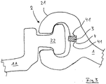
- Fig. 3 finally shows the unswollen sealant 3 in an alternatively configured recess 4, which is designed in the manner of a keyway.
- a sealing tape 3 are inserted or clamped as a sealant.
Landscapes
- Engineering & Computer Science (AREA)
- Structural Engineering (AREA)
- Life Sciences & Earth Sciences (AREA)
- General Life Sciences & Earth Sciences (AREA)
- Mining & Mineral Resources (AREA)
- Paleontology (AREA)
- Civil Engineering (AREA)
- General Engineering & Computer Science (AREA)
- Bulkheads Adapted To Foundation Construction (AREA)
Claims (15)
- Palplanche (1) pour former une paroi de palplanches étanche à l'humidité et composée de plusieurs palplanches (1, 1A) reliés les unes aux autres, un premier élément d'accouplement (21) s'étendant le long du côté longitudinal de la palplanche (1), lequel élément d'accouplement étant adapté à un deuxième élément d'accouplement (22) d'une autre palplanche (1A) de sorte que le premier et le deuxième élément d'accouplement forment ensemble un dispositif de verrouillage de palplanches (2) verrouillé pour obtenir une connexion par engagement positif des palplanches (1, 1A) adjacentes ;
et
une masse d'étanchéité (3) étant prévue dans le premier élément d'accouplement (21) pour rendre le dispositif de verrouillage de palplanches (2) étanche contre l'humidité,
caractérisée en ce que
la masse d'étanchéité (3) est gonflable s'il y a de l'humidité ;
un évidement (4) pour recevoir la masse d'étanchéité est prévu dans le premier élément d'accouplement (21), lequel évidement s'étend le long du premier élément d'accouplement,
l'évidement (4) est rempli de la masse d'étanchéité gonflable (3), de sorte que
si le dispositif de verrouillage de palplanches est verrouillé, la masse d'étanchéité (3A) non gonflée vient en contact avec le deuxième élément de verrouillage (1A) de sorte que le dispositif de verrouillage de palplanches (2) n'est pas étanche contre l'humidité, et de préférence la masse d'étanchéité non gonflée (3) ne peut pas venir en contact avec le deuxième élément de verrouillage (1A), si le dispositif de verrouillage de palplanches est verrouillé, et
si le dispositif de verrouillage de palplanches est verrouillé, la masse d'étanchéité (3A) gonflée vient en contact avec le deuxième élément de verrouillage (1A) de sorte que le dispositif de verrouillage de palplanches (2) est étanche contre l'humidité. - Palplanche selon la revendication 1 ou selon le préambule de la revendication principale, caractérisée en ce que l'extrémité inférieure du premier élément d'accouplement, laquelle se trouve à l'avant dans le sens de battage, comprend une couverture qui couvre la face frontale inférieure de l'agent d'étanchéité, laquelle se trouve à l'avant dans le sens de battage, au moins dans l'état non gonflé.
- Palplanche extrudée (1) pour former une paroi de palplanches étanche à l'humidité et composée de plusieurs palplanches (1, 1A) reliés les unes aux autres,
un premier élément d'accouplement (21) s'étendant le long du côté longitudinal de la palplanche (1), lequel élément d'accouplement étant adapté à un deuxième élément d'accouplement (22) d'une autre palplanche (1A) de sorte que le premier et le deuxième élément d'accouplement forment ensemble un dispositif de verrouillage de palplanches (2) verrouillé pour obtenir une connexion par engagement positif des palplanches (1, 1A) adjacentes ;
et
une masse d'étanchéité (3) étant prévue dans le premier élément d'accouplement (21) pour rendre le dispositif de verrouillage de palplanches (2) étanche contre l'humidité,
caractérisée en ce que
la masse d'étanchéité (3) est gonflable s'il y a de l'humidité ;
dans le premier élément d'accouplement (21), la masse d'étanchéité s'étend le long du premier élément d'accouplement, la masse d'étanchéité étant reliée à la palplanche par coextrusion pendant l'extrusion de celle-ci, par moyen de mélange thermique, de sorte que
si le dispositif de verrouillage de palplanches est verrouillé, la masse d'étanchéité (3A) non gonflée vient en contact avec le deuxième élément de verrouillage (1A) de sorte que le dispositif de verrouillage de palplanches (2) n'est pas étanche contre l'humidité, et de préférence la masse d'étanchéité non gonflée (3) ne peut pas venir en contact avec le deuxième élément de verrouillage (1A), si le dispositif de verrouillage de palplanches est verrouillé, et
si le dispositif de verrouillage de palplanches est verrouillé, la masse d'étanchéité (3A) gonflée vient en contact avec le deuxième élément de verrouillage (1A) de sorte que le dispositif de verrouillage de palplanches (2) est étanche contre l'humidité. - Palplanche selon la revendication 1 ou la revendication 2, caractérisée en ce que l'évidement (4) comprend une contre-depouille (41), qui est notamment configurée comme un profilé plat en forme de T.
- Palplanche selon la revendication 1 ou la revendication 2, caractérisée en ce que la palplanche est extrudée et la masse d'étanchéité est reliée à la palplanche par coextrusion pendant l'extrusion de celle-ci, par moyen de mélange thermique.
- Palplanche selon l'une des revendications précédentes, caractérisée en ce que le premier élément d'accouplement (1) est configuré comme profilé en forme de C pour entourer par complémentarité de formes un épaississement (22) d'un deuxième élément d'accouplement ou pour s'imbriquer dans un autre profilé en forme de C d'un deuxième élément d'accouplement pour former un dispositif de verrouillage de palplanches.
- Palplanche selon l'une des revendications précédentes, caractérisée en ce que le premier élément d'accouplement (21) est configuré comme un épaississement (22) pour être entouré par complémentarité de formes par un deuxième élément d'accouplement qui est notamment configuré comme un profilé en forme de C pour former un dispositif de verrouillage de palplanches.
- Palplanche selon l'une des revendications précédentes, caractérisée en ce que la palplanche (1) est réalisée en une plastique, notamment en une matière polymère ou PVC, aussi sous forme de plastique régénérée ou de matériau neuf, qui est de préférence résistant à l'eau salée, à l'acide et/ou aux rayons UV.
- Palplanche selon l'une des revendications précédentes, caractérisée en ce que la palplanche (1) comprend un noyau en plastique régénérée qui est revêtu d'une plastique non-régénérée.
- Palplanche selon l'une des revendications précédentes, caractérisée en ce que la palplanche (1) comprend deux côtés longitudinaux, et le premier élément d'accouplement s'étend le long de l'un côté longitudinal et le deuxième élément d'accouplement s'étend le long de l'autre côté longitudinal.
- Palplanche selon l'une des revendications précédentes ou comprenant les caractéristiques du préambule de la revendication principale,
caractérisée en ce que
des conducteurs électriques se trouvent le long de la palplanche, notamment le long des côtés longitudinaux de la palplanche, de préférence dans le premier élément d'accouplement et/ou dans la masse d'étanchéité, lesquels conducteurs électriques sont reliés à la masse d'étanchéité de sorte que leur résistance changera, si la masse d'étanchéité est endommagée. - Palplanche selon l'une des revendications précédentes ou comprenant les caractéristiques du préambule de la revendication principale,
caractérisée en ce que
des moyens de détection sont prévus pour détecter une position finale de l'autre palplanche, dans laquelle l'extrémité inférieure du deuxième élément d'accouplement, laquelle se trouve à l'avant dans le sens de battage, parvient à l'extrémité inférieure du premier élément d'accouplement, laquelle se trouve à l'avant dans le sens de battage, si le premier et le deuxième élément d'accouplement forment ensemble le dispositif de verrouillage de palplanches verrouillé. - Palplanche selon l'une des revendications précédentes, caractérisée en ce que
si la palplanche est réalisée en plastique, celle-ci comprend un module d'élasticité E compris entre 1000 et 3000 MPa, de préférence entre 1500 et 2500 MPa, notamment entre 1900 et 2100 MPa ;
elle comprend une résistance à la traction et/ou une limite d'élasticité comprise entre 20 et 60 MPa, de préférence entre 30 et 50 MPa ;
elle comprend une largeur de section transversale comprise entre 250 et 750 mm ;
elle comprend une hauteur comprise entre 100 et 320 mm ; et/ou elle comprend une longueur comprise entre 4 et 6 m ;
et
si la palplanche est réalisée en acier, celle-ci
comprend un module d'élasticité E compris entre 200000 et 220000 MPa, de préférence entre 205000 et 215000 MPa, notamment entre 209000 et 211000 MPa ;
elle comprend une résistance à la traction et/ou une limite d'élasticité comprise entre 240 et 510 MPa, de préférence entre 300 et 450 MPa ;
elle comprend une largeur de section transversale comprise entre 250 et 750 mm ;
elle comprend une hauteur comprise entre 100 et 320 mm ; et/ou elle comprend une longueur comprise entre 4 et 6 m. - Palplanche selon l'une des revendications précédentes, caractérisée en ce que la masse d'étanchéité peut se gonfler de manière réversible, et/ou comprend de la bentonite, du caoutchouc gonflant, de la bande gonflante en polymère ou du caoutchouc gonflable dans des conditions humides.
- Paroi de palplanches étanche à l'humidité comprenant une pluralité de palplanches selon l'une des revendications précédentes, comprenant un joint gonflé dans le dispositif de verrouillage de palplanches.
Priority Applications (1)
| Application Number | Priority Date | Filing Date | Title |
|---|---|---|---|
| EP14164373.4A EP2930274B1 (fr) | 2014-04-11 | 2014-04-11 | Palplanche comprenant une masse d'étanchéité pour former une paroi de palplanches étanche à l'humidité |
Applications Claiming Priority (1)
| Application Number | Priority Date | Filing Date | Title |
|---|---|---|---|
| EP14164373.4A EP2930274B1 (fr) | 2014-04-11 | 2014-04-11 | Palplanche comprenant une masse d'étanchéité pour former une paroi de palplanches étanche à l'humidité |
Publications (2)
| Publication Number | Publication Date |
|---|---|
| EP2930274A1 EP2930274A1 (fr) | 2015-10-14 |
| EP2930274B1 true EP2930274B1 (fr) | 2016-06-01 |
Family
ID=50478302
Family Applications (1)
| Application Number | Title | Priority Date | Filing Date |
|---|---|---|---|
| EP14164373.4A Active EP2930274B1 (fr) | 2014-04-11 | 2014-04-11 | Palplanche comprenant une masse d'étanchéité pour former une paroi de palplanches étanche à l'humidité |
Country Status (1)
| Country | Link |
|---|---|
| EP (1) | EP2930274B1 (fr) |
Cited By (1)
| Publication number | Priority date | Publication date | Assignee | Title |
|---|---|---|---|---|
| DE102022000796A1 (de) | 2022-03-08 | 2023-09-14 | G quadrat GmbH | Erdbauelement und Erdbauinstallation aus wenigstens zwei verbundenen Erdbauelementen |
Families Citing this family (1)
| Publication number | Priority date | Publication date | Assignee | Title |
|---|---|---|---|---|
| CN106256965A (zh) * | 2016-05-24 | 2016-12-28 | 海盐汇祥新型建材科技有限公司 | 一种防渗板桩连接锁扣 |
Family Cites Families (2)
| Publication number | Priority date | Publication date | Assignee | Title |
|---|---|---|---|---|
| LU88397A1 (fr) * | 1993-08-27 | 1995-03-01 | Profilarbed Sa | Procédé pour rendre étanches des assemblages de palplanches, dispositif pour la mise en place du matériau d'étanchement et joint étanche ainsi réalisé |
| GB2367321B (en) * | 2000-09-30 | 2004-03-17 | Corus Uk Ltd | Metal sheet piling |
-
2014
- 2014-04-11 EP EP14164373.4A patent/EP2930274B1/fr active Active
Non-Patent Citations (1)
| Title |
|---|
| None * |
Cited By (1)
| Publication number | Priority date | Publication date | Assignee | Title |
|---|---|---|---|---|
| DE102022000796A1 (de) | 2022-03-08 | 2023-09-14 | G quadrat GmbH | Erdbauelement und Erdbauinstallation aus wenigstens zwei verbundenen Erdbauelementen |
Also Published As
| Publication number | Publication date |
|---|---|
| EP2930274A1 (fr) | 2015-10-14 |
Similar Documents
| Publication | Publication Date | Title |
|---|---|---|
| DE69907752T2 (de) | Verfahren und vorrichtung zum abdichten von fugen oder rissen in hydraulischen werken, beton und mauerwerk | |
| DE60129801T2 (de) | Verfahren zum eintreiben von spundbohlen | |
| DE19807640A1 (de) | Überlaufschutz | |
| DE3710822A1 (de) | Tiefbauwerk in grundwasserfuehrendem erdreich | |
| EP2930274A1 (fr) | Palplanche comprenant une masse d'étanchéité pour former une paroi de palplanches étanche à l'humidité | |
| DE29824577U1 (de) | Deich, Netzstruktur von Fahrzeugreifen und Montageplattform | |
| DE4232290A1 (de) | Verfahren zur Sicherung rutschgefährdeter Massen beim Tunnelbau und Verpreßanker | |
| DE3124622C2 (de) | Einrichtung zum Fördern und Einbringen eines Schachtausbaus und dafür geeigneter Ausbauring | |
| EP2899324B1 (fr) | Système d'étanchéification | |
| DE2712869C2 (de) | Verfahren zum Vermeiden von Wassereinbrüchen in untertägige Hohlräume | |
| EP0628662A2 (fr) | Paroi de palplanches | |
| DE19633934A1 (de) | Kleines Horizontalbohrgerät | |
| DE3543808A1 (de) | Verfahren zur abdichtung von tuebbingen und dichtungsrahmen zur durchfuehrung des verfahrens | |
| EP1108855B1 (fr) | Voûte étanche et autoportante pour l'étanchement des tunnels souterrains | |
| DE19604525C2 (de) | Hochliegende Abdichtungssohle mit Baugrubenumschließung | |
| EP3146156B1 (fr) | Élément de protection destiné à être relié à un élément en béton d'une construction de tunnel présentant un drainage | |
| DE3404074A1 (de) | Verfahren zum herstellen einer schlitzwand aus beton | |
| WO2018050287A1 (fr) | Procédé et utilisation d'une bande couvre-joint pour assurer l'étanchéité de joints | |
| EP0574559A1 (fr) | Procede de prevention du deplacement d'une moulure profilee d'etancheite par rapport a un element de tunnel et moulure profilee d'etancheite produite selon ce procede. | |
| DE10125946B4 (de) | Hochwasserschutzvorrichtung | |
| EP0859183B1 (fr) | Anneau d'étanchéité pour anneaux de puits d'accès | |
| DE102015210374A1 (de) | Fugeneinrichtung für Schlitzwandfugen sowie Verfahren | |
| DE29821624U1 (de) | Verbindungselement für Spundbohlen | |
| DE3727752C2 (fr) | ||
| WO2020007631A1 (fr) | Cuvelage de tunnel composé d'au moins deux éléments en béton |
Legal Events
| Date | Code | Title | Description |
|---|---|---|---|
| PUAI | Public reference made under article 153(3) epc to a published international application that has entered the european phase |
Free format text: ORIGINAL CODE: 0009012 |
|
| AK | Designated contracting states |
Kind code of ref document: A1 Designated state(s): AL AT BE BG CH CY CZ DE DK EE ES FI FR GB GR HR HU IE IS IT LI LT LU LV MC MK MT NL NO PL PT RO RS SE SI SK SM TR |
|
| AX | Request for extension of the european patent |
Extension state: BA ME |
|
| GRAP | Despatch of communication of intention to grant a patent |
Free format text: ORIGINAL CODE: EPIDOSNIGR1 |
|
| 17P | Request for examination filed |
Effective date: 20160105 |
|
| RBV | Designated contracting states (corrected) |
Designated state(s): AL AT BE BG CH CY CZ DE DK EE ES FI FR GB GR HR HU IE IS IT LI LT LU LV MC MK MT NL NO PL PT RO RS SE SI SK SM TR |
|
| INTG | Intention to grant announced |
Effective date: 20160211 |
|
| RIC1 | Information provided on ipc code assigned before grant |
Ipc: E02D 5/14 20060101AFI20160129BHEP |
|
| GRAS | Grant fee paid |
Free format text: ORIGINAL CODE: EPIDOSNIGR3 |
|
| GRAA | (expected) grant |
Free format text: ORIGINAL CODE: 0009210 |
|
| AK | Designated contracting states |
Kind code of ref document: B1 Designated state(s): AL AT BE BG CH CY CZ DE DK EE ES FI FR GB GR HR HU IE IS IT LI LT LU LV MC MK MT NL NO PL PT RO RS SE SI SK SM TR |
|
| REG | Reference to a national code |
Ref country code: GB Ref legal event code: FG4D Free format text: NOT ENGLISH |
|
| REG | Reference to a national code |
Ref country code: CH Ref legal event code: EP Ref country code: AT Ref legal event code: REF Ref document number: 803962 Country of ref document: AT Kind code of ref document: T Effective date: 20160615 |
|
| REG | Reference to a national code |
Ref country code: IE Ref legal event code: FG4D Free format text: LANGUAGE OF EP DOCUMENT: GERMAN |
|
| REG | Reference to a national code |
Ref country code: DE Ref legal event code: R096 Ref document number: 502014000870 Country of ref document: DE |
|
| REG | Reference to a national code |
Ref country code: NL Ref legal event code: FP |
|
| REG | Reference to a national code |
Ref country code: LT Ref legal event code: MG4D |
|
| PG25 | Lapsed in a contracting state [announced via postgrant information from national office to epo] |
Ref country code: FI Free format text: LAPSE BECAUSE OF FAILURE TO SUBMIT A TRANSLATION OF THE DESCRIPTION OR TO PAY THE FEE WITHIN THE PRESCRIBED TIME-LIMIT Effective date: 20160601 Ref country code: LT Free format text: LAPSE BECAUSE OF FAILURE TO SUBMIT A TRANSLATION OF THE DESCRIPTION OR TO PAY THE FEE WITHIN THE PRESCRIBED TIME-LIMIT Effective date: 20160601 Ref country code: NO Free format text: LAPSE BECAUSE OF FAILURE TO SUBMIT A TRANSLATION OF THE DESCRIPTION OR TO PAY THE FEE WITHIN THE PRESCRIBED TIME-LIMIT Effective date: 20160901 |
|
| PG25 | Lapsed in a contracting state [announced via postgrant information from national office to epo] |
Ref country code: HR Free format text: LAPSE BECAUSE OF FAILURE TO SUBMIT A TRANSLATION OF THE DESCRIPTION OR TO PAY THE FEE WITHIN THE PRESCRIBED TIME-LIMIT Effective date: 20160601 Ref country code: GR Free format text: LAPSE BECAUSE OF FAILURE TO SUBMIT A TRANSLATION OF THE DESCRIPTION OR TO PAY THE FEE WITHIN THE PRESCRIBED TIME-LIMIT Effective date: 20160902 Ref country code: SE Free format text: LAPSE BECAUSE OF FAILURE TO SUBMIT A TRANSLATION OF THE DESCRIPTION OR TO PAY THE FEE WITHIN THE PRESCRIBED TIME-LIMIT Effective date: 20160601 Ref country code: RS Free format text: LAPSE BECAUSE OF FAILURE TO SUBMIT A TRANSLATION OF THE DESCRIPTION OR TO PAY THE FEE WITHIN THE PRESCRIBED TIME-LIMIT Effective date: 20160601 Ref country code: LV Free format text: LAPSE BECAUSE OF FAILURE TO SUBMIT A TRANSLATION OF THE DESCRIPTION OR TO PAY THE FEE WITHIN THE PRESCRIBED TIME-LIMIT Effective date: 20160601 Ref country code: ES Free format text: LAPSE BECAUSE OF FAILURE TO SUBMIT A TRANSLATION OF THE DESCRIPTION OR TO PAY THE FEE WITHIN THE PRESCRIBED TIME-LIMIT Effective date: 20160601 |
|
| PG25 | Lapsed in a contracting state [announced via postgrant information from national office to epo] |
Ref country code: CZ Free format text: LAPSE BECAUSE OF FAILURE TO SUBMIT A TRANSLATION OF THE DESCRIPTION OR TO PAY THE FEE WITHIN THE PRESCRIBED TIME-LIMIT Effective date: 20160601 Ref country code: EE Free format text: LAPSE BECAUSE OF FAILURE TO SUBMIT A TRANSLATION OF THE DESCRIPTION OR TO PAY THE FEE WITHIN THE PRESCRIBED TIME-LIMIT Effective date: 20160601 Ref country code: IS Free format text: LAPSE BECAUSE OF FAILURE TO SUBMIT A TRANSLATION OF THE DESCRIPTION OR TO PAY THE FEE WITHIN THE PRESCRIBED TIME-LIMIT Effective date: 20161001 Ref country code: SK Free format text: LAPSE BECAUSE OF FAILURE TO SUBMIT A TRANSLATION OF THE DESCRIPTION OR TO PAY THE FEE WITHIN THE PRESCRIBED TIME-LIMIT Effective date: 20160601 Ref country code: RO Free format text: LAPSE BECAUSE OF FAILURE TO SUBMIT A TRANSLATION OF THE DESCRIPTION OR TO PAY THE FEE WITHIN THE PRESCRIBED TIME-LIMIT Effective date: 20160601 Ref country code: IT Free format text: LAPSE BECAUSE OF FAILURE TO SUBMIT A TRANSLATION OF THE DESCRIPTION OR TO PAY THE FEE WITHIN THE PRESCRIBED TIME-LIMIT Effective date: 20160601 |
|
| PG25 | Lapsed in a contracting state [announced via postgrant information from national office to epo] |
Ref country code: PL Free format text: LAPSE BECAUSE OF FAILURE TO SUBMIT A TRANSLATION OF THE DESCRIPTION OR TO PAY THE FEE WITHIN THE PRESCRIBED TIME-LIMIT Effective date: 20160601 Ref country code: PT Free format text: LAPSE BECAUSE OF FAILURE TO SUBMIT A TRANSLATION OF THE DESCRIPTION OR TO PAY THE FEE WITHIN THE PRESCRIBED TIME-LIMIT Effective date: 20161003 Ref country code: SM Free format text: LAPSE BECAUSE OF FAILURE TO SUBMIT A TRANSLATION OF THE DESCRIPTION OR TO PAY THE FEE WITHIN THE PRESCRIBED TIME-LIMIT Effective date: 20160601 |
|
| REG | Reference to a national code |
Ref country code: DE Ref legal event code: R097 Ref document number: 502014000870 Country of ref document: DE |
|
| PLBE | No opposition filed within time limit |
Free format text: ORIGINAL CODE: 0009261 |
|
| STAA | Information on the status of an ep patent application or granted ep patent |
Free format text: STATUS: NO OPPOSITION FILED WITHIN TIME LIMIT |
|
| 26N | No opposition filed |
Effective date: 20170302 |
|
| PG25 | Lapsed in a contracting state [announced via postgrant information from national office to epo] |
Ref country code: DK Free format text: LAPSE BECAUSE OF FAILURE TO SUBMIT A TRANSLATION OF THE DESCRIPTION OR TO PAY THE FEE WITHIN THE PRESCRIBED TIME-LIMIT Effective date: 20160601 Ref country code: SI Free format text: LAPSE BECAUSE OF FAILURE TO SUBMIT A TRANSLATION OF THE DESCRIPTION OR TO PAY THE FEE WITHIN THE PRESCRIBED TIME-LIMIT Effective date: 20160601 |
|
| REG | Reference to a national code |
Ref country code: CH Ref legal event code: PL |
|
| REG | Reference to a national code |
Ref country code: IE Ref legal event code: MM4A |
|
| REG | Reference to a national code |
Ref country code: FR Ref legal event code: ST Effective date: 20171229 |
|
| PG25 | Lapsed in a contracting state [announced via postgrant information from national office to epo] |
Ref country code: FR Free format text: LAPSE BECAUSE OF NON-PAYMENT OF DUE FEES Effective date: 20170502 Ref country code: MC Free format text: LAPSE BECAUSE OF FAILURE TO SUBMIT A TRANSLATION OF THE DESCRIPTION OR TO PAY THE FEE WITHIN THE PRESCRIBED TIME-LIMIT Effective date: 20160601 |
|
| PG25 | Lapsed in a contracting state [announced via postgrant information from national office to epo] |
Ref country code: LI Free format text: LAPSE BECAUSE OF NON-PAYMENT OF DUE FEES Effective date: 20170430 Ref country code: CH Free format text: LAPSE BECAUSE OF NON-PAYMENT OF DUE FEES Effective date: 20170430 Ref country code: LU Free format text: LAPSE BECAUSE OF NON-PAYMENT OF DUE FEES Effective date: 20170411 |
|
| REG | Reference to a national code |
Ref country code: BE Ref legal event code: MM Effective date: 20170430 |
|
| PG25 | Lapsed in a contracting state [announced via postgrant information from national office to epo] |
Ref country code: IE Free format text: LAPSE BECAUSE OF NON-PAYMENT OF DUE FEES Effective date: 20170411 |
|
| PG25 | Lapsed in a contracting state [announced via postgrant information from national office to epo] |
Ref country code: BE Free format text: LAPSE BECAUSE OF NON-PAYMENT OF DUE FEES Effective date: 20170430 |
|
| PG25 | Lapsed in a contracting state [announced via postgrant information from national office to epo] |
Ref country code: MT Free format text: LAPSE BECAUSE OF FAILURE TO SUBMIT A TRANSLATION OF THE DESCRIPTION OR TO PAY THE FEE WITHIN THE PRESCRIBED TIME-LIMIT Effective date: 20160601 |
|
| PG25 | Lapsed in a contracting state [announced via postgrant information from national office to epo] |
Ref country code: AL Free format text: LAPSE BECAUSE OF FAILURE TO SUBMIT A TRANSLATION OF THE DESCRIPTION OR TO PAY THE FEE WITHIN THE PRESCRIBED TIME-LIMIT Effective date: 20160601 |
|
| GBPC | Gb: european patent ceased through non-payment of renewal fee |
Effective date: 20180411 |
|
| PG25 | Lapsed in a contracting state [announced via postgrant information from national office to epo] |
Ref country code: GB Free format text: LAPSE BECAUSE OF NON-PAYMENT OF DUE FEES Effective date: 20180411 |
|
| PG25 | Lapsed in a contracting state [announced via postgrant information from national office to epo] |
Ref country code: HU Free format text: LAPSE BECAUSE OF FAILURE TO SUBMIT A TRANSLATION OF THE DESCRIPTION OR TO PAY THE FEE WITHIN THE PRESCRIBED TIME-LIMIT; INVALID AB INITIO Effective date: 20140411 |
|
| PG25 | Lapsed in a contracting state [announced via postgrant information from national office to epo] |
Ref country code: BG Free format text: LAPSE BECAUSE OF FAILURE TO SUBMIT A TRANSLATION OF THE DESCRIPTION OR TO PAY THE FEE WITHIN THE PRESCRIBED TIME-LIMIT Effective date: 20160601 |
|
| PG25 | Lapsed in a contracting state [announced via postgrant information from national office to epo] |
Ref country code: CY Free format text: LAPSE BECAUSE OF FAILURE TO SUBMIT A TRANSLATION OF THE DESCRIPTION OR TO PAY THE FEE WITHIN THE PRESCRIBED TIME-LIMIT Effective date: 20160601 |
|
| PG25 | Lapsed in a contracting state [announced via postgrant information from national office to epo] |
Ref country code: MK Free format text: LAPSE BECAUSE OF FAILURE TO SUBMIT A TRANSLATION OF THE DESCRIPTION OR TO PAY THE FEE WITHIN THE PRESCRIBED TIME-LIMIT Effective date: 20160601 |
|
| PG25 | Lapsed in a contracting state [announced via postgrant information from national office to epo] |
Ref country code: TR Free format text: LAPSE BECAUSE OF FAILURE TO SUBMIT A TRANSLATION OF THE DESCRIPTION OR TO PAY THE FEE WITHIN THE PRESCRIBED TIME-LIMIT Effective date: 20160601 |
|
| REG | Reference to a national code |
Ref country code: AT Ref legal event code: MM01 Ref document number: 803962 Country of ref document: AT Kind code of ref document: T Effective date: 20190411 |
|
| PG25 | Lapsed in a contracting state [announced via postgrant information from national office to epo] |
Ref country code: AT Free format text: LAPSE BECAUSE OF NON-PAYMENT OF DUE FEES Effective date: 20190411 |
|
| REG | Reference to a national code |
Ref country code: DE Ref legal event code: R082 Ref document number: 502014000870 Country of ref document: DE Representative=s name: OHRMANN, NIELS, DIPL.-ING., DE |
|
| PGFP | Annual fee paid to national office [announced via postgrant information from national office to epo] |
Ref country code: NL Payment date: 20230413 Year of fee payment: 10 |
|
| P01 | Opt-out of the competence of the unified patent court (upc) registered |
Effective date: 20230602 |
|
| REG | Reference to a national code |
Ref country code: DE Ref legal event code: R081 Ref document number: 502014000870 Country of ref document: DE Owner name: G QUADRAT SOLUTIONS GMBH, DE Free format text: FORMER OWNER: DUBA DEPONIE-UND BAUWERKSABDICHTUNG GMBH, 14823 NIEMEGK, DE Ref country code: DE Ref legal event code: R081 Ref document number: 502014000870 Country of ref document: DE Owner name: G QUADRAT GMBH, DE Free format text: FORMER OWNER: DUBA DEPONIE-UND BAUWERKSABDICHTUNG GMBH, 14823 NIEMEGK, DE |
|
| REG | Reference to a national code |
Ref country code: DE Ref legal event code: R081 Ref document number: 502014000870 Country of ref document: DE Owner name: G QUADRAT GMBH, DE Free format text: FORMER OWNER: G QUADRAT SOLUTIONS GMBH, 06785 ORANIENBAUM-WOERLITZ, DE |
|
| REG | Reference to a national code |
Ref country code: NL Ref legal event code: MM Effective date: 20240501 |
|
| PG25 | Lapsed in a contracting state [announced via postgrant information from national office to epo] |
Ref country code: NL Free format text: LAPSE BECAUSE OF NON-PAYMENT OF DUE FEES Effective date: 20240501 |
|
| PG25 | Lapsed in a contracting state [announced via postgrant information from national office to epo] |
Ref country code: NL Free format text: LAPSE BECAUSE OF NON-PAYMENT OF DUE FEES Effective date: 20240501 |
|
| PGFP | Annual fee paid to national office [announced via postgrant information from national office to epo] |
Ref country code: DE Payment date: 20250430 Year of fee payment: 12 |