EP2930293A2 - Unité de poignée de porte de véhicule automobile dotée d'une caméra - Google Patents
Unité de poignée de porte de véhicule automobile dotée d'une caméra Download PDFInfo
- Publication number
- EP2930293A2 EP2930293A2 EP15000636.9A EP15000636A EP2930293A2 EP 2930293 A2 EP2930293 A2 EP 2930293A2 EP 15000636 A EP15000636 A EP 15000636A EP 2930293 A2 EP2930293 A2 EP 2930293A2
- Authority
- EP
- European Patent Office
- Prior art keywords
- motor vehicle
- camera
- vehicle door
- handle unit
- door handle
- Prior art date
- Legal status (The legal status is an assumption and is not a legal conclusion. Google has not performed a legal analysis and makes no representation as to the accuracy of the status listed.)
- Granted
Links
Images


Classifications
-
- E—FIXED CONSTRUCTIONS
- E05—LOCKS; KEYS; WINDOW OR DOOR FITTINGS; SAFES
- E05B—LOCKS; ACCESSORIES THEREFOR; HANDCUFFS
- E05B85/00—Details of vehicle locks not provided for in groups E05B77/00 - E05B83/00
- E05B85/10—Handles
-
- B—PERFORMING OPERATIONS; TRANSPORTING
- B60—VEHICLES IN GENERAL
- B60R—VEHICLES, VEHICLE FITTINGS, OR VEHICLE PARTS, NOT OTHERWISE PROVIDED FOR
- B60R11/00—Arrangements for holding or mounting articles, not otherwise provided for
- B60R11/04—Mounting of cameras operative during drive; Arrangement of controls thereof relative to the vehicle
-
- B—PERFORMING OPERATIONS; TRANSPORTING
- B60—VEHICLES IN GENERAL
- B60S—SERVICING, CLEANING, REPAIRING, SUPPORTING, LIFTING, OR MANOEUVRING OF VEHICLES, NOT OTHERWISE PROVIDED FOR
- B60S1/00—Cleaning of vehicles
- B60S1/02—Cleaning windscreens, windows or optical devices
- B60S1/46—Cleaning windscreens, windows or optical devices using liquid; Windscreen washers
- B60S1/48—Liquid supply therefor
- B60S1/52—Arrangement of nozzles; Liquid spreading means
- B60S1/522—Arrangement of nozzles; Liquid spreading means moving liquid spreading means, e.g. arranged in wiper arms
- B60S1/528—Arrangement of nozzles; Liquid spreading means moving liquid spreading means, e.g. arranged in wiper arms the spreading means being moved between a rest position and a working position
-
- B—PERFORMING OPERATIONS; TRANSPORTING
- B60—VEHICLES IN GENERAL
- B60S—SERVICING, CLEANING, REPAIRING, SUPPORTING, LIFTING, OR MANOEUVRING OF VEHICLES, NOT OTHERWISE PROVIDED FOR
- B60S1/00—Cleaning of vehicles
- B60S1/02—Cleaning windscreens, windows or optical devices
- B60S1/56—Cleaning windscreens, windows or optical devices specially adapted for cleaning other parts or devices than front windows or windscreens
-
- E—FIXED CONSTRUCTIONS
- E05—LOCKS; KEYS; WINDOW OR DOOR FITTINGS; SAFES
- E05B—LOCKS; ACCESSORIES THEREFOR; HANDCUFFS
- E05B85/00—Details of vehicle locks not provided for in groups E05B77/00 - E05B83/00
- E05B85/10—Handles
- E05B85/103—Handles creating a completely closed wing surface
-
- E—FIXED CONSTRUCTIONS
- E05—LOCKS; KEYS; WINDOW OR DOOR FITTINGS; SAFES
- E05B—LOCKS; ACCESSORIES THEREFOR; HANDCUFFS
- E05B85/00—Details of vehicle locks not provided for in groups E05B77/00 - E05B83/00
- E05B85/10—Handles
- E05B85/107—Pop-out handles, e.g. sliding outwardly before rotation
-
- B—PERFORMING OPERATIONS; TRANSPORTING
- B60—VEHICLES IN GENERAL
- B60R—VEHICLES, VEHICLE FITTINGS, OR VEHICLE PARTS, NOT OTHERWISE PROVIDED FOR
- B60R11/00—Arrangements for holding or mounting articles, not otherwise provided for
- B60R2011/0001—Arrangements for holding or mounting articles, not otherwise provided for characterised by position
- B60R2011/004—Arrangements for holding or mounting articles, not otherwise provided for characterised by position outside the vehicle
-
- B—PERFORMING OPERATIONS; TRANSPORTING
- B60—VEHICLES IN GENERAL
- B60R—VEHICLES, VEHICLE FITTINGS, OR VEHICLE PARTS, NOT OTHERWISE PROVIDED FOR
- B60R11/00—Arrangements for holding or mounting articles, not otherwise provided for
- B60R2011/0094—Arrangements for holding or mounting articles, not otherwise provided for characterised by means for covering after user, e.g. boxes, shutters or the like
Definitions
- the invention relates to a motor vehicle door handle unit with a handle for Mating- and / or door operation of a motor vehicle.
- Such motor vehicle door handle units for door lock and door operation of a motor vehicle are known. Furthermore, it is known to arrange a reversing camera at the rear of a motor vehicle.
- a disadvantage here is the very limited viewing angle of such a camera, with which only a narrow area behind the motor vehicle can be detected, but not the area laterally next to the vehicle.
- the object of the invention is to overcome these disadvantages and to further develop a motor vehicle door handle unit of the type mentioned in the introduction such that it has an extended functionality.
- the motor vehicle door handle unit has at least one camera by means of which an area next to and / or behind the vehicle can be optically detected, wherein the camera is positioned or movable and positionable such that the camera is laterally directed to the motor vehicle to the rear.
- a particular advantage is that by means of such a motor vehicle door handle unit, an exterior mirror of a motor vehicle can be replaced.
- At least one camera is integrated in the motor vehicle door handle unit.
- This camera can be fixed within the motor vehicle door handle unit or arranged to be movable within the motor vehicle door handle unit between several different positions.
- the camera is positioned or movably arranged within the motor vehicle door handle unit and can be positioned so that it faces backwards against the main direction of travel of the motor vehicle, so that the area covered by the camera corresponds to the viewing direction and in particular or at least to the viewing angle, by means of a rearview mirror can be viewed by the driver.
- a rearview mirror of a motor vehicle can be replaced.
- the viewing direction of the camera is accordingly directed laterally along the vehicle flank toward the rear of the vehicle.
- the direction to the rear refers to the orientation of the motor vehicle in which the front of the motor vehicle is arranged in front and the rear of the vehicle behind.
- the camera can be arranged or positioned such that by means of the camera, a viewing angle directed downwards in the direction of a curbside is optically detected laterally and / or that obstacles located by the camera through a viewing direction to the side next to the vehicle are detected can.
- the camera can be arranged correspondingly positioned, wherein the concept of positioning in this sense also includes pivoting the camera about one or more axes relative to the motor vehicle door handle unit. It One or more further cameras may also be integrated into the motor vehicle door handle unit in order to be able to optically detect different viewing directions, wherein one or more cameras may be movable and positionable.
- the motor vehicle door handle unit may have a handle housing and the handle may be arranged in the handle housing.
- a handle housing may be formed as a separate component or formed by a body part of the motor vehicle.
- the invention thus relates to a system of such a motor vehicle door handle unit for door lock and / or door operation of a motor vehicle with a camera integrated therein and an image display device, which is arranged within the motor vehicle in the field of vision of a vehicle driver, in particular in the region of a dashboard in the interior of the motor vehicle , In this case, the images captured by the camera are displayed in real time on the image display device.
- the image display device may be a monitor on which the images captured by the camera are displayed.
- the images acquired by means of the camera can be electronically processed by means of an evaluation unit provided for this purpose, for example having an intensified contrast and / or a residual light amplification or the like. Accordingly, an evaluation unit can be provided.
- the image display device can display icons to assist the driver of the motor vehicle in the sense of an assistance system.
- the camera can be arranged in the handle of the motor vehicle door handle unit. Alternatively or cumulatively, the camera can be arranged in a cylinder tower of the motor vehicle door handle unit. In this case, a camera can be arranged alternatively or cumulatively to a lock cylinder within a cylinder tower of the motor vehicle door handle unit.
- an exterior mirror of a motor vehicle can be replaced by such a motor vehicle door handle unit by displaying the image captured by the camera directly on an image display device in the field of vision of the driver of the motor vehicle.
- Such motor vehicle door handle units can be arranged on both sides of the motor vehicle, so that both the left side mirror and the right side mirror of a motor vehicle can be replaced by such motor vehicle door handle units in conjunction with one or more image display devices in the field of vision of the motor vehicle driver.
- the viewing angle relative to a rear-view camera arranged at the rear of the vehicle is significantly increased, since areas along the flank of the vehicle and / or laterally next to the vehicle can be detected optically.
- the handle closes in a closed position flush with a handle housing and / or a motor vehicle door and / or lies in a handle housing and / or a motor vehicle door and is displaceable in at least a first operating position, in which the handle of the handle housing and / or the motor vehicle door protrudes outward and can be engaged behind, with a manual pulling on the handle in the first operating position, the door lock and / or the door opens.
- the camera can be integrated into the handle and / or be arranged such that the camera is positioned upon displacement of the handle in the first operating position such that by means of the camera an area in the direction behind along the vehicle flank of the motor vehicle can be detected ,
- the handle can be displaced into a second operating position in which an area next to and / or behind the motor vehicle can be detected by means of the camera.
- the camera can be integrated in particular in such motor vehicle door handle units, in which the handle terminates flush with a handle housing and / or a motor vehicle door in the closed position and / or rests in a handle housing and / or a motor vehicle door.
- the camera can be kinematically coupled with the handle. Alternatively, the camera can be moved and positioned independently of the handle.
- the handle housing itself may be formed by a component of the motor vehicle door handle unit or a body part of the motor vehicle.
- the camera can be moved between a rest position and at least one operating position, wherein the camera is positioned in the operating position such that the camera is directed laterally to the motor vehicle against the direction of travel to the rear.
- the term direction of travel while the usual direction of a motor vehicle driver forward towards the front of the motor vehicle is meant accordingly, the camera is laterally directed to the motor vehicle towards the rear of the vehicle, so that the angle and the direction of the Camera is designed such that by means of the camera, the function of a rearview mirror can be replaced.
- the camera is movable between a rest position and a plurality of operating positions, the operating positions being determined as a function of the driving speed of the motor vehicle.
- the viewing angle and / or the viewing direction of the camera can be adapted to the driving speed of the motor vehicle, for example in the form that a lower viewing angle is optically detected by means of the camera at low driving speed.
- the camera may have a variable focal length, the determination of the focal length depending on the direction of travel of the motor vehicle and / or depending on the driving speed of the motor vehicle.
- a distinction between a forward and a reverse drive is possible, since it is helpful for the motor vehicle driver, for example in a reverse drive, to capture a larger viewing angle by means of the camera and to bring on a picture display device within the motor vehicle for display. It is particularly advantageous that the detected by means of the camera area of the driving situation can be adjusted and can be distinguished between slow forward drive, fast forward drive and reverse drive.
- the camera is movable between a rest position and a plurality of operating positions, wherein the camera is moved when driving forward of the motor vehicle in a first operating position and reversing the motor vehicle in a second operating position deviating therefrom.
- the switching on and off of the camera and / or a method of the camera between a rest position and one or more operating positions is coupled to an ignition of the motor vehicle and / or carried out by a manual operation.
- this can be a separate Switch may be provided in the interior of the motor vehicle, for example in the dashboard and / or in the door for manual actuation and for switching on the camera to take the realized with the camera rearview mirror function in operation.
- the switching on and off of the camera and / or a method of the camera is coupled between an idle position and one or more operating positions to an ignition of the motor vehicle, so that the commissioning of the rearview mirror function realized with the camera takes place automatically when the motor vehicle is started.
- the motor vehicle door handle unit has a movable cover, in particular a movable cover, by means of which the camera is covered in a rest position of the camera and / or in a rest position of the movable cover.
- a cleaning device for removing dirt from the camera lens is provided, such as in that a camera lens of the camera is guided along a rubber lip and / or on a brush or vice versa that a rubber lip and / or a brush pass by a camera lens fixed during cleaning to clean the camera lens of dirt.
- the motor vehicle door handle unit has immobile and / or variable flow guide elements for reducing wind noise.
- Such flow guide elements are preferably provided in such embodiments in which the motor vehicle door handle unit has a recessed in the rest position, in particular flush handle, the to move out of the handle housing and / or unfolded into an operating position, wherein in this operating position, the camera can also be used.
- the handle over the handle housing over to the outside, so that flow guidance elements can be arranged to avoid wind noise.
- the motor vehicle door handle unit has a lock cylinder for an emergency release.
- the lock cylinder can be covered by the handle in the rest position.
- a button may be provided by means of which the handle can be manually deflected out of its rest position to make the lock cylinder accessible for an emergency release, for example, in the event that an external identification transmitter has failed to operate a radio-controlled motor vehicle locking system and / or at Failure of the electrical supply of the motor vehicle door handle unit, which means that it does not unlock despite an operation by means of the external identification transmitter.
- the motor vehicle door can still be opened by a mechanical actuation of a lock cylinder for an emergency release.
- the motor vehicle door handle unit and / or the handle can have sensors for detecting the approach of a user and / or for detecting a specific movement of a user.
- the approach of a user can be detected to then trigger an automatic identification of an external identification transmitter, for example, using an RFID communication.
- a specific gesture such as a wiping movement of the user along the motor vehicle door handle unit, can be identified by which, for example, an opening of the motor vehicle door is triggered.
- the motor vehicle door handle unit and / or the handle preferably have lighting means.
- the handle and / or a recessed grip of the motor vehicle door handle unit can be illuminated for the user.
- a Environment lighting done such as lighting the floor next to the vehicle door by means of such lighting means.
- the motor vehicle door handle unit comprises an antenna for near field communication and means for establishing a near field communication connection.
- the motor vehicle door handle unit and / or the handle can have further electronic components and / or electronic modules for processing radio signals, sensor signals and / or for establishing and maintaining a near-field communication connection, by means of which, for example, an adjustment with an external identification transmitter can be performed.
- means may be provided for heating and / or cleaning a camera optics of the camera in order to prevent the deposition of dirt and / or fogging of the camera optics, so that the camera can always be reliably used and a rearview mirror function by the camera in conjunction with a picture display device can be realized in the field of vision of the driver.
- the motor vehicle door handle unit has a cleaning device for removing dirt from the camera, by means of which the camera can be cleaned in a rest position and / or in a first operating position and / or in a second operating position.
- the camera can be cleaned in a first operating position and / or in a second operating position by means of such a cleaning device.
- a cleaning device can be arranged both in a stationary camera and in a movable camera.
- such a cleaning device for removing dirt from the camera is formed by a scraper on which the camera slides during a process of the camera and / or in a method of the scraper along. It can thus be moved either the camera or the scraper are moved or it will both the Camera and the scraper relative to each other, the arrangement is such that the camera, in particular at least the outside of the camera lens slides on the scraper, so that by means of the scraper dirt particles are removed from the camera.
- such a scraper may have one or more rubber lips along which the outer camera lens slides along the camera.
- one or more brushes may be disposed along which the outer camera lens slides along the camera to remove debris from the camera.
- a cleaning device for removing dirt from the camera which is formed by a spraying device, can also be arranged, in particular comprising a movable spray nozzle, by means of which the camera can be cleaned.
- a cleaning liquid such as water or water can be sprayed with a cleaning additive to the camera, in particular the camera optics similar to a windscreen washer system known in vehicles to remove dirt particles from the camera by means of the cleaning liquid.
- a movable spray nozzle can be arranged.
- a spray device can thus be arranged such that a cleaning of the camera in a stationary camera can also be done, as in a movably arranged camera.
- a cleaning by means of such a spraying device can be carried out with the camera movable in the rest position and / or in a first operating position and / or in a second operating position.
- a movable spray nozzle which is extended, for example, only to carry out a cleaning of the camera in an operating position and otherwise retracted in a rest position.
- the cleaning of the camera by means of a cleaning device can be carried out automatically after a certain period of time and / or automatically triggered by an evaluation when, for example by means of the evaluation by evaluating the camera images contamination of the camera has been detected, and / or manually by a user be triggered the motor vehicle.
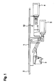
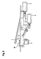
- FIG. 1 shows a side view of a motor vehicle door handle unit in the rest position, in which the handle 1 rests flush in the handle housing 2. It is thus a flush door handle that is flush in its rest position with the vehicle body, that is, with the door, in which the vehicle door handle unit is installed, completes.
- the first servomotor 4 acts translationally on the lever 11, whereby the handle 1 from the closed position according to Fig.1 in a first operating position according to Fig. 2 is displaced around the axis of rotation 12 around.
- the handle 1 In the first operating position according to Fig. 2 the handle 1 is hintergreibar by a user, wherein upon actuation of the handle 1 in the operating position according to Fig. 2 by a user in the case that the motor vehicle locking system is unlocked, the vehicle door can be opened.
- the motor vehicle door handle unit has an antenna for near field communication and means for establishing a near field communication, via which a connection to an external identification transmitter is established via a radio link. If the external identification transmitter supplies the identification associated with the motor vehicle locking system of the motor vehicle via radio, an identification and actuation of the positioning motor 4 takes place automatically, whereby the handle 1 is moved from the rest position according to FIG Fig. 1 in the first operating position According to Fig. 2 is shifted, so that the handle 1 can be taken by the user and the vehicle door can be opened.
- a camera 6 is integrated, whose operation is explained below.
- the servomotor 5 engages the actuating lever 7.
- Fig. 3 shows an intermediate position
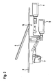
- Fig. 4 shows the moved into a first operating position camera 6, in which the lever 7 has been pivoted by means of the servo motor 5 about the axis 13 so far that the camera 6 was moved to a first operating position.
- the handle 1 is automatically moved into a slightly flared opening position, as in Fig. 4 is shown.
- the first operating position according to Fig. 4 the camera 6 corresponds to that operating position of the camera 6 when driving forward of the motor vehicle. In the position according to Fig.
- the handle 1 is pivoted so far and moved the camera 6 in its first operating position, so that a viewing area in the direction of the arrow 20 along the vehicle flank, in which the Motor vehicle door handle unit is mounted, can be detected by the camera 6 optically.
- the arrow 21 indicates the direction of the vehicle front, that is to say the direction of travel when the vehicle is traveling forwards, and accordingly the arrow 20 indicates the rearward viewing direction along the vehicle flank toward the rear of the vehicle.
- an area optically detectable which corresponds to a viewing angle, which is visible by means of a rearview mirror from the driver, so that by means of the camera 6 in its first operating position, a rearview mirror for a forward drive can be replaced.
- the camera 6 is in a second operating position according to Fig. 5 traversable.
- the actuating lever 7 is further displaced by means of the servo motor 5 by the actuating lever is rotated about the rotation axis 13 and the camera 6 along the slotted guide 14 by a rotational movement about the rotation axis 13 in a translational movement along the slotted guide 14 passes.
- the displacement of the camera from a rest position to one or more operating positions takes place only rotationally and / or translationally or by a sequence of rotational and translational movements.
- a slotted guide can for example also be designed S-shaped, so that counter-rotating movements can follow one another.
- the camera 6 which is guided in a camera carriage 9, moved to the second operating position when reversing the motor vehicle.
- the method of the camera 6 in this second operating position is carried out automatically when engaging the reverse gear in the motor vehicle.
- the operation of the lever 7 by means of the servomotor 5 and the method along the slide guide 14, the camera 6 within the camera slide 9 in the in Fig. 5 illustrated second operating position which makes it possible to detect a wider viewing angle by means of the camera 6, since this when reversing in the direction of arrow 20 of the motor vehicle for the Motor vehicle driver is particularly helpful.
- the focal length of the camera 6 is variable and is adapted to the respective requirement.
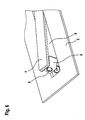
- FIG. 5 shown second operating position of the camera 6 is in Fig. 6 shown in a perspective view. Visible in the illustration according to Fig. 6 is the camera lens 8 of the camera 6 and the carriage 9, within which the camera 6 translationally between the first operating position of the camera 6 according to Fig. 4 and the second operating position of the camera 6 according to FIG Fig. 5 is movable.
- Fig. 7 is a perspective view of the motor vehicle door handle unit with partially opposite the motor vehicle handle housing 2 unfolded handle 1 is shown.
- the lock cylinder 3 is accessible from the outside, to allow an emergency release of the vehicle door, in the event that the electrical systems should have failed, or the external identification transmitter can not send corresponding identification, for example, as a result of a defect.
- a manual operation of the handle 1 is provided, wherein the handle 1 in the open position according to by pressing a corresponding push button Fig. 7 can be displaced, whereby the lock cylinder 3 is accessible to the user and an emergency release of the vehicle door is made possible by pressing the lock cylinder 3 by means of an emergency key.
- brushes are arranged within the handle housing 2, to which the camera lens 8 in the process between the rest position in accordance with Fig. 1 and the operating position of the camera 6 passes and thereby automatically cleaned of dirt.
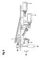
- Fig. 8 shows a side view of a second embodiment of a motor vehicle door handle unit with a cleaning device in the form of a spray nozzle 30, by means of which wash water can be sprayed onto the camera 6 to clean the camera optics of the camera 6 of dirt particles.
- a cleaning device in the form of a spray nozzle 30, by means of which wash water can be sprayed onto the camera 6 to clean the camera optics of the camera 6 of dirt particles.
- the washing water spray device is provided with the spray nozzle 30, by means of which wash water can be sprayed onto the camera 6 to clean the camera 6 of dirt particles. Furthermore, a servomotor 31 is arranged, by means of which the spray nozzle 30 can be moved vertically as indicated by the double arrow 32.
- the spray nozzle 30 In the rest position, the spray nozzle 30 is retracted into the housing of the motor vehicle door handle unit. To actuate the cleaning device, the spray nozzle 30 by means of the servomotor 31 in the in Fig. 8 extended operating position shown and then applied wash water through the spray nozzle 30 to the camera 6.
- the cleaning of the camera 6 by means of the spray nozzle 30 can be triggered manually by the motor vehicle driver when it determines on its image display unit in the motor vehicle that the image quality deteriorates and this is obviously based on contamination of the camera 6.
- any contamination of the camera 6 is automatically detected by an electronic image analysis, whereby an automatic actuation of the spray device is triggered, that is, the extension of the nozzle 30 by means of the servo motor 31 and then the operation of the spray device for cleaning the Camera 6 is triggered automatically.
- Fig. 9 is shown a side view of a third embodiment of a motor vehicle door handle unit with a scraper 40 for cleaning the camera 6. Incidentally, are also in this embodiment according to Fig. 9 again provided with the previous embodiments matching components with identical reference numerals.
- a scraper 40 is fixedly arranged, which is positioned so that the camera 6 when extending into the in Fig. 9 shown operating position on the scraper 40 slides along and thereby the outer lens of the camera 6 is automatically cleaned of dirt particles.
- the scraper 40 has for this purpose a plurality of rubber lips which abut against the outer lens of the camera 6, so that by means of the rubber lips dirt particles are automatically removed from the outer camera lens of the camera 6, when the camera 6 during the process from the rest position into their in Fig. 9 shown operating position slides along the scraper and thereby cleaned. Conversely, during the process, the camera 6 likewise slides back into the rest position within the housing. The operating position along the scraper is thereby cleaned.
Landscapes
- Engineering & Computer Science (AREA)
- Mechanical Engineering (AREA)
- Water Supply & Treatment (AREA)
- Fittings On The Vehicle Exterior For Carrying Loads, And Devices For Holding Or Mounting Articles (AREA)
- Lock And Its Accessories (AREA)
Applications Claiming Priority (2)
| Application Number | Priority Date | Filing Date | Title |
|---|---|---|---|
| DE102014005171 | 2014-04-09 | ||
| DE102014015914.0A DE102014015914A1 (de) | 2014-04-09 | 2014-10-29 | Kraftfahrzeugtürgriffeinheit mit Kamera |
Publications (3)
| Publication Number | Publication Date |
|---|---|
| EP2930293A2 true EP2930293A2 (fr) | 2015-10-14 |
| EP2930293A3 EP2930293A3 (fr) | 2016-05-18 |
| EP2930293B1 EP2930293B1 (fr) | 2018-12-05 |
Family
ID=52807491
Family Applications (1)
| Application Number | Title | Priority Date | Filing Date |
|---|---|---|---|
| EP15000636.9A Active EP2930293B1 (fr) | 2014-04-09 | 2015-03-05 | Unité de poignée de porte de véhicule automobile dotée d'une caméra |
Country Status (2)
| Country | Link |
|---|---|
| EP (1) | EP2930293B1 (fr) |
| DE (1) | DE102014015914A1 (fr) |
Cited By (16)
| Publication number | Priority date | Publication date | Assignee | Title |
|---|---|---|---|---|
| WO2017048126A1 (fr) * | 2015-09-18 | 2017-03-23 | Mci (Mirror Controls International) Netherlands B.V. | Dispositif d'enregistrement d'image mobile et véhicule comportant un tel dispositif |
| WO2017215867A1 (fr) * | 2016-06-13 | 2017-12-21 | Huf Hülsbeck & Fürst Gmbh & Co. Kg | Unité de préhension conçue pour une pièce mobile d'un véhicule |
| US10328906B2 (en) | 2014-04-11 | 2019-06-25 | Dlhbowles, Inc. | Integrated automotive system, compact, low-profile nozzle assembly and compact fluidic circuit for cleaning a wide-angle image sensor's exterior surface |
| US10350647B2 (en) | 2011-03-10 | 2019-07-16 | Dlhbowles, Inc. | Integrated automotive system, nozzle assembly and remote control method for cleaning an image sensor's exterior or objective lens surface |
| DE102018100805A1 (de) * | 2018-01-16 | 2019-07-18 | Connaught Electronics Ltd. | Reinigungsvorrichtung zum Reinigen eines lichtdurchlässigen Frontelements eines optischen Sensors für ein Kraftfahrzeug, Anordnung sowie Verfahren |
| US10432827B2 (en) | 2011-03-10 | 2019-10-01 | Dlhbowles, Inc. | Integrated automotive system, nozzle assembly and remote control method for cleaning an image sensors exterior or objective lens surface |
| DE102018206384A1 (de) * | 2018-04-25 | 2019-10-31 | Bayerische Motoren Werke Aktiengesellschaft | Reinigung von Umfeldsensoren eines Kraftfahrzeugs |
| US10525937B2 (en) | 2014-04-16 | 2020-01-07 | Dlhbowles, Inc. | Integrated multi image sensor and lens washing nozzle assembly and method for simultaneously cleaning a plurality of image sensors |
| EP3505376A4 (fr) * | 2016-08-23 | 2020-04-08 | Alpha Corporation | Dispositif de poignée extérieure de portière de véhicule, portière de véhicule et véhicule |
| CN111071162A (zh) * | 2019-12-10 | 2020-04-28 | 苏州智加科技有限公司 | 传感器安装、拆卸的方法和车辆 |
| WO2021259692A1 (fr) * | 2020-06-24 | 2021-12-30 | Vitesco Technologies GmbH | Dispositif et procédé de surveillance de l'environnement d'un véhicule |
| KR20220030013A (ko) * | 2020-09-02 | 2022-03-10 | 현대모비스 주식회사 | 차량용 후방카메라 및 그 제어방법 |
| CN115534820A (zh) * | 2021-06-14 | 2022-12-30 | 韦巴斯托股份公司 | 具有冷却装置的用于形成车顶的车顶模块 |
| CN116142085A (zh) * | 2021-11-19 | 2023-05-23 | 韦巴斯托股份公司 | 用于安装到机动车面板构件的传感器模块和相关面板构件 |
| CN118187587A (zh) * | 2023-08-10 | 2024-06-14 | 武汉路特斯汽车有限公司 | 一种车门把手的控制方法、控制装置、存储介质及车辆 |
| US12285769B2 (en) | 2021-07-06 | 2025-04-29 | Abc Technologies Inc. | Pulsating spray cleaning nozzle assembly and method |
Families Citing this family (19)
| Publication number | Priority date | Publication date | Assignee | Title |
|---|---|---|---|---|
| DE102016013295A1 (de) | 2016-11-08 | 2017-05-18 | Daimler Ag | Kamerasystem zur Umgebungserfassung |
| DE102017104987A1 (de) | 2017-03-09 | 2018-09-13 | Connaught Electronics Ltd. | Zusätzlicher manueller Antrieb für eine automatisch verstellbare Kameraeinheit |
| EP3437930B1 (fr) | 2017-08-01 | 2021-07-28 | SMR Patents S.à.r.l. | Dispositif de caméra et véhicule automobile comprenant un tel dispositif |
| US11173839B2 (en) | 2017-08-01 | 2021-11-16 | SMR Patents S.à.r.l. | Camera device and motor vehicle therewith |
| CN107503598B (zh) * | 2017-09-30 | 2022-07-15 | 伟速达(中国)汽车安全系统有限公司 | 一种隐藏式汽车外门把手 |
| WO2019158457A1 (fr) * | 2018-02-13 | 2019-08-22 | Inventus Engineering Gmbh | Système de porte comprenant un composant capteur mobile pour reconnaître l'environnement et procédé pour reconnaître l'environnement au niveau d'un système de porte |
| DE102019216122A1 (de) * | 2019-10-21 | 2021-04-22 | Zf Friedrichshafen Ag | Verfahren zur Reinigung einer Sensoreinheit und Reinigungsvorrichtung |
| KR102766134B1 (ko) * | 2020-09-02 | 2025-02-10 | 현대모비스 주식회사 | 차량용 후방카메라 |
| KR102833840B1 (ko) * | 2020-09-02 | 2025-07-11 | 현대모비스 주식회사 | 차량용 후방카메라 |
| KR102740766B1 (ko) * | 2020-09-02 | 2024-12-09 | 현대모비스 주식회사 | 차량용 후방카메라 |
| CN116761736A (zh) * | 2020-12-01 | 2023-09-15 | Tvs电机股份有限公司 | 仪表板控制系统 |
| DE102021117705B4 (de) | 2021-07-08 | 2024-05-29 | Webasto SE | Dachmodul zur Bildung eines Fahrzeugdachs mit einer verstellbaren Reinigungsdüse |
| DE102021122877B4 (de) | 2021-09-03 | 2024-05-29 | Webasto SE | Dachmodul zur Bildung eines Fahrzeugdachs mit einer verstellbaren Reinigungsdüse |
| DE102023000316B4 (de) | 2023-02-02 | 2024-07-11 | Mercedes-Benz Group AG | Fahrzeug und Verfahren zur Reinigung eines Sensors |
| DE102023001359B3 (de) | 2023-04-06 | 2023-12-07 | Mercedes-Benz Group AG | Kameraanordnung für ein Fahrzeug |
| DE102023129469B4 (de) * | 2023-10-25 | 2025-08-07 | Webasto SE | Sensoranordnung mit verstellbarer Sensoreinheit, Fahrzeugdach mit derartiger Sensoranordnung und Kraftfahrzeug mit derartiger Sensoranordnung |
| DE102023131992A1 (de) * | 2023-11-16 | 2025-05-22 | Minebea Accesssolutions Italia S.P.A. | Fahrzeugtür mit einem ausfahrbaren Griff |
| DE102024123061B3 (de) * | 2024-08-13 | 2025-11-13 | Webasto SE | Sensormodul mit Umfeldsensor und Reinigungseinrichtung |
| GB2644028A (en) * | 2024-09-11 | 2026-03-18 | Jaguar Land Rover Ltd | A vehicle camera deployment mechanism |
Family Cites Families (7)
| Publication number | Priority date | Publication date | Assignee | Title |
|---|---|---|---|---|
| WO2001064481A2 (fr) * | 2000-03-02 | 2001-09-07 | Donnelly Corporation | Systeme de miroir video integrant un module accessoire |
| EP1461234B1 (fr) * | 2001-10-01 | 2007-11-07 | Donnelly Corporation | Ensemble poignee de vehicule avec antenne |
| DE102005003786A1 (de) * | 2005-01-19 | 2006-07-20 | Valeo Schalter Und Sensoren Gmbh | Umfelderkennungssystem eines Kraftfahrzeugs |
| DE102007025147B4 (de) * | 2007-05-30 | 2020-08-06 | Bayerische Motoren Werke Aktiengesellschaft | System zur Spurverlassenswarnung und/oder Spurhaltefunktion |
| DE102008008656A1 (de) * | 2008-02-11 | 2009-08-13 | Huf Hülsbeck & Fürst Gmbh & Co. Kg | Kamerasystem für ein Kraftfahrzeug mit einer Kameraeinheit |
| EP2465727B1 (fr) * | 2010-12-15 | 2015-03-25 | SMR Patents S.à.r.l. | Agencement de caméra et poignée de porte pour véhicule à moteur |
| DE102011050471A1 (de) * | 2011-05-18 | 2012-11-22 | Huf Hülsbeck & Fürst Gmbh & Co. Kg | Betätigungsvorrichtung für ein bewegliches Teil eines Kraftfahrzeuges |
-
2014
- 2014-10-29 DE DE102014015914.0A patent/DE102014015914A1/de not_active Withdrawn
-
2015
- 2015-03-05 EP EP15000636.9A patent/EP2930293B1/fr active Active
Non-Patent Citations (1)
| Title |
|---|
| None |
Cited By (29)
| Publication number | Priority date | Publication date | Assignee | Title |
|---|---|---|---|---|
| US10350647B2 (en) | 2011-03-10 | 2019-07-16 | Dlhbowles, Inc. | Integrated automotive system, nozzle assembly and remote control method for cleaning an image sensor's exterior or objective lens surface |
| US10432827B2 (en) | 2011-03-10 | 2019-10-01 | Dlhbowles, Inc. | Integrated automotive system, nozzle assembly and remote control method for cleaning an image sensors exterior or objective lens surface |
| US10328906B2 (en) | 2014-04-11 | 2019-06-25 | Dlhbowles, Inc. | Integrated automotive system, compact, low-profile nozzle assembly and compact fluidic circuit for cleaning a wide-angle image sensor's exterior surface |
| US10525937B2 (en) | 2014-04-16 | 2020-01-07 | Dlhbowles, Inc. | Integrated multi image sensor and lens washing nozzle assembly and method for simultaneously cleaning a plurality of image sensors |
| US11472375B2 (en) | 2014-04-16 | 2022-10-18 | Dlhbowles, Inc. | Integrated multi image sensor and lens washing nozzle assembly and method for simultaneously cleaning a plurality of image sensors |
| US11485294B2 (en) | 2015-09-18 | 2022-11-01 | Mci (Mirror Controls International) Netherlands B.V. | Movable image recording device and vehicle provided with such device |
| WO2017048126A1 (fr) * | 2015-09-18 | 2017-03-23 | Mci (Mirror Controls International) Netherlands B.V. | Dispositif d'enregistrement d'image mobile et véhicule comportant un tel dispositif |
| NL2015468B1 (nl) * | 2015-09-18 | 2017-04-19 | MCI (Mirror Controls International) Netherlands B V | Beweegbare beeldopname inrichting en voertuig voorzien van een dergelijke inrichting. |
| US10343621B2 (en) | 2015-09-18 | 2019-07-09 | Mci (Mirror Controls International) Netherlands B.V. | Movable image recording device and vehicle provided with such device |
| US11097669B2 (en) | 2015-09-18 | 2021-08-24 | Mci (Mirror Controls International) Netherlands B.V. | Movable image recording device and vehicle provided with such device |
| EP3738833A1 (fr) * | 2015-09-18 | 2020-11-18 | MCi (Mirror Controls International) Netherlands B.V. | Dispositif d'enregistrement d'image mobile et véhicule comportant un tel dispositif |
| US10882466B2 (en) | 2015-09-18 | 2021-01-05 | Mci (Mirror Controls International) Netherlands B.V. | Movable image recording device and vehicle provided with such device |
| WO2017215867A1 (fr) * | 2016-06-13 | 2017-12-21 | Huf Hülsbeck & Fürst Gmbh & Co. Kg | Unité de préhension conçue pour une pièce mobile d'un véhicule |
| CN109154169A (zh) * | 2016-06-13 | 2019-01-04 | 胡夫·许尔斯贝克和福斯特有限及两合公司 | 用于车辆的活动部件的把手单元 |
| CN109154169B (zh) * | 2016-06-13 | 2021-05-14 | 胡夫·许尔斯贝克和福斯特有限及两合公司 | 用于车辆的活动部件的把手单元 |
| EP3505376A4 (fr) * | 2016-08-23 | 2020-04-08 | Alpha Corporation | Dispositif de poignée extérieure de portière de véhicule, portière de véhicule et véhicule |
| US10815704B2 (en) | 2016-08-23 | 2020-10-27 | Alpha Corporation | Vehicle door outside handle device, vehicle door, and vehicle |
| EP3957504A1 (fr) * | 2016-08-23 | 2022-02-23 | Alpha Corporation | Dispositif de poignée extérieure de portière de véhicule, portière de véhicule et véhicule |
| DE102018100805A1 (de) * | 2018-01-16 | 2019-07-18 | Connaught Electronics Ltd. | Reinigungsvorrichtung zum Reinigen eines lichtdurchlässigen Frontelements eines optischen Sensors für ein Kraftfahrzeug, Anordnung sowie Verfahren |
| DE102018206384A1 (de) * | 2018-04-25 | 2019-10-31 | Bayerische Motoren Werke Aktiengesellschaft | Reinigung von Umfeldsensoren eines Kraftfahrzeugs |
| CN111071162B (zh) * | 2019-12-10 | 2021-07-30 | 苏州智加科技有限公司 | 传感器安装、拆卸的方法和车辆 |
| CN111071162A (zh) * | 2019-12-10 | 2020-04-28 | 苏州智加科技有限公司 | 传感器安装、拆卸的方法和车辆 |
| WO2021259692A1 (fr) * | 2020-06-24 | 2021-12-30 | Vitesco Technologies GmbH | Dispositif et procédé de surveillance de l'environnement d'un véhicule |
| KR20220030013A (ko) * | 2020-09-02 | 2022-03-10 | 현대모비스 주식회사 | 차량용 후방카메라 및 그 제어방법 |
| CN115534820A (zh) * | 2021-06-14 | 2022-12-30 | 韦巴斯托股份公司 | 具有冷却装置的用于形成车顶的车顶模块 |
| CN115534820B (zh) * | 2021-06-14 | 2025-08-29 | 韦巴斯托股份公司 | 具有冷却装置的用于形成车顶的车顶模块 |
| US12285769B2 (en) | 2021-07-06 | 2025-04-29 | Abc Technologies Inc. | Pulsating spray cleaning nozzle assembly and method |
| CN116142085A (zh) * | 2021-11-19 | 2023-05-23 | 韦巴斯托股份公司 | 用于安装到机动车面板构件的传感器模块和相关面板构件 |
| CN118187587A (zh) * | 2023-08-10 | 2024-06-14 | 武汉路特斯汽车有限公司 | 一种车门把手的控制方法、控制装置、存储介质及车辆 |
Also Published As
| Publication number | Publication date |
|---|---|
| EP2930293B1 (fr) | 2018-12-05 |
| DE102014015914A8 (de) | 2015-12-17 |
| EP2930293A3 (fr) | 2016-05-18 |
| DE102014015914A1 (de) | 2015-10-15 |
Similar Documents
| Publication | Publication Date | Title |
|---|---|---|
| EP2930293B1 (fr) | Unité de poignée de porte de véhicule automobile dotée d'une caméra | |
| EP3717952B1 (fr) | Dispositif conçu pour détecter un environnement et procédé de nettoyage d'un couvercle d'un tel dispositif | |
| EP3230128B1 (fr) | Agencement de camera d'un véhicule automobile | |
| DE102014116681B4 (de) | Fahrzeugintegriertes Sicht- und Reinigungssystem | |
| EP2619039B1 (fr) | Unité de prise de vues pour un véhicule automobile | |
| DE102015115979B4 (de) | Kamerasystem und Fahrzeug | |
| EP3169549B1 (fr) | Unité de caméra pour véhicules automobiles | |
| EP3074278B1 (fr) | Système de caméra de véhicule automobile | |
| DE102010007850A1 (de) | Kameraanordnung zur Überwachung eines Raumes hinter einem Fahrzeugheck | |
| DE102021115326B3 (de) | Dachmodul zur Bildung eines Fahrzeugdachs mit einer Kühleinrichtung | |
| DE112018004812B4 (de) | Aktives Rundumsichtsystem mit Selbstreinigungsmechanismus | |
| WO2010112424A1 (fr) | Dispositif présentant une unité à caméra pour la saisie d'images dans la zone extérieure d'un véhicule à moteur | |
| WO2010029109A1 (fr) | Ensemble modulaire d’acquisition d'images | |
| DE102008012033A1 (de) | Kraftfahrzeug mit einer Kamera | |
| DE102021115335B4 (de) | Dachmodul zur Bildung eines Fahrzeugdachs mit einer Reinigungseinrichtung | |
| DE102005021672A1 (de) | Schutzvorrichtung für eine Kamera eines Kraftfahrzeugs | |
| DE102005021671A1 (de) | Reinigungsvorrichtung für eine Kamera eines Kraftfahrzeugs | |
| DE102011013766A1 (de) | Vorrichtung und ein Verfahren zur Erfassung von Objekten im Schwenkbereich einer Fahrzeugtür | |
| DE102018105657B3 (de) | Rückblicksensoranordnung und fahrzeug | |
| DE102014220713A1 (de) | Verfahren und Vorrichtung zur Verstellung eines Außenspiegels | |
| WO2019219132A1 (fr) | Ensemble capteur, dispositif de nettoyage et couvercle de capteur pour un véhicule à moteur | |
| WO2025067966A1 (fr) | Unité de capteur et véhicule | |
| DE102010005311A1 (de) | Kameraanordnung zur Überwachung eines Raumes hinter einem Fahrzeugheck | |
| DE102022112923A1 (de) | Dachanordnung mit einer Reinigungseinrichtung und Kraftfahrzeug mit einer Reinigungseinrichtung | |
| EP3470272A1 (fr) | Enjoliveur décoratif pour un vehicule et véhicule avec un enjoliveur décoratif |
Legal Events
| Date | Code | Title | Description |
|---|---|---|---|
| PUAI | Public reference made under article 153(3) epc to a published international application that has entered the european phase |
Free format text: ORIGINAL CODE: 0009012 |
|
| AK | Designated contracting states |
Kind code of ref document: A2 Designated state(s): AL AT BE BG CH CY CZ DE DK EE ES FI FR GB GR HR HU IE IS IT LI LT LU LV MC MK MT NL NO PL PT RO RS SE SI SK SM TR |
|
| AX | Request for extension of the european patent |
Extension state: BA ME |
|
| PUAL | Search report despatched |
Free format text: ORIGINAL CODE: 0009013 |
|
| AK | Designated contracting states |
Kind code of ref document: A3 Designated state(s): AL AT BE BG CH CY CZ DE DK EE ES FI FR GB GR HR HU IE IS IT LI LT LU LV MC MK MT NL NO PL PT RO RS SE SI SK SM TR |
|
| AX | Request for extension of the european patent |
Extension state: BA ME |
|
| RIC1 | Information provided on ipc code assigned before grant |
Ipc: B60R 11/04 20060101ALI20160408BHEP Ipc: E05B 85/10 20140101AFI20160408BHEP |
|
| STAA | Information on the status of an ep patent application or granted ep patent |
Free format text: STATUS: REQUEST FOR EXAMINATION WAS MADE |
|
| 17P | Request for examination filed |
Effective date: 20161110 |
|
| RBV | Designated contracting states (corrected) |
Designated state(s): AL AT BE BG CH CY CZ DE DK EE ES FI FR GB GR HR HU IE IS IT LI LT LU LV MC MK MT NL NO PL PT RO RS SE SI SK SM TR |
|
| STAA | Information on the status of an ep patent application or granted ep patent |
Free format text: STATUS: EXAMINATION IS IN PROGRESS |
|
| 17Q | First examination report despatched |
Effective date: 20170517 |
|
| GRAP | Despatch of communication of intention to grant a patent |
Free format text: ORIGINAL CODE: EPIDOSNIGR1 |
|
| STAA | Information on the status of an ep patent application or granted ep patent |
Free format text: STATUS: GRANT OF PATENT IS INTENDED |
|
| INTG | Intention to grant announced |
Effective date: 20180802 |
|
| GRAS | Grant fee paid |
Free format text: ORIGINAL CODE: EPIDOSNIGR3 |
|
| GRAA | (expected) grant |
Free format text: ORIGINAL CODE: 0009210 |
|
| GRAA | (expected) grant |
Free format text: ORIGINAL CODE: 0009210 |
|
| STAA | Information on the status of an ep patent application or granted ep patent |
Free format text: STATUS: THE PATENT HAS BEEN GRANTED |
|
| AK | Designated contracting states |
Kind code of ref document: B1 Designated state(s): AL AT BE BG CH CY CZ DE DK EE ES FI FR GB GR HR HU IE IS IT LI LT LU LV MC MK MT NL NO PL PT RO RS SE SI SK SM TR |
|
| REG | Reference to a national code |
Ref country code: GB Ref legal event code: FG4D Free format text: NOT ENGLISH |
|
| REG | Reference to a national code |
Ref country code: CH Ref legal event code: EP |
|
| REG | Reference to a national code |
Ref country code: AT Ref legal event code: REF Ref document number: 1073285 Country of ref document: AT Kind code of ref document: T Effective date: 20181215 |
|
| REG | Reference to a national code |
Ref country code: IE Ref legal event code: FG4D Free format text: LANGUAGE OF EP DOCUMENT: GERMAN |
|
| REG | Reference to a national code |
Ref country code: DE Ref legal event code: R096 Ref document number: 502015007052 Country of ref document: DE |
|
| REG | Reference to a national code |
Ref country code: NL Ref legal event code: MP Effective date: 20181205 |
|
| REG | Reference to a national code |
Ref country code: LT Ref legal event code: MG4D |
|
| PG25 | Lapsed in a contracting state [announced via postgrant information from national office to epo] |
Ref country code: FI Free format text: LAPSE BECAUSE OF FAILURE TO SUBMIT A TRANSLATION OF THE DESCRIPTION OR TO PAY THE FEE WITHIN THE PRESCRIBED TIME-LIMIT Effective date: 20181205 Ref country code: BG Free format text: LAPSE BECAUSE OF FAILURE TO SUBMIT A TRANSLATION OF THE DESCRIPTION OR TO PAY THE FEE WITHIN THE PRESCRIBED TIME-LIMIT Effective date: 20190305 Ref country code: LV Free format text: LAPSE BECAUSE OF FAILURE TO SUBMIT A TRANSLATION OF THE DESCRIPTION OR TO PAY THE FEE WITHIN THE PRESCRIBED TIME-LIMIT Effective date: 20181205 Ref country code: HR Free format text: LAPSE BECAUSE OF FAILURE TO SUBMIT A TRANSLATION OF THE DESCRIPTION OR TO PAY THE FEE WITHIN THE PRESCRIBED TIME-LIMIT Effective date: 20181205 Ref country code: LT Free format text: LAPSE BECAUSE OF FAILURE TO SUBMIT A TRANSLATION OF THE DESCRIPTION OR TO PAY THE FEE WITHIN THE PRESCRIBED TIME-LIMIT Effective date: 20181205 Ref country code: ES Free format text: LAPSE BECAUSE OF FAILURE TO SUBMIT A TRANSLATION OF THE DESCRIPTION OR TO PAY THE FEE WITHIN THE PRESCRIBED TIME-LIMIT Effective date: 20181205 Ref country code: NO Free format text: LAPSE BECAUSE OF FAILURE TO SUBMIT A TRANSLATION OF THE DESCRIPTION OR TO PAY THE FEE WITHIN THE PRESCRIBED TIME-LIMIT Effective date: 20190305 |
|
| PG25 | Lapsed in a contracting state [announced via postgrant information from national office to epo] |
Ref country code: AL Free format text: LAPSE BECAUSE OF FAILURE TO SUBMIT A TRANSLATION OF THE DESCRIPTION OR TO PAY THE FEE WITHIN THE PRESCRIBED TIME-LIMIT Effective date: 20181205 Ref country code: GR Free format text: LAPSE BECAUSE OF FAILURE TO SUBMIT A TRANSLATION OF THE DESCRIPTION OR TO PAY THE FEE WITHIN THE PRESCRIBED TIME-LIMIT Effective date: 20190306 Ref country code: RS Free format text: LAPSE BECAUSE OF FAILURE TO SUBMIT A TRANSLATION OF THE DESCRIPTION OR TO PAY THE FEE WITHIN THE PRESCRIBED TIME-LIMIT Effective date: 20181205 Ref country code: SE Free format text: LAPSE BECAUSE OF FAILURE TO SUBMIT A TRANSLATION OF THE DESCRIPTION OR TO PAY THE FEE WITHIN THE PRESCRIBED TIME-LIMIT Effective date: 20181205 |
|
| PG25 | Lapsed in a contracting state [announced via postgrant information from national office to epo] |
Ref country code: NL Free format text: LAPSE BECAUSE OF FAILURE TO SUBMIT A TRANSLATION OF THE DESCRIPTION OR TO PAY THE FEE WITHIN THE PRESCRIBED TIME-LIMIT Effective date: 20181205 |
|
| PG25 | Lapsed in a contracting state [announced via postgrant information from national office to epo] |
Ref country code: CZ Free format text: LAPSE BECAUSE OF FAILURE TO SUBMIT A TRANSLATION OF THE DESCRIPTION OR TO PAY THE FEE WITHIN THE PRESCRIBED TIME-LIMIT Effective date: 20181205 Ref country code: PT Free format text: LAPSE BECAUSE OF FAILURE TO SUBMIT A TRANSLATION OF THE DESCRIPTION OR TO PAY THE FEE WITHIN THE PRESCRIBED TIME-LIMIT Effective date: 20190405 Ref country code: PL Free format text: LAPSE BECAUSE OF FAILURE TO SUBMIT A TRANSLATION OF THE DESCRIPTION OR TO PAY THE FEE WITHIN THE PRESCRIBED TIME-LIMIT Effective date: 20181205 |
|
| PG25 | Lapsed in a contracting state [announced via postgrant information from national office to epo] |
Ref country code: EE Free format text: LAPSE BECAUSE OF FAILURE TO SUBMIT A TRANSLATION OF THE DESCRIPTION OR TO PAY THE FEE WITHIN THE PRESCRIBED TIME-LIMIT Effective date: 20181205 Ref country code: SM Free format text: LAPSE BECAUSE OF FAILURE TO SUBMIT A TRANSLATION OF THE DESCRIPTION OR TO PAY THE FEE WITHIN THE PRESCRIBED TIME-LIMIT Effective date: 20181205 Ref country code: SK Free format text: LAPSE BECAUSE OF FAILURE TO SUBMIT A TRANSLATION OF THE DESCRIPTION OR TO PAY THE FEE WITHIN THE PRESCRIBED TIME-LIMIT Effective date: 20181205 Ref country code: IS Free format text: LAPSE BECAUSE OF FAILURE TO SUBMIT A TRANSLATION OF THE DESCRIPTION OR TO PAY THE FEE WITHIN THE PRESCRIBED TIME-LIMIT Effective date: 20190405 Ref country code: RO Free format text: LAPSE BECAUSE OF FAILURE TO SUBMIT A TRANSLATION OF THE DESCRIPTION OR TO PAY THE FEE WITHIN THE PRESCRIBED TIME-LIMIT Effective date: 20181205 |
|
| REG | Reference to a national code |
Ref country code: DE Ref legal event code: R097 Ref document number: 502015007052 Country of ref document: DE |
|
| PLBE | No opposition filed within time limit |
Free format text: ORIGINAL CODE: 0009261 |
|
| STAA | Information on the status of an ep patent application or granted ep patent |
Free format text: STATUS: NO OPPOSITION FILED WITHIN TIME LIMIT |
|
| PG25 | Lapsed in a contracting state [announced via postgrant information from national office to epo] |
Ref country code: SI Free format text: LAPSE BECAUSE OF FAILURE TO SUBMIT A TRANSLATION OF THE DESCRIPTION OR TO PAY THE FEE WITHIN THE PRESCRIBED TIME-LIMIT Effective date: 20181205 Ref country code: MC Free format text: LAPSE BECAUSE OF FAILURE TO SUBMIT A TRANSLATION OF THE DESCRIPTION OR TO PAY THE FEE WITHIN THE PRESCRIBED TIME-LIMIT Effective date: 20181205 Ref country code: DK Free format text: LAPSE BECAUSE OF FAILURE TO SUBMIT A TRANSLATION OF THE DESCRIPTION OR TO PAY THE FEE WITHIN THE PRESCRIBED TIME-LIMIT Effective date: 20181205 |
|
| REG | Reference to a national code |
Ref country code: CH Ref legal event code: PL |
|
| 26N | No opposition filed |
Effective date: 20190906 |
|
| GBPC | Gb: european patent ceased through non-payment of renewal fee |
Effective date: 20190305 |
|
| PG25 | Lapsed in a contracting state [announced via postgrant information from national office to epo] |
Ref country code: LU Free format text: LAPSE BECAUSE OF NON-PAYMENT OF DUE FEES Effective date: 20190305 |
|
| REG | Reference to a national code |
Ref country code: BE Ref legal event code: MM Effective date: 20190331 |
|
| PG25 | Lapsed in a contracting state [announced via postgrant information from national office to epo] |
Ref country code: GB Free format text: LAPSE BECAUSE OF NON-PAYMENT OF DUE FEES Effective date: 20190305 Ref country code: CH Free format text: LAPSE BECAUSE OF NON-PAYMENT OF DUE FEES Effective date: 20190331 Ref country code: IE Free format text: LAPSE BECAUSE OF NON-PAYMENT OF DUE FEES Effective date: 20190305 Ref country code: LI Free format text: LAPSE BECAUSE OF NON-PAYMENT OF DUE FEES Effective date: 20190331 |
|
| PG25 | Lapsed in a contracting state [announced via postgrant information from national office to epo] |
Ref country code: BE Free format text: LAPSE BECAUSE OF NON-PAYMENT OF DUE FEES Effective date: 20190331 |
|
| PG25 | Lapsed in a contracting state [announced via postgrant information from national office to epo] |
Ref country code: TR Free format text: LAPSE BECAUSE OF FAILURE TO SUBMIT A TRANSLATION OF THE DESCRIPTION OR TO PAY THE FEE WITHIN THE PRESCRIBED TIME-LIMIT Effective date: 20181205 |
|
| PG25 | Lapsed in a contracting state [announced via postgrant information from national office to epo] |
Ref country code: MT Free format text: LAPSE BECAUSE OF FAILURE TO SUBMIT A TRANSLATION OF THE DESCRIPTION OR TO PAY THE FEE WITHIN THE PRESCRIBED TIME-LIMIT Effective date: 20181205 |
|
| REG | Reference to a national code |
Ref country code: AT Ref legal event code: MM01 Ref document number: 1073285 Country of ref document: AT Kind code of ref document: T Effective date: 20200305 |
|
| PG25 | Lapsed in a contracting state [announced via postgrant information from national office to epo] |
Ref country code: CY Free format text: LAPSE BECAUSE OF FAILURE TO SUBMIT A TRANSLATION OF THE DESCRIPTION OR TO PAY THE FEE WITHIN THE PRESCRIBED TIME-LIMIT Effective date: 20181205 |
|
| PG25 | Lapsed in a contracting state [announced via postgrant information from national office to epo] |
Ref country code: HU Free format text: LAPSE BECAUSE OF FAILURE TO SUBMIT A TRANSLATION OF THE DESCRIPTION OR TO PAY THE FEE WITHIN THE PRESCRIBED TIME-LIMIT; INVALID AB INITIO Effective date: 20150305 |
|
| PG25 | Lapsed in a contracting state [announced via postgrant information from national office to epo] |
Ref country code: AT Free format text: LAPSE BECAUSE OF NON-PAYMENT OF DUE FEES Effective date: 20200305 |
|
| PG25 | Lapsed in a contracting state [announced via postgrant information from national office to epo] |
Ref country code: MK Free format text: LAPSE BECAUSE OF FAILURE TO SUBMIT A TRANSLATION OF THE DESCRIPTION OR TO PAY THE FEE WITHIN THE PRESCRIBED TIME-LIMIT Effective date: 20181205 |
|
| REG | Reference to a national code |
Ref country code: DE Ref legal event code: R082 Ref document number: 502015007052 Country of ref document: DE Representative=s name: PATENTANWALTSKANZLEI METHLING DR. FRANK-OLIVER, DE Ref country code: DE Ref legal event code: R082 Ref document number: 502015007052 Country of ref document: DE Representative=s name: METHLING, FRANK-OLIVER, DIPL.-ING. DR.-ING., DE |
|
| P01 | Opt-out of the competence of the unified patent court (upc) registered |
Effective date: 20230502 |
|
| PGFP | Annual fee paid to national office [announced via postgrant information from national office to epo] |
Ref country code: IT Payment date: 20230331 Year of fee payment: 9 |
|
| REG | Reference to a national code |
Ref country code: DE Ref legal event code: R082 Ref document number: 502015007052 Country of ref document: DE Representative=s name: METHLING, FRANK-OLIVER, DIPL.-ING. DR.-ING., DE |
|
| PG25 | Lapsed in a contracting state [announced via postgrant information from national office to epo] |
Ref country code: IT Free format text: LAPSE BECAUSE OF NON-PAYMENT OF DUE FEES Effective date: 20240305 |
|
| REG | Reference to a national code |
Ref country code: DE Ref legal event code: R084 Ref document number: 502015007052 Country of ref document: DE |
|
| PGFP | Annual fee paid to national office [announced via postgrant information from national office to epo] |
Ref country code: DE Payment date: 20260331 Year of fee payment: 12 |
|
| PGFP | Annual fee paid to national office [announced via postgrant information from national office to epo] |
Ref country code: FR Payment date: 20260324 Year of fee payment: 12 |