EP2930323B1 - Dispositif permettant de détecter une anomalie pour un purificateur de gaz d'échappement - Google Patents
Dispositif permettant de détecter une anomalie pour un purificateur de gaz d'échappement Download PDFInfo
- Publication number
- EP2930323B1 EP2930323B1 EP12889509.1A EP12889509A EP2930323B1 EP 2930323 B1 EP2930323 B1 EP 2930323B1 EP 12889509 A EP12889509 A EP 12889509A EP 2930323 B1 EP2930323 B1 EP 2930323B1
- Authority
- EP
- European Patent Office
- Prior art keywords
- exhaust gas
- filter
- predetermined
- pressure difference
- gas pressure
- Prior art date
- Legal status (The legal status is an assumption and is not a legal conclusion. Google has not performed a legal analysis and makes no representation as to the accuracy of the status listed.)
- Not-in-force
Links
Images


Classifications
-
- F—MECHANICAL ENGINEERING; LIGHTING; HEATING; WEAPONS; BLASTING
- F01—MACHINES OR ENGINES IN GENERAL; ENGINE PLANTS IN GENERAL; STEAM ENGINES
- F01N—GAS-FLOW SILENCERS OR EXHAUST APPARATUS FOR MACHINES OR ENGINES IN GENERAL; GAS-FLOW SILENCERS OR EXHAUST APPARATUS FOR INTERNAL-COMBUSTION ENGINES
- F01N11/00—Monitoring or diagnostic devices for exhaust-gas treatment apparatus
-
- F—MECHANICAL ENGINEERING; LIGHTING; HEATING; WEAPONS; BLASTING
- F01—MACHINES OR ENGINES IN GENERAL; ENGINE PLANTS IN GENERAL; STEAM ENGINES
- F01N—GAS-FLOW SILENCERS OR EXHAUST APPARATUS FOR MACHINES OR ENGINES IN GENERAL; GAS-FLOW SILENCERS OR EXHAUST APPARATUS FOR INTERNAL-COMBUSTION ENGINES
- F01N13/00—Exhaust or silencing apparatus characterised by constructional features
- F01N13/009—Exhaust or silencing apparatus characterised by constructional features having two or more separate purifying devices arranged in series
-
- F—MECHANICAL ENGINEERING; LIGHTING; HEATING; WEAPONS; BLASTING
- F01—MACHINES OR ENGINES IN GENERAL; ENGINE PLANTS IN GENERAL; STEAM ENGINES
- F01N—GAS-FLOW SILENCERS OR EXHAUST APPARATUS FOR MACHINES OR ENGINES IN GENERAL; GAS-FLOW SILENCERS OR EXHAUST APPARATUS FOR INTERNAL-COMBUSTION ENGINES
- F01N13/00—Exhaust or silencing apparatus characterised by constructional features
- F01N13/009—Exhaust or silencing apparatus characterised by constructional features having two or more separate purifying devices arranged in series
- F01N13/0097—Exhaust or silencing apparatus characterised by constructional features having two or more separate purifying devices arranged in series the purifying devices are arranged in a single housing
-
- F—MECHANICAL ENGINEERING; LIGHTING; HEATING; WEAPONS; BLASTING
- F01—MACHINES OR ENGINES IN GENERAL; ENGINE PLANTS IN GENERAL; STEAM ENGINES
- F01N—GAS-FLOW SILENCERS OR EXHAUST APPARATUS FOR MACHINES OR ENGINES IN GENERAL; GAS-FLOW SILENCERS OR EXHAUST APPARATUS FOR INTERNAL-COMBUSTION ENGINES
- F01N3/00—Exhaust or silencing apparatus having means for purifying, rendering innocuous, or otherwise treating exhaust
- F01N3/02—Exhaust or silencing apparatus having means for purifying, rendering innocuous, or otherwise treating exhaust for cooling, or for removing solid constituents of, exhaust
- F01N3/021—Exhaust or silencing apparatus having means for purifying, rendering innocuous, or otherwise treating exhaust for cooling, or for removing solid constituents of, exhaust by means of filters
-
- F—MECHANICAL ENGINEERING; LIGHTING; HEATING; WEAPONS; BLASTING
- F01—MACHINES OR ENGINES IN GENERAL; ENGINE PLANTS IN GENERAL; STEAM ENGINES
- F01N—GAS-FLOW SILENCERS OR EXHAUST APPARATUS FOR MACHINES OR ENGINES IN GENERAL; GAS-FLOW SILENCERS OR EXHAUST APPARATUS FOR INTERNAL-COMBUSTION ENGINES
- F01N3/00—Exhaust or silencing apparatus having means for purifying, rendering innocuous, or otherwise treating exhaust
- F01N3/02—Exhaust or silencing apparatus having means for purifying, rendering innocuous, or otherwise treating exhaust for cooling, or for removing solid constituents of, exhaust
- F01N3/021—Exhaust or silencing apparatus having means for purifying, rendering innocuous, or otherwise treating exhaust for cooling, or for removing solid constituents of, exhaust by means of filters
- F01N3/023—Exhaust or silencing apparatus having means for purifying, rendering innocuous, or otherwise treating exhaust for cooling, or for removing solid constituents of, exhaust by means of filters using means for regenerating the filters, e.g. by burning trapped particles
-
- F—MECHANICAL ENGINEERING; LIGHTING; HEATING; WEAPONS; BLASTING
- F01—MACHINES OR ENGINES IN GENERAL; ENGINE PLANTS IN GENERAL; STEAM ENGINES
- F01N—GAS-FLOW SILENCERS OR EXHAUST APPARATUS FOR MACHINES OR ENGINES IN GENERAL; GAS-FLOW SILENCERS OR EXHAUST APPARATUS FOR INTERNAL-COMBUSTION ENGINES
- F01N3/00—Exhaust or silencing apparatus having means for purifying, rendering innocuous, or otherwise treating exhaust
- F01N3/02—Exhaust or silencing apparatus having means for purifying, rendering innocuous, or otherwise treating exhaust for cooling, or for removing solid constituents of, exhaust
- F01N3/021—Exhaust or silencing apparatus having means for purifying, rendering innocuous, or otherwise treating exhaust for cooling, or for removing solid constituents of, exhaust by means of filters
- F01N3/023—Exhaust or silencing apparatus having means for purifying, rendering innocuous, or otherwise treating exhaust for cooling, or for removing solid constituents of, exhaust by means of filters using means for regenerating the filters, e.g. by burning trapped particles
- F01N3/025—Exhaust or silencing apparatus having means for purifying, rendering innocuous, or otherwise treating exhaust for cooling, or for removing solid constituents of, exhaust by means of filters using means for regenerating the filters, e.g. by burning trapped particles using fuel burner or by adding fuel to exhaust
-
- F—MECHANICAL ENGINEERING; LIGHTING; HEATING; WEAPONS; BLASTING
- F01—MACHINES OR ENGINES IN GENERAL; ENGINE PLANTS IN GENERAL; STEAM ENGINES
- F01N—GAS-FLOW SILENCERS OR EXHAUST APPARATUS FOR MACHINES OR ENGINES IN GENERAL; GAS-FLOW SILENCERS OR EXHAUST APPARATUS FOR INTERNAL-COMBUSTION ENGINES
- F01N3/00—Exhaust or silencing apparatus having means for purifying, rendering innocuous, or otherwise treating exhaust
- F01N3/02—Exhaust or silencing apparatus having means for purifying, rendering innocuous, or otherwise treating exhaust for cooling, or for removing solid constituents of, exhaust
- F01N3/021—Exhaust or silencing apparatus having means for purifying, rendering innocuous, or otherwise treating exhaust for cooling, or for removing solid constituents of, exhaust by means of filters
- F01N3/033—Exhaust or silencing apparatus having means for purifying, rendering innocuous, or otherwise treating exhaust for cooling, or for removing solid constituents of, exhaust by means of filters in combination with other devices
- F01N3/035—Exhaust or silencing apparatus having means for purifying, rendering innocuous, or otherwise treating exhaust for cooling, or for removing solid constituents of, exhaust by means of filters in combination with other devices with catalytic reactors
-
- F—MECHANICAL ENGINEERING; LIGHTING; HEATING; WEAPONS; BLASTING
- F01—MACHINES OR ENGINES IN GENERAL; ENGINE PLANTS IN GENERAL; STEAM ENGINES
- F01N—GAS-FLOW SILENCERS OR EXHAUST APPARATUS FOR MACHINES OR ENGINES IN GENERAL; GAS-FLOW SILENCERS OR EXHAUST APPARATUS FOR INTERNAL-COMBUSTION ENGINES
- F01N3/00—Exhaust or silencing apparatus having means for purifying, rendering innocuous, or otherwise treating exhaust
- F01N3/08—Exhaust or silencing apparatus having means for purifying, rendering innocuous, or otherwise treating exhaust for rendering innocuous
- F01N3/10—Exhaust or silencing apparatus having means for purifying, rendering innocuous, or otherwise treating exhaust for rendering innocuous by thermal or catalytic conversion of noxious components of exhaust
- F01N3/103—Oxidation catalysts for HC and CO only
-
- F—MECHANICAL ENGINEERING; LIGHTING; HEATING; WEAPONS; BLASTING
- F01—MACHINES OR ENGINES IN GENERAL; ENGINE PLANTS IN GENERAL; STEAM ENGINES
- F01N—GAS-FLOW SILENCERS OR EXHAUST APPARATUS FOR MACHINES OR ENGINES IN GENERAL; GAS-FLOW SILENCERS OR EXHAUST APPARATUS FOR INTERNAL-COMBUSTION ENGINES
- F01N3/00—Exhaust or silencing apparatus having means for purifying, rendering innocuous, or otherwise treating exhaust
- F01N3/08—Exhaust or silencing apparatus having means for purifying, rendering innocuous, or otherwise treating exhaust for rendering innocuous
- F01N3/10—Exhaust or silencing apparatus having means for purifying, rendering innocuous, or otherwise treating exhaust for rendering innocuous by thermal or catalytic conversion of noxious components of exhaust
- F01N3/18—Exhaust or silencing apparatus having means for purifying, rendering innocuous, or otherwise treating exhaust for rendering innocuous by thermal or catalytic conversion of noxious components of exhaust characterised by methods of operation; Control
- F01N3/20—Exhaust or silencing apparatus having means for purifying, rendering innocuous, or otherwise treating exhaust for rendering innocuous by thermal or catalytic conversion of noxious components of exhaust characterised by methods of operation; Control specially adapted for catalytic conversion
- F01N3/206—Adding periodically or continuously substances to exhaust gases for promoting purification, e.g. catalytic material in liquid form, NOx reducing agents
- F01N3/2066—Selective catalytic reduction [SCR]
-
- F—MECHANICAL ENGINEERING; LIGHTING; HEATING; WEAPONS; BLASTING
- F01—MACHINES OR ENGINES IN GENERAL; ENGINE PLANTS IN GENERAL; STEAM ENGINES
- F01N—GAS-FLOW SILENCERS OR EXHAUST APPARATUS FOR MACHINES OR ENGINES IN GENERAL; GAS-FLOW SILENCERS OR EXHAUST APPARATUS FOR INTERNAL-COMBUSTION ENGINES
- F01N3/00—Exhaust or silencing apparatus having means for purifying, rendering innocuous, or otherwise treating exhaust
- F01N3/08—Exhaust or silencing apparatus having means for purifying, rendering innocuous, or otherwise treating exhaust for rendering innocuous
- F01N3/10—Exhaust or silencing apparatus having means for purifying, rendering innocuous, or otherwise treating exhaust for rendering innocuous by thermal or catalytic conversion of noxious components of exhaust
- F01N3/18—Exhaust or silencing apparatus having means for purifying, rendering innocuous, or otherwise treating exhaust for rendering innocuous by thermal or catalytic conversion of noxious components of exhaust characterised by methods of operation; Control
- F01N3/20—Exhaust or silencing apparatus having means for purifying, rendering innocuous, or otherwise treating exhaust for rendering innocuous by thermal or catalytic conversion of noxious components of exhaust characterised by methods of operation; Control specially adapted for catalytic conversion
- F01N3/206—Adding periodically or continuously substances to exhaust gases for promoting purification, e.g. catalytic material in liquid form, NOx reducing agents
- F01N3/208—Control of selective catalytic reduction [SCR], e.g. by adjusting the dosing of reducing agent
-
- F—MECHANICAL ENGINEERING; LIGHTING; HEATING; WEAPONS; BLASTING
- F01—MACHINES OR ENGINES IN GENERAL; ENGINE PLANTS IN GENERAL; STEAM ENGINES
- F01N—GAS-FLOW SILENCERS OR EXHAUST APPARATUS FOR MACHINES OR ENGINES IN GENERAL; GAS-FLOW SILENCERS OR EXHAUST APPARATUS FOR INTERNAL-COMBUSTION ENGINES
- F01N3/00—Exhaust or silencing apparatus having means for purifying, rendering innocuous, or otherwise treating exhaust
- F01N3/08—Exhaust or silencing apparatus having means for purifying, rendering innocuous, or otherwise treating exhaust for rendering innocuous
- F01N3/10—Exhaust or silencing apparatus having means for purifying, rendering innocuous, or otherwise treating exhaust for rendering innocuous by thermal or catalytic conversion of noxious components of exhaust
- F01N3/24—Exhaust or silencing apparatus having means for purifying, rendering innocuous, or otherwise treating exhaust for rendering innocuous by thermal or catalytic conversion of noxious components of exhaust characterised by constructional aspects of converting apparatus
- F01N3/28—Construction of catalytic reactors
- F01N3/2892—Exhaust flow directors or the like, e.g. upstream of catalytic device
-
- F—MECHANICAL ENGINEERING; LIGHTING; HEATING; WEAPONS; BLASTING
- F01—MACHINES OR ENGINES IN GENERAL; ENGINE PLANTS IN GENERAL; STEAM ENGINES
- F01N—GAS-FLOW SILENCERS OR EXHAUST APPARATUS FOR MACHINES OR ENGINES IN GENERAL; GAS-FLOW SILENCERS OR EXHAUST APPARATUS FOR INTERNAL-COMBUSTION ENGINES
- F01N9/00—Electrical control of exhaust gas treating apparatus
-
- F—MECHANICAL ENGINEERING; LIGHTING; HEATING; WEAPONS; BLASTING
- F01—MACHINES OR ENGINES IN GENERAL; ENGINE PLANTS IN GENERAL; STEAM ENGINES
- F01N—GAS-FLOW SILENCERS OR EXHAUST APPARATUS FOR MACHINES OR ENGINES IN GENERAL; GAS-FLOW SILENCERS OR EXHAUST APPARATUS FOR INTERNAL-COMBUSTION ENGINES
- F01N2240/00—Combination or association of two or more different exhaust treating devices, or of at least one such device with an auxiliary device, not covered by indexing codes F01N2230/00 or F01N2250/00, one of the devices being
- F01N2240/20—Combination or association of two or more different exhaust treating devices, or of at least one such device with an auxiliary device, not covered by indexing codes F01N2230/00 or F01N2250/00, one of the devices being a flow director or deflector
-
- F—MECHANICAL ENGINEERING; LIGHTING; HEATING; WEAPONS; BLASTING
- F01—MACHINES OR ENGINES IN GENERAL; ENGINE PLANTS IN GENERAL; STEAM ENGINES
- F01N—GAS-FLOW SILENCERS OR EXHAUST APPARATUS FOR MACHINES OR ENGINES IN GENERAL; GAS-FLOW SILENCERS OR EXHAUST APPARATUS FOR INTERNAL-COMBUSTION ENGINES
- F01N2250/00—Combinations of different methods of purification
- F01N2250/02—Combinations of different methods of purification filtering and catalytic conversion
-
- F—MECHANICAL ENGINEERING; LIGHTING; HEATING; WEAPONS; BLASTING
- F01—MACHINES OR ENGINES IN GENERAL; ENGINE PLANTS IN GENERAL; STEAM ENGINES
- F01N—GAS-FLOW SILENCERS OR EXHAUST APPARATUS FOR MACHINES OR ENGINES IN GENERAL; GAS-FLOW SILENCERS OR EXHAUST APPARATUS FOR INTERNAL-COMBUSTION ENGINES
- F01N2550/00—Monitoring or diagnosing the deterioration of exhaust systems
- F01N2550/02—Catalytic activity of catalytic converters
-
- F—MECHANICAL ENGINEERING; LIGHTING; HEATING; WEAPONS; BLASTING
- F01—MACHINES OR ENGINES IN GENERAL; ENGINE PLANTS IN GENERAL; STEAM ENGINES
- F01N—GAS-FLOW SILENCERS OR EXHAUST APPARATUS FOR MACHINES OR ENGINES IN GENERAL; GAS-FLOW SILENCERS OR EXHAUST APPARATUS FOR INTERNAL-COMBUSTION ENGINES
- F01N2550/00—Monitoring or diagnosing the deterioration of exhaust systems
- F01N2550/04—Filtering activity of particulate filters
-
- F—MECHANICAL ENGINEERING; LIGHTING; HEATING; WEAPONS; BLASTING
- F01—MACHINES OR ENGINES IN GENERAL; ENGINE PLANTS IN GENERAL; STEAM ENGINES
- F01N—GAS-FLOW SILENCERS OR EXHAUST APPARATUS FOR MACHINES OR ENGINES IN GENERAL; GAS-FLOW SILENCERS OR EXHAUST APPARATUS FOR INTERNAL-COMBUSTION ENGINES
- F01N2550/00—Monitoring or diagnosing the deterioration of exhaust systems
- F01N2550/05—Systems for adding substances into exhaust
-
- F—MECHANICAL ENGINEERING; LIGHTING; HEATING; WEAPONS; BLASTING
- F01—MACHINES OR ENGINES IN GENERAL; ENGINE PLANTS IN GENERAL; STEAM ENGINES
- F01N—GAS-FLOW SILENCERS OR EXHAUST APPARATUS FOR MACHINES OR ENGINES IN GENERAL; GAS-FLOW SILENCERS OR EXHAUST APPARATUS FOR INTERNAL-COMBUSTION ENGINES
- F01N2560/00—Exhaust systems with means for detecting or measuring exhaust gas components or characteristics
- F01N2560/02—Exhaust systems with means for detecting or measuring exhaust gas components or characteristics the means being an exhaust gas sensor
- F01N2560/026—Exhaust systems with means for detecting or measuring exhaust gas components or characteristics the means being an exhaust gas sensor for measuring or detecting NOx
-
- F—MECHANICAL ENGINEERING; LIGHTING; HEATING; WEAPONS; BLASTING
- F01—MACHINES OR ENGINES IN GENERAL; ENGINE PLANTS IN GENERAL; STEAM ENGINES
- F01N—GAS-FLOW SILENCERS OR EXHAUST APPARATUS FOR MACHINES OR ENGINES IN GENERAL; GAS-FLOW SILENCERS OR EXHAUST APPARATUS FOR INTERNAL-COMBUSTION ENGINES
- F01N2560/00—Exhaust systems with means for detecting or measuring exhaust gas components or characteristics
- F01N2560/05—Exhaust systems with means for detecting or measuring exhaust gas components or characteristics the means being a particulate sensor
-
- F—MECHANICAL ENGINEERING; LIGHTING; HEATING; WEAPONS; BLASTING
- F01—MACHINES OR ENGINES IN GENERAL; ENGINE PLANTS IN GENERAL; STEAM ENGINES
- F01N—GAS-FLOW SILENCERS OR EXHAUST APPARATUS FOR MACHINES OR ENGINES IN GENERAL; GAS-FLOW SILENCERS OR EXHAUST APPARATUS FOR INTERNAL-COMBUSTION ENGINES
- F01N2560/00—Exhaust systems with means for detecting or measuring exhaust gas components or characteristics
- F01N2560/07—Exhaust systems with means for detecting or measuring exhaust gas components or characteristics the means being an exhaust gas flow rate or velocity meter or sensor, intake flow meters only when exclusively used to determine exhaust gas parameters
-
- F—MECHANICAL ENGINEERING; LIGHTING; HEATING; WEAPONS; BLASTING
- F01—MACHINES OR ENGINES IN GENERAL; ENGINE PLANTS IN GENERAL; STEAM ENGINES
- F01N—GAS-FLOW SILENCERS OR EXHAUST APPARATUS FOR MACHINES OR ENGINES IN GENERAL; GAS-FLOW SILENCERS OR EXHAUST APPARATUS FOR INTERNAL-COMBUSTION ENGINES
- F01N2560/00—Exhaust systems with means for detecting or measuring exhaust gas components or characteristics
- F01N2560/08—Exhaust systems with means for detecting or measuring exhaust gas components or characteristics the means being a pressure sensor
-
- F—MECHANICAL ENGINEERING; LIGHTING; HEATING; WEAPONS; BLASTING
- F01—MACHINES OR ENGINES IN GENERAL; ENGINE PLANTS IN GENERAL; STEAM ENGINES
- F01N—GAS-FLOW SILENCERS OR EXHAUST APPARATUS FOR MACHINES OR ENGINES IN GENERAL; GAS-FLOW SILENCERS OR EXHAUST APPARATUS FOR INTERNAL-COMBUSTION ENGINES
- F01N2610/00—Adding substances to exhaust gases
- F01N2610/02—Adding substances to exhaust gases the substance being ammonia or urea
-
- F—MECHANICAL ENGINEERING; LIGHTING; HEATING; WEAPONS; BLASTING
- F01—MACHINES OR ENGINES IN GENERAL; ENGINE PLANTS IN GENERAL; STEAM ENGINES
- F01N—GAS-FLOW SILENCERS OR EXHAUST APPARATUS FOR MACHINES OR ENGINES IN GENERAL; GAS-FLOW SILENCERS OR EXHAUST APPARATUS FOR INTERNAL-COMBUSTION ENGINES
- F01N2900/00—Details of electrical control or of the monitoring of the exhaust gas treating apparatus
- F01N2900/06—Parameters used for exhaust control or diagnosing
- F01N2900/14—Parameters used for exhaust control or diagnosing said parameters being related to the exhaust gas
- F01N2900/1406—Exhaust gas pressure
-
- F—MECHANICAL ENGINEERING; LIGHTING; HEATING; WEAPONS; BLASTING
- F01—MACHINES OR ENGINES IN GENERAL; ENGINE PLANTS IN GENERAL; STEAM ENGINES
- F01N—GAS-FLOW SILENCERS OR EXHAUST APPARATUS FOR MACHINES OR ENGINES IN GENERAL; GAS-FLOW SILENCERS OR EXHAUST APPARATUS FOR INTERNAL-COMBUSTION ENGINES
- F01N2900/00—Details of electrical control or of the monitoring of the exhaust gas treating apparatus
- F01N2900/06—Parameters used for exhaust control or diagnosing
- F01N2900/16—Parameters used for exhaust control or diagnosing said parameters being related to the exhaust apparatus, e.g. particulate filter or catalyst
- F01N2900/1606—Particle filter loading or soot amount
-
- F—MECHANICAL ENGINEERING; LIGHTING; HEATING; WEAPONS; BLASTING
- F01—MACHINES OR ENGINES IN GENERAL; ENGINE PLANTS IN GENERAL; STEAM ENGINES
- F01N—GAS-FLOW SILENCERS OR EXHAUST APPARATUS FOR MACHINES OR ENGINES IN GENERAL; GAS-FLOW SILENCERS OR EXHAUST APPARATUS FOR INTERNAL-COMBUSTION ENGINES
- F01N2900/00—Details of electrical control or of the monitoring of the exhaust gas treating apparatus
- F01N2900/06—Parameters used for exhaust control or diagnosing
- F01N2900/16—Parameters used for exhaust control or diagnosing said parameters being related to the exhaust apparatus, e.g. particulate filter or catalyst
- F01N2900/1621—Catalyst conversion efficiency
-
- Y—GENERAL TAGGING OF NEW TECHNOLOGICAL DEVELOPMENTS; GENERAL TAGGING OF CROSS-SECTIONAL TECHNOLOGIES SPANNING OVER SEVERAL SECTIONS OF THE IPC; TECHNICAL SUBJECTS COVERED BY FORMER USPC CROSS-REFERENCE ART COLLECTIONS [XRACs] AND DIGESTS
- Y02—TECHNOLOGIES OR APPLICATIONS FOR MITIGATION OR ADAPTATION AGAINST CLIMATE CHANGE
- Y02T—CLIMATE CHANGE MITIGATION TECHNOLOGIES RELATED TO TRANSPORTATION
- Y02T10/00—Road transport of goods or passengers
- Y02T10/10—Internal combustion engine [ICE] based vehicles
- Y02T10/12—Improving ICE efficiencies
-
- Y—GENERAL TAGGING OF NEW TECHNOLOGICAL DEVELOPMENTS; GENERAL TAGGING OF CROSS-SECTIONAL TECHNOLOGIES SPANNING OVER SEVERAL SECTIONS OF THE IPC; TECHNICAL SUBJECTS COVERED BY FORMER USPC CROSS-REFERENCE ART COLLECTIONS [XRACs] AND DIGESTS
- Y02—TECHNOLOGIES OR APPLICATIONS FOR MITIGATION OR ADAPTATION AGAINST CLIMATE CHANGE
- Y02T—CLIMATE CHANGE MITIGATION TECHNOLOGIES RELATED TO TRANSPORTATION
- Y02T10/00—Road transport of goods or passengers
- Y02T10/10—Internal combustion engine [ICE] based vehicles
- Y02T10/40—Engine management systems
Definitions
- the present invention relates to an abnormality detection device for detecting an abnormality (abnormal situation or malfunction) of an exhaust gas purification apparatus for an internal combustion engine.
- a filter is provided as an exhaust gas purification apparatus for an exhaust gas passage of an internal combustion engine in some cases.
- the filter traps the particulate matter (hereinafter referred to as "PM") contained in the exhaust gas.
- Patent Literature 1 discloses a system in which a pressure difference sensor (differential pressure sensor) is provided for outputting a signal corresponding to a difference between the exhaust gas pressure provided on the upstream side from a filter and the exhaust gas pressure provided on the downstream side from the filter (pressure difference between the front and the back of the filter).
- the pressure difference sensor is connected via a pressure introducing tube to the exhaust gas passage on the upstream side from the filter and the exhaust gas passage on the downstream side from the filter. Then, the PM accumulation amount accumulated on the filter is estimated by utilizing the output of the pressure difference sensor.
- Patent Document 1 discloses a technique in which the state of the filter is detected by using the amount of change of the pressure in an intake manifold and the amount of change of the pressure difference between the front and the back of the filter.
- a filter in which a selective catalytic reduction NOx catalyst (hereinafter referred to as "SCR catalyst”) is carried thereon.
- SCR catalyst selective catalytic reduction NOx catalyst
- SCRF selective catalytic reduction NOx catalyst
- Patent Literature 2 discloses a system in which an aqueous urea solution is supplied via a nozzle from the upstream side to SCRF provided for an exhaust gas passage. In this case, urea is hydrolyzed, and thus ammonia is produced. Then, NOx is reduced by an SCR catalyst by using ammonia as a reducing agent. Further, in Patent Literature 2, a pressure difference sensor is provided for detecting the pressure difference between the front and the back of SCRF.
- Patent Literature 3 discloses an abnormality detection device for the clogging defect of a particulate filter in combination with an upstream SCR catalyst, in which the diagnosis is based on a temperature and a pressure difference detection upstream and downstream of the filter and the differences are compared to limit values.
- a reducing agent addition valve which adds the reducing agent into the exhaust gas, is provided on the upstream side from SCRF in the exhaust gas passage.
- the reducing agent which is added from the reducing agent addition valve, flows into SCRF together with the exhaust gas, and thus the reducing agent is supplied to the SCR catalyst carried on SCRF.
- a diffusing device for diffusing the reducing agent is provided for the exhaust gas passage between the reducing agent addition valve and SCRF in some cases.
- An object of the present invention is to distinguish and detect an abnormality of SCRF and an abnormality of a diffusing device in a system in which a diffusing device is provided for an exhaust gas passage between a reducing agent addition valve and SCRF as described above.
- the present invention it is judged that which one of abnormalities of any breakage of SCRF, any clogging-up of SCRF caused by PM, and any abnormality of a diffusing device occurs, on the basis of at least any one of a difference between a NOx purification rate of an SCR catalyst carried on SCRF and a predetermined NOx purification rate and a difference between a PM amount flowing out from SCRF and a predetermined outflow PM amount, when a difference, which is provided between an exhaust gas pressure difference as a difference between an exhaust gas pressure on an upstream side from a reducing agent addition valve and an exhaust gas pressure on a downstream side from SCRF and a predetermined exhaust gas pressure difference, exceeds a certain amount.
- an abnormality detection device for an exhaust gas purification apparatus for detecting an abnormality of the exhaust gas purification apparatus comprising:
- the exhaust gas pressure difference which is the difference between the exhaust gas pressure on the upstream side from the reducing agent addition valve and the exhaust gas pressure on the downstream side from SCRF, is greatly changed as compared with that provided in the normal state. Further, if the abnormality as described above occurs, the values of the NOx purification rate of the SCR catalyst carried on SCRF (hereinafter simply referred to as "NOx purification rate” in some cases) and the PM amount flowing out from SCRF (hereinafter referred to as "outflow PM amount” in some cases) behave in a manner depending on the content of the abnormality.
- NOx purification rate the values of the NOx purification rate of the SCR catalyst carried on SCRF
- the PM amount flowing out from SCRF hereinafter referred to as "outflow PM amount” in some cases
- the present invention it is judged that which one of abnormalities of the breakage of SCRF, the clogging-up of SCRF caused by PM, and the abnormality of the diffusing device occurs, on the basis of at least any one of the difference between the NOx purification rate and the predetermined NOx purification rate and the difference between the outflow PM amount and the predetermined outflow PM amount, when the difference, which is provided between the exhaust gas pressure difference the predetermined exhaust gas pressure difference, exceeds the certain amount.
- the predetermined exhaust gas pressure difference may be either an exhaust gas pressure difference provided at a point in time earlier than a present time by a predetermined time, or an estimated value of the exhaust gas pressure difference provided if it is assumed that the filter and the diffusing device are normal.
- the predetermined NOx purification rate may be either a NOx purification rate provided at the point in time earlier than the present time by the predetermined time, or an estimated value of the NOx purification rate provided if it is assumed that the filter and the diffusing device are normal.
- the predetermined outflow PM amount may be either a predetermined outflow PM amount provided at the point in time earlier than the present time by the predetermined time, or an estimated value of the predetermined outflow PM amount provided if it is assumed that the filter and the diffusing device are normal.
- the judging unit may judge that the breakage of SCRF occurs if an amount of increase of the outflow PM amount with respect to the predetermined outflow PM amount is larger than a threshold value when the difference between the exhaust gas pressure difference and the predetermined exhaust gas pressure difference exceeds the certain amount.
- the judging unit may judge that the clogging-up of SCRF caused by PM occurs if an amount of decrease of the NOx purification rate with respect to the predetermined NOx purification rate is not more than a threshold value when the difference between the exhaust gas pressure difference and the predetermined exhaust gas pressure difference exceeds the certain amount.
- the judging unit may judge that the abnormality of the diffusing device occurs if an amount of decrease of the NOx purification rate with respect to the predetermined NOx purification rate is larger a threshold value and an amount of increase of the outflow PM amount with respect to the predetermined outflow PM amount is smaller than a threshold value when the difference between the exhaust gas pressure difference and the predetermined exhaust gas pressure difference exceeds the certain amount.
- the present invention it is possible to distinguish and detect the abnormality of SCRF and the abnormality of the diffusing device in a system in which the diffusing device is provided for the exhaust gas passage between the reducing agent addition valve and SCRF.
- the exhaust gas purification system for the internal combustion engine according to the present invention is applied to a diesel engine for driving a vehicle.
- the internal combustion engine according to the present invention is not limited to the diesel engine, which may be, for example, a gasoline engine.
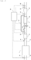
- Fig. 1 shows a schematic arrangement of an intake/exhaust system of the internal combustion engine according to this embodiment.
- the internal combustion engine 1 is the diesel engine for driving the vehicle.
- An intake gas passage 2 and an exhaust gas passage 3 are connected to the internal combustion engine 1.
- An air flow meter 11, which detects the intake air amount of the internal combustion engine 1, is provided for the intake gas passage 2.
- a fuel addition valve 4, a pre-catalyst (front stage catalyst) 5, a urea addition valve 6, a diffusing device 9, SCRF 7, and a post-catalyst (back stage catalyst) 8 are provided for the exhaust gas passage 3 in an order as referred from the upstream side along with the flow of the exhaust gas. Further, a first NOx sensor 12 is provided between the pre-catalyst 5 and the urea addition valve 6 in the exhaust gas passage 3. An exhaust gas temperature sensor 14 is provided between SCRF 7 and the post-catalyst 8 in the exhaust gas passage 3. A second NOx sensor 15 and a PM sensor 16 are provided on the downstream side from the post-catalyst 8 in the exhaust gas passage 3. Further, a pressure difference sensor 13 is provided for the exhaust gas passage 3.
- the pre-catalyst 5 is an oxidation catalyst.
- the pre-catalyst 5 may be any catalyst other than the oxidation catalyst provided that the catalyst has the oxidizing function.
- the fuel addition valve 4 adds the fuel into the exhaust gas in order to supply the fuel to the pre-catalyst 5. Note that the fuel can be also supplied to the pre-catalyst 5 without providing the fuel addition valve 4 such that the subsidiary fuel injection is executed at a timing at which the injected fuel is not subjected to the combustion and the injected fuel is discharged in an unburned state to the exhaust gas passage 3 in the internal combustion engine 1.
- SCRF 7 is constructed such that an SCR catalyst 7a is carried on a wall flow type filter for trapping PM contained in the exhaust gas.
- the SCR catalyst 7a reduces NOx contained in the exhaust gas by using ammonia as the reducing agent.
- the urea addition valve 6 adds an aqueous urea solution into the exhaust gas in order to supply urea as an ammonia precursor to SCRF 7.
- Urea which is added from the urea addition valve 6, is hydrolyzed, and thus ammonia is produced.
- the produced ammonia is once adsorbed to the SCR catalyst 7a carried on SCRF 7. Further, the adsorbed ammonia behaves as the reducing agent, and NOx contained in the exhaust gas is reduced.
- the urea addition valve 6 corresponds to the reducing agent addition valve according to the present invention.
- the reducing agent addition valve according to the present invention may be a device which adds urea as liquid or solid.
- the reducing agent addition valve according to the present invention may be a device which adds ammonia as gas, liquid, or solid.
- the SCR catalyst 7a is a catalyst which reduces NOx by using HC and/or CO as the reducing agent
- the reducing agent addition valve according to the present invention may be a fuel addition valve.
- the diffusing device 9 is a device which is provided in order to diffuse urea contained in the exhaust gas added from the urea addition valve 6.
- Fig. 2 shows a perspective view illustrating a schematic arrangement of the diffusing device 9.
- the diffusing device 9 is provided with a plurality of blades or vanes 9a which are inclined with respect to the flow direction of the exhaust gas.
- the blades 9a protrude from the inner wall surface of the passage toward the central axis, and the blades 9a are installed at equal intervals about the central axis of the passage. According to the arrangement as described above, the exhaust gas, which flows toward the diffusing device 9 from the upstream side in the axial direction of the exhaust gas passage 3, collides with the blades 9a.
- the exhaust gas advances along with the blades 61, and thus the traveling direction of the exhaust gas is changed. Accordingly, the swirling flow of the exhaust gas, which swirls about the center of the central axis of the exhaust gas passage 3, is generated. As a result, urea contained in the exhaust gas is diffused.
- urea When urea is diffused in the exhaust gas flowing into SCRF 7, it is thereby possible to adsorb ammonia in a wider range of the SCR catalyst 7a. Therefore, it is possible to facilitate the reduction of NOx by the SCR catalyst 7a.
- the shape and the number of the blades 9a shown in Fig. 2 are referred to by way of example. It is also allowable to adopt any other shape and any other number thereof.
- the arrangement of the diffusing device according to the present invention is not limited to the arrangement as shown in Fig. 2 . It is also possible to apply any other well-known arrangement.
- the post-catalyst 8 is an oxidation catalyst.
- the post-catalyst 8 may be any other catalyst which has the oxidizing function.
- the post-catalyst 8 may be a catalyst which is constructed by combining an oxidation catalyst and an SCR catalyst for reducing NOx contained in the exhaust gas by using ammonia as the reducing agent.
- the oxidation catalyst may be formed by carrying a noble metal (precious metal) such as platinum (Pt) or the like on a carrier made of a material of aluminum oxide (Al 2 O 3 ), zeolite or the like, and the SCR catalyst may be formed by carrying a base metal (nonprecious metal) such as copper (Cu), iron (Fe) or the like on a carrier made of a material of zeolite.
- a noble metal precious metal
- Au platinum
- Fe iron
- the post-catalyst 8 is the catalyst constructed as described above, it is possible to oxidize HC, CO, and ammonia contained in the exhaust gas. Further, it is possible to produce NOx by oxidizing a part of ammonia, and it is also possible to reduce produced NOx by using excessive ammonia as the reducing agent.
- the first NOx sensor 12 and the second NOx sensor 15 are sensors which detect NOx contained in the exhaust gas.
- the first NOx sensor 12 detects NOx contained in the exhaust gas flowing out from the pre-catalyst 5, i.e., NOx flowing into SCRF 7.
- the second NOx sensor 15 detects NOx contained in the exhaust gas flowing out from the post-catalyst 8, i.e., NOx flowing out from SCRF 7.
- the exhaust gas temperature sensor 14 is a sensor which detects the temperature of the exhaust gas.
- the PM sensor 16 is a sensor which detects PM contained in the exhaust gas.
- the PM sensor 16 detects PM contained in the exhaust gas flowing out from the post-catalyst 8, i.e., PM flowing out from SCRF 7.
- the PM sensor 16 for example, it is possible to use a PM sensor constructed to have a pair of electrodes as the sensor element.
- the electric characteristic which is exemplified, for example, by the resistance value between the pair of electrodes, is changed depending on the PM amount accumulated on the sensor element. Then, the output value of the PM sensor is changed depending on the change of the electric characteristic.
- the pressure difference sensor 13 detects the difference between the exhaust gas pressure which is provided between the pre-catalyst 5 and the urea addition valve 6 in the exhaust gas passage 3 and the exhaust gas pressure which is provided between SCRF 7 and the post-catalyst 8 (the difference in the exhaust gas pressure will be hereinafter referred to as "exhaust gas pressure difference").
- Those connected to the pressure difference sensor 13 are the other end of an upstream side pressure introducing tube having one end connected to the exhaust gas passage 3 between the pre-catalyst 5 and the urea addition valve 6 and the other end of a downstream side pressure introducing tube having one end connected to the exhaust gas passage 3 between SCRF 7 and the post-catalyst 8. Note that the following arrangement or procedure is also available.
- pressure sensors each of which detects the pressure of the exhaust gas, are provided respectively between the pre-catalyst 5 and the urea addition valve 6 in the exhaust gas passage 3 and between SCRF 7 and the post-catalyst 8, in place of the pressure difference sensor 13.
- the exhaust gas pressure difference is calculated on the basis of the output values of the pressure sensors.
- An electronic control unit (ECU) 10 is provided in combination with the internal combustion engine 1.
- Various sensors which include, for example, the air flow meter 11, the first NOx sensor 12, the second NOx sensor 15, the exhaust gas temperature sensor 14, and the PM sensor 16, are electrically connected to ECU 10. Then, output signals of various sensors are inputted into ECU 10. Further, ECU 10 estimates the temperature of the SCRF 7 on the basis of the output value of the exhaust gas temperature sensor 14.
- ECU 10 calculates the PM amount flowing out from SCRF 7 on the basis of the output value of the PM sensor 16. Further, ECU 10 calculates the NOx purification rate of the SCR catalyst 7a carried on SCRF 7 (rate of NOx amount reduced by the SCR catalyst 7a with respect to the NOx amount flowing into SCRF 7), on the basis of the output values of the first NOx sensor 12 and the second NOx sensor 15. Note that the NOx amount flowing into SCRF 7 can be estimated on the basis of, for example, the operation state of the internal combustion engine 1 without providing the first NOx sensor 12, and the NOx purification rate of the SCR catalyst 7a can be calculated by using the estimated value as well.
- ECU 10 executes the fuel addition from the fuel addition valve 4, and thus ECU 10 realizes the filter regeneration process in order to remove PM accumulated on SCRF 7.
- the fuel is supplied to the pre-catalyst 5.
- the heat of combustion heat of oxidation
- the exhaust gas, which flows into SCRF 7 is heated by the heat of combustion. Accordingly, the temperature of SCRF 7 is raised.
- the filter regeneration process is executed, then the fuel addition amount added from the fuel addition valve 4 is controlled, and thus the temperature of SCRF 7 is raised to a predetermined filter regeneration temperature (for example, 600 to 650°C) at which the oxidation of PM is facilitated.
- a predetermined filter regeneration temperature for example, 600 to 650°C
- any breakage which includes, for example, any crack and any dissolution loss, occurs in some cases in SCRF 7 resulting from, for example, any excessive temperature increase caused by the oxidation of PM. Further, in SCRF 7, any clogging-up occurs in some cases on account of any excessive accumulation of PM. If the breakage of SCRF 7 occurs, the pressure difference between the front and the back of SCRF 7 is greatly decreased as compared with that provided in the normal state. On the other hand, if the clogging-up caused by PM occurs in SCRF 7, the pressure difference between the front and the back of SCRF 7 is greatly increased as compared with that provided in the normal state. Therefore, in order to detect the abnormality of SCRF 7 such as the breakage or the clogging-up caused by PM, it is effective to use the pressure difference between the front and the back of SCRF 7.
- the aqueous urea solution is added into the exhaust gas from the urea addition valve 6 on the upstream side from SCRF 7. Therefore, if the upstream side pressure introducing tube, which is provided to introduce the exhaust gas pressure on the upstream side from SCRF 7 into the pressure difference sensor, is connected to the exhaust gas passage 3 on the upstream side from SCRF 7 and on the downstream side from the urea addition valve 6 in order to detect the pressure difference between the front and the back of SCRF 7, it is feared that the deposit or precipitate, which is deposited from the aqueous urea solution, may adhere to the upstream side pressure introducing tube and/or the pressure difference sensor. If the deposit or precipitate as described above adheres to the upstream side pressure introducing tube and/or the pressure difference sensor, it is difficult to correctly detect the pressure difference between the front and the back of SCRF 7.
- the upstream side pressure introducing tube which is provided to introduce the exhaust gas pressure on the upstream side from SCRF 7 into the pressure difference sensor 13, is connected on the upstream side as compared with the urea addition valve 6 in the exhaust gas passage 3. Accordingly, the deposit or precipitate, which is deposited from the aqueous urea solution, can be suppressed from adhering to the upstream side pressure introducing tube and/or the pressure difference sensor 13.
- the exhaust gas pressure difference, which is detected by the pressure difference sensor 13 is the difference between the exhaust gas pressure which is provided on the upstream side from the urea addition valve 6, i.e., on the upstream side from the diffusing device 9 and the exhaust gas pressure which is provided on the downstream side from SCRF 7. Therefore, the exhaust gas pressure difference, which is detected by the pressure difference sensor 13, is changed not only when any abnormality occurs in SCRF 7 but also when any abnormality occurs in the diffusing device 9.
- the exhaust gas pressure difference is greatly decreased as compared with that provided in the normal state when the breakage of the diffusing device 9 occurs in the same manner as when the breakage of SCRF 7 occurs. Further, the exhaust gas pressure difference is greatly increased as compared with that provided in the normal state when the clogging-up of the diffusing device 9 occurs on account of the accumulation of PM on the diffusing device 9 in the same manner as when the clogging-up of SCRF 7 caused by PM occurs. Therefore, it is difficult to distinguish and detect the abnormality of SCRF 7 and the abnormality of the diffusing device 9 on the basis of only the change of the exhaust gas pressure difference detected by the pressure difference sensor 13.
- the abnormality detection is performed on the basis of at least any one of the changes of the NOx purification rate of the SCR catalyst 7a and the PM amount flowing out from SCRF 7 (outflow PM amount) in addition to the change of the exhaust gas pressure difference detected by the pressure difference sensor 13.
- the breakage of SCRF 7, the clogging-up of SCRF 7 caused by PM, and the abnormality of the diffusing device 9 are distinguished and detected.
- the values of the NOx purification rate and the outflow PM amount exhibit the behavior corresponding to the content of the abnormality, in addition to the fact that the exhaust gas pressure difference is greatly changed as compared with that provided in the normal state. Therefore, the respective abnormalities as described above can be distinguished and detected on the basis of the changes of these values.
- FIG. 3 shows a flow chart illustrating the flow of abnormality detection performed for the exhaust gas purification apparatus according to this embodiment. This flow is previously stored in ECU 10, and this flow is repeatedly executed at predetermined intervals.
- Step S101 the value ⁇ Pex/Ga is calculated such that the difference between the exhaust gas pressure difference provided at the present time detected by the pressure difference sensor 13 and the exhaust gas pressure difference provided at a point in time earlier than the present time by a predetermined time, i.e., the amount of change ⁇ Pex of the exhaust gas pressure difference provided during the elapse of the predetermined time is divided by the intake air amount Ga detected by the air flow meter 11.
- the predetermined time is the time in which a certain extent of difference arises between the amount of change of the exhaust gas pressure difference provided when any abnormality occurs in SCRF 7 or the diffusing device 9 and the amount of change of the exhaust gas pressure difference provided in the normal state.
- the predetermined time is previously determined, for example, on the basis of an experiment.
- Step S102 it is judged whether or not the value ⁇ Pex/Ga, which is calculated in Step S101, is larger than a predetermined threshold value ⁇ Pex/Ga0.
- the threshold value ⁇ Pex/Ga0 is the upper limit value of a range in which it is possible to judge that any abnormality does not occur in any one of SCRF 7 and the diffusing device 9, i.e., a proper range.
- the threshold value ⁇ Pex/Ga0 is the value which is decided depending on, for example, the estimated value of the PM accumulation amount of SCRF 7 provided if it is assumed that the operation state of the internal combustion engine 1 and SCRF 7 are normal.
- the threshold value ⁇ Pex/Ga0 can be determined, for example, on the basis of an experiment. Note that the threshold value ⁇ Pex/Ga0 may be a predetermined fixed value.
- Step S102 If the affirmative judgment is made in Step S102, the process of Step S103 is subsequently executed. On the other hand, if the negative judgment is made in Step S102, i.e., if ⁇ Pex/Ga is not more than the predetermined threshold value ⁇ Pex/Ga0, then it is possible to judge that any abnormality does not occur in any one of SCRF 7 and the diffusing device 9. In this case, the execution of this flow is once completed.
- the amount of change ⁇ Pex itself of the exhaust gas pressure difference may be used as a parameter for the abnormality detection in place of the value ⁇ Pex/Ga obtained by dividing the amount of change ⁇ Pex of the exhaust gas pressure difference by the intake air amount Ga.
- the value of the exhaust gas pressure difference changes depending on the flow rate of the exhaust gas discharged from the internal combustion engine 1. Further, the flow rate of the exhaust gas discharged from the internal combustion engine 1 is correlated with the intake air amount Ga. Therefore, it is possible to raise the accuracy of the abnormality detection by using, as the parameter for the abnormality detection, the value ⁇ Pex/Ga obtained by dividing the amount of change ⁇ Pex of the exhaust gas pressure difference by the intake air amount Ga.
- Step S103 the amount of increase ⁇ Qpm of the outflow PM amount provided at the present time calculated on the basis of the output value of the PM sensor 16 with respect to the outflow PM amount provided at the point in time earlier than the present time by the predetermined time is calculated.
- the amount of increase ⁇ Qpm of the outflow PM amount is the amount of increase of the outflow PM amount provided during the period in which the predetermined time elapses.
- Step S104 it is judged whether or not the amount of increase ⁇ Qpm of the outflow PM amount calculated in Step S103 is not more than a predetermined threshold value ⁇ Qpm0. If SCRF 7 is broken, PM flows out from the broken portion without being trapped. Therefore, the outflow PM amount is greatly increased as compared with that provided in the normal state. On the other hand, even when the clogging-up of SCRF 7 caused by PM or the abnormality of the diffusing device 9 occurs, the outflow PM amount is not greatly increased as compared with that provided in the normal state.
- the predetermined threshold value ⁇ Qpm0 is the upper limit value of a range in which it is possible to judge that SCRF 7 is not broken, i.e., a proper range.
- the threshold value ⁇ Qpm0 is the value which is decided depending on, for example, the operation state of the internal combustion engine 1 and/or the estimated value of the PM accumulation amount of SCRF 7 provided if it is assumed that SCRF 7 is normal.
- the threshold value ⁇ Qpm0 can be determined, for example, on the basis of an experiment. Note that the threshold value ⁇ Qpm0 may be a predetermined fixed value.
- Step S104 If the negative judgment is made in Step S104, i.e., if the amount of increase ⁇ Qpm of the outflow PM amount is larger than the predetermined threshold value ⁇ Qpm0, then the process of Step S108 is subsequently executed. In Step S108, it is judged that the breakage of SCRF 7 occurs.
- Step S105 the amount of decrease ⁇ Rnox of the NOx purification rate provided at the present time calculated on the basis of the output values of the first NOx sensor 12 and the second NOx sensor 15 with respect to the NOx purification rate provided at the point in time earlier than the present time by the predetermined time is calculated.
- the amount of decrease ⁇ Rnox of the NOx purification rate is the amount of decrease of the NOx purification rate provided during the period in which the predetermined time elapses.
- Step S106 it is judged whether or not the amount of decrease ⁇ Rnox of the NOx purification rate calculated in Step S105 is larger than a predetermined threshold value ⁇ Rnox0. If the abnormality of the diffusing device 9 occurs, urea is hardly diffused in the exhaust gas. As a result, the NOx purification rate is greatly lowered as compared with that provided in the normal state. On the other hand, even when the clogging-up of SCRF 7 caused by PM occurs, the NOx purification rate is not greatly lowered as compared with that provided in the normal state.
- the predetermined threshold value ⁇ Rnox0 is the upper limit value of a range in which it is possible to judge that the diffusing device 9 is normal, i.e., a proper range.
- the threshold value ⁇ Rnox0 is the value which is decided depending on, for example, the operation state of the internal combustion engine 1.
- the threshold value ⁇ Rnox0 can be determined, for example, on the basis of an experiment. Note that the threshold value ⁇ Rnox0 may be a predetermined fixed value.
- Step S106 If the affirmative judgment is made in Step S106, the process of Step S107 is subsequently executed. In Step S107, it is judged that the abnormality of the diffusing device 9 occurs. On the other hand, if the negative judgment is made in Step S106, i.e., if the amount of decrease ⁇ Rnox of the NOx purification rate is not more than the predetermined threshold value ⁇ Rnox0, then the process of Step S109 is subsequently executed. In Step S109, it is judged that the clogging-up of SCRF 7 caused by PM occurs.
- Fig. 4 shows a flow chart illustrating a flow of abnormality detection performed for the exhaust gas purification apparatus according to a modified embodiment of the embodiment of the present invention. This flow is previously stored in ECU 10, and this flow is repeatedly executed at predetermined intervals.
- Step S102 the processes of Steps S105 and S106 are executed firstly.
- Step S105 if the amount of decrease ⁇ Rnox of the NOx purification rate calculated in Step S105 is not more than the predetermined threshold value ⁇ Rnox0, it is possible to judge that the clogging-up of SCRF 7 caused by PM occurs. Therefore, if the negative judgment is made in Step S106, the process of Step S109 is subsequently executed in the same manner as in the flow shown in Fig. 3 .
- Step S106 if the affirmative judgment is made in Step S106, the processes of Steps S103 and S104 are executed. Also in this case, if the amount of increase ⁇ Qpm of the outflow PM amount calculated in Step S103 is larger than the predetermined threshold value ⁇ Qpm0, it is possible to judge that the breakage of SCRF 7 occurs. Further, if the amount of increase ⁇ Qpm of the outflow PM amount calculated in Step S103 is not more than the predetermined threshold value ⁇ Qpm0, it is possible to judge that the abnormality of the diffusing device 9 occurs. Therefore, if the affirmative judgment is made in Step S106, the process of Step S107 is subsequently executed. If the negative judgment is made, the process of Step S108 is subsequently executed.
- ⁇ Pex, ⁇ Qpm, and ⁇ Rnox are differences between the values provided at the present time and the values provided in the normal state in relation to the exhaust gas pressure difference, the outflow PM amount, and the NOx purification rate respectively.
- ⁇ Pex may be a difference between the exhaust gas pressure difference provided at the present time detected by the pressure difference sensor 13 and the estimated value of the exhaust gas pressure difference provided if it is assumed that the SCRF 7 and the diffusing device 9 are normal.
- ⁇ Qpm may be an amount of increase of the outflow PM amount provided at the present time calculated on the basis of the output value of the PM sensor 16 with respect to the estimated value of the outflow PM amount provided if it is assumed that SCRF 7 is normal.
- ⁇ Rnox may be an amount of decrease of the NOx purification rate provided at the present time calculated on the basis of the output values of the first NOx sensor 12 and the second NOx sensor 15 with respect to the estimated value of the NOx purification rate provided if it is assumed that SCRF 7 and the diffusing device 9 are normal.
- the exhaust gas pressure difference provided if it is assumed that SCRF 7 and the diffusing device 9 are normal, the outflow PM amount provided if it is assumed that SCRF 7 is normal, and the NOx purification rate provided if it is assumed that SCRF 7 and the diffusing device 9 are normal can be estimated on the basis of, for example, the operation state of the internal combustion engine 1 and the estimated value of the PM accumulation amount of SCRF 7 provided if it is assumed that SCRF 7 is normal.
- the estimated values of these values may be previously determined, for example, on the basis of an experiment, and they may be stored beforehand as a map or a function in ECU 10.
- ⁇ Rnox is larger than the threshold value and ⁇ Qpm is smaller than the threshold value when the value ⁇ Pex/Ga obtained by dividing the difference ⁇ Pex of the exhaust gas pressure difference by the intake air amount Ga exceeds the threshold value, then it is possible to judge that the abnormality of the diffusing device 9 occurs.
Landscapes
- Engineering & Computer Science (AREA)
- Chemical & Material Sciences (AREA)
- Combustion & Propulsion (AREA)
- Mechanical Engineering (AREA)
- General Engineering & Computer Science (AREA)
- Chemical Kinetics & Catalysis (AREA)
- Health & Medical Sciences (AREA)
- Toxicology (AREA)
- Materials Engineering (AREA)
- Exhaust Gas After Treatment (AREA)
- Processes For Solid Components From Exhaust (AREA)
- Filtering Of Dispersed Particles In Gases (AREA)
- Exhaust Gas Treatment By Means Of Catalyst (AREA)
Claims (6)
- Dispositif de détection d'anomalie pour un appareil de purification de gaz d'échappement, pour détecter une anomalie de l'appareil de purification de gaz d'échappement, comprenant :un filtre (7) qui est prévu pour un passage de gaz d'échappement d'un moteur à combustion interne et qui piège la matière particulaire contenue dans un gaz d'échappement, le filtre (7) comprenant un catalyseur de NOx à réduction catalytique sélective (7a) supporté sur celui-ci ;une vanne d'ajout de réducteur (6) qui est prévue pour le passage de gaz d'échappement (3) d'un côté amont du filtre (7) et qui ajoute un réducteur dans le gaz d'échappement ; etun dispositif de diffusion (9) qui est prévu pour le passage de gaz d'échappement (3) entre le filtre (7) et la vanne d'ajout de réducteur (6) et qui diffuse le réducteur contenu dans le gaz d'échappement, le dispositif de détection d'anomalie pour l'appareil de purification de gaz d'échappement comprenant :une unité de jugement (S107, S108, S109) configurée pour juger laquelle des anomalies consistant en un encrassement quelconque du filtre (7) provoqué par la matière particulaire et en une anomalie quelconque du dispositif de diffusion (9) se produit, sur la base d'une différence entre un taux de purification de NOx du catalyseur de NOx à réduction catalytique sélective (7a) supporté sur le filtre (7) et un taux de purification de NOx prédéterminé, lorsqu'une différence, qui est fournie entre une différence de pression de gaz d'échappement en tant que différence entre une pression de gaz d'échappement d'un côté amont de la vanne d'ajout de réducteur (9) et une pression de gaz d'échappement d'un côté aval du filtre (7) et une différence de pression de gaz d'échappement prédéterminée, dépasse une certaine quantité, et qu'une différence, qui est fournie entre une quantité de matière particulaire s'écoulant hors du filtre (7) et une quantité de matière particulaire d'écoulement de sortie prédéterminée, est inférieure ou égale à une valeur de seuil prédéterminée.
- Dispositif de détection d'anomalie pour l'appareil de purification de gaz d'échappement selon la revendication 1, dans lequel :la différence de pression de gaz d'échappement prédéterminée est une différence de pression de gaz d'échappement fournie à un instant précédant un instant actuel d'un temps prédéterminé ;le taux de purification de NOx prédéterminé est un taux de purification de NOx du catalyseur de NOx à réduction catalytique sélective (7a) supporté sur le filtre (7) fourni à l'instant précédant l'instant actuel du temps prédéterminé ; etla quantité de matière particulaire d'écoulement de sortie prédéterminée est une quantité de matière particulaire s'écoulant hors du filtre (7) fournie à un instant précédant l'instant actuel du temps prédéterminé.
- Dispositif de détection d'anomalie pour l'appareil de purification de gaz d'échappement selon la revendication 1, dans lequel :la différence de pression de gaz d'échappement prédéterminée est une valeur estimée de la différence de pression de gaz d'échappement fournie s'il est supposé que le filtre (7) et le dispositif de diffusion (9) sont normaux ;le taux de purification de NOx prédéterminé est une valeur estimée du taux de purification de NOx du catalyseur de NOx à réduction catalytique sélective (7a) supporté sur le filtre (7) fourni s'il est supposé que le filtre (7) et le dispositif de diffusion (9) sont normaux ; etla quantité de matière particulaire d'écoulement de sortie prédéterminée est une valeur estimée de la quantité de matière particulaire s'écoulant hors du filtre (7) fournie s'il est supposé que le filtre (7) est normal.
- Dispositif de détection d'anomalie pour l'appareil de purification de gaz d'échappement selon l'une quelconque des revendications 1 à 3, dans lequel l'unité de jugement est configurée pour juger que l'encrassement du filtre (7) provoqué par la matière particulaire se produit si une quantité de diminution du taux de purification de NOx du catalyseur de NOx à réduction catalytique sélective (7a) supporté sur le filtre (7) par rapport au taux de purification de NOx prédéterminé est inférieure ou égale à une valeur de seuil, lorsque la différence entre la différence de pression de gaz d'échappement et la différence de pression de gaz d'échappement prédéterminée dépasse la certaine quantité, et que la différence, qui est fournie entre la quantité de matière particulaire s'écoulant hors du filtre (7) et la quantité de matière particulaire d'écoulement de sortie prédéterminée, est inférieure ou égale à la valeur de seuil prédéterminée.
- Dispositif de détection d'anomalie pour l'appareil de purification de gaz d'échappement selon l'une quelconque des revendications 1 à 3, dans lequel l'unité de jugement est configurée pour juger que l'anomalie du dispositif de diffusion se produit si une quantité de diminution du taux de purification de NOx du catalyseur de NOx à réduction catalytique sélective (7a) supporté sur le filtre (7) par rapport au taux de purification de NOx prédéterminé est supérieure à une valeur de seuil, lorsque la différence entre la différence de pression de gaz d'échappement et la différence de pression de gaz d'échappement prédéterminée dépasse la certaine quantité, et que la différence, qui est fournie entre la quantité de matière particulaire s'écoulant hors du filtre et la quantité de matière particulaire d'écoulement de sortie prédéterminée, est inférieure ou égale à la valeur de seuil prédéterminée.
- Dispositif de détection d'anomalie pour l'appareil de purification de gaz d'échappement selon la revendication 4, dans lequel l'unité de jugement est configurée pour juger que l'anomalie du dispositif de diffusion se produit si une quantité de diminution du taux de purification de NOx du catalyseur de NOx à réduction catalytique sélective supporté sur le filtre par rapport au taux de purification de NOx prédéterminé est supérieure à la valeur de seuil, lorsque la différence entre la différence de pression de gaz d'échappement et la différence de pression de gaz d'échappement prédéterminée dépasse la certaine quantité, et que la différence, qui est fournie entre la quantité de matière particulaire s'écoulant hors du filtre (7) et la quantité de matière particulaire d'écoulement de sortie prédéterminée, est inférieure ou égale à la valeur de seuil prédéterminée.
Applications Claiming Priority (1)
| Application Number | Priority Date | Filing Date | Title |
|---|---|---|---|
| PCT/JP2012/081776 WO2014087536A1 (fr) | 2012-12-07 | 2012-12-07 | Dispositif permettant de détecter une anomalie dans un purificateur de gaz d'échappement |
Publications (3)
| Publication Number | Publication Date |
|---|---|
| EP2930323A1 EP2930323A1 (fr) | 2015-10-14 |
| EP2930323A4 EP2930323A4 (fr) | 2016-02-17 |
| EP2930323B1 true EP2930323B1 (fr) | 2017-03-29 |
Family
ID=50882980
Family Applications (1)
| Application Number | Title | Priority Date | Filing Date |
|---|---|---|---|
| EP12889509.1A Not-in-force EP2930323B1 (fr) | 2012-12-07 | 2012-12-07 | Dispositif permettant de détecter une anomalie pour un purificateur de gaz d'échappement |
Country Status (5)
| Country | Link |
|---|---|
| US (1) | US9879586B2 (fr) |
| EP (1) | EP2930323B1 (fr) |
| JP (1) | JP5907284B2 (fr) |
| CN (1) | CN104838101B (fr) |
| WO (1) | WO2014087536A1 (fr) |
Cited By (1)
| Publication number | Priority date | Publication date | Assignee | Title |
|---|---|---|---|---|
| CN110657011A (zh) * | 2019-09-30 | 2020-01-07 | 潍柴动力股份有限公司 | Scr堵塞故障检测方法、scr堵塞故障检测装置及车辆 |
Families Citing this family (26)
| Publication number | Priority date | Publication date | Assignee | Title |
|---|---|---|---|---|
| CN104884754B (zh) * | 2012-12-13 | 2017-11-14 | 丰田自动车株式会社 | 排气净化装置的故障诊断装置 |
| US9574714B2 (en) * | 2013-07-29 | 2017-02-21 | Nordson Corporation | Adhesive melter and method having predictive maintenance for exhaust air filter |
| CN105829670B (zh) * | 2013-12-19 | 2018-07-24 | 丰田自动车株式会社 | 内燃机的排气净化系统 |
| JP6280462B2 (ja) * | 2014-06-30 | 2018-02-14 | ヤンマー株式会社 | 排気浄化装置 |
| CN104314652A (zh) * | 2014-08-15 | 2015-01-28 | 潍柴动力股份有限公司 | 一种scr箱损坏的检测方法和检测装置 |
| DE102014016347A1 (de) * | 2014-11-05 | 2016-05-12 | Daimler Ag | Verfahren zum Ermitteln einer Rußbeladung eines mit einer selektiv katalytischen Beschichtung versehenen Partikelfilters |
| JP6090293B2 (ja) * | 2014-12-08 | 2017-03-08 | トヨタ自動車株式会社 | フィルタの機能診断装置 |
| JP6032268B2 (ja) * | 2014-12-22 | 2016-11-24 | トヨタ自動車株式会社 | フィルタの故障診断装置 |
| SE541017C2 (en) * | 2015-02-17 | 2019-03-05 | Scania Cv Ab | A method and a system for determining a flow resistance across a particulate filter |
| JP6387884B2 (ja) * | 2015-04-06 | 2018-09-12 | 株式会社デンソー | 排出ガス浄化装置 |
| CN107923291B (zh) * | 2015-08-28 | 2021-05-11 | 斗山英维高株式会社 | 废气净化系统及其监测方法 |
| JP6288054B2 (ja) | 2015-11-27 | 2018-03-07 | トヨタ自動車株式会社 | 排気浄化システムの故障診断装置 |
| GB2530203A (en) * | 2015-12-10 | 2016-03-16 | Gm Global Tech Operations Inc | A method of detecting a catalyst of a selective catalytic reduction system |
| JP6319284B2 (ja) * | 2015-12-17 | 2018-05-09 | トヨタ自動車株式会社 | 内燃機関の排気浄化システム |
| JP6436075B2 (ja) * | 2015-12-25 | 2018-12-12 | トヨタ自動車株式会社 | 排気浄化システムの故障診断装置 |
| DE102016201602A1 (de) * | 2016-02-03 | 2017-08-03 | Robert Bosch Gmbh | Verfahren zur Ermittlung eines Ammoniakmassenstroms |
| US10876454B2 (en) * | 2018-11-08 | 2020-12-29 | Faurecia Emissions Control Technologies, Usa, Llc | Automotive exhaust aftertreatment system with multi-reductant injection and doser controls |
| JP7088079B2 (ja) * | 2019-02-28 | 2022-06-21 | トヨタ自動車株式会社 | 内燃機関の制御装置 |
| EP3786614A1 (fr) * | 2019-08-29 | 2021-03-03 | Carl Freudenberg KG | Procédé de fourniture d'un flux d'air |
| US11193413B2 (en) | 2019-12-12 | 2021-12-07 | Faurecia Emissions Control Technologies, Usa, Llc | Exhaust aftertreatment system with virtual temperature determination and control |
| US11319853B2 (en) | 2020-03-31 | 2022-05-03 | Faurecia Emissions Control Technologies, Usa, Llc | Automotive exhaust aftertreatment system with doser |
| US11022014B1 (en) | 2020-04-28 | 2021-06-01 | Faurecia Emissions Control Technologies, Usa, Llc | Exhaust aftertreatment system with heated flash-boiling doser |
| US11511239B2 (en) | 2020-04-29 | 2022-11-29 | Faurecia Emissions Control Technologies, Usa, Llc | Heated flash-boiling doser with integrated helix |
| US11092054B1 (en) | 2020-04-29 | 2021-08-17 | Faurecia Emissions Control Technologies, Usa, Llc | Flash-boiling doser with thermal transfer helix |
| US11384667B2 (en) | 2020-05-29 | 2022-07-12 | Faurecia Emissions Control Technologies, Usa, Llc | Exhaust aftertreatment system with heated dosing control |
| US11225894B1 (en) | 2020-06-30 | 2022-01-18 | Faurecia Emissions Control Technologies, Usa, Llc | Exhaust aftertreatment system with thermally controlled reagent doser |
Family Cites Families (68)
| Publication number | Priority date | Publication date | Assignee | Title |
|---|---|---|---|---|
| DE10110340A1 (de) * | 2001-03-03 | 2002-09-12 | Bosch Gmbh Robert | Verfahren und Vorrichtung zur Steuerung einer Brennkraftmaschine |
| WO2004042222A1 (fr) * | 2002-11-08 | 2004-05-21 | Emitec Gesellschaft Für Emissionstechnologie Mbh | Systeme d'echappement de gaz et procede pour le faire fonctionner |
| JP4090972B2 (ja) * | 2003-09-19 | 2008-05-28 | 日産ディーゼル工業株式会社 | エンジンの排気浄化装置 |
| JP3718209B2 (ja) * | 2003-10-03 | 2005-11-24 | 日産ディーゼル工業株式会社 | エンジンの排気浄化装置 |
| JP4326976B2 (ja) * | 2003-10-22 | 2009-09-09 | 日産ディーゼル工業株式会社 | エンジンの排気浄化装置 |
| FR2862708B1 (fr) * | 2003-11-24 | 2008-01-18 | Inst Francais Du Petrole | Procede et dispositif de desulfatation d'un piege a oxydes nitriques et de regeneration d'un filtre a particules |
| JP4161931B2 (ja) * | 2004-04-07 | 2008-10-08 | いすゞ自動車株式会社 | 排気ガス浄化システムの制御方法及び排気ガス浄化システム |
| JP4161932B2 (ja) * | 2004-04-09 | 2008-10-08 | いすゞ自動車株式会社 | 排気ガス浄化システムの制御方法及び排気ガス浄化システム |
| US7213395B2 (en) * | 2004-07-14 | 2007-05-08 | Eaton Corporation | Hybrid catalyst system for exhaust emissions reduction |
| JP2006125247A (ja) * | 2004-10-27 | 2006-05-18 | Hitachi Ltd | エンジンの排気ガス浄化方法及び排気ガス浄化装置 |
| EP1857647A4 (fr) * | 2005-01-31 | 2015-03-25 | Isuzu Motors Ltd | Procédé pour relever la température de l'épurateur de gaz d'échappement et système d'épuration de gaz d'échappement |
| KR100909820B1 (ko) * | 2005-02-28 | 2009-07-28 | 얀마 가부시키가이샤 | 배기가스 정화장치 및 그 배기가스 정화장치를 구비한내연기관 및 미립자 필터 재생 방법 |
| JP3938188B2 (ja) * | 2005-05-17 | 2007-06-27 | いすゞ自動車株式会社 | 排気ガス浄化システムの制御方法及び排気ガス浄化システム |
| JP4665633B2 (ja) * | 2005-07-12 | 2011-04-06 | 株式会社デンソー | 内燃機関の排気浄化装置 |
| JP3988776B2 (ja) * | 2005-07-15 | 2007-10-10 | いすゞ自動車株式会社 | 排気ガス浄化システムの制御方法及び排気ガス浄化システム |
| JP4710564B2 (ja) * | 2005-11-22 | 2011-06-29 | いすゞ自動車株式会社 | 排気ガス浄化システムの制御方法及び排気ガス浄化システム |
| EP1961929A1 (fr) * | 2005-12-05 | 2008-08-27 | Ngk Insulators, Ltd. | Corps à structure en nid d abeilles et son procédé de production |
| DE102005061873A1 (de) | 2005-12-23 | 2007-07-05 | Robert Bosch Gmbh | Verfahren und Steuergerät zum Betreiben eines integrierten SCR/DPF-Systems |
| JP4673226B2 (ja) * | 2006-01-27 | 2011-04-20 | いすゞ自動車株式会社 | 排気ガス浄化方法及び排気ガス浄化システム |
| US20070178025A1 (en) * | 2006-01-31 | 2007-08-02 | Opris Cornelius N | Exhaust treatment system |
| JP3988785B2 (ja) * | 2006-02-01 | 2007-10-10 | いすゞ自動車株式会社 | 排気ガス浄化システムの制御方法及び排気ガス浄化システム |
| JP4956784B2 (ja) * | 2006-03-07 | 2012-06-20 | 日産自動車株式会社 | 排ガス浄化フィルタのパティキュレート堆積量検出装置及び検出方法 |
| JP4415963B2 (ja) * | 2006-03-17 | 2010-02-17 | トヨタ自動車株式会社 | 内燃機関の排気浄化装置 |
| JP4762043B2 (ja) | 2006-04-27 | 2011-08-31 | 本田技研工業株式会社 | パティキュレートフィルタの状態検知装置 |
| JP2007315275A (ja) * | 2006-05-25 | 2007-12-06 | Nissan Motor Co Ltd | 排気浄化フィルタ故障診断装置及び方法 |
| JP4513785B2 (ja) * | 2006-06-21 | 2010-07-28 | トヨタ自動車株式会社 | 内燃機関の排気浄化装置 |
| JP4404073B2 (ja) * | 2006-06-30 | 2010-01-27 | トヨタ自動車株式会社 | 内燃機関の排気浄化装置 |
| JP4100440B2 (ja) * | 2006-09-26 | 2008-06-11 | トヨタ自動車株式会社 | ハイブリッド車両の制御装置 |
| US20080155972A1 (en) * | 2006-12-28 | 2008-07-03 | James Joshua Driscoll | Exhaust treatment system |
| US20080202101A1 (en) * | 2007-02-23 | 2008-08-28 | Driscoll James J | Exhaust treatment system |
| JP5119690B2 (ja) * | 2007-03-12 | 2013-01-16 | トヨタ自動車株式会社 | 内燃機関の排気ガス浄化装置 |
| JP4349425B2 (ja) * | 2007-03-19 | 2009-10-21 | 日産自動車株式会社 | NOx触媒の診断装置 |
| JP4877123B2 (ja) * | 2007-07-23 | 2012-02-15 | マツダ株式会社 | エンジンの排気浄化装置 |
| JP2009275631A (ja) * | 2008-05-15 | 2009-11-26 | Toyota Motor Corp | 車両の制御装置および制御方法 |
| JP2009293518A (ja) * | 2008-06-05 | 2009-12-17 | Denso Corp | 内燃機関の排気浄化装置 |
| US20100139258A1 (en) * | 2008-12-04 | 2010-06-10 | Caterpillar Inc. | Exhaust mixer with backward flow |
| EP2402569A4 (fr) * | 2009-02-24 | 2016-01-06 | Toyota Motor Co Ltd | Système de diagnostic d'anomalies et procédé de diagnostic d'anomalies dans un système de régénération de filtre |
| JP2011033001A (ja) * | 2009-08-05 | 2011-02-17 | Toyota Industries Corp | 排気ガス浄化装置 |
| US20110030343A1 (en) * | 2009-08-06 | 2011-02-10 | Caterpillar Inc. | Scr reductant deposit removal |
| JP2011528088A (ja) * | 2009-09-18 | 2011-11-10 | クワン ソン カンパニー リミテッド | バイパスシステムを有するscrシステム |
| JP2011099333A (ja) * | 2009-11-04 | 2011-05-19 | Hino Motors Ltd | 排気浄化装置 |
| US8683790B2 (en) * | 2009-11-10 | 2014-04-01 | GM Global Technology Operations LLC | Nozzle diffuser mixer |
| CN102741517B (zh) * | 2009-12-23 | 2016-03-09 | 卡特彼勒公司 | 废气后处理系统 |
| US8631647B2 (en) * | 2010-01-21 | 2014-01-21 | Westport Power Inc. | System and method for regenerating an engine exhaust after-treatment device |
| JP5088391B2 (ja) * | 2010-03-09 | 2012-12-05 | トヨタ自動車株式会社 | パティキュレートフィルタの故障判別装置 |
| CN102782274B (zh) * | 2010-03-18 | 2015-05-13 | 丰田自动车株式会社 | 内燃机的排气净化装置 |
| JP5644164B2 (ja) * | 2010-04-15 | 2014-12-24 | いすゞ自動車株式会社 | 排気ガス浄化装置 |
| EP2568134B1 (fr) * | 2010-05-07 | 2019-07-24 | Yanmar Co., Ltd. | Système d'épuration des gaz d'échappement |
| JP5625475B2 (ja) * | 2010-05-17 | 2014-11-19 | いすゞ自動車株式会社 | 排ガス浄化システム |
| JP5839784B2 (ja) * | 2010-06-02 | 2016-01-06 | ヤンマー株式会社 | 排気ガス浄化システム |
| US20120023911A1 (en) * | 2010-07-28 | 2012-02-02 | Gm Global Technology Operations, Inc. | Detection of exhaust particulate filter substrate failure |
| JP5548882B2 (ja) * | 2010-08-27 | 2014-07-16 | 日立建機株式会社 | 作業車両の排気ガス浄化システム |
| US20110165040A1 (en) * | 2010-11-03 | 2011-07-07 | Ford Global Technologies, Llc | Device for remediating emissions and method of manufacture |
| JP5368414B2 (ja) * | 2010-11-05 | 2013-12-18 | 日立建機株式会社 | 排気ガス浄化装置を備えた建設機械用油圧駆動システム |
| JP5658075B2 (ja) * | 2011-04-15 | 2015-01-21 | 日立建機株式会社 | 作業機の排気浄化システム |
| JP5941054B2 (ja) * | 2011-10-04 | 2016-06-29 | 日立建機株式会社 | 排気ガス浄化装置を備えた建設機械用油圧駆動システム |
| JP5998503B2 (ja) * | 2012-02-07 | 2016-09-28 | マツダ株式会社 | 多気筒エンジンの吸排気装置 |
| JP6074912B2 (ja) * | 2012-05-11 | 2017-02-08 | いすゞ自動車株式会社 | 排気ガス浄化システム及び排気ガス浄化方法 |
| JP2013241859A (ja) * | 2012-05-18 | 2013-12-05 | Isuzu Motors Ltd | 排気ガス浄化システム及び排気ガス浄化方法 |
| US20140260511A1 (en) * | 2013-03-13 | 2014-09-18 | Rosemount Analytical Inc. | Diffuser diagnostic for in-situ flue gas measurement device |
| US9238991B2 (en) * | 2013-04-29 | 2016-01-19 | GM Global Technology Operations LLC | Internal combustion engine and exhaust aftertreatment system |
| US20140352280A1 (en) * | 2013-06-02 | 2014-12-04 | Baohua Qi | Air driven reductant dosing system |
| US9371764B2 (en) * | 2013-08-01 | 2016-06-21 | GM Global Technology Operations LLC | After-treatment component |
| CN106464311B (zh) * | 2014-06-06 | 2020-11-27 | 滤波器感知技术有限公司 | 射频过程感测、控制和诊断系统 |
| US9624805B2 (en) * | 2014-08-26 | 2017-04-18 | Caterpillar Inc. | Aftertreatment system having dynamic independent injector control |
| US9677447B2 (en) * | 2014-12-05 | 2017-06-13 | Caterpillar Inc. | Aftertreatment module having replaceable catalyst housing |
| US9605579B2 (en) * | 2014-12-12 | 2017-03-28 | General Electric Company | Systems and methods for model based control of catalytic converter systems |
| US20160194995A1 (en) * | 2016-03-11 | 2016-07-07 | Caterpillar Inc. | Flow mixing device for an exhaust after-treatment system |
-
2012
- 2012-12-07 EP EP12889509.1A patent/EP2930323B1/fr not_active Not-in-force
- 2012-12-07 US US14/649,713 patent/US9879586B2/en not_active Expired - Fee Related
- 2012-12-07 CN CN201280077555.5A patent/CN104838101B/zh not_active Expired - Fee Related
- 2012-12-07 WO PCT/JP2012/081776 patent/WO2014087536A1/fr not_active Ceased
- 2012-12-07 JP JP2014550873A patent/JP5907284B2/ja active Active
Cited By (2)
| Publication number | Priority date | Publication date | Assignee | Title |
|---|---|---|---|---|
| CN110657011A (zh) * | 2019-09-30 | 2020-01-07 | 潍柴动力股份有限公司 | Scr堵塞故障检测方法、scr堵塞故障检测装置及车辆 |
| CN110657011B (zh) * | 2019-09-30 | 2021-10-08 | 潍柴动力股份有限公司 | Scr堵塞故障检测方法、scr堵塞故障检测装置及车辆 |
Also Published As
| Publication number | Publication date |
|---|---|
| WO2014087536A1 (fr) | 2014-06-12 |
| US9879586B2 (en) | 2018-01-30 |
| CN104838101A (zh) | 2015-08-12 |
| JPWO2014087536A1 (ja) | 2017-01-05 |
| US20150315950A1 (en) | 2015-11-05 |
| JP5907284B2 (ja) | 2016-04-26 |
| EP2930323A4 (fr) | 2016-02-17 |
| CN104838101B (zh) | 2018-01-02 |
| EP2930323A1 (fr) | 2015-10-14 |
Similar Documents
| Publication | Publication Date | Title |
|---|---|---|
| EP2930323B1 (fr) | Dispositif permettant de détecter une anomalie pour un purificateur de gaz d'échappement | |
| US9476341B2 (en) | Exhaust treatment system that generates debounce duration for NOx sensor offset | |
| KR101440009B1 (ko) | 내연 기관의 배기 정화 장치 | |
| CN104364484B (zh) | 异常诊断装置以及内燃机的排气净化装置 | |
| JP5170689B2 (ja) | 内燃機関の排気浄化装置 | |
| EP2921665B1 (fr) | Système de purification de gaz d'échappement pour moteur à combustion interne | |
| JP2009121413A (ja) | 排気浄化システムの異常診断装置 | |
| EP2921667B1 (fr) | Dispositif de purification de gaz d'échappement pour un moteur à combustion interne | |
| WO2010079621A1 (fr) | Appareil de détermination d’un élément traversant un catalyseur, et appareil de purification de gaz d'échappement pour moteur à combustion interne | |
| CN104884756B (zh) | 内燃机的排气净化装置 | |
| JPWO2014102932A1 (ja) | 内燃機関の排気浄化システム | |
| EP2927445B1 (fr) | Système de purification de gaz d'échappement pour moteur à combustion interne | |
| AU2011377329B2 (en) | Exhaust purification device for internal combustion engine | |
| EP3342998B1 (fr) | Appareil de purification de gaz d'échappement pour moteur à combustion interne | |
| US20130086886A1 (en) | Electrically heated oxidation catalyst particulate matter protection | |
| JP2013181465A (ja) | 排気浄化装置の異常検出システム |
Legal Events
| Date | Code | Title | Description |
|---|---|---|---|
| PUAI | Public reference made under article 153(3) epc to a published international application that has entered the european phase |
Free format text: ORIGINAL CODE: 0009012 |
|
| 17P | Request for examination filed |
Effective date: 20150611 |
|
| AK | Designated contracting states |
Kind code of ref document: A1 Designated state(s): AL AT BE BG CH CY CZ DE DK EE ES FI FR GB GR HR HU IE IS IT LI LT LU LV MC MK MT NL NO PL PT RO RS SE SI SK SM TR |
|
| AX | Request for extension of the european patent |
Extension state: BA ME |
|
| RA4 | Supplementary search report drawn up and despatched (corrected) |
Effective date: 20160118 |
|
| RIC1 | Information provided on ipc code assigned before grant |
Ipc: F01N 3/20 20060101ALI20160112BHEP Ipc: F01N 3/023 20060101AFI20160112BHEP Ipc: F01N 11/00 20060101ALI20160112BHEP Ipc: F01N 9/00 20060101ALI20160112BHEP Ipc: F01N 3/24 20060101ALI20160112BHEP Ipc: F01N 3/035 20060101ALI20160112BHEP Ipc: F01N 3/08 20060101ALI20160112BHEP Ipc: F01N 3/28 20060101ALI20160112BHEP Ipc: F01N 3/025 20060101ALI20160112BHEP Ipc: F01N 3/10 20060101ALI20160112BHEP Ipc: F01N 3/021 20060101ALI20160112BHEP Ipc: F01N 13/00 20100101ALI20160112BHEP |
|
| DAX | Request for extension of the european patent (deleted) | ||
| GRAP | Despatch of communication of intention to grant a patent |
Free format text: ORIGINAL CODE: EPIDOSNIGR1 |
|
| GRAJ | Information related to disapproval of communication of intention to grant by the applicant or resumption of examination proceedings by the epo deleted |
Free format text: ORIGINAL CODE: EPIDOSDIGR1 |
|
| INTG | Intention to grant announced |
Effective date: 20160624 |
|
| GRAJ | Information related to disapproval of communication of intention to grant by the applicant or resumption of examination proceedings by the epo deleted |
Free format text: ORIGINAL CODE: EPIDOSDIGR1 |
|
| GRAP | Despatch of communication of intention to grant a patent |
Free format text: ORIGINAL CODE: EPIDOSNIGR1 |
|
| INTC | Intention to grant announced (deleted) | ||
| INTG | Intention to grant announced |
Effective date: 20160729 |
|
| GRAS | Grant fee paid |
Free format text: ORIGINAL CODE: EPIDOSNIGR3 |
|
| GRAA | (expected) grant |
Free format text: ORIGINAL CODE: 0009210 |
|
| AK | Designated contracting states |
Kind code of ref document: B1 Designated state(s): AL AT BE BG CH CY CZ DE DK EE ES FI FR GB GR HR HU IE IS IT LI LT LU LV MC MK MT NL NO PL PT RO RS SE SI SK SM TR |
|
| REG | Reference to a national code |
Ref country code: GB Ref legal event code: FG4D |
|
| REG | Reference to a national code |
Ref country code: CH Ref legal event code: EP |
|
| REG | Reference to a national code |
Ref country code: AT Ref legal event code: REF Ref document number: 879994 Country of ref document: AT Kind code of ref document: T Effective date: 20170415 |
|
| REG | Reference to a national code |
Ref country code: IE Ref legal event code: FG4D |
|
| REG | Reference to a national code |
Ref country code: DE Ref legal event code: R096 Ref document number: 602012030632 Country of ref document: DE |
|
| PG25 | Lapsed in a contracting state [announced via postgrant information from national office to epo] |
Ref country code: GR Free format text: LAPSE BECAUSE OF FAILURE TO SUBMIT A TRANSLATION OF THE DESCRIPTION OR TO PAY THE FEE WITHIN THE PRESCRIBED TIME-LIMIT Effective date: 20170630 Ref country code: FI Free format text: LAPSE BECAUSE OF FAILURE TO SUBMIT A TRANSLATION OF THE DESCRIPTION OR TO PAY THE FEE WITHIN THE PRESCRIBED TIME-LIMIT Effective date: 20170329 Ref country code: NO Free format text: LAPSE BECAUSE OF FAILURE TO SUBMIT A TRANSLATION OF THE DESCRIPTION OR TO PAY THE FEE WITHIN THE PRESCRIBED TIME-LIMIT Effective date: 20170629 Ref country code: HR Free format text: LAPSE BECAUSE OF FAILURE TO SUBMIT A TRANSLATION OF THE DESCRIPTION OR TO PAY THE FEE WITHIN THE PRESCRIBED TIME-LIMIT Effective date: 20170329 Ref country code: LT Free format text: LAPSE BECAUSE OF FAILURE TO SUBMIT A TRANSLATION OF THE DESCRIPTION OR TO PAY THE FEE WITHIN THE PRESCRIBED TIME-LIMIT Effective date: 20170329 |
|
| REG | Reference to a national code |
Ref country code: NL Ref legal event code: MP Effective date: 20170329 |
|
| REG | Reference to a national code |
Ref country code: AT Ref legal event code: MK05 Ref document number: 879994 Country of ref document: AT Kind code of ref document: T Effective date: 20170329 |
|
| PG25 | Lapsed in a contracting state [announced via postgrant information from national office to epo] |
Ref country code: BG Free format text: LAPSE BECAUSE OF FAILURE TO SUBMIT A TRANSLATION OF THE DESCRIPTION OR TO PAY THE FEE WITHIN THE PRESCRIBED TIME-LIMIT Effective date: 20170629 Ref country code: SE Free format text: LAPSE BECAUSE OF FAILURE TO SUBMIT A TRANSLATION OF THE DESCRIPTION OR TO PAY THE FEE WITHIN THE PRESCRIBED TIME-LIMIT Effective date: 20170329 Ref country code: LV Free format text: LAPSE BECAUSE OF FAILURE TO SUBMIT A TRANSLATION OF THE DESCRIPTION OR TO PAY THE FEE WITHIN THE PRESCRIBED TIME-LIMIT Effective date: 20170329 Ref country code: RS Free format text: LAPSE BECAUSE OF FAILURE TO SUBMIT A TRANSLATION OF THE DESCRIPTION OR TO PAY THE FEE WITHIN THE PRESCRIBED TIME-LIMIT Effective date: 20170329 |
|
| REG | Reference to a national code |
Ref country code: DE Ref legal event code: R084 Ref document number: 602012030632 Country of ref document: DE |
|
| PG25 | Lapsed in a contracting state [announced via postgrant information from national office to epo] |
Ref country code: NL Free format text: LAPSE BECAUSE OF FAILURE TO SUBMIT A TRANSLATION OF THE DESCRIPTION OR TO PAY THE FEE WITHIN THE PRESCRIBED TIME-LIMIT Effective date: 20170329 |
|
| PG25 | Lapsed in a contracting state [announced via postgrant information from national office to epo] |
Ref country code: SK Free format text: LAPSE BECAUSE OF FAILURE TO SUBMIT A TRANSLATION OF THE DESCRIPTION OR TO PAY THE FEE WITHIN THE PRESCRIBED TIME-LIMIT Effective date: 20170329 Ref country code: AT Free format text: LAPSE BECAUSE OF FAILURE TO SUBMIT A TRANSLATION OF THE DESCRIPTION OR TO PAY THE FEE WITHIN THE PRESCRIBED TIME-LIMIT Effective date: 20170329 Ref country code: ES Free format text: LAPSE BECAUSE OF FAILURE TO SUBMIT A TRANSLATION OF THE DESCRIPTION OR TO PAY THE FEE WITHIN THE PRESCRIBED TIME-LIMIT Effective date: 20170329 Ref country code: IT Free format text: LAPSE BECAUSE OF FAILURE TO SUBMIT A TRANSLATION OF THE DESCRIPTION OR TO PAY THE FEE WITHIN THE PRESCRIBED TIME-LIMIT Effective date: 20170329 Ref country code: RO Free format text: LAPSE BECAUSE OF FAILURE TO SUBMIT A TRANSLATION OF THE DESCRIPTION OR TO PAY THE FEE WITHIN THE PRESCRIBED TIME-LIMIT Effective date: 20170329 Ref country code: CZ Free format text: LAPSE BECAUSE OF FAILURE TO SUBMIT A TRANSLATION OF THE DESCRIPTION OR TO PAY THE FEE WITHIN THE PRESCRIBED TIME-LIMIT Effective date: 20170329 Ref country code: EE Free format text: LAPSE BECAUSE OF FAILURE TO SUBMIT A TRANSLATION OF THE DESCRIPTION OR TO PAY THE FEE WITHIN THE PRESCRIBED TIME-LIMIT Effective date: 20170329 |
|
| REG | Reference to a national code |
Ref country code: FR Ref legal event code: PLFP Year of fee payment: 6 |
|
| PG25 | Lapsed in a contracting state [announced via postgrant information from national office to epo] |
Ref country code: IS Free format text: LAPSE BECAUSE OF FAILURE TO SUBMIT A TRANSLATION OF THE DESCRIPTION OR TO PAY THE FEE WITHIN THE PRESCRIBED TIME-LIMIT Effective date: 20170729 Ref country code: SM Free format text: LAPSE BECAUSE OF FAILURE TO SUBMIT A TRANSLATION OF THE DESCRIPTION OR TO PAY THE FEE WITHIN THE PRESCRIBED TIME-LIMIT Effective date: 20170329 Ref country code: PL Free format text: LAPSE BECAUSE OF FAILURE TO SUBMIT A TRANSLATION OF THE DESCRIPTION OR TO PAY THE FEE WITHIN THE PRESCRIBED TIME-LIMIT Effective date: 20170329 |
|
| REG | Reference to a national code |
Ref country code: DE Ref legal event code: R097 Ref document number: 602012030632 Country of ref document: DE |
|
| PG25 | Lapsed in a contracting state [announced via postgrant information from national office to epo] |
Ref country code: DK Free format text: LAPSE BECAUSE OF FAILURE TO SUBMIT A TRANSLATION OF THE DESCRIPTION OR TO PAY THE FEE WITHIN THE PRESCRIBED TIME-LIMIT Effective date: 20170329 |
|
| PLBE | No opposition filed within time limit |
Free format text: ORIGINAL CODE: 0009261 |
|
| STAA | Information on the status of an ep patent application or granted ep patent |
Free format text: STATUS: NO OPPOSITION FILED WITHIN TIME LIMIT |
|
| 26N | No opposition filed |
Effective date: 20180103 |
|
| PG25 | Lapsed in a contracting state [announced via postgrant information from national office to epo] |
Ref country code: SI Free format text: LAPSE BECAUSE OF FAILURE TO SUBMIT A TRANSLATION OF THE DESCRIPTION OR TO PAY THE FEE WITHIN THE PRESCRIBED TIME-LIMIT Effective date: 20170329 |
|
| REG | Reference to a national code |
Ref country code: CH Ref legal event code: PL |
|
| GBPC | Gb: european patent ceased through non-payment of renewal fee |
Effective date: 20171207 |
|
| REG | Reference to a national code |
Ref country code: IE Ref legal event code: MM4A |
|
| PG25 | Lapsed in a contracting state [announced via postgrant information from national office to epo] |
Ref country code: LU Free format text: LAPSE BECAUSE OF NON-PAYMENT OF DUE FEES Effective date: 20171207 Ref country code: MT Free format text: LAPSE BECAUSE OF NON-PAYMENT OF DUE FEES Effective date: 20171207 |
|
| REG | Reference to a national code |
Ref country code: BE Ref legal event code: MM Effective date: 20171231 |
|
| PG25 | Lapsed in a contracting state [announced via postgrant information from national office to epo] |
Ref country code: IE Free format text: LAPSE BECAUSE OF NON-PAYMENT OF DUE FEES Effective date: 20171207 |
|
| PG25 | Lapsed in a contracting state [announced via postgrant information from national office to epo] |
Ref country code: BE Free format text: LAPSE BECAUSE OF NON-PAYMENT OF DUE FEES Effective date: 20171231 Ref country code: LI Free format text: LAPSE BECAUSE OF NON-PAYMENT OF DUE FEES Effective date: 20171231 Ref country code: CH Free format text: LAPSE BECAUSE OF NON-PAYMENT OF DUE FEES Effective date: 20171231 Ref country code: GB Free format text: LAPSE BECAUSE OF NON-PAYMENT OF DUE FEES Effective date: 20171207 |
|
| PG25 | Lapsed in a contracting state [announced via postgrant information from national office to epo] |
Ref country code: HU Free format text: LAPSE BECAUSE OF FAILURE TO SUBMIT A TRANSLATION OF THE DESCRIPTION OR TO PAY THE FEE WITHIN THE PRESCRIBED TIME-LIMIT; INVALID AB INITIO Effective date: 20121207 Ref country code: MC Free format text: LAPSE BECAUSE OF FAILURE TO SUBMIT A TRANSLATION OF THE DESCRIPTION OR TO PAY THE FEE WITHIN THE PRESCRIBED TIME-LIMIT Effective date: 20170329 |
|
| PG25 | Lapsed in a contracting state [announced via postgrant information from national office to epo] |
Ref country code: CY Free format text: LAPSE BECAUSE OF FAILURE TO SUBMIT A TRANSLATION OF THE DESCRIPTION OR TO PAY THE FEE WITHIN THE PRESCRIBED TIME-LIMIT Effective date: 20170329 |
|
| PG25 | Lapsed in a contracting state [announced via postgrant information from national office to epo] |
Ref country code: MK Free format text: LAPSE BECAUSE OF FAILURE TO SUBMIT A TRANSLATION OF THE DESCRIPTION OR TO PAY THE FEE WITHIN THE PRESCRIBED TIME-LIMIT Effective date: 20170329 |
|
| PGFP | Annual fee paid to national office [announced via postgrant information from national office to epo] |
Ref country code: DE Payment date: 20191126 Year of fee payment: 8 |
|
| PGFP | Annual fee paid to national office [announced via postgrant information from national office to epo] |
Ref country code: FR Payment date: 20191115 Year of fee payment: 8 |
|
| PG25 | Lapsed in a contracting state [announced via postgrant information from national office to epo] |
Ref country code: TR Free format text: LAPSE BECAUSE OF FAILURE TO SUBMIT A TRANSLATION OF THE DESCRIPTION OR TO PAY THE FEE WITHIN THE PRESCRIBED TIME-LIMIT Effective date: 20170329 |
|
| PG25 | Lapsed in a contracting state [announced via postgrant information from national office to epo] |
Ref country code: PT Free format text: LAPSE BECAUSE OF FAILURE TO SUBMIT A TRANSLATION OF THE DESCRIPTION OR TO PAY THE FEE WITHIN THE PRESCRIBED TIME-LIMIT Effective date: 20170329 |
|
| PG25 | Lapsed in a contracting state [announced via postgrant information from national office to epo] |
Ref country code: AL Free format text: LAPSE BECAUSE OF FAILURE TO SUBMIT A TRANSLATION OF THE DESCRIPTION OR TO PAY THE FEE WITHIN THE PRESCRIBED TIME-LIMIT Effective date: 20170329 |
|
| REG | Reference to a national code |
Ref country code: DE Ref legal event code: R119 Ref document number: 602012030632 Country of ref document: DE |
|
| PG25 | Lapsed in a contracting state [announced via postgrant information from national office to epo] |
Ref country code: FR Free format text: LAPSE BECAUSE OF NON-PAYMENT OF DUE FEES Effective date: 20201231 |
|
| PG25 | Lapsed in a contracting state [announced via postgrant information from national office to epo] |
Ref country code: DE Free format text: LAPSE BECAUSE OF NON-PAYMENT OF DUE FEES Effective date: 20210701 |