EP2930337B1 - Verfahren zur steuerung eines mit einem turbolader ausgestatteten, aufgeladenen verbrennungsmotors mittels schätzung der von der turbine des turboladers bereitgestellten durchschnittsleistung - Google Patents
Verfahren zur steuerung eines mit einem turbolader ausgestatteten, aufgeladenen verbrennungsmotors mittels schätzung der von der turbine des turboladers bereitgestellten durchschnittsleistung Download PDFInfo
- Publication number
- EP2930337B1 EP2930337B1 EP15162691.8A EP15162691A EP2930337B1 EP 2930337 B1 EP2930337 B1 EP 2930337B1 EP 15162691 A EP15162691 A EP 15162691A EP 2930337 B1 EP2930337 B1 EP 2930337B1
- Authority
- EP
- European Patent Office
- Prior art keywords
- turbine
- compressor
- turbocharger
- flowing
- rotation
- Prior art date
- Legal status (The legal status is an assumption and is not a legal conclusion. Google has not performed a legal analysis and makes no representation as to the accuracy of the status listed.)
- Active
Links
Images


Classifications
-
- F—MECHANICAL ENGINEERING; LIGHTING; HEATING; WEAPONS; BLASTING
- F02—COMBUSTION ENGINES; HOT-GAS OR COMBUSTION-PRODUCT ENGINE PLANTS
- F02D—CONTROLLING COMBUSTION ENGINES
- F02D41/00—Electrical control of supply of combustible mixture or its constituents
- F02D41/0002—Controlling intake air
- F02D41/0007—Controlling intake air for control of turbo-charged or super-charged engines
-
- F—MECHANICAL ENGINEERING; LIGHTING; HEATING; WEAPONS; BLASTING
- F02—COMBUSTION ENGINES; HOT-GAS OR COMBUSTION-PRODUCT ENGINE PLANTS
- F02B—INTERNAL-COMBUSTION PISTON ENGINES; COMBUSTION ENGINES IN GENERAL
- F02B37/00—Engines characterised by provision of pumps driven at least for part of the time by exhaust
- F02B37/12—Control of the pumps
-
- F—MECHANICAL ENGINEERING; LIGHTING; HEATING; WEAPONS; BLASTING
- F02—COMBUSTION ENGINES; HOT-GAS OR COMBUSTION-PRODUCT ENGINE PLANTS
- F02D—CONTROLLING COMBUSTION ENGINES
- F02D41/00—Electrical control of supply of combustible mixture or its constituents
- F02D41/02—Circuit arrangements for generating control signals
- F02D41/04—Introducing corrections for particular operating conditions
- F02D41/10—Introducing corrections for particular operating conditions for acceleration
- F02D41/107—Introducing corrections for particular operating conditions for acceleration and deceleration
-
- F—MECHANICAL ENGINEERING; LIGHTING; HEATING; WEAPONS; BLASTING
- F02—COMBUSTION ENGINES; HOT-GAS OR COMBUSTION-PRODUCT ENGINE PLANTS
- F02D—CONTROLLING COMBUSTION ENGINES
- F02D41/00—Electrical control of supply of combustible mixture or its constituents
- F02D41/02—Circuit arrangements for generating control signals
- F02D41/18—Circuit arrangements for generating control signals by measuring intake air flow
-
- F—MECHANICAL ENGINEERING; LIGHTING; HEATING; WEAPONS; BLASTING
- F02—COMBUSTION ENGINES; HOT-GAS OR COMBUSTION-PRODUCT ENGINE PLANTS
- F02D—CONTROLLING COMBUSTION ENGINES
- F02D41/00—Electrical control of supply of combustible mixture or its constituents
- F02D41/24—Electrical control of supply of combustible mixture or its constituents characterised by the use of digital means
- F02D41/26—Electrical control of supply of combustible mixture or its constituents characterised by the use of digital means using computer, e.g. microprocessor
-
- F—MECHANICAL ENGINEERING; LIGHTING; HEATING; WEAPONS; BLASTING
- F02—COMBUSTION ENGINES; HOT-GAS OR COMBUSTION-PRODUCT ENGINE PLANTS
- F02B—INTERNAL-COMBUSTION PISTON ENGINES; COMBUSTION ENGINES IN GENERAL
- F02B37/00—Engines characterised by provision of pumps driven at least for part of the time by exhaust
- F02B37/12—Control of the pumps
- F02B2037/122—Control of rotational speed of the pump
-
- F—MECHANICAL ENGINEERING; LIGHTING; HEATING; WEAPONS; BLASTING
- F02—COMBUSTION ENGINES; HOT-GAS OR COMBUSTION-PRODUCT ENGINE PLANTS
- F02D—CONTROLLING COMBUSTION ENGINES
- F02D41/00—Electrical control of supply of combustible mixture or its constituents
- F02D41/24—Electrical control of supply of combustible mixture or its constituents characterised by the use of digital means
- F02D41/26—Electrical control of supply of combustible mixture or its constituents characterised by the use of digital means using computer, e.g. microprocessor
- F02D41/28—Interface circuits
- F02D2041/286—Interface circuits comprising means for signal processing
- F02D2041/288—Interface circuits comprising means for signal processing for performing a transformation into the frequency domain, e.g. Fourier transformation
-
- Y—GENERAL TAGGING OF NEW TECHNOLOGICAL DEVELOPMENTS; GENERAL TAGGING OF CROSS-SECTIONAL TECHNOLOGIES SPANNING OVER SEVERAL SECTIONS OF THE IPC; TECHNICAL SUBJECTS COVERED BY FORMER USPC CROSS-REFERENCE ART COLLECTIONS [XRACs] AND DIGESTS
- Y02—TECHNOLOGIES OR APPLICATIONS FOR MITIGATION OR ADAPTATION AGAINST CLIMATE CHANGE
- Y02T—CLIMATE CHANGE MITIGATION TECHNOLOGIES RELATED TO TRANSPORTATION
- Y02T10/00—Road transport of goods or passengers
- Y02T10/10—Internal combustion engine [ICE] based vehicles
- Y02T10/12—Improving ICE efficiencies
Definitions
- the present invention relates to a method to control a supercharged internal combustion engine provided with a turbocharger by means of an estimation of the average power delivered by the turbine of the turbocharger.
- a supercharged internal combustion engine is provided with a turbocharger (a turbocharger actuated by the exhaust gases or a volumetric turbocharger actuated by the driving shaft) which, in certain moments, compresses the air taken in to increase the volumetric efficiency.
- a turbocharger a turbocharger actuated by the exhaust gases or a volumetric turbocharger actuated by the driving shaft
- the known solution used to determine the rotation speed of the compressor includes the arrangement of a sensor (preferably a Hall effect or eddy current sensor) which detects the passage of the compressor blades and determines the speed of the turbocharger itself as a function of the frequency of passage of the blades.
- the sensor is normally fixed to a wall of a compressor diffuser in a position facing and close to the blades.
- turbocharger lubrication i.e., the quantity of control fluid circulated by a lubrication pump
- conditioning are managed by an open-loop control unit by means of an estimation of the power dissipated by the turbocharger in the most severe operating conditions; such a solution is clearly inefficient and results in an obvious waste of the control fluid used for lubricating the turbocharger.
- Prior art documents are for example WO2013/045785 A1 and FR 2 937 379 A1 .
- a method to control a supercharged internal combustion engine provided with a turbocharger by means of an estimation of the average power delivered by the turbine of the turbocharger is provided as claimed in the appended claims.
- reference numeral 1 indicates as a whole an internal combustion engine which is supercharged by a supercharging system 2 having a turbocharger.
- the internal combustion engine 1 comprises four cylinders 3, each of which is connected to an intake manifold 4 by means of at least one respective intake valve (not shown) and to an exhaust manifold 5 by means of at least one respective exhaust valve (not shown).
- the intake manifold 4 receives fresh air (i.e. air from the outside) through an intake duct 6, which is provided with an air filter 7 and is adjusted by a throttle valve 8.
- An intercooler 9 for cooling the air taken in is arranged along the intake duct 6.
- An exhaust duct 10 is connected to the exhaust manifold 5 for feeding the exhaust gases produced by the combustion to an exhaust system, which emits the gases produced by the combustion into the atmosphere and normally comprises at least one catalytic converter 11 and at least one muffler (not shown) arranged downstream of the catalytic converter 11.
- the supercharging system 2 of the internal combustion engine 1 comprises a turbocharger 12 provided with a turbine 13, which is arranged along the exhaust duct 10 to rotate at high speed under the action of the exhaust gases ejected from the cylinders 3, and a compressor 14, which is arranged along the intake duct 6 and is mechanically connected to turbine 13 to be rotated by the turbine 13 itself so as to increase the pressure of the air fed into the intake duct 6.
- a bypass duct 15 is provided along the exhaust duct 10 and is connected in parallel to turbine 13 so that the ends thereof are connected upstream and downstream of the turbine 13 itself; a wastage valve 16 is arranged along the bypass duct 15, is adapted to adjust the flow rate of the exhaust gases flowing through the bypass duct 15 and is controlled by an actuator 17.
- a bypass duct 18 is provided along the intake duct 6 and is connected in parallel to compressor 14 so that the ends thereof are connected upstream and downstream of the compressor 14 itself; a Poff valve 19 is arranged along the bypass duct 18, is adapted to adjust the flow rate of air flowing though the bypass duct 18 and is controlled by an actuator 20.
- the internal combustion engine 1 is controlled by means of an electronic control unit 21 which supervises the operation of all the components of the internal combustion engine 1.
- the internal combustion engine 1 further comprises a canister circuit 22 which has the function of recovering the fuel vapors which develop in a fuel tank 23 and introducing such fuel vapors into the cylinders 3 so that they are burned; thereby, the fuel vapors which develop in the fuel tank 23 are avoided from leaking from the fuel tank 23 (in particular when the fuel cap is open when filling the fuel) and freely dispersing into the atmosphere.
- a canister circuit 22 which has the function of recovering the fuel vapors which develop in a fuel tank 23 and introducing such fuel vapors into the cylinders 3 so that they are burned; thereby, the fuel vapors which develop in the fuel tank 23 are avoided from leaking from the fuel tank 23 (in particular when the fuel cap is open when filling the fuel) and freely dispersing into the atmosphere.
- a control system 24 is provided, which, in addition to the control unit 21, comprises at least one sensor 25 connected to the control unit 21.
- sensor 25 is an acoustic-level pressure sensor, i.e. a microphone 25, which is connected to the control unit 21 and is adapted to detect the intensity S of the sound signal which detects the movement of compressor 14.
- compressor 14 comprises a bladed disc rotating about a rotation axis X and a stationary diffuser 27.
- Microphone 25 is arranged so as to detect the intensity S of the sound signal emitted by the rotation of the blades 28.
- the microphone is preferably arranged in a sheltered position so as not to be excessively affected by the noise produced by horns, detonation phenomena, etc.
- sensor 25 is an accelerometer, which is connected to the control unit 21, is preferably installed on a volute 26 of compressor 14 and is adapted to detect the acceleration of compressor 14.
- control system 24, in addition to the control unit 21, comprises both an accelerometer, which is connected to the control unit 21, is preferably installed on a volute 26 of compressor 14 and is adapted to detect the acceleration of compressor 14, and the acoustic-level pressure sensor 25, i.e. microphone 25, which is connected to the control unit 21 and is adapted to detect the intensity S of the sound signal which detects the movement of compressor 14.
- block 100 includes the steps of acquiring, by means of sensor 25, the signal produced by the rotation of turbocharger 12.
- the unfiltered signal which is acquired by sensor 25 is full of information, but it may not be easily correlated to the instantaneous rotation speed w TC of turbocharger 12.
- the unfiltered signal which is acquired by sensor 25 is then transmitted and inputted to a block 110 which carries out a fast Fourier transform (FFT) of the unfiltered signal which is acquired by sensor 25, and breaks it into a sum of harmonics having different frequencies, amplitudes and phases.
- FFT fast Fourier transform
- FIG 4 by way of example, a graph representing the intensity variation of the "raw" accelerometer signal acquired by sensor 25 is shown and indicated by S.
- the harmonic with the maximum amplitude frequency is identified in the frequency content of the signal generated by the rotation of turbocharger 12 and acquired by sensor 25, and secondly the harmonics with the maximum amplitude frequencies are recognized to be reciprocal multiples or submultiples.
- a plausible frequency range is determined, and the harmonic with the maximum amplitude frequency in the frequency content of the signal generated by the rotation of turbocharger 12 and acquired by sensor 25 is searched only within the plausible frequency range.
- the average rotation speed w of turbocharger 12 is determined as a function of the harmonics with the maximum amplitude frequencies in the frequency content of the signal generated by the rotation of turbocharger 12 and acquired by sensor 25 as described in patent applications EP-2392803 and EP-2392804 .
- the average rotation speed w of turbocharger 12 is calculated by using the redundant information obtainable only from the harmonics with the maximum amplitude frequencies which are reciprocal multiples or submultiples.
- the "frequency f of blade 28" may also be determined.
- the frequency f of blade 28 is a function of the number of blades 28 of compressor 14 and of the average rotation speed w of turbocharger 12.
- the harmonic with the maximum amplitude frequency in the frequency content of the signal generated by the rotation of turbocharger 12 and acquired by sensor 25, representing the average rotation speed w of turbocharger 12, is transmitted and inputted to a block 120.
- the maximum amplitude frequency in the frequency content of the signal generated by the rotation of turbocharger 12 and acquired by sensor 25 (which represents the average rotation speed w of turbocharger 12) is used to build a band-pass filter.
- the band-pass filter is built by providing a quite narrow filtration about the harmonic with the maximum amplitude frequency in the frequency content of the signal generated by the rotation of turbocharger 12 and acquired by sensor 25 (which represents the average rotation speed w of turbocharger 12).
- the upper cutoff frequency value w tH and the lower cutoff frequency value w tL of the band-pass filter are determined as a function of the harmonic with the maximum amplitude frequency in the frequency content of the signal generated by the rotation of turbocharger 12 and acquired by sensor 25 (which represents the average rotation speed w of turbocharger 12).
- the upper cutoff frequency value w tH and the lower cutoff frequency value w tL of the band-pass filter can vary as a function of the harmonic with the maximum amplitude frequency in the frequency content of the signal generated by the rotation of turbocharger 12 and acquired by sensor 25.
- the upper cutoff frequency value w tH and the lower cutoff frequency value w tL define a (quite narrow) frequency range, centered on the average rotation speed w of turbocharger 12, i.e. harmonic with the maximum amplitude frequency in the frequency content of the signal generated by the rotation of turbocharger 12 and acquired by sensor 25.
- the time-based signal generated by the rotation of turbocharger 12 and acquired by sensor 25 i.e., the "raw” accelerometer signal acquired by sensor 25 and indicated by S in figure 3
- the time-based signal generated by the rotation of turbocharger 12 and acquired by sensor 25 is filtered by means of the above-described band-pass filter.
- the time-based signal generated by the rotation of turbocharger 12, acquired by sensor 25 and filtered by means of the band-pass filter is shown and indicated by S Filter .
- the time-based signal S Filter generated by the rotation of turbocharger 12, acquired by sensor 25 and filtered by means of the band-pass filter is a sine wave which is then processed in a block 130 for determining the instantaneous rotation speed w TC of turbocharger 12.
- control unit 21 is arranged to calculate the instantaneous rotation speed w TC of turbocharger 12 by means of the analysis of the sine wave in a neighborhood of zero, which sine wave represents the signal S Filter generated by the rotation of turbocharger 12, acquired by sensor 25 and filtered by means of the band-pass filter.
- the method includes the steps of identifying the points at which the signal S Filter generated by the rotation of turbocharger 12, acquired by sensor 25 and filtered by means of the band-pass filter takes a value of zero.
- half of the points (two of which are indicated by X in figure 4 ) at which the signal S Filter generated by the rotation of turbocharger 12, acquired by sensor 25 and filtered by means of the band-pass filter takes a value of zero are in an ascending segment of the sine wave which represents the signal S Filter generated by the rotation of turbocharger 12, acquired by sensor 25 and filtered by means of the band-pass filter; while half of the points (two of which are indicated by Y in figure 4 ) at which the signal S Filter generated by the rotation of turbocharger 12, acquired by sensor 25 and filtered by means of the band-pass filter takes a value of zero are in a descending segment of the sine wave which represents the signal S Filter generated by the rotation of turbocharger 12, acquired by sensor 25 and filtered by means of the band-pass filter.
- control unit 21 is arranged to select only the points (two of which are indicated by Y in figure 4 ) at which the signal S Filter generated by the rotation of turbocharger 12, acquired by sensor 25 and filtered by means of the band-pass filter takes a value of zero and are in a descending segments of the sine wave which represents the signal S Filter generated by the rotation of turbocharger 12, acquired by sensor 25 and filtered by means of the band-pass filter.
- control unit 21 is arranged to select only the points (two of which are indicated by X in figure 4 ) at which the signal S Filter generated by the rotation of turbocharger 12, acquired by sensor 25 and filtered by means of the band-pass filter takes a value of zero and are in the ascending segments of the sine wave which represents the signal S Filter generated by the rotation of turbocharger 12, acquired by sensor 25 and filtered by means of the band-pass filter; or the control unit 21 is arranged to select all the points (indicated by X and Y in figure 4 ) at which the signal S Filter generated by the rotation of turbocharger 12, acquired by sensor 25 and filtered by means of the band-pass filter takes a value of zero (i.e., both the points X which are in the ascending segments of the sine wave which represents the signal S Filter generated by the rotation of turbocharger 12, acquired by sensor 25 and filtered by means of the band-pass filter, and the points Y which are in the descending segments of the sine wave which represents the signal S Filter generated
- the time interval ⁇ t between two subsequent points Y at which the signal S Filter generated by the rotation of turbocharger 12, acquired by sensor 25 and filtered by means of the band-pass filter takes a value of zero and which are in the descending segments of the sine wave, which represents the signal S Filter generated by the rotation of turbocharger 12, acquired by sensor 25 and filtered by means of the band-pass filter, is then calculated.
- the time interval between two subsequent points Y at which the signal S Filter generated by the rotation of turbocharger 12, acquired by sensor 25 and filtered by means of the band-pass filter takes a value of zero represents the period of the signal generated by the rotation of turbocharger 12 and filtered by means of the band-pass filter.
- the two instantaneous rotation speed values w TC_microphone , w TC_accelerometer of turbocharger 12 are then compared with each other and, if the absolute value difference between the instantaneous rotation speed w TC_microphone of turbocharger 12 using the sound signal generated by the rotation of turbocharger 12 and detected by means of microphone 25, and the instantaneous rotation speed w TC _ accelerometer of turbocharger 12 using the signal generated by the rotation of turbocharger 12 and detected by means of accelerometer 25 exceeds a tolerance limit value (usually determined in a preliminary designing and setting step), a fault of at least one of the sensors 25 (i.e., of microphone 25 or accelerometer 25) is diagnosed.
- a tolerance limit value usually determined in a preliminary designing and setting step
- turbocharger 12 expressed in formula [2] may be simplified, considering that only the power delivered by turbine 13 has a significant energy contribution at the j-th harmonic which characterizes the combustion process, while the energy contribution of the power absorbed by compressor 14 at the j-th harmonic which characterizes the supercharged internal combustion engine 1 is negligible.
- the j-th harmonic which characterizes the combustion process is equal to the number of cylinders 3 for an engine with equally spaced combustions.
- a proportionality constant may be defined between the average value P T of the power delivered by turbine 13, the instantaneous rotation speed w TC of turbocharger 12 expressed in revolutions per minute, and the modulus
- of the j-th harmonic component of the instantaneous rotation speed of turbocharger 12, which characterizes the supercharged internal combustion engine 1, according to the following equation: K J TC ⁇ * ⁇ 0
- control unit 21 is arranged to use such an average value P T of the power delivered by turbine 13 in order to determine further characteristic magnitudes.
- formulas [12], [13], [15] and [16] may be used as discussed above for determining the value of pressure upstream of compressor 14, the value of pressure downstream of compressor 14, the value of temperature upstream of compressor 14, and the value of temperature downstream of compressor 14.
- the internal combustion engine 1 is provided with a pumping member which is capable of adjusting the quantity of lubricating fluid to be circulated, such as for example an electronically actuated pump or a variable geometry pump.
- the control unit 21 is configured to control the pumping member so that the circulated quantity of control fluid is variable as a function of the average value P T of the power delivered by turbine 13.
- control unit 21 is configured to control the pumping member so that the circulated control fluid is higher for high average values P T of the power delivered by turbine 13 (i.e., an increased lubrication for high average values P T of the power delivered by turbine 13) and so that the circulated control fluid is lower for low average values P T of the power delivered by the turbine (i.e., a decreased lubrication for low average values P T of the power delivered by the turbine).
- the aforesaid determination of the average value P T of the power delivered by turbine 13 may be carried out within the control unit 21 either by using the instantaneous rotation speed w TC of turbocharger 12 expressed in revolutions per minute, obtained as a function of the signal acquired by sensor 25 (a microphone or an accelerometer) and calculated by means of formula [1] in the above discussion, or by using a sensor (preferably a Hall effect or eddy current sensor) which detects the passage of the blades 28 of compressor 14 and determines the instantaneous rotation speed w TC of the turbocharger 12 itself as a function of the frequency of passage of the blades 28 and is fixed to a wall of the diffuser 27 of compressor 14 in a position facing and close to the blades 28.
- a sensor preferably a Hall effect or eddy current sensor
- the supercharged internal combustion engine 1 may be provided with both sensor 25 (a microphone or an accelerometer) and the further sensor which detects the passage of the blades 28 of compressor 14 and determines the instantaneous rotation speed w TC of the turbocharger 12 itself as a function of the frequency of passage of the blades 28.
- the two values of the instantaneous rotation speed w TC of turbocharger 12, expressed in revolutions per minute and obtained by means of formula [1] through the signal from sensor 25 and from the further sensor which detects the passage of the blades 28 of compressor 14, respectively, are compared with each other.
- the above-described strategies may advantageously be used by the control unit 21 for highly accurately estimating both the instantaneous rotation speed w TC of turbocharger 12 and the average value P T of the power delivered by the turbine 13 of turbocharger 12; such estimations of the instantaneous rotation speed w TC of turbocharger 12 and of the average value P T of the power delivered by the turbine 13 of turbocharger 12 are useful for obtaining a plurality of information (such as for example the value of pressure upstream/downstream of compressor 14/turbine 13, the value of temperature upstream/downstream of compressor 14/turbine 13, or the exhaust gas flow rate ⁇ flowing through turbine 13) which allow to manage supercharger 12 efficiently and which allow to optimize the lubrication and conditioning of turbocharger 12, as well as the performance and consumptions of the turbocharger 12 itself.
- a plurality of information such as for example the value of pressure upstream/downstream of compressor 14/turbine 13, the value of temperature upstream/downstream of compressor 14/turbine 13, or the exhaust gas flow rate ⁇ flowing
Landscapes
- Engineering & Computer Science (AREA)
- Chemical & Material Sciences (AREA)
- Combustion & Propulsion (AREA)
- Mechanical Engineering (AREA)
- General Engineering & Computer Science (AREA)
- Computer Hardware Design (AREA)
- Microelectronics & Electronic Packaging (AREA)
- Supercharger (AREA)
Claims (21)
- Verfahren zum Steuern eines aufgeladenen Verbrennungsmotors (1) mittels eines Turboladers (12), der mit einer Turbine (13) und einem Verdichter (14) ausgestattet ist, der die angesaugte Luft verdichtet, und eine Anzahl von Zylindern (3) umfasst; wobei das Steuerverfahren die folgenden Schritte umfasst:- Bestimmen der augenblicklichen Drehzahl (wTC) des Turboladers (12), die folgenden Teilschritte umfassend:Erfassen der Intensität eines durch die Drehung des Turboladers (12) erzeugten Signals mittels eines Sensors (25), insbesondere mittels eines Mikrofons (25) oder eines Beschleunigungsmessers (25);Bestimmen eines Frequenzgehalts des durch die Drehung des Turboladers (12) erzeugten Signals, das von dem Sensor (25) erfasst wird;Bestimmen der durchschnittlichen Drehzahl (w) des Turboladers (12) in Abhängigkeit von dem Frequenzgehalt des durch die Drehung des Turboladers (12) erzeugten Signals, das durch den Sensor (25) erfasst wird;Aufbauen eines Bandpassfilters in Abhängigkeit von der durchschnittlichen Drehzahl (w) des Turboladers (12);Filtern des durch die Drehung des Turboladers (12) erzeugten Signals, das von dem Sensor (25) erfasst wird, mittels des Bandpassfilters; undBerechnen der augenblicklichen Drehzahl (wTC) des Turboladers (12) in Abhängigkeit von der Dauer (Δt[s]) des durch die Drehung des Turboladers (12) erzeugten Signals, das durch den Sensor (25) erfasst wird und mittels des Bandpassfilters gefiltert wird; und- Berechnen der durchschnittlichen Leistung (
P T), die von der Turbine (13) geliefert wird, mittels der folgenden Formel: K: Proportionalitätskonstante, berechnet mittels des Verhältnisses der Trägheit (J) der Anordnung, die aus der Turbine (13) und dem Verdichter (14) besteht, wenn sie Drehung ausgesetzt wird, zu dem Produkt der organischen Effizienz (η0) des Turboladers (12) und des Proportionalitätskoeffizienten (α), der die j-te Harmonische (PTj) der durchschnittlichen Leistung (
P T), die von der Turbine (13) geliefert wird, und die durchschnittliche Leistung (P T), die von der Turbine (13) geliefert wird, verknüpft;P T: durchschnittliche Leistung, die von der Turbine (13) geliefert wird;|wTCj |: Absolutwert der j-ten Harmonischen der augenblicklichen Drehzahl (wTC) des Turboladers (12); wobei die j-te Harmonische der augenblicklichen Drehzahl (wTC) des Turboladers (12) der Anzahl von Zylindern (3) für einen aufgeladenen Verbrennungsmotor (1) mit abstandsgleichen Verbrennungen entspricht;weng: Geschwindigkeit des aufgeladenen Verbrennungsmotors (1); undwTC: augenblickliche Drehzahl des Turboladers (12); und- Steuern des aufgeladenen Verbrennungsmotors (1) in Abhängigkeit von der durchschnittlichen Leistung (P T), die von der Turbine (13) geliefert wird. - Verfahren nach Anspruch 1, wobei die augenblickliche Drehzahl (wTC) des Turboladers (12) in Abhängigkeit von der Dauer (Δt[s]) des durch die Drehung des Turboladers (12) erzeugten Signals, das durch den ersten Sensor (25) erfasst wird und mittels des Bandpassfilters gefiltert wird, mittels der folgenden Formel berechnet wird:
 wTC [U/min]: augenblickliche Drehzahl des Turboladers (12);N: Anzahl der Schaufeln des Verdichters (14);Δt[s]: Dauer des Signals, das durch die Drehung des Turboladers (12) erzeugt und mittels des Bandpassfilters gefiltert wird.
 - Verfahren nach Anspruch 1 oder 2, wobei die Dauer (Δt[s]) des Signals, das durch die Drehung des Turboladers (12) erzeugt und mittels des Bandpassfilters gefiltert wird, an den Punkten berechnet wird, an denen das Signal, das durch die Drehung des Turboladers (12) erzeugt und mittels des Bandpassfilters gefiltert wird, einen Wert von Null annimmt.
- Verfahren nach Anspruch 3, wobei die Dauer (Δt[s]) des Signals, das durch die Drehung des Turboladers (12) erzeugt und mittels des Bandpassfilters gefiltert wird, an den Punkten berechnet wird, an denen das Signal, das durch die Drehung des Turboladers (12) erzeugt und mittels des Bandpassfilters gefiltert wird, in den absteigenden Segmenten des Signals, das durch die Drehung des Turboladers (12) erzeugt und mittels des Bandpassfilters gefiltert wird, einen Wert von Null annimmt.
- Verfahren nach Anspruch 3, wobei die Dauer (Δt[s]) des Signals, das durch die Drehung des Turboladers (12) erzeugt und mittels des Bandpassfilters gefiltert wird, an den Punkten berechnet wird, an denen das Signal, das durch die Drehung des Turboladers (12) erzeugt und mittels des Bandpassfilters gefiltert wird, in den aufsteigenden Segmenten des Signals, das durch die Drehung des Turboladers (12) erzeugt und mittels des Bandpassfilters gefiltert wird, einen Wert von Null annimmt.
- Verfahren nach einem der vorhergehenden Ansprüche und die folgenden weiteren Schritte umfassend:Identifizieren der maximalen Amplitudenfrequenzen in dem Frequenzgehalt des durch die Drehung des Turboladers (12) erzeugten Signals; undBestimmen der durchschnittlichen Drehzahl (w) des Turboladers (12) unter Verwendung der maximalen Amplitudenfrequenzen in dem Frequenzgehalt des durch die Drehung des Turboladers (12) erzeugten Signals.
- Verfahren nach einem der vorhergehenden Ansprüche, wobei der Schritt des Aufbauens eines Bandpassfilters in Abhängigkeit von der durchschnittlichen Drehzahl (w) des Turboladers (12) den Teilschritt des Bestimmens eines oberen Grenzfrequenzwerts (wtH) und eines unteren Grenzfrequenzwerts (wtL) des Bandpassfilters in Abhängigkeit von der durchschnittlichen Drehzahl (w) des Turboladers (12) umfasst.
- Verfahren nach Anspruch 7, wobei der obere Grenzfrequenzwert (wtH) und der untere Grenzfrequenzwert (wtL) einen Frequenzbereich definieren, der sich auf die durchschnittliche Drehzahl (w) des Turboladers (12) zentriert.
- Verfahren nach einem der vorhergehenden Ansprüche und die folgenden weiteren Schritte umfassend:Erfassen der Intensität eines Signals, das durch die Drehung des Turboladers (12) erzeugt wird, mittels eines zweiten Sensors (25);Bestimmen eines Frequenzgehalts des durch die Drehung des Turboladers (12) erzeugten Signals, das von dem zweiten Sensor (25) erfasst wird; undBestimmen der augenblicklichen Drehzahl (wTC_Mikrofon, wTC_Beschleunigungsmesser) des Turboladers (12) in Abhängigkeit von dem Frequenzgehalt des durch die Drehung des Turboladers (12) erzeugten Signals, das durch den zweiten Sensor (25) erfasst wird; undDiagnostizieren einer Störung, wenn die Differenz des Absolutwerts zwischen der augenblicklichen Drehzahl (wTC_Mikrofon, wTC_Beschleunigungsmesser) des Turboladers (12) in Abhängigkeit von dem Frequenzgehalt des durch die Drehung des Turboladers (12) erzeugten Signals, das durch den ersten Sensor (25) erfasst wird, und der augenblicklichen Drehzahl (wTC_Mikrofon, wTC_Beschleunigungsmesser) des Turboladers (12) in Abhängigkeit von dem Frequenzgehalt des durch die Drehung des Turboladers (12) erzeugten Signals, das durch den zweiten Sensor (25) erfasst wird, einen Schwellenwert überschreitet.
- Verfahren nach einem der vorhergehenden Ansprüche und den weiteren Schritt des Bestimmens der Temperatur (T3) stromaufwärts der Turbine (13) mittels der folgenden Formel umfassend:

P T: durchschnittliche Leistung, die von der Turbine (13) geliefert wird;ṁ: Gasströmungsgeschwindigkeit, das durch die Turbine (13) strömt;ηT: interne Effizienz der Turbine (13);p3: Druck stromaufwärts der Turbine (13);p4: Druck stromabwärts der Turbine (13);T3: Temperatur stromaufwärts der Turbine (13); undγ: spezifische Wärme der Abgase, die durch die Turbine (13) strömen. - Verfahren nach einem der Ansprüche 1 bis 9 und den weiteren Schritt des Bestimmens des Drucks (p3) stromaufwärts der Turbine (13) mittels der folgenden Formel umfassend:

P T: durchschnittliche Leistung, die von der Turbine (13) geliefert wird;ṁ: Gasströmungsgeschwindigkeit, das durch die Turbine (13) strömt;ηT: interne Effizienz der Turbine (13);p3: Druck stromaufwärts der Turbine (13);p4: Druck stromabwärts der Turbine (13);T3: Temperatur stromaufwärts der Turbine (13); undγ: spezifische Wärme der Abgase, die durch die Turbine (13) strömen. - Verfahren nach einem der Ansprüche 1 bis 9 und den weiteren Schritt des Bestimmens der Temperatur (T4) stromabwärts der Turbine (13) mittels der folgenden Formel umfassend:

P T: durchschnittliche Leistung, die von der Turbine (13) geliefert wird;ṁ: Gasströmungsgeschwindigkeit, die durch die Turbine (13) strömt;ηT: interne Effizienz der Turbine (13);p3: Druck stromaufwärts der Turbine (13);p4: Druck stromabwärts der Turbine (13);T3: Temperatur stromaufwärts der Turbine (13); undγ: spezifische Wärme der Abgase, die durch die Turbine (13) strömen. - Verfahren nach einem der Ansprüche 1 bis 9 und den weiteren Schritt des Bestimmens des Drucks (p4) stromabwärts der Turbine (13) mittels der folgenden Formel umfassend:

P T: durchschnittliche Leistung, die von der Turbine (13) geliefert wird;ṁ: Gasströmungsgeschwindigkeit, die durch die Turbine (13) strömt;ηT: interne Effizienz der Turbine (13);p3: Druck stromaufwärts der Turbine (13);p4: Druck stromabwärts der Turbine (13);T3: Temperatur stromaufwärts der Turbine (13); undγ: spezifische Wärme der Abgase, die durch die Turbine (13) strömen. - Verfahren nach einem der Ansprüche 1 bis 9 und den weiteren Schritt des Bestimmens der Gasströmungsgeschwindigkeit (m), die durch die Turbine (13) strömt, mittels einer der zwei folgenden Formeln umfassend:

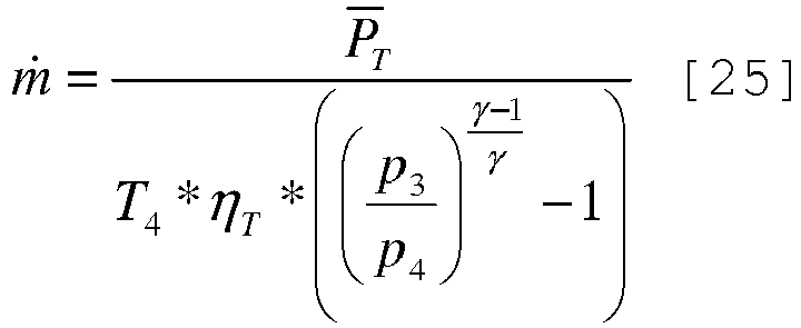
P T: durchschnittliche Leistung, die von der Turbine (13) geliefert wird;ṁ: Gasströmungsgeschwindigkeit, die durch die Turbine (13) strömt;ηT: interne Effizienz der Turbine (13);p3: Druck stromaufwärts der Turbine (13);p4: Druck stromabwärts der Turbine (13);T3: Temperatur stromaufwärts der Turbine (13);T4: Temperatur stromabwärts der Turbine (13); undγ: spezifische Wärme der Abgase, die durch die Turbine (13) strömen. - Verfahren nach einem der vorhergehenden Ansprüche und den weiteren Schritt des Einstellens der Menge von zu zirkulierendem Schmierfluid für den Turbolader (12) in Abhängigkeit von der durchschnittlichen Leistung (
P T), die von der Turbine (13) geliefert wird, umfassend. - Verfahren nach einem der vorhergehenden Ansprüche und den weiteren Schritt des Bestimmens der durchschnittlichen Leistung (
P C), die von dem Verdichter (14) geliefert wird, mittels der folgenden Formel umfassend:
P T: durchschnittlicher Wert der Leistung, die von der Turbine (13) geliefert wird;P C: durchschnittlicher Wert der Leistung, die von dem Verdichter (14) geliefert wird;ηC: interne Effizienz des Verdichters (14); undη0: organische Effizienz des Turboladers (12). - Verfahren nach Anspruch 16 und den weiteren Schritt des Bestimmens der Temperatur (T1) stromaufwärts des Verdichters (14) mittels der folgenden Formel umfassend:

P C: durchschnittlicher Wert der Leistung, die von dem Verdichter (14) geliefert wird;ṁ: Strömungsgeschwindigkeit der Gasmischung (Luft und mögliche rückgeführte Abgase), die durch den Verdichter (14) strömt;ηC: interne Effizienz des Verdichters (14);p1: Druck stromaufwärts des Verdichters (14);p2: Druck stromabwärts des Verdichters (14);T1: Temperatur stromaufwärts des Verdichters (14); undγ: spezifische Wärme der Gasmischung (Luft und mögliche rückgeführte Abgase), die durch den Verdichter (14) strömt. - Verfahren nach Anspruch 16 und den weiteren Schritt des Bestimmens des Drucks (131) stromaufwärts des Verdichters (14) mittels der folgenden Formel umfassend:

P C: durchschnittlicher Wert der Leistung, die von dem Verdichter (14) geliefert wird;ṁ: Strömungsgeschwindigkeit der Gasmischung (Luft und mögliche rückgeführte Abgase), die durch den Verdichter (14) strömt;ηC: interne Effizienz des Verdichters (14);p1: Druck stromaufwärts des Verdichters (14);p2: Druck stromabwärts des Verdichters (14);T1: Temperatur stromaufwärts des Verdichters (14); undγ: spezifische Wärme der Gasmischung (Luft und mögliche rückgeführte Abgase), die durch den Verdichter (14) strömt. - Verfahren nach Anspruch 16 und den weiteren Schritt des Bestimmens der Temperatur (T2) stromabwärts des Verdichters (14) mittels der folgenden Formel umfassend:

P C: durchschnittlicher Wert der Leistung, die von dem Verdichter (14) geliefert wird;m: Strömungsgeschwindigkeit der Gasmischung (Luft und mögliche rückgeführte Abgase), die durch den Verdichter (14) strömt;ηC: interne Effizienz des Verdichters (14);p1: Druck stromaufwärts des Verdichters (14);p2: Druck stromabwärts des Verdichters (14);T2: Temperatur stromabwärts des Verdichters (14); undγ: spezifische Wärme der Gasmischung (Luft und mögliche rückgeführte Abgase), die durch den Verdichter (14) strömt. - Verfahren nach Anspruch 16 und den weiteren Schritt des Bestimmens des Druckwerts (p2) stromabwärts des Verdichters (14) mittels der folgenden Formel umfassend:

P C: durchschnittlicher Wert der Leistung, die von dem Verdichter (14) geliefert wird;ṁ: Strömungsgeschwindigkeit der Gasmischung (Luft und mögliche rückgeführte Abgase), die durch den Verdichter (14) strömt;ηC: interne Effizienz des Verdichters (14);p1: Druck stromaufwärts des Verdichters (14);p2: Druck stromabwärts des Verdichters (14);T2: Temperatur stromabwärts des Verdichters (14); und
γ: spezifische Wärme der Gasmischung (Luft und mögliche rückgeführte Abgase), die durch den Verdichter (14) strömt. - Verfahren nach Anspruch 16 und den weiteren Schritt des Bestimmens der Strömungsgeschwindigkeit (m) der Gasmischung, die durch den Verdichter (14) strömt, mittels einer der zwei folgenden Formeln umfassend:


P C: durchschnittlicher Wert der Leistung, die von dem Verdichter (14) geliefert wird;ṁ: Strömungsgeschwindigkeit der Gasmischung (Luft und mögliche rückgeführte Abgase), die durch den Verdichter (14) strömt;ηC: interne Effizienz des Verdichters (14);p1: Druck stromaufwärts des Verdichters (14);p2: Druck stromabwärts des Verdichters (14);T1: Temperatur stromaufwärts des Verdichters (14);T2: Temperatur stromabwärts des Verdichters (14); undγ: spezifische Wärme der Gasmischung (Luft und mögliche rückgeführte Abgase), die durch den Verdichter (14) strömt.
Applications Claiming Priority (2)
| Application Number | Priority Date | Filing Date | Title |
|---|---|---|---|
| ITBO20140198 | 2014-04-07 | ||
| ITBO20140197 | 2014-04-07 |
Publications (2)
| Publication Number | Publication Date |
|---|---|
| EP2930337A1 EP2930337A1 (de) | 2015-10-14 |
| EP2930337B1 true EP2930337B1 (de) | 2018-12-05 |
Family
ID=52780489
Family Applications (1)
| Application Number | Title | Priority Date | Filing Date |
|---|---|---|---|
| EP15162691.8A Active EP2930337B1 (de) | 2014-04-07 | 2015-04-07 | Verfahren zur steuerung eines mit einem turbolader ausgestatteten, aufgeladenen verbrennungsmotors mittels schätzung der von der turbine des turboladers bereitgestellten durchschnittsleistung |
Country Status (2)
| Country | Link |
|---|---|
| US (1) | US9617931B2 (de) |
| EP (1) | EP2930337B1 (de) |
Families Citing this family (7)
| Publication number | Priority date | Publication date | Assignee | Title |
|---|---|---|---|---|
| US11053875B2 (en) | 2016-02-10 | 2021-07-06 | Garrett Transportation I Inc. | System and method for estimating turbo speed of an engine |
| CN108699966B (zh) * | 2016-03-08 | 2021-08-24 | 三菱重工发动机和增压器株式会社 | 增压器的喘振检测方法以及喘振检测装置 |
| US10371081B2 (en) * | 2017-05-02 | 2019-08-06 | Garrett Transportation I Inc. | System and methods for adaptively determining turbocharger speed |
| GB201719581D0 (en) * | 2017-11-24 | 2018-01-10 | Cummins Ltd | Method of designing and producing a turbine |
| US11560829B2 (en) * | 2020-01-02 | 2023-01-24 | Caterpillar Inc. | Recirculation system for a power system that includes a plurality of turbochargers |
| CN113494377B (zh) * | 2021-08-17 | 2022-06-28 | 柳州柳工挖掘机有限公司 | 一种电控发动机的节能控制方法和工程机械 |
| CN116658292B (zh) * | 2023-06-05 | 2026-03-20 | 潍柴动力股份有限公司 | 一种涡轮端功率监测方法、装置、电子设备和存储介质 |
Family Cites Families (15)
| Publication number | Priority date | Publication date | Assignee | Title |
|---|---|---|---|---|
| DE2141068C3 (de) | 1971-08-17 | 1979-09-06 | Akzo Gmbh, 5600 Wuppertal | Berührungslose Drehzahlmessung an Falschzwirnspindeln |
| SE500813C2 (sv) | 1993-01-22 | 1994-09-12 | Ase Autotest Ab | Förfarande för mätning av varvtalet på turboaggregat för motorer |
| DE102004010263A1 (de) | 2004-03-03 | 2005-09-22 | Daimlerchrysler Ag | Verfahren und Vorrichtung zur Drehzahlerfassung von Turboladern |
| WO2006137142A1 (ja) | 2005-06-23 | 2006-12-28 | Rion Co., Ltd. | エンジン回転数計測方法及びその装置 |
| AR052402A1 (es) | 2005-07-18 | 2007-03-21 | Vignolo Gustavo Gabriel | Metodo de medida de velocidad en turbo-alimentadores de motores de combustion interna mediante analisis de vibraciones, sofware y equipo para realizarlo |
| DE102005054736A1 (de) | 2005-11-17 | 2007-05-24 | Robert Bosch Gmbh | Verfahren zur Bestimmung der Drehzahl eines Abgasturboladers einer Brennkraftmaschine |
| US20090193896A1 (en) | 2008-01-31 | 2009-08-06 | Lawrence M Rose | Turbocharger rotational speed sensor |
| FR2932224B1 (fr) | 2008-06-04 | 2010-08-20 | Renault Sas | Systeme de regulation de la pression de suralimentation pour moteur a combustion interne a deux turbocompresseurs etages |
| FR2937379B1 (fr) | 2008-10-21 | 2014-07-18 | Renault Sas | Procede de diagnostic de l'etat d'un dispositif de suralimentation a turbocompresseur d'un moteur thermique de vehicule automobile |
| FR2941267B1 (fr) | 2009-01-22 | 2011-01-21 | Renault Sas | Procede et dispositif de determination de la pression en amont d'une turbine d'un turbocompresseur de suralimentation d'un moteur thermique. |
| FR2943727A1 (fr) * | 2009-03-30 | 2010-10-01 | Renault Sas | Procede, pour un turbocompresseur de suralimemntation, de determination d'une consigne de position d'un actionneur de by-pass. |
| IT1400362B1 (it) | 2010-06-03 | 2013-05-31 | Magneti Marelli Spa | Metodo di determinazione della velocita' di rotazione di un compressore in un motore a combustione interna |
| IT1400363B1 (it) | 2010-06-03 | 2013-05-31 | Magneti Marelli Spa | Metodo di determinazione della velocita' di rotazione di un compressore in un motore a combustione interna |
| DE102011016489A1 (de) | 2011-04-08 | 2012-10-11 | Continental Automotive Gmbh | Verfahren und Vorrichtung zum Messen der Drehzahl eines Turboverdichters und Kraftfahrzeug |
| FR2980525B1 (fr) | 2011-09-26 | 2013-08-30 | Renault Sa | Procede et systeme de diagnostic d'un groupe motopropulseur a deux turbocompresseurs etages. |
-
2015
- 2015-04-06 US US14/679,552 patent/US9617931B2/en active Active
- 2015-04-07 EP EP15162691.8A patent/EP2930337B1/de active Active
Non-Patent Citations (1)
| Title |
|---|
| None * |
Also Published As
| Publication number | Publication date |
|---|---|
| EP2930337A1 (de) | 2015-10-14 |
| US20150337747A1 (en) | 2015-11-26 |
| US9617931B2 (en) | 2017-04-11 |
Similar Documents
| Publication | Publication Date | Title |
|---|---|---|
| US9617931B2 (en) | Method to control a supercharged internal combustion engine provided with a turbocharger by means of an estimation of the average power delivered by the turbine of the turbocharger | |
| EP2392803B1 (de) | Verfahren zur Bestimmung der Rotationsgeschwindigkeit eines Turboladers einer Brennkraftmaschine | |
| Galindo et al. | On the effect of pulsating flow on surge margin of small centrifugal compressors for automotive engines | |
| US8291752B2 (en) | Method and device for monitoring an exhaust-gas turbocharger | |
| CN102418610B (zh) | 用于控制通过涡轮增压器增压的内燃机的速度的方法 | |
| EP2392804B1 (de) | Verfahren zur Bestimmung der Rotationsgeschwindigkeit eines Turboladers einer Brennkraftmaschine | |
| Galindo et al. | On-engine measurement of turbocharger surge limit | |
| Ravaglioli et al. | Automotive turbochargers power estimation based on speed fluctuation analysis | |
| US20090193896A1 (en) | Turbocharger rotational speed sensor | |
| Marelli et al. | Incipient Surge Detection in Automotive Turbocharger Compressors | |
| JP2014231830A (ja) | エンジン制御装置 | |
| Marelli et al. | Experimental investigation under unsteady flow conditions on turbocharger compressors for automotive gasoline engines | |
| US9297325B2 (en) | Systems and methods for compensating airflow determinations for air compressor bleed | |
| Ponti et al. | Non-intrusive methodology for estimation of speed fluctuations in automotive turbochargers under unsteady flow conditions | |
| JP2007321687A (ja) | ターボチャージャ付き内燃機関の制御装置 | |
| FR2974392B1 (fr) | Procede de diagnostic de defaillance d'un moteur suralimente et moteur suralimente | |
| US11660483B2 (en) | Sensor-based fire detection in a fluid conduit | |
| EP2295761B1 (de) | Verfahren und Vorrichtung zum Überwachen des Betriebs eines Verbrennungsmotors | |
| RU2351807C2 (ru) | Способ защиты газотурбинного двигателя от помпажа | |
| CN115405410A (zh) | 增压器的控制方法、装置、车辆及存储介质 | |
| Ponti et al. | Estimation Methodology for Automotive Turbochargers Speed Fluctuations due to Pulsating Flows | |
| Pai et al. | Air intake system noise in a turbocharged petrol engine during transient operation | |
| Gautam et al. | Comparative evaluation of turbochargers for high horsepower diesel-electric locomotives | |
| Gao et al. | Experimental investigation of characteristic frequency in compressor surge of a turbocharger | |
| Chen et al. | Study on the Fault Diagnosis Method of Compressor Instability by Fusing Multiple Time Domain Feature Parameters |
Legal Events
| Date | Code | Title | Description |
|---|---|---|---|
| PUAI | Public reference made under article 153(3) epc to a published international application that has entered the european phase |
Free format text: ORIGINAL CODE: 0009012 |
|
| AK | Designated contracting states |
Kind code of ref document: A1 Designated state(s): AL AT BE BG CH CY CZ DE DK EE ES FI FR GB GR HR HU IE IS IT LI LT LU LV MC MK MT NL NO PL PT RO RS SE SI SK SM TR |
|
| AX | Request for extension of the european patent |
Extension state: BA ME |
|
| 17P | Request for examination filed |
Effective date: 20160412 |
|
| GRAP | Despatch of communication of intention to grant a patent |
Free format text: ORIGINAL CODE: EPIDOSNIGR1 |
|
| STAA | Information on the status of an ep patent application or granted ep patent |
Free format text: STATUS: GRANT OF PATENT IS INTENDED |
|
| RIC1 | Information provided on ipc code assigned before grant |
Ipc: F02B 37/12 20060101ALI20180604BHEP Ipc: F02B 37/18 20060101ALI20180604BHEP Ipc: F02D 41/28 20060101ALN20180604BHEP Ipc: F02D 41/00 20060101AFI20180604BHEP |
|
| INTG | Intention to grant announced |
Effective date: 20180626 |
|
| GRAS | Grant fee paid |
Free format text: ORIGINAL CODE: EPIDOSNIGR3 |
|
| GRAA | (expected) grant |
Free format text: ORIGINAL CODE: 0009210 |
|
| GRAA | (expected) grant |
Free format text: ORIGINAL CODE: 0009210 |
|
| STAA | Information on the status of an ep patent application or granted ep patent |
Free format text: STATUS: THE PATENT HAS BEEN GRANTED |
|
| AK | Designated contracting states |
Kind code of ref document: B1 Designated state(s): AL AT BE BG CH CY CZ DE DK EE ES FI FR GB GR HR HU IE IS IT LI LT LU LV MC MK MT NL NO PL PT RO RS SE SI SK SM TR |
|
| REG | Reference to a national code |
Ref country code: GB Ref legal event code: FG4D |
|
| REG | Reference to a national code |
Ref country code: CH Ref legal event code: EP |
|
| REG | Reference to a national code |
Ref country code: AT Ref legal event code: REF Ref document number: 1073379 Country of ref document: AT Kind code of ref document: T Effective date: 20181215 |
|
| REG | Reference to a national code |
Ref country code: IE Ref legal event code: FG4D |
|
| REG | Reference to a national code |
Ref country code: DE Ref legal event code: R096 Ref document number: 602015020706 Country of ref document: DE |
|
| REG | Reference to a national code |
Ref country code: NL Ref legal event code: MP Effective date: 20181205 |
|
| REG | Reference to a national code |
Ref country code: AT Ref legal event code: MK05 Ref document number: 1073379 Country of ref document: AT Kind code of ref document: T Effective date: 20181205 |
|
| REG | Reference to a national code |
Ref country code: LT Ref legal event code: MG4D |
|
| PG25 | Lapsed in a contracting state [announced via postgrant information from national office to epo] |
Ref country code: FI Free format text: LAPSE BECAUSE OF FAILURE TO SUBMIT A TRANSLATION OF THE DESCRIPTION OR TO PAY THE FEE WITHIN THE PRESCRIBED TIME-LIMIT Effective date: 20181205 Ref country code: AT Free format text: LAPSE BECAUSE OF FAILURE TO SUBMIT A TRANSLATION OF THE DESCRIPTION OR TO PAY THE FEE WITHIN THE PRESCRIBED TIME-LIMIT Effective date: 20181205 Ref country code: NO Free format text: LAPSE BECAUSE OF FAILURE TO SUBMIT A TRANSLATION OF THE DESCRIPTION OR TO PAY THE FEE WITHIN THE PRESCRIBED TIME-LIMIT Effective date: 20190305 Ref country code: LT Free format text: LAPSE BECAUSE OF FAILURE TO SUBMIT A TRANSLATION OF THE DESCRIPTION OR TO PAY THE FEE WITHIN THE PRESCRIBED TIME-LIMIT Effective date: 20181205 Ref country code: ES Free format text: LAPSE BECAUSE OF FAILURE TO SUBMIT A TRANSLATION OF THE DESCRIPTION OR TO PAY THE FEE WITHIN THE PRESCRIBED TIME-LIMIT Effective date: 20181205 Ref country code: LV Free format text: LAPSE BECAUSE OF FAILURE TO SUBMIT A TRANSLATION OF THE DESCRIPTION OR TO PAY THE FEE WITHIN THE PRESCRIBED TIME-LIMIT Effective date: 20181205 Ref country code: BG Free format text: LAPSE BECAUSE OF FAILURE TO SUBMIT A TRANSLATION OF THE DESCRIPTION OR TO PAY THE FEE WITHIN THE PRESCRIBED TIME-LIMIT Effective date: 20190305 Ref country code: HR Free format text: LAPSE BECAUSE OF FAILURE TO SUBMIT A TRANSLATION OF THE DESCRIPTION OR TO PAY THE FEE WITHIN THE PRESCRIBED TIME-LIMIT Effective date: 20181205 |
|
| PG25 | Lapsed in a contracting state [announced via postgrant information from national office to epo] |
Ref country code: SE Free format text: LAPSE BECAUSE OF FAILURE TO SUBMIT A TRANSLATION OF THE DESCRIPTION OR TO PAY THE FEE WITHIN THE PRESCRIBED TIME-LIMIT Effective date: 20181205 Ref country code: AL Free format text: LAPSE BECAUSE OF FAILURE TO SUBMIT A TRANSLATION OF THE DESCRIPTION OR TO PAY THE FEE WITHIN THE PRESCRIBED TIME-LIMIT Effective date: 20181205 Ref country code: RS Free format text: LAPSE BECAUSE OF FAILURE TO SUBMIT A TRANSLATION OF THE DESCRIPTION OR TO PAY THE FEE WITHIN THE PRESCRIBED TIME-LIMIT Effective date: 20181205 Ref country code: GR Free format text: LAPSE BECAUSE OF FAILURE TO SUBMIT A TRANSLATION OF THE DESCRIPTION OR TO PAY THE FEE WITHIN THE PRESCRIBED TIME-LIMIT Effective date: 20190306 |
|
| PG25 | Lapsed in a contracting state [announced via postgrant information from national office to epo] |
Ref country code: NL Free format text: LAPSE BECAUSE OF FAILURE TO SUBMIT A TRANSLATION OF THE DESCRIPTION OR TO PAY THE FEE WITHIN THE PRESCRIBED TIME-LIMIT Effective date: 20181205 |
|
| PG25 | Lapsed in a contracting state [announced via postgrant information from national office to epo] |
Ref country code: PT Free format text: LAPSE BECAUSE OF FAILURE TO SUBMIT A TRANSLATION OF THE DESCRIPTION OR TO PAY THE FEE WITHIN THE PRESCRIBED TIME-LIMIT Effective date: 20190405 Ref country code: CZ Free format text: LAPSE BECAUSE OF FAILURE TO SUBMIT A TRANSLATION OF THE DESCRIPTION OR TO PAY THE FEE WITHIN THE PRESCRIBED TIME-LIMIT Effective date: 20181205 Ref country code: PL Free format text: LAPSE BECAUSE OF FAILURE TO SUBMIT A TRANSLATION OF THE DESCRIPTION OR TO PAY THE FEE WITHIN THE PRESCRIBED TIME-LIMIT Effective date: 20181205 |
|
| PG25 | Lapsed in a contracting state [announced via postgrant information from national office to epo] |
Ref country code: EE Free format text: LAPSE BECAUSE OF FAILURE TO SUBMIT A TRANSLATION OF THE DESCRIPTION OR TO PAY THE FEE WITHIN THE PRESCRIBED TIME-LIMIT Effective date: 20181205 Ref country code: SM Free format text: LAPSE BECAUSE OF FAILURE TO SUBMIT A TRANSLATION OF THE DESCRIPTION OR TO PAY THE FEE WITHIN THE PRESCRIBED TIME-LIMIT Effective date: 20181205 Ref country code: RO Free format text: LAPSE BECAUSE OF FAILURE TO SUBMIT A TRANSLATION OF THE DESCRIPTION OR TO PAY THE FEE WITHIN THE PRESCRIBED TIME-LIMIT Effective date: 20181205 Ref country code: IS Free format text: LAPSE BECAUSE OF FAILURE TO SUBMIT A TRANSLATION OF THE DESCRIPTION OR TO PAY THE FEE WITHIN THE PRESCRIBED TIME-LIMIT Effective date: 20190405 Ref country code: SK Free format text: LAPSE BECAUSE OF FAILURE TO SUBMIT A TRANSLATION OF THE DESCRIPTION OR TO PAY THE FEE WITHIN THE PRESCRIBED TIME-LIMIT Effective date: 20181205 |
|
| REG | Reference to a national code |
Ref country code: DE Ref legal event code: R097 Ref document number: 602015020706 Country of ref document: DE |
|
| PLBE | No opposition filed within time limit |
Free format text: ORIGINAL CODE: 0009261 |
|
| STAA | Information on the status of an ep patent application or granted ep patent |
Free format text: STATUS: NO OPPOSITION FILED WITHIN TIME LIMIT |
|
| PG25 | Lapsed in a contracting state [announced via postgrant information from national office to epo] |
Ref country code: DK Free format text: LAPSE BECAUSE OF FAILURE TO SUBMIT A TRANSLATION OF THE DESCRIPTION OR TO PAY THE FEE WITHIN THE PRESCRIBED TIME-LIMIT Effective date: 20181205 Ref country code: SI Free format text: LAPSE BECAUSE OF FAILURE TO SUBMIT A TRANSLATION OF THE DESCRIPTION OR TO PAY THE FEE WITHIN THE PRESCRIBED TIME-LIMIT Effective date: 20181205 |
|
| 26N | No opposition filed |
Effective date: 20190906 |
|
| REG | Reference to a national code |
Ref country code: CH Ref legal event code: PL |
|
| REG | Reference to a national code |
Ref country code: BE Ref legal event code: MM Effective date: 20190430 |
|
| GBPC | Gb: european patent ceased through non-payment of renewal fee |
Effective date: 20190407 |
|
| PG25 | Lapsed in a contracting state [announced via postgrant information from national office to epo] |
Ref country code: MC Free format text: LAPSE BECAUSE OF FAILURE TO SUBMIT A TRANSLATION OF THE DESCRIPTION OR TO PAY THE FEE WITHIN THE PRESCRIBED TIME-LIMIT Effective date: 20181205 Ref country code: LU Free format text: LAPSE BECAUSE OF NON-PAYMENT OF DUE FEES Effective date: 20190407 |
|
| PG25 | Lapsed in a contracting state [announced via postgrant information from national office to epo] |
Ref country code: CH Free format text: LAPSE BECAUSE OF NON-PAYMENT OF DUE FEES Effective date: 20190430 Ref country code: LI Free format text: LAPSE BECAUSE OF NON-PAYMENT OF DUE FEES Effective date: 20190430 Ref country code: GB Free format text: LAPSE BECAUSE OF NON-PAYMENT OF DUE FEES Effective date: 20190407 |
|
| PG25 | Lapsed in a contracting state [announced via postgrant information from national office to epo] |
Ref country code: BE Free format text: LAPSE BECAUSE OF NON-PAYMENT OF DUE FEES Effective date: 20190430 |
|
| PG25 | Lapsed in a contracting state [announced via postgrant information from national office to epo] |
Ref country code: TR Free format text: LAPSE BECAUSE OF FAILURE TO SUBMIT A TRANSLATION OF THE DESCRIPTION OR TO PAY THE FEE WITHIN THE PRESCRIBED TIME-LIMIT Effective date: 20181205 |
|
| PG25 | Lapsed in a contracting state [announced via postgrant information from national office to epo] |
Ref country code: IE Free format text: LAPSE BECAUSE OF NON-PAYMENT OF DUE FEES Effective date: 20190407 |
|
| PG25 | Lapsed in a contracting state [announced via postgrant information from national office to epo] |
Ref country code: CY Free format text: LAPSE BECAUSE OF FAILURE TO SUBMIT A TRANSLATION OF THE DESCRIPTION OR TO PAY THE FEE WITHIN THE PRESCRIBED TIME-LIMIT Effective date: 20181205 |
|
| PG25 | Lapsed in a contracting state [announced via postgrant information from national office to epo] |
Ref country code: HU Free format text: LAPSE BECAUSE OF FAILURE TO SUBMIT A TRANSLATION OF THE DESCRIPTION OR TO PAY THE FEE WITHIN THE PRESCRIBED TIME-LIMIT; INVALID AB INITIO Effective date: 20150407 Ref country code: MT Free format text: LAPSE BECAUSE OF FAILURE TO SUBMIT A TRANSLATION OF THE DESCRIPTION OR TO PAY THE FEE WITHIN THE PRESCRIBED TIME-LIMIT Effective date: 20181205 |
|
| PG25 | Lapsed in a contracting state [announced via postgrant information from national office to epo] |
Ref country code: MK Free format text: LAPSE BECAUSE OF FAILURE TO SUBMIT A TRANSLATION OF THE DESCRIPTION OR TO PAY THE FEE WITHIN THE PRESCRIBED TIME-LIMIT Effective date: 20181205 |
|
| PGFP | Annual fee paid to national office [announced via postgrant information from national office to epo] |
Ref country code: DE Payment date: 20250423 Year of fee payment: 11 |
|
| PGFP | Annual fee paid to national office [announced via postgrant information from national office to epo] |
Ref country code: IT Payment date: 20260319 Year of fee payment: 12 |
|
| PGFP | Annual fee paid to national office [announced via postgrant information from national office to epo] |
Ref country code: FR Payment date: 20260319 Year of fee payment: 12 |