EP2930492A2 - Wasserdampfmesseinrichtung und Sonde - Google Patents
Wasserdampfmesseinrichtung und Sonde Download PDFInfo
- Publication number
- EP2930492A2 EP2930492A2 EP14194585.7A EP14194585A EP2930492A2 EP 2930492 A2 EP2930492 A2 EP 2930492A2 EP 14194585 A EP14194585 A EP 14194585A EP 2930492 A2 EP2930492 A2 EP 2930492A2
- Authority
- EP
- European Patent Office
- Prior art keywords
- inlet
- air
- outlet device
- aircraft
- outlet
- Prior art date
- Legal status (The legal status is an assumption and is not a legal conclusion. Google has not performed a legal analysis and makes no representation as to the accuracy of the status listed.)
- Granted
Links
Images


Classifications
-
- G—PHYSICS
- G01—MEASURING; TESTING
- G01N—INVESTIGATING OR ANALYSING MATERIALS BY DETERMINING THEIR CHEMICAL OR PHYSICAL PROPERTIES
- G01N1/00—Sampling; Preparing specimens for investigation
- G01N1/02—Devices for withdrawing samples
- G01N1/22—Devices for withdrawing samples in the gaseous state
- G01N1/2273—Atmospheric sampling
-
- B—PERFORMING OPERATIONS; TRANSPORTING
- B64—AIRCRAFT; AVIATION; COSMONAUTICS
- B64D—EQUIPMENT FOR FITTING IN OR TO AIRCRAFT; FLIGHT SUITS; PARACHUTES; ARRANGEMENT OR MOUNTING OF POWER PLANTS OR PROPULSION TRANSMISSIONS IN AIRCRAFT
- B64D47/00—Equipment not otherwise provided for
-
- G—PHYSICS
- G01—MEASURING; TESTING
- G01N—INVESTIGATING OR ANALYSING MATERIALS BY DETERMINING THEIR CHEMICAL OR PHYSICAL PROPERTIES
- G01N21/00—Investigating or analysing materials by the use of optical means, i.e. using sub-millimetre waves, infrared, visible or ultraviolet light
- G01N21/01—Arrangements or apparatus for facilitating the optical investigation
- G01N21/03—Cuvette constructions
- G01N21/05—Flow-through cuvettes
-
- G—PHYSICS
- G01—MEASURING; TESTING
- G01N—INVESTIGATING OR ANALYSING MATERIALS BY DETERMINING THEIR CHEMICAL OR PHYSICAL PROPERTIES
- G01N21/00—Investigating or analysing materials by the use of optical means, i.e. using sub-millimetre waves, infrared, visible or ultraviolet light
- G01N21/17—Systems in which incident light is modified in accordance with the properties of the material investigated
- G01N21/25—Colour; Spectral properties, i.e. comparison of effect of material on the light at two or more different wavelengths or wavelength bands
- G01N21/27—Colour; Spectral properties, i.e. comparison of effect of material on the light at two or more different wavelengths or wavelength bands using photo-electric detection ; circuits for computing concentration
-
- G—PHYSICS
- G01—MEASURING; TESTING
- G01N—INVESTIGATING OR ANALYSING MATERIALS BY DETERMINING THEIR CHEMICAL OR PHYSICAL PROPERTIES
- G01N1/00—Sampling; Preparing specimens for investigation
- G01N1/02—Devices for withdrawing samples
- G01N1/22—Devices for withdrawing samples in the gaseous state
- G01N1/2273—Atmospheric sampling
- G01N2001/2279—Atmospheric sampling high altitude, e.g. rockets, balloons
-
- G—PHYSICS
- G01—MEASURING; TESTING
- G01N—INVESTIGATING OR ANALYSING MATERIALS BY DETERMINING THEIR CHEMICAL OR PHYSICAL PROPERTIES
- G01N1/00—Sampling; Preparing specimens for investigation
- G01N1/02—Devices for withdrawing samples
- G01N1/22—Devices for withdrawing samples in the gaseous state
- G01N2001/2285—Details of probe structures
Definitions
- the invention relates to an inlet and outlet device for air for measuring air supply of a system for determining the water vapor content or other gaseous admixtures of the ambient air of a flying aircraft.
- the inlet and outlet device can be used, for example, for the application in humidity measurements.
- Water vapor measuring devices for aircraft are generally known and typically have an inlet and outlet device (measuring probe), which serves to receive air from the environment of an aircraft and deliver it back to this. The air taken in by the inlet and outlet device is fed via a supply line to the actual measuring system, in which then the determination of the water vapor content of the air takes place.
- the measuring system referred to herein has a measuring chamber and is housed within the aircraft.
- air constantly flows through the inlet and outlet device and via the supply line into and through the measuring system with the measuring chamber and then via the discharge back to the inlet and outlet device and is there again delivered to the environment of the aircraft.
- the air flowing through the measuring system is also called measuring air.
- the aim of the invention is to provide an improved inlet and outlet device for air to the measuring air supply of a water vapor measuring device.
- an aircraft-mounted inlet and outlet device with an air inlet and an air outlet and a mounting portion for the attachment of the inlet and outlet device to an aircraft.
- the air inlet is spaced from the mounting portion such that the air inlet is outside a friction layer (boundary layer) around a surface of an aircraft when the inlet and outlet device is mounted on a flying aircraft.
- the air inlet is further connected to an inlet line, which has a supply line for a supply line to lead air entering the air inlet to a measuring chamber of a measuring system, which is in operation inside an aircraft.
- the air outlet is connected to a discharge port for discharge to guide air discharged from the metering chamber to the air outlet of the inlet and outlet devices.
- the inventors have recognized that it is advantageous to align the measuring air inlet against the flow. As a result, the risk can be reduced that it comes to a condensation, which would affect a water vapor measurement, ie the determination of the water vapor content of the measuring air. This follows from the fact that the temperature of the measuring air is increased and thus also the dew point difference of the measuring air. Heating of the measuring chamber can thus be dispensed with. Furthermore, the distance between the inlet opening and the aircraft surface reduces the contact with particles deposited on the aircraft outer skin. Furthermore, a mixing of the measuring air entering the measuring system can be prevented with optionally exiting the pressure cabin air. Furthermore, during flight operation of an aircraft, a pressure difference builds up between the air intake and the air outlet, which causes the flow of measuring air.
- the inlet and outlet device increases the density of the water vapor to be measured, whereby a lowering of the lower threshold of the measuring system takes place.
- the inlet and outlet device prevents supercooled water particles attach to the end face exposed to the flow of the aircraft inlet opening of the inlet and outlet device and thus endanger the flight safety. Inhomogeneities in the measurement gas density can be avoided because the measuring chamber in the measuring system may no longer have to be heated because of an otherwise possible risk of condensation.
- the inlet and outlet device should preferably be located within 3 m to 5 m behind the fuselage nose of the aircraft, so with the inlet opening outside the turbulent friction layer (boundary layer), which is located around the aircraft.
- the friction layer around the aircraft is the fluid dynamic boundary layer of the air flowing around the aircraft, due to the friction on an aircraft surface has a lower speed, than more distant air.
- Within the friction layer there is an impulse, heat and molecular or particle exchange with the wall surface of the aircraft. Since the inlet opening and thus the air inlet of the inlet and outlet device is arranged outside the friction layer, the measuring air entering into the inlet and outlet device is not influenced by properties of the wall surface, such as water wetting or a pressurized cabin leak upstream.
- the air during operation of the aircraft approximately at the relative velocity to the air inlet, which corresponds to the speed of the aircraft relative to the air, so the air speed.
- the ambient air impinging on the air intake is decelerated relative to the aircraft and thereby compressed, so that it adiabatically heated due to the congestion effect.
- the heating depends on the prevailing at the air inlet impact pressure, which in turn is speed-dependent.
- the measuring air is warmer than the ambient air, so that the risk of condensation is reduced.
- the inlet and outlet device according to the invention will also be referred to as Ram Air Intake for Water Vapor Measurement (RAIWaM) designated.
- RAIWaM Ram Air Intake for Water Vapor Measurement
- TAT total air temperature
- Conventional housings of this type for the air temperature measurement have no supply and discharge and therefore also no supply and discharge connections for connection to a measuring system for determining the water vapor content of the air.
- the aerodynamic and thermodynamic principle of operation the TAT package is described in Stickney et al. (1994); cf STICKNEY, TM; SHEDLOV, MW, THOMPSON, DI, 1994: Goodrich Total Temperature Sensors. Goodrich Corporation, Burnsville, Maine, USA.
- a possible variant is the housing of the type Rosemount ® BX 102 (or -BW) containing a removable temperature measuring element.
- the dust-related adiabatic heating of the measuring air is about 30 K at Mach 0.85 and at a height of 200 hPa. Even at lower speeds and at lower altitudes, adiabatic heating ensures that the air temperature always maintains a sufficient distance to the possible dew point , The only exception is when flying through clouds, which can result in the subsequent conversion of the water vapor mixture ratio in the relative humidity to a value of over 100%. Ultimately, this value can always be used as an indication of the presence of liquid or solid water particles, ie clouds or precipitation.
- the distance between the fastening section and the air inlet is between 50 mm and 150 mm, in particular between 80 mm and 100 mm.
- the aircraft-mounted inlet and outlet device for example, have a distance between the attachment section and the air inlet of 87 mm.
- the inlet and outlet device comprises a head part, a shaft and a flange.
- the shank extends between the flange and the head part and surrounds the inlet line.
- the head part has the air inlet on one end face.
- the flange forms the attachment portion for securing the entry and exit device to an aircraft.
- the head part may include a flow channel open on both sides, whose front, open end is the air inlet and which is flowed through during operation of air and is arranged so that it runs approximately parallel to the applied flow during operation.
- the flow channel can expand downstream of the air inlet initially in the inner cross-section and then rejuvenate to its open rear end forming an air outlet.
- the supply line can depart from an enlarged in the inner cross-section portion of the flow channel.
- the rear open end of the flow channel may have a smaller cross-section than the air inlet.
- the smaller cross section at the rear open end of the flow channel creates a Strömungsengstelle, in the flight condition of the aircraft at the entrance generated in the relatively speed-reduced route resulting pressure increase and thus the adiabatic heating of the measuring air.
- the sum of impact pressure and static pressure, ie the total pressure and thus also the adiabatic heating effect, are maintained along the flow channel or in the complete measuring section up to the flow throat.
- the aircraft-mounted inlet and outlet device preferably has a heated inlet opening.
- the probe heating preferably provided for this purpose serves to prevent ice formation and is preferably arranged on the end face of the inlet and outlet device.
- the aircraft-mounted inlet and outlet device additionally or alternatively may have a arranged on the supply line to the measuring chamber heater.
- the heater arranged on the supply line serves to heat the measuring air before it enters the actual measuring process of the measuring chamber and thus makes heating of the measuring air in the measuring chamber superfluous. It is possible that the adiabatic heating of the measuring air due to the accumulation effect is not considered sufficient to reliably prevent condensation.
- the heater can be used to heat the inlet pipe between RAIWaM and the measuring system to heat the measuring air.
- the supply line to the measuring chamber has a heater for heating air flowing through the supply line. By arranging the heating in the area of the supply line, it is possible to sufficiently heat the measuring air before it enters the measuring chamber so that the measuring air within the measuring chamber does not have to be heated and therefore has a homogeneous temperature.
- the measuring chamber of the measuring system is preferably an absorption measuring chamber, which allows a determination of the water vapor content, for example by means of absorption spectrometry.
- the RAIWaM for the measuring system type WVSS-II by SpectraSensors Inc., USA, it has a measuring chamber for the determination of the water vapor content by means of absorption spectrometry.
- Absorption spectrometry is a method for determining the water vapor content of the air.
- a measuring air column is illuminated by a measuring light beam whose absorption at a certain wavelength reflects the degree of water vapor density.
- a Physically conservative humidity parameters such as the water vapor mass mixing ratio
- the measurement of the pressure and the temperature of the chamber contents is required.
- the latter size can only be done at a finite number of measurement points within the chamber. For this reason, a homogeneous temperature field is required to obtain a representative temperature value. Direct chamber heating would conflict with this goal.
- the adiabatic warming effect of RAIWaM is an essential step in achieving the goal described.
- the RAIWaM's air inlet should be placed equidistant from the aircraft nose or fuselage nose, which is also required for the temperature sensors of the aircraft.
- the invention further relates to a water vapor measuring device with an inlet and outlet device and a supply line, a measuring system with a measuring chamber and a derivative.
- the supply line is connected to the inlet connection of the inlet and outlet device and an input of the measuring chamber tightly connected.
- the discharge line is connected to an outlet of the measuring chamber and the discharge connection of the inlet and outlet device.
- the measuring system is designed to determine the water vapor content of air in the measuring chamber.
- the measuring chamber is an absorption measuring chamber, which allows a determination of the humidity by means of an absorption spectrogram.
- TAT housing of RAIWaM can be heated (about 300 W) in order to prevent the risk of aircraft-endangering ice formation on the probe.
- RAIWaM has a TAT housing whose temperature measuring element is replaced by a specially made insert.
- the aerodynamic and thermodynamic conditions are described in Stickney et al. (1994).
- the invention therefore also relates to an insert for an inlet and outlet device.
- the insert has a storage sleeve as the first supply line section, which is designed for insertion into the shaft of the inlet and outlet device and which is dimensioned such that an inlet opening of the storage sleeve is located near the opening between the head part and the shaft of the inlet and outlet device.
- the congestion sleeve is connected via an inlet line as a second supply line section with a supply connection for the supply line.
- the insert preferably has a discharge jacket tube surrounding the inlet line, which is connected to a discharge connection for the discharge.
- the insert further comprises means for releasably connecting the insert to the shaft of the inlet and outlet device.
- the outlet casing pipe may further comprise outlet openings or slots which are arranged at or near the transition between the first feed line section and the second feed line section and which are designed to remove a fluid, for example the measurement air, from the outlet casing pipe.
- the first supply line section has a larger cross section than the sum of the cross sections of the second supply line section and of the outlet pipe surrounding the second supply section.
- Fig. 1 shows a view of a water vapor measuring device 10 with serving as RAIWaM inlet and outlet device 12 with a serving as a boom shaft 20.
- an insert 40 is inserted, by means of which the inlet and outlet device 12 via a supply line 14 and a derivative 18 is connected to a measuring chamber 16 of a measuring system.
- the insert 40 is removable.
- the steam measuring device 10 thus has a measuring probe 12 as RAIWaM in the form of a TAT housing.
- the water vapor measuring device 10 has a first air duct as a supply line 14, a measuring chamber 16 with the actual water vapor measuring system and a second air duct as a derivative 18, which are successively flowed through by measuring air in operation.
- the supply line 14 extends from the TAT housing 12 (measuring probe 12) to a measuring chamber inlet of the measuring chamber 16.
- the discharge line 18 extends from a measuring chamber outlet of the measuring chamber 16 back to the TAT housing 12.
- the TAT housing 12 has a shank 20 as a boom, at one end of which an aerodynamically shaped head portion 21 having an air inlet or air inlet 22 is provided and the other end is a mounting end in the form of a flange 24 for attachment to an aircraft.
- the shaft 20 is dimensioned so that the air inlet 22 is an air inlet in the area of the first few meters behind the aircraft nose in flight outside a fluid-dynamic boundary layer around the aircraft in flight state, to which the inlet and outlet device 12 is attached.
- Fig. 3 illustrates the internal structure and function of the entire measuring system including RAIWaM.
- the head portion 21 includes a flow channel 26 open on both sides, whose front open end is the air inlet 22.
- the rear open end of the flow channel 26 forms an air outlet 28.
- the inner cross-section of the flow channel 26 extends first and then decreases towards the air outlet 28 out again.
- the air outlet 28 has a smaller cross section than the air inlet 22nd
- the supply line 14 goes there from the flow channel 26, where it has an enlarged inner cross-section.
- the drain 18 is fluidly connected to an air outlet 30 disposed at a trailing edge of the stem 20
- the flow channel 26 is aligned with respect to the shaft 20 and with respect to the flange 24 so that it runs in operation approximately parallel to the direction of flow of the ambient air.
- ambient air impinging on the air inlet 22 accumulates at the air inlet 22 and is heated adiabatically by this accumulation effect. Accordingly, the measuring air is heated relative to the ambient air.
- the heated measuring air flows out of the flow channel 26 into the feed line 14 and through it into the measuring system with the measuring chamber 16. There, the water vapor measurement takes place by means of absorption spectrometry. Subsequently, the measuring air from the measuring chamber 16 and the measuring chamber exit out into the second air duct 18 and is guided by this back to the discharge port 50.
- the air within the head portion is deflected at a right angle to the baffle, the actual inlet opening for the temperature probe or possibly a continuation.
- the head part is provided with holes, which by the suction effect of the outer flow around the friction layer of the inner flow aspirate and thus reduce it. This ensures that the deflected flow part upstream receives largely no contact with the housing wall.
- the undisturbed adiabatic accumulation effect can occur at the inlet of the stowage sleeve. Its heating effect on the sensor located in the sleeve is compensated in a simple calculation method.
- the congestion effect is achieved by narrow outlet openings at the flow end of the sleeve, where there is a relative negative pressure aerodynamically on the outside of the sleeve.
- the airspeed outside is reduced from up to 300 m / s to a few m / s.
- the almost complete total pressure is achieved as the sum of the static (ambient) pressure and the impact pressure.
- the end faces of the inlet openings facing the flow are provided with an electrical probe heater 32.
- the first supply line 14 is provided with a heater 34.
- the shaft 20 causes a distance of the air inlet 22 from an aircraft surface formed by the aircraft outer skin 36, which is dimensioned so that the air inlet 22 is outside a fluid dynamic boundary layer around the aircraft outer skin 36 and thus flows freely at a speed which is the speed of Aircraft relative to the air (Airspeed) corresponds.
- the distance is preferably between 50mm and 150mm, for example between 80mm and 100mm.
- an insert 40 is provided, which is inserted into the TAT housing 12 and forms both a part of the supply line 14 and a part of the discharge line 18 and thus the supply and removal of measuring air to the measuring system with the measuring chamber 16 is used.
- Fig. 3 shows the insert 40 both in a schematic representation in the cross-sectional view of the RAIWaM ( Fig. 3a ) as well as in a perspective partial view ( Fig. 3b ).
- the insert 40 is designed such that an inlet opening 42 of the insert 40 directly adjoins the flow channel 26. At the inlet opening 42 of the insert 40, the almost full impact pressure is applied. The inlet opening 42 is at the same time the input to the supply line 14.
- a part of the insert 40 in the figure thus forms a first supply section 44 in the form of a storage sleeve, to which a second supply line 46 connects in a straight line as an inlet line of the insert 40, opposite of the serving as a first feed section dam sleeve 44 has a reduced diameter and leads to a supply port 48 to which the further supply line 14 is connected, which finally leads to the measuring chamber 16.
- the insert 40 also forms part of the discharge line 18.
- a discharge connection 50 is provided which leads to a discharge section 52, which is arranged as a jacket tube coaxially around the second supply line section 46, and into an exit slot 54 opens, which is located where the first supply line section 44 of larger diameter, so the congestion sleeve, in the second supply line section 46 (ie, the supply line) merges with a smaller diameter.
- exhausted measuring air enters an inner cavity 56 of the shaft 20, which in turn is fluidly connected to the air outlet 30 on the shaft 20.
- the inner cavity 56 is also fluidly connected to the flow channel 26 and is traversed by air entering the air inlet 22.
- the insert 40 is designed so that its inlet or retaining sleeve 44 is geometrically identical to that of a temperature measuring insert used in TAT housings.
- the air that has entered opens into a symmetry-axis-central inlet line, which leads directly to the connecting piece of the measuring air supply line of the actual measuring system.
- the backflowing measuring air is guided from the connection piece of the measuring system outlet via the jacket tube 52 around the inlet line to the outlet slot 54, which is located at the insert 40 exactly at the point where the outlet openings are located at the geometrically and aerodynamically identical temperature measuring insert of the TAT housing ,
- the air emerging from this slot passes through the inner cavity 56 to the rear exit opening which forms the air outlet 30.
- the pressure gradient between the inlet opening 42 at the front end of the retaining sleeve 44 and the outlet slot 54 ensures the flow of the measuring air.
- results in a laboratory verified flow rate between 3 and 5 liters per minute. This is more than sufficient for conventional measuring systems. A separate pump operation is not required.
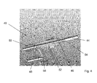
- the amount of air and thus also the pressure in the air guidance system from the inlet can be adjusted via a set screw 58 (see cross section in fig Fig. 4 ).
- the set screw causes an adjustable constriction. This constriction ensures that the impact pressure is maintained throughout the measuring system.
- the flow rate can be adapted to the requirements of the measuring process.
- Fig. 4 shows a partially cutaway perspective view of the insert 40.
- the entire insert 40 is inserted into the TAT housing 12 of the RAIWaM and removable again.
Landscapes
- Health & Medical Sciences (AREA)
- Life Sciences & Earth Sciences (AREA)
- Physics & Mathematics (AREA)
- General Health & Medical Sciences (AREA)
- Immunology (AREA)
- Pathology (AREA)
- General Physics & Mathematics (AREA)
- Chemical & Material Sciences (AREA)
- Analytical Chemistry (AREA)
- Biochemistry (AREA)
- Engineering & Computer Science (AREA)
- Biomedical Technology (AREA)
- Molecular Biology (AREA)
- Mathematical Physics (AREA)
- Spectroscopy & Molecular Physics (AREA)
- Theoretical Computer Science (AREA)
- Aviation & Aerospace Engineering (AREA)
- Measuring Fluid Pressure (AREA)
- Measuring Temperature Or Quantity Of Heat (AREA)
- Details Of Measuring And Other Instruments (AREA)
- Investigating Or Analyzing Materials Using Thermal Means (AREA)
Abstract
Description
- Die Erfindung betrifft eine Ein- und Auslaufvorrichtung für Luft zur Messluftversorgung eines Systems zum Bestimmen des Wasserdampfgehaltes oder anderer gasförmiger Beimengungen der Umgebungsluft eines fliegenden Flugzeuges.
- In der folgenden Beschreibung dieser Erfindung wird vornehmlich auf das Gas "Wasserdampf" Bezug genommen. Die Ein- und Auslaufvorrichtung kann beispielsweise für die Anwendung bei Feuchtemessungen eingesetzt werden. Wasserdampfmesseinrichtungen für Flugzeuge sind grundsätzlich bekannt und besitzen typischerweise eine Ein- und Auslaufvorrichtung (Messsonde), die dazu dient, Luft aus der Umgebung eines Luftfahrzeugs aufzunehmen und wieder an diese abzugeben. Die von der Ein- und Auslaufvorrichtung aufgenommene Luft wird über eine Zuleitung dem eigentlichen Messsystem zugeführt, in dem dann die Bestimmung des Wasserdampfgehaltes der Luft erfolgt. Das Messsystem, auf das hier Bezug genommen wird, weist eine Messkammer auf und ist innerhalb des Luftfahrzeugs untergebracht. Im Betrieb des Luftfahrzeuges strömt permanent Luft durch die Ein- und Auslaufvorrichtung und über die Zuleitung in und durch das Messsystem mit der Messkammer und anschließend über die Ableitung wieder zurück zu der Ein- und Auslaufvorrichtung und wird dort wieder an die Umgebung des Luftfahrzeuges abgegeben. Die durch das Messsystem strömende Luft wird auch als Messluft bezeichnet.
- Ziel der Erfindung ist es eine verbesserte Ein- und Auslaufvorrichtung für Luft zur Messluftversorgung einer Wasserdampfmessseinrichtung bereitzustellen.
- Erfindungsgemäß wird dieses Ziel von einer flugzeugmontierbaren Ein- und Auslaufvorrichtung mit einem Lufteinlauf und einem Luftauslass sowie einem Befestigungsabschnitt für die Befestigung der Ein- und Auslaufvorrichtung an einem Flugzeug erreicht. Der Lufteinlauf hat einen solchen Abstand von dem Befestigungsabschnitt, dass der Lufteinlauf sich außerhalb einer Reibungsschicht (Grenzschicht) um eine Oberfläche eines Flugzeuges befindet, wenn die Ein- und Auslaufvorrichtung an einem fliegenden Flugzeug montiert ist. Der Lufteinlauf ist des Weiteren mit einer Einlaufleitung verbunden, die einen Zuleitungsanschluss für eine Zuleitung aufweist, um in den Lufteinlauf eintretende Luft zu einer Messkammer eines Messsystems zu führen, das sich im Betrieb im Inneren eines Flugzeuges befindet. Weiterhin ist der Luftauslass mit einem Ableitungsanschluss für eine Ableitung verbunden, um aus der Messkammer austretende Luft zum Luftauslass der Ein- und Auslaufvorrichtung zu führen.
- Die Erfinder haben erkannt, dass es vorteilhaft ist, den Messlufteinlauf entgegen der Anströmung auszurichten. Hierdurch kann die Gefahr verringert werden, dass es zu einer Kondensatbildung kommt, die eine Wasserdampfmessung, also die Bestimmung des Wasserdampfgehaltes der Messluft, beeinträchtigen würde. Dies folgt daraus, dass die Temperatur der Messluft erhöht ist und damit auch die Taupunktdifferenz der Messluft. Eine Beheizung der Messkammer kann damit entfallen. Weiterhin wird durch einem Abstand der Eintrittsöffnung zur Flugzeugoberfläche der Kontakt mit an der Flugzeugaußenhaut angelagerten Partikeln verringert. Des Weiteren kann eine Vermischung der in das Messsystem eintretenden Messluft mit gegebenenfalls aus der Druckkabine austretender Luft verhindert werden. Weiterhin baut sich während des Flugbetriebs eines Flugzeuges eine Druckdifferenz zwischen Lufteinlauf und Luftauslass auf, die den Durchfluss von Messluft bewirkt. Des Weiteren erhöht die Ein- und Auslaufvorrichtung die Dichte des zu messenden Wasserdampfes, wodurch eine Erniedrigung der unteren Ansprechschwelle des Messsystems erfolgt. Die Ein- und Auslaufvorrichtung verhindert, dass sich unterkühlte Wasserpartikel an dem der Flugzeugströmung ausgesetzten Stirnfläche der Eintrittsöffnung der Ein- und Auslaufvorrichtung anlagern und so die Flugsicherheit gefährden. Inhomogenitäten in der Messgasdichte können vermieden werden, weil die Messkammer im Messsystem gegebenenfalls nicht mehr wegen einer sonst möglichen Kondensationsgefahr beheizt werden muss.
- Die Ein- und Auslaufvorrichtung soll vorzugsweise innerhalb von 3 m bis 5 m hinter der Rumpfnase des Luftfahrzeugs, also mit der Eintrittsöffnung außerhalb der turbulenten Reibungsschicht (Grenzschicht) angeordnet sein, die sich um das Luftfahrzeug befindet. Die Reibungsschicht um das Luftfahrzeug ist die fluiddynamische Grenzschicht der das Flugzeug umströmenden Luft, in Folge der Reibung an einer Flugzeugoberfläche eine geringere Geschwindigkeit aufweist, als weiter entfernte Luft. Innerhalb der Reibungsschicht findet ein Impuls-, Wärme- und Molekular- beziehungsweise Partikelaustausch mit der Wandfläche des Luftfahrzeuges statt. Da die Eintrittsöffnung und damit der Lufteinlauf der Ein- und Auslaufvorrichtung außerhalb der Reibungsschicht angeordnet ist, unterliegt die in die Ein- und Auslaufvorrichtung eintretende Messluft keiner Beeinflussung durch Eigenschaften der Wandfläche, wie beispielsweise einer Wasserbenetzung oder eines Druckkabinenlecks stromaufwärts.
- In Folge des erfindungsgemäß vorgesehenen Abstands des Lufteinlaufs von der Außenoberfläche des Luftfahrzeugs trifft die Luft im Betrieb des Luftfahrzeugs in etwa mit der Relativgeschwindigkeit auf den Lufteinlauf, die der Geschwindigkeit des Luftfahrzeugs relativ zur Luft, also der Air-Speed, entspricht. Im Betrieb wird die auf den Lufteinlauf treffende Umgebungsluft relativ zum Luftfahrzeug abgebremst und dadurch verdichtet, sodass sie sich bedingt durch den Staueffekt adiabatisch erwärmt. Die Erwärmung hängt dabei von dem am Lufteinlauf herrschenden Auftreffdruck ab, der wiederum geschwindigkeitsabhängig ist. Im Ergebnis ist die Messluft wärmer als die Umgebungsluft, sodass die Gefahr von Kondensatbildung verringert ist. Dadurch kann auf eine weitere Erwärmung der Messluft weitgehend und insbesondere in der Messkammer verzichtet werden.
- Die erfindungsgemäße Ein- und Auslaufvorrichtung wird im Folgenden auch als
Ram Air Intake for Water Vapour Measurement (RAIWaM)
bezeichnet. Der Einfachheit halber wird im Folgenden das Akronym RAIWaM verwendet. - Der äußere Ummantelungsteil von RAIWaM kann ein für Luftfahrzeuge gewöhnliches Gesamttemperaturmessgehäuse sein, das im Folgenden auch als TAT-Gehäuse bezeichnet wird (TAT = Total Air Temperature), wie es bisher für Lufttemperaturmessungen verwendet wird. Konventionelle Gehäuse dieser Art für die Lufttemperaturmessung besitzen jedoch keine Zuleitung und Ableitung und mithin auch keine Zuleitungs- und Ableitungsanschlüsse zum Anschluss an ein Messsystem für die Bestimmung des Wasserdampfgehaltes der Luft. Das aerodynamische und thermodynamische Funktionsprinzip der TAT-Gehäuse ist in Stickney et al. (1994) dargelegt; c.f. STICKNEY, T. M.; SHEDLOV, M. W., THOMPSON, D. I., 1994: Goodrich Total Temperature Sensors. Goodrich Corporation, Burnsville, Maine, USA. Eine mögliche Gehäusevariante ist die des Typs Rosemount® 102 BX (oder -BW), die ein entnehmbares Temperaturmesselement enthält.
- Die staubedingte adiabatische Erwärmung der Messluft beträgt bei Mach 0,85 und in einer Höhe von 200 hPa ca. 30 K. Selbst bei kleineren Geschwindigkeiten und in geringeren Höhen sorgt die adiabatische Erwärmung dafür, dass die Lufttemperatur zu dem möglichen Taupunkt immer einen ausreichenden Abstand behält. Die einzige Ausnahme ist beim Durchfliegen von Wolken gegeben, was bei dem nachträglichen Umrechnen des Wasserdampfmischungsverhältnisses in die relative Feuchte zu einem Wert von über 100 % führen kann. Letztlich kann dieser Wert immer als Hinweis auf das Vorhandensein von flüssigen oder festen Wasserpartikeln, sprich Wolken oder Niederschlag, verwendet werden.
- In einer möglichen Ausgestaltung der flugzeugmontierbaren Ein- und Auslaufvorrichtung beträgt der Abstand zwischen Befestigungsabschnitt und Lufteinlauf zwischen 50 mm und 150 mm, insbesondere zwischen 80 mm und 100 mm. Die flugzeugmontierbare Ein- und Auslaufvorrichtung kann beispielsweise einen Abstand zwischen Befestigungsabschnitt und Lufteinlauf von 87 mm haben.
- In einer bevorzugten Ausgestaltung der flugzeugmontierbaren Ein- und Auslaufvorrichtung weist die Ein- und Auslaufvorrichtung ein Kopfteil, einen Schaft und einen Flansch auf. Der Schaft erstreckt sich zwischen Flansch und Kopfteil und umschließt die Einlaufleitung. Das Kopfteil weist an einer Stirnseite den Lufteinlauf auf. Der Flansch bildet den Befestigungsabschnitt zum Befestigen der Ein- und Auslaufvorrichtung an einem Flugzeug. Weiterhin kann das Kopfteil einen beidseitig offenen Strömungskanal einschließen, dessen vorderes, offenes Ende der Lufteinlauf ist und der im Betrieb von Luft durchströmt wird und so angeordnet ist, dass er im Betrieb annähernd parallel zur anliegenden Strömung verläuft. Des Weiteren kann sich der Strömungskanal stromabwärts des Lufteinlaufes zunächst im Innenquerschnitt erweitern und anschließend zu seinem offenen hinteren, einen Luftauslauf bildenden Ende wieder verjüngen. Die Zuleitung kann von einem im Innenquerschnitt erweiterten Abschnitt des Strömungskanals abgehen. Zudem kann das hintere offene Ende des Strömungskanals einen kleineren Querschnitt haben, als der Lufteinlauf. Der kleinere Querschnitt am hinteren offenen Ende des Strömungskanals erzeugt eine Strömungsengstelle, die im Flugzustand des Luftfahrzeuges die am Eintritt in die relativ geschwindigkeitsreduzierte Strecke entstehende Druckerhöhung und somit die adiabatische Erwärmung der Messluft erzeugt. Die Summe aus Auftreffdruck und statischem Druck, also der Gesamtdruck und damit auch der adiabatische Erwärmungseffekt bleiben entlang des Strömungskanals bzw. in der kompletten Messstrecke bis zu der Strömungsengstelle erhalten.
- Die flugzeugmontierbare Ein- und Auslaufvorrichtung weist vorzugsweise eine beheizte Eintrittsöffnung auf. Die hierzu vorzugsweise vorgesehene Sondenheizung dient zur Vermeidung von Eisbildung und ist vorzugsweise an der Stirnfläche der Ein- und Auslaufvorrichtung angeordnet.
- Weiterhin kann die flugzeugmontierbare Ein- und Auslaufvorrichtung zusätzlich oder alternativ eine an der Zuleitung zur Messkammer angeordnete Heizung aufweisen. Die an der Zuleitung angeordnete Heizung dient zur Erwärmung der Messluft, bevor sie in den eigentlichen Messprozess der Messkammer eintritt und macht somit einer Erwärmung der Messluft in der Messkammer überflüssig. Es ist möglich, dass die durch den Staueffekt bedingte adiabatische Erwärmung der Messluft als noch nicht ausreichend angesehen wird, eine Kondensatbildung sicher zu vermeiden. In diesem Fall kann die Heizung zur Erwärmung der Einlaufleitung zwischen RAIWaM und dem Messsystem dienen, um so die Messluft zu erwärmen. Entsprechend kann es gemäß einer bevorzugten Ausführungsvariante vorgesehen sein, dass die Zuleitung zur Messkammer eine Heizung zum Erwärmen von durch die Zuleitung strömende Luft aufweist. Indem die Heizung im Bereich der Zuleitung angeordnet ist, ist es möglich die Messluft vor dem Eintreten in die Messkammer ausreichend zu erwärmen, sodass die Messluft innerhalb der Messkammer nicht beheizt werden muss und deswegen eine homogene Temperatur aufweist.
- Die Messkammer des Messsystems ist vorzugsweise eine Absorptionsmesskammer, die eine Bestimmung des Wasserdampfgehalts zum Beispiel mittels Absorptionsspektrometrie erlaubt.
- In einem beispielhaften Anwendungsfall des RAIWaM für das Messsystem Typ WVSS-II von SpectraSensors Inc., USA hat dieses eine Messkammer für die Bestimmung des Wasserdampfgehalts mittels Absorptionsspektrometrie. Die Absorptionsspektrometrie ist ein Verfahren zum Bestimmen des Wasserdampfgehaltes der Luft. Eine Messluftsäule wird von einem Messlichtstrahl durchleuchtet dessen Absorption bei einer bestimmten Wellenlänge das Maß der Wasserdampfdichte wiedergibt. Für die Berechnung eines physikalisch konservativen Luftfeuchteparameters, wie z.B. dem Wasserdampfmassenmischungsverhältnis ist neben der Wasserdampfdichte auch die Messung des Druckes und der Temperatur des Kammerinhaltes erforderlich. Letztere Größe kann nur an einer endlichen Zahl von Messpunkten innerhalb der Kammer erfolgen. Aus diesem Grund ist ein homogenes Temperaturfeld erforderlich, um einen repräsentativen Temperaturwert zu erhalten. Eine direkte Kammerbeheizung würde mit diesem Ziel in Konflikt stehen. Der adiabatische Erwärmungseffekt des RAIWaM ist für das Erreichen des beschriebenen Ziels ein wesentlicher Schritt.
- Die mit der Ein- und Auslaufvorrichtung und ihren möglichen Ausgestaltungen erreichten bzw. erreichbaren Gewinne sind:
- die geräteinterne Kondensation kann vermieden oder zumindest verringert werden, ohne gesonderte Beheizung des Kernteils des Messsystems, also im Fall eines optischen Verfahrens der Absorptions- oder Streuungsmesskammer
- da der Lufteintritt von RAIWaM bei aerodynamisch korrekter Positionierung auf dem Flugzeugrumpf außerhalb der Reibungsschicht liegt,
- > können im Anströmbereich vorhandene Kabinenlecks keine Störungen erzeugen,
- > können im Anströmbereich Wasser- oder Eisanlagerungen an der Außenhaut des Flugzeuges ohne Einfluss (keine Memory-Effekte) bleiben,
- wegen des Staueffektes kann eine gegenüber der Außenluft deutlich erhöhte Wasserdampfdichte (um bis zu 50 %) im Endeffekt für eine Erniedrigung der unteren Ansprechschwelle des Messverfahrens sorgen.
- Um die spezifizierten Eigenschaften (Lufteintrittspunkt außerhalb der Grenzschicht des Flugkörpers) zu haben, sollte der Lufteinlauf des RAIWaM in dem gleichen Abstand zur Flugzeugnase bzw. Rumpfnase untergebracht werden, der auch für die Temperatursensoren des Flugzeuges einzuhalten ist.
- Die Erfindung betrifft des Weiteren eine Wasserdampfmesseinrichtung mit einer Ein- und Auslaufvorrichtung sowie einer Zuleitung, einem Messsystem mit einer Messkammer und einer Ableitung. Die Zuleitung ist mit dem Zuleitungsanschluss der Ein- und Auslaufvorrichtung und einem Eingang der Messkammer dicht verbunden. Die Ableitung ist mit einem Ausgang der Messkammer und dem Ableitungsanschluss der Ein- und Auslaufvorrichtung verbunden. Das Messsystem ist ausgebildet den Wasserdampfgehalt von Luft in der Messkammer zu bestimmen.
- In einer bevorzugten Ausgestaltung der Wasserdampfmesseinrichtung ist die Messkammer eine Absorptionsmesskammer, die eine Bestimmung der Luftfeuchtigkeit mittels eines Absorptionsspektrogramms erlaubt.
- Die Erfindung schließt die Erkenntnis ein, dass bekannte Wasserdampfmesseinrichtungen folgende Nachteile haben:
- Die in den Lufteinlauf einströmende Luft ist zuvor mit der stromaufwärts gelegenen Rumpfoberfläche in Kontakt. Abhängig von deren Wasser- oder Eisbenetzung und von der Temperatur können nicht reproduzierbare Trägheits-Effekte entstehen (auch Memory-Effekt genannt).
- Die Messluft kann wegen verschiedentlich auftretender kleiner Lecks im stromaufwärts gelegenen Teil der Druckkabine durch die wasserdampfangereicherte Innenluft der Kabine kontaminiert sein. Die Lecks können im Lauf der Alterung des Flugzeuges an Türen, Fenstern, Klappen, Steckverbindern, Fahrwerksschacht und allen Übergängen von Bauteilen des Rumpfes entstehen, beispielsweise durch Ermüdungserscheinungen an den Stoßnähten der Aluminium-bleche. Diese Lecks sind für den Flugbetrieb bedeutungslos, aber für die Wasserdampfmessung fatal. Der Effekt nimmt mit der Höhe zu, also mit zunehmender Druckdifferenz zwischen Kabine und Umgebung. Der Effekt ist vornehmlich flugzeugtypen- und - altersabhängig. Es können aber auch individuelle Unterschiede typengleicher Flugzeuge auftreten. Eine Kalibrierbarkeit dieser immer möglichen Fehlereffekte ist prinzipiell nicht gegeben.
- Der früheren Ein- und Auslaufvorrichtung, dem sogenannten "Air Sampler" (Teil des Systems WVSS-II von SpectraSensors Inc., USA) zugrundeliegendes Konstruktionsziel, nämlich der Erhalt des Flugzeugumgebungsdruckes (statischer Druck), hat sich als Nachteil erwiesen. Bei einer relativen Feuchte der Umgebungsluft von nahe 100 % kann im inneren Teil des Messluftweges (Schläuche, Übergangsstücke und Absorptionskammer) eine den Messprozess entscheidend störende Kondensation auftreten. Hierfür gibt es zwei Gründe:
- Der Air Sampler kann an einer Stelle des Flugzeuges untergebracht sein, die einen umströmungsbedingten Unterdruck hat. Allein schon die damit unmittelbar verbundene adiabatische Abkühlung erreicht bei höheren Feuchtegraden schnell den Taupunkt.
- Die thermische Trägheit der Innenwände der Eingangsluftführung und der Absorptionskammer sorgt bei Sinkflug, also dem Übergang von kälteren zu wärmeren Bedingungen, für die Unterschreitung des Taupunktes.
- Die beiden letztgenannten Effekte sorgen oftmals für eine unerwünschte Kondensatbildung innerhalb der Messluftleitungen und vor allem innerhalb der Absorptionsmesskammer.
- Es ist vorteilhaft, wenn das TAT-Gehäuse von RAIWaM beheizbar ist (ca. 300 W), um auf diese Weise die Gefahr der flugzeuggefährdenden Eisbildung an der Sonde zu unterbinden.
- RAIWaM weist gemäß einer bevorzugten Ausführungsvariante ein TAT-Gehäuse auf, dessen Temperaturmesselement durch einen speziell angefertigten Einsatz ersetzt wird. Die aerodynamischen und thermodynamischen Bedingungen sind bei Stickney et al. (1994) beschrieben. Die Erfindung betrifft daher auch einen Einsatz für eine Ein- und Auslaufvorrichtung. Der Einsatz weist eine Stauhülse als ersten Zuleitungsabschnitt auf, die zum Einsetzen in den Schaft der Ein- und Auslaufvorrichtung ausgebildet ist und die so bemessen ist, dass eine Eintrittsöffnung der Stauhülse sich nahe der Öffnung zwischen Kopfteil und Schaft der Ein- und Auslaufvorrichtung befindet. Die Stauhülse ist über eine Einlaufleitung als zweitem Zuleitungsabschnitt mit einem Zuleitungsanschluss für die Zuleitung verbunden.
- Der Einsatz weist vorzugsweise ein die Einlaufleitung umgebendes Auslaufmantelrohr auf, das mit einem Ableitungsanschluss für die Ableitung verbunden ist. Der Einsatz weist des Weiteren Mittel zum lösbaren Verbinden des Einsatzes mit dem Schaft der Ein- und Auslaufvorrichtung auf. Das Auslaufmantelrohr kann weiterhin Austrittsöffnungen oder - schlitze aufweisen, die am oder nahe dem Übergang zwischen erstem Zuleitungsabschnitt und zweitem Zuleitungsabschnitt angeordnet sind und die ausgebildet sind, ein Fluid, beispielsweise die Messluft aus dem Auslaufmantelrohr, abzuführen. In einer bevorzugten Ausgestaltung des Einsatzes hat der erste Zuleitungsabschnitt einen größeren Querschnitt als die Summe der Querschnitte des zweiten Zuleitungsabschnitts und des den zweiten Zuleitungsabschnitt umgebenden Auslaufmantelrohrs. Im eingesetzten Zustand des Einsatzes in den Schaft der Ein- und Auslaufvorrichtung wird so ein Raum um das Auslaufmantelrohr erzeugt, der eine Abfuhr der Luft aus den Austrittsschlitzen begünstigt.
- Die Erfindung soll nun in Bezug auf ein Ausführungsbeispiel anhand der Figuren näher erläutert werden. Von den Figuren ist
- Fig. 1:
- eine schematische Ansicht einer Wasserdampfmesseinrichtung mit einer Ein- und Auslaufvorrichtung für Luft mit einem Einsatz zum Anschluss an eine Wasserdampfmesssystem
- Fig. 2:
- eine perspektivische Außenansicht der Ein- und Auslaufvorrichtung
- Fig. 3a:
- eine geschnittene Darstellung des Prinzipschemas der Ein- und Auslaufvorrichtung zur Erläuterung der Funktion des RAIWaM
- Fig. 3b
- eine perspektivische Teilansicht eines Einsatzes und
- Fig. 4:
- eine teilweise geschnittene, perspektivische Ansicht des Einsatzes in der Ein- und Auslaufvorrichtung als RAIWaM zum Anschluss der Ein- und Auslaufvorrichtung an ein im Flugzeuginneren angeordnetes Messsystem.
-
Fig. 1 zeigt eine Ansicht einer Wasserdampfmesseinrichtung 10 mit einer als RAIWaM dienenden Ein- und Auslaufvorrichtung 12 mit einem als Ausleger dienenden Schaft 20. In die Ein- und Auslaufvorrichtung 12 ist ein Einsatz 40 eingesetzt, mittels dessen die Ein- und Auslaufvorrichtung 12 über eine Zuleitung 14 und eine Ableitung 18 mit einer Messkammer 16 eines Messsystems verbunden ist. Der Einsatz 40 ist entnehmbar. - Die Wasserdampfmesseinrichtung 10 weist somit eine Messsonde 12 als RAIWaM in Form eines TAT-Gehäuses auf. Außerdem weist die Wasserdampfmesseinrichtung 10 eine erste Luftführung als Zuleitung 14, eine Messkammer 16 mit dem eigentlichen Wasserdampfmesssystem und eine zweite Luftführung als Ableitung 18 auf, die im Betrieb nacheinander von Messluft durchströmt werden. Die Zuleitung 14 erstreckt sich von dem TAT-Gehäuse 12 (Messsonde 12) zu einem Messkammereingang der Messkammer 16. Die Ableitung 18 erstreckt sich von einem Messkammerausgang der Messkammer 16 zurück zum TAT-Gehäuse 12.
- Das TAT-Gehäuse 12 weist einen Schaft 20 als Ausleger auf, an dessen einen Ende ein aerodynamisch geformtes Kopfteil 21 mit einem Lufteintritt oder Lufteinlauf 22 vorgesehen ist und dessen anderes Ende ein Befestigungsende in Form eines Flansches 24 zur Befestigung an einem Luftfahrzeug ist.
- Der Schaft 20 ist so bemessen, dass sich der Lufteinlauf 22 als Lufteintritt im Bereich der ersten wenigen Meter hinter der Flugzeugnase im Flugbetrieb außerhalb einer fluid-dynamischen Grenzschicht um das im Flugzustand befindliche Luftfahrzeug ist, an dem die Ein- und Auslaufvorrichtung 12 befestigt ist.
-
Fig. 3 illustriert den inneren Aufbau und die Funktion der gesamten Messeinrichtung inklusive RAIWaM. Der Kopfteil 21 schließt einen beidseitig offenen Strömungskanals 26 ein, dessen vorderes offenes Ende der Lufteinlauf 22 ist. Das hintere offene Ende des Strömungskanals 26 bildet einen Luftauslauf 28. Zwischen Lufteinlauf 22 und Luftauslauf 28 erweitert sich der Innenquerschnitt des Strömungskanals 26 zunächst und nimmt dann zum Luftauslauf 28 hin wieder ab. Der Luftauslauf 28 hat einen geringeren Querschnitt als der Lufteinlauf 22. - Die Zuleitung 14 geht dort von dem Strömungskanal 26 ab, wo dieser einen vergrößerten Innenquerschnitt aufweist. Die Ableitung 18 ist mit einem Luftauslass 30 fluid-verbunden, der an einer Hinterkante des Schafts 20 angeordnet ist
- Der Strömungskanal 26 ist bezüglich des Schaftes 20 bzw. bezüglich dessen Flansch 24 so ausgerichtet, dass er im Betrieb etwa parallel zur Anströmrichtung der Umgebungsluft verläuft. Im Betrieb auf den Lufteinlauf 22 auftreffende Umgebungsluft staut sich am Lufteinlauf 22 und erwärmt sich durch diesen Staueffekt adiabatisch. Entsprechend ist die Messluft gegenüber der Umgebungsluft erwärmt. Die erwärmte Messluft strömt aus dem Strömungskanal 26 in die Zuleitung 14 und durch diese hindurch in das Messsystem mit der Messkammer 16. Dort findet die Wasserdampfmessung mittels Absorptionsspektrometrie statt. Anschließend tritt die Messluft aus der Messkammer 16 und deren Messkammerausgang heraus in die zweite Luftführung 18 und wird von dieser wieder zurück zum Ableitungsanschluss 50 geführt.
- Somit wird die Luft innerhalb des Kopfteils in einem rechten Winkel zu der Stauhülse, der eigentlichen Einlassöffnung für die Temperaturmesssonde oder ggf. eine Weiterführung umgelenkt. Stromaufwärts vor diesem Umlenkpunkt ist der Kopfteil mit Löchern versehen, die durch die Sogwirkung der äußeren Umströmung die Reibungsschicht der Innen-strömung absaugen und damit verkleinern. Damit wird erreicht, dass der umgelenkte Strömungsteil stromaufwärts weitestgehend keinen Kontakt mit der Gehäusewand erhält. Somit kann bei der ursprünglichen Verwendung als Temperaturmessvorrichtung der ungestörte adiabatische Staueffekt am Eintritt der Stauhülse entstehen. Dessen Erwärmungseffekt auf den in der Hülse befindlichen Sensor wird in einem einfachen Rechenverfahren kompensiert. Der Staueffekt wird durch enge Austrittsöffnungen am strömungsmäßigen Ende der Hülse erreicht, wo an der Hülsenaußenseite aerodynamisch bedingt ein relativer Unterdruck herrscht. Die Luftgeschwindigkeit ganz außerhalb wird von bis zu 300 m/s auf wenige m/s reduziert. Damit wird der nahezu vollständige Gesamtdruck als die Summe aus dem statischen (Umgebungs-) Druck und dem Auftreffdruck erreicht.
- Zur Vermeidung von Eisbildung an der als Messsonde dienenden Ein- und Auslaufvorrichtung 12 sind die der Strömung zugewandten Stirnflächen der Eintrittsöffnungen mit einer elektrischen Sondenheizung 32 vorgesehen. Für eine gegebenenfalls nötige weitere Erwärmung der Messluft ist die erste Zuleitung 14 mit einer Heizung 34 versehen.
- Der Schaft 20 bewirkt einen Abstand des Lufteinlaufs 22 von einer von der Flugzeugaußenhaut 36 gebildeten Flugzeugoberfläche, der so bemessen ist, dass sich der Lufteinlauf 22 außerhalb einer fluiddynamischen Grenzschicht um die Flugzeugaußenhaut 36 befindet und somit frei mit einer Geschwindigkeit angeströmt wird, die der Geschwindigkeit des Flugzeugs relativ zur Luft (Airspeed) entspricht. Der Abstand beträgt vorzugsweise zwischen 50mm und 150mm, beispielsweise zwischen 80mm und 100mm.
- Anstelle einer sonst vorgesehenen Temperatursonde ist ein Einsatz 40 vorgesehen, der in das TAT-Gehäuse 12 eingesetzt ist und sowohl einen Teil der Zuleitung 14 als auch einen Teil der Ableitung 18 bildet und somit der Zu- und Abfuhr von Messluft zu dem Messsystem mit der Messkammer 16 dient.
Fig. 3 zeigt den Einsatz 40 sowohl in einer schematischen Darstellung in der Querschnittsansicht des RAIWaM (Fig. 3a ) als auch in einer perspektivischen Teilansicht (Fig. 3b ). - Der Einsatz 40 ist so gestaltet, dass eine Eintrittsöffnung 42 des Einsatzes 40 unmittelbar an den Strömungskanal 26 angrenzt. An der Eintrittsöffnung 42 des Einsatzes 40 liegt der nahezu volle Auftreffdruck an. Die Eintrittsöffnung 42 ist gleichzeitig der Eingang zur Zuleitung 14. Ein in der Figur oberer Teil des Einsatzes 40 bildet somit einen ersten Zuleitungsabschnitt 44 in Form einer Stauhülse, an den sich in gerader Linie ein zweiter Zuleitungsabschnitt 46 als Einlaufleitung des Einsatzes 40 anschließt, die gegenüber der als erstem Zuleitungsabschnitt dienenden Stauhülse 44 einen verringerten Durchmesser aufweist und zu einem Zuleitungsanschluss 48 führt, an dem die weitere Zuleitung 14 angeschlossen ist, die schließlich zur Messkammer 16 führt.
- Der Einsatz 40 bildet außerdem einen Teil der Ableitung 18. Zum Anschluss an die übrige Ableitung 18 ist ein Ableitungsanschluss 50 vorgesehen, der zu einem Ableitungsabschnitt 52 führt, der als Mantelrohr koaxial um den zweiten Zuleitungsabschnitt 46 herum angeordnet ist, und der in einen Austrittsschlitz 54 mündet, der sich dort befindet, wo der erste Zuleitungsabschnitt 44 mit größerem Durchmesser, also die Stauhülse, in den zweiten Zuleitungsabschnitt 46 (d.h. die Zuleitung) mit geringerem Durchmesser übergeht. Aus dem Austrittsschlitz 54 tritt abfließende Messluft in einen inneren Hohlraum 56 des Schafts 20 ein, der wiederum mit dem Luftauslass 30 am Schaft 20 fluidverbunden ist. Der innere Hohlraum 56 ist außerdem mit dem Strömungskanal 26 fluidverbunden und wird von in den Lufteinlauf 22 eintretender Luft durchströmt. Diese strömt unter anderem außen an dem ersten Zuleitungsabschnitt 44 mit vergrößertem Durchmesser vorbei und wird dort aufgrund einer Verengung infolge eines relativ geringen Abstandes zwischen einer Außenwand des ersten Zuleitungsabschnittes 44 und einer Innenwand des inneren Hohlraumes 56 beschleunigt, sodass sich ein gegenüber dem im Ableitungsabschnitt 52 herrschenden statischen Druck niedrigerer statischer Druck ergibt.
- Der Einsatz 40 ist so gestaltet, dass dessen Eintritts- oder Stauhülse 44 zu der eines in TAT-Gehäusen verwendeten Temperaturmesseinsatzes geometrisch identisch ist. Die eingetretene Luft mündet in eine symmetrieachsenzentrale Einlaufleitung, die direkt zum Anschlussstück der Messluftzuleitung des eigentlichen Messsystems führt.
- Die zurückfließende Messluft wird von dem Anschlussstück des Messsystemauslaufes über das Mantelrohr 52 um die Einlaufleitung zu dem Austrittsschlitz 54 geführt, der an dem Einsatz 40 genau an der Stelle ist, an der sich an dem geometrisch und aerodynamisch identischen Temperaturmesseinsatz des TAT-Gehäuses die Austrittsöffnungen befinden. Die aus diesem Schlitz austretende Luft geht über den inneren Hohlraum 56 zur rückwärtigen Austrittsöffnung, die den Luftauslass 30 bildet. Das Druckgefälle zwischen der Eintrittsöffnung 42 am Stirnende der Stauhülse 44 und dem Austrittsschlitz 54 sorgt für den Fluss der Messluft. Letztendlich ergibt sich eine im Labor nachgeprüfte Fließgeschwindigkeit zwischen 3 und 5 Litern pro Minute. Das ist für übliche Messsysteme mehr als ausreichend. Ein gesonderter Pumpenbetrieb ist nicht erforderlich.
- Die Menge Luft und damit auch der Druck im Luftführungssystem ab dem Eintritt sind über eine Stellschraube 58 einstellbar (siehe Schnittbild in
Fig. 4 ). Die Stellschraube bewirkt eine justierbare Engstelle Diese Engstelle sorgt dafür, dass der Auftreffdruck im gesamten Messsystem gehalten wird. Die Durchströmungsmenge kann den Anforderungen des Messprozesses angepasst werden. -
Fig. 4 zeigt eine teilweise geschnittene, perspektivische Ansicht des Einsatzes 40. Der gesamte Einsatz 40 ist in das TAT-Gehäuse 12 des RAIWaM einsetzbar und wieder entfernbar. -
- 10
- Wasserdampfmesseinrichtung
- 12
- Ein- und Auslaufvorrichtung, Messsonde/TAT-Gehäuse,
- 14
- Zuleitung
- 16
- Messkammer
- 18
- Ableitung
- 20
- Schaft/Ausleger
- 21
- Kopfteil
- 22
- Lufteinlauf/Lufteintritt
- 24
- Befestigungsende/ Befestigungsabschnitt /Flansch
- 26
- Strömungskanal
- 28
- Luftauslauf
- 30
- Luftauslass
- 32
- Sondenheizung
- 34
- Heizung
- 36
- Flugzeugaußenhaut
- 40
- Einsatz
- 42
- Eintrittsöffnung
- 44
- Stauhülse, erster Zuleitungsabschnitt
- 46
- Einlaufleitung, zweiter Zuleitungsabschnitt
- 48
- Zuleitungsanschluss
- 50
- Ableitungsanschluss
- 52
- Ableitungsabschnitt/ Mantelrohr
- 54
- Austrittsschlitz
- 56
- Hohlraum
- 58
- Stellschraube
Claims (15)
- Flugzeugmontierbare Ein- und Auslaufvorrichtung (12) mit einem Lufteinlauf (22) und einem Luftauslass (30) sowie einem Befestigungsabschnitt (24) für die Befestigung der Ein- und Auslaufvorrichtung (12) an einem Flugzeug, wobei der Lufteinlauf (22) einen solchen Abstand von dem Befestigungsabschnitt (24) hat, dass der Lufteinlauf (22) sich außerhalb einer Reibungsschicht (Grenzschicht) um eine Oberfläche eines Flugzeuges befindet, wenn die Ein- und Auslaufvorrichtung (12) an einem fliegenden Flugzeug montiert ist, wobei der Lufteinlauf (22) mit einer Einlaufleitung (46) verbunden ist, die einen Zuleitungsanschluss (48) für eine Zuleitung (14) aufweist, um in den Lufteinlauf (22) eintretende Luft zu einer Messkammer (16) eines Messsystems zu führen, das sich im Betrieb im Inneren eines Flugzeuges befindet, und wobei der Luftauslass (30) mit einem Ableitungsanschluss (50) für eine Ableitung (18) verbunden ist, um aus der Messkammer (16) austretende Luft zum Luftauslass (30) der Ein- und Auslaufvorrichtung (12) zu führen.
- Flugzeugmontierbare Ein- und Auslaufvorrichtung (12) gemäß Anspruch 1, wobei der Abstand zwischen Befestigungsabschnitt (24) und Lufteinlauf (22) zwischen 50 mm und 150 mm, insbesondere zwischen 80 mm und 100 mm beträgt.
- Flugzeugmontierbare Ein- und Auslaufvorrichtung (12) gemäß Anspruch 1 oder 2, wobei die Ein- und Auslaufvorrichtung (12) ein Kopfteil (21), einen Schaft (20) und einen Flansch (24) aufweist, wobei sich der Schaft (20) zwischen Flansch (24) und Kopfteil (21) erstreckt und die Einlaufleitung (46) umschließt und wobei das Kopfteil (21) an einer Stirnseite den Lufteinlauf (22) aufweist und wobei der Flansch (24) den Befestigungsabschnitt (24) zum Befestigen der Ein- und Auslaufvorrichtung (12) an einem Flugzeug bildet.
- Flugzeugmontierbare Ein- und Auslaufvorrichtung (12) gemäß Anspruch 3, wobei das Kopfteil (21) einen beidseitig offenen Strömungskanal (26) einschließt, dessen vorderes, offenes Ende der Lufteinlauf (22) ist und der im Betrieb von Luft durchströmt wird und so angeordnet ist, dass er im Betrieb annähernd parallel zur anliegenden Strömung verläuft.
- Flugzeugmontierbare Ein- und Auslaufvorrichtung (12) gemäß Anspruch 4, wobei sich der Strömungskanal (26) stromabwärts des Lufteinlaufes (22) zunächst im Innenquerschnitt erweitert und anschließend zu seinem offenen hinteren, einen Luftauslauf (28) bildenden Ende wieder verjüngt, wobei die Zuleitung (14) von einem im Innenquerschnitt erweiterten Abschnitt des Strömungskanals (26) abgeht.
- Flugzeugmontierbare Ein- und Auslaufvorrichtung (12) gemäß Anspruch 4 oder 5, wobei das hintere offene Ende des Strömungskanals (26) einen kleineren Querschnitt hat, als der Lufteinlauf (22).
- Flugzeugmontierbare Ein- und Auslaufvorrichtung (12) gemäß wenigstens einem der Ansprüche 1 bis 6, wobei die Ein- und Auslaufvorrichtung (12) eine Sondenheizung (32) aufweist.
- Flugzeugmontierbare Ein- und Auslaufvorrichtung (12) gemäß Anspruch 7, wobei die Sondenheizung (32) an einer Stirnfläche der Ein- und Auslaufvorrichtung (12) und/oder am Übergang oder nahe dem Übergang zwischen Lufteinlauf (22) und Einlaufleitung (46) angeordnet ist.
- Flugzeugmontierbare Ein- und Auslaufvorrichtung (12) gemäß wenigstens einem der Ansprüche 1 bis 8, wobei die Ein- und Auslaufvorrichtung (12) eine an der Zuleitung (14) zur Messkammer (16) angeordnete Heizung (34) aufweist.
- Wasserdampfmesseinrichtung (10) mit einer Ein- und Auslaufvorrichtung (12) gemäß Anspruch 1, sowie einer Zuleitung (14), einem Messsystem mit einer Messkammer (16) und einer Ableitung (18), wobei die Zuleitung (14) mit dem Zuleitungsanschluss (48) der Ein- und Auslaufvorrichtung (12) und einem Eingang der Messkammer (16) dicht verbunden ist und die Ableitung (18) mit einem Ausgang der Messkammer (16) und dem Ableitungsanschluss (50) der Ein- und Auslaufvorrichtung (12) verbunden ist und wobei das Messsystem ausgebildet ist, den Wasserdampfgehalt von Luft in der Messkammer (16) zu bestimmen.
- Wasserdampfmesseinrichtung (10) gemäß Anspruch 10, wobei die Messkammer (16) eine Absorptionsmesskammer ist, die eine Bestimmung der Luftfeuchtigkeit mittels eines Absorptionsspektrogramms erlaubt.
- Einsatz (40) für eine Ein- und Auslaufvorrichtung (12) gemäß Anspruch 2, wobei der Einsatz (40) eine Stauhülse (44) als ersten Zuleitungsabschnitt (44) aufweist, die zum Einsetzen in den Schaft (20) der Ein- und Auslaufvorrichtung (12) ausgebildet ist und die so bemessen ist, dass eine Eintrittsöffnung (42) der Stauhülse (44) sich nahe der Öffnung zwischen Kopfteil (21) und Schaft (20) der Ein- und Auslaufvorrichtung (12) befindet, wobei die Stauhülse (44) über eine Einlaufleitung (46) als zweitem Zuleitungsabschnitt (46) mit einem Zuleitungsanschluss (48) für die Zuleitung (14) verbunden ist.
- Einsatz (40) gemäß Anspruch 12, wobei der Einsatz (40) ein die Einlaufleitung (46) umgebendes Auslaufmantelrohr (52) aufweist, das mit einem Ableitungsanschluss (50) für die Ableitung verbunden ist, und wobei der Einsatz (40) Mittel zum lösbaren Verbinden des Einsatzes (40) mit dem Schaft (20) der Ein- und Auslaufvorrichtung (12) aufweist.
- Einsatz (40) gemäß Anspruch 13, wobei das Auslaufmantelrohr (52) Austrittsschlitze (54) aufweist, die am oder nahe dem Übergang zwischen erstem Zuleitungsabschnitt (44) und zweitem Zuleitungsabschnitt (46) angeordnet sind und die ausgebildet sind ein Fluid aus dem Auslaufmantelrohr (52) abzuführen.
- Einsatz (40) gemäß wenigstens einem der Ansprüche 12 bis 14, wobei der erste Zuleitungsabschnitt (44) einen größeren Querschnitt aufweist als die Summe der Querschnitte des zweiten Zuleitungsabschnitts (46) und des den zweiten Zuleitungsabschnitt (46) umgebenden Auslaufmantelrohrs (52).
Priority Applications (8)
| Application Number | Priority Date | Filing Date | Title |
|---|---|---|---|
| PL14194585T PL2930492T3 (pl) | 2014-04-11 | 2014-11-24 | Przyrząd do pomiaru pary wodnej |
| EP14194585.7A EP2930492B1 (de) | 2014-04-11 | 2014-11-24 | Wasserdampfmesseinrichtung |
| EP15801753.3A EP3224592B1 (de) | 2014-04-11 | 2015-11-24 | Einsatz für eine ein- und auslaufvorrichtung |
| US15/529,138 US10564073B2 (en) | 2014-04-11 | 2015-11-24 | Insert for an inflow and outflow apparatus |
| ES15801753T ES2897924T3 (es) | 2014-04-11 | 2015-11-24 | Inserto para un dispositivo de entrada y salida |
| PL15801753T PL3224592T3 (pl) | 2014-04-11 | 2015-11-24 | Wkładka dla zespołu wlotowego i wylotowego |
| CN201580072905.2A CN107110745B (zh) | 2014-04-11 | 2015-11-24 | 用于进出气设备的嵌件 |
| PCT/EP2015/077573 WO2016083422A1 (de) | 2014-11-24 | 2015-11-24 | Einsatz für eine ein- und auslaufvorrichtung |
Applications Claiming Priority (2)
| Application Number | Priority Date | Filing Date | Title |
|---|---|---|---|
| EP14164515 | 2014-04-11 | ||
| EP14194585.7A EP2930492B1 (de) | 2014-04-11 | 2014-11-24 | Wasserdampfmesseinrichtung |
Publications (3)
| Publication Number | Publication Date |
|---|---|
| EP2930492A2 true EP2930492A2 (de) | 2015-10-14 |
| EP2930492A3 EP2930492A3 (de) | 2015-12-23 |
| EP2930492B1 EP2930492B1 (de) | 2020-09-23 |
Family
ID=50473212
Family Applications (2)
| Application Number | Title | Priority Date | Filing Date |
|---|---|---|---|
| EP14194585.7A Active EP2930492B1 (de) | 2014-04-11 | 2014-11-24 | Wasserdampfmesseinrichtung |
| EP15801753.3A Active EP3224592B1 (de) | 2014-04-11 | 2015-11-24 | Einsatz für eine ein- und auslaufvorrichtung |
Family Applications After (1)
| Application Number | Title | Priority Date | Filing Date |
|---|---|---|---|
| EP15801753.3A Active EP3224592B1 (de) | 2014-04-11 | 2015-11-24 | Einsatz für eine ein- und auslaufvorrichtung |
Country Status (5)
| Country | Link |
|---|---|
| US (1) | US10564073B2 (de) |
| EP (2) | EP2930492B1 (de) |
| CN (1) | CN107110745B (de) |
| ES (2) | ES2837851T3 (de) |
| PL (2) | PL2930492T3 (de) |
Cited By (3)
| Publication number | Priority date | Publication date | Assignee | Title |
|---|---|---|---|---|
| EP3413025A1 (de) * | 2017-06-08 | 2018-12-12 | Rosemount Aerospace Inc. | Gesamtlufttemperatursonde mit reduzierter sensorvereisungsdurchflusskanalgeometrie |
| US10203253B2 (en) | 2016-02-10 | 2019-02-12 | Rosemount Aerospace Inc. | Total air temperature probe with efficient particle pass through |
| US10852203B2 (en) | 2018-06-15 | 2020-12-01 | Rosemount Aerospace Inc. | Total air temperature probe with concave flow path transitions to outlet |
Families Citing this family (1)
| Publication number | Priority date | Publication date | Assignee | Title |
|---|---|---|---|---|
| US9689755B2 (en) * | 2013-10-22 | 2017-06-27 | Rosemount Aerospace Inc. | Temperature sensors |
Family Cites Families (16)
| Publication number | Priority date | Publication date | Assignee | Title |
|---|---|---|---|---|
| US4092123A (en) * | 1977-08-08 | 1978-05-30 | Mine Safety Appliances Company | Dual purpose personal dosimeter |
| DE4100363A1 (de) * | 1991-01-04 | 1992-07-09 | Ver Kraftwerks Ag Peitz Nieder | Anordnung einer rauchgas-probenahme- und -analysen-vorrichtung fuer eine feuerung |
| CH682188A5 (de) * | 1991-07-18 | 1993-07-30 | Asea Brown Boveri | |
| US6857328B1 (en) * | 2002-05-23 | 2005-02-22 | Sample probe for aerosol sampling apparatus | |
| US7014357B2 (en) * | 2002-11-19 | 2006-03-21 | Rosemount Aerospace Inc. | Thermal icing conditions detector |
| US20040177683A1 (en) * | 2003-03-13 | 2004-09-16 | Ice Paul A. | Total air temperature probe providing a secondary sensor measurement chamber |
| US7339165B2 (en) * | 2004-07-09 | 2008-03-04 | Hamilton Sundstrand Corporation | Dual outlet pyrolyzer for biological agent detection system |
| US7156552B2 (en) * | 2004-09-07 | 2007-01-02 | University Corporation For Atmospheric Research | Temperature sensor system for mobile platforms |
| US7357572B2 (en) | 2005-09-20 | 2008-04-15 | Rosemount Aerospace Inc. | Total air temperature probe having improved deicing heater error performance |
| CN101437580B (zh) * | 2006-04-26 | 2012-05-16 | 联合技术公司 | 在飞机中递送氧气的系统 |
| FR2908882B1 (fr) * | 2006-11-17 | 2008-12-26 | Thales Sa | Dispositif de mesure de la pression totale d'un ecoulement et procede mettant en oeuvre le dispositif |
| US7828477B2 (en) | 2007-05-14 | 2010-11-09 | Rosemount Aerospace Inc. | Aspirated enhanced total air temperature probe |
| AT13312U1 (de) * | 2010-04-29 | 2013-10-15 | Norsk Inst For Luftforskning | System und Verfahren zum Erkennen ungünstiger atmosphärischer Bedingungen vor einem Flugzeug |
| CN102252875B (zh) | 2011-06-01 | 2013-04-03 | 山东大学 | 一种飞机外挂式大气气溶胶航空导流罩 |
| US9658117B2 (en) | 2012-08-18 | 2017-05-23 | Rosemount Aerospace Inc. | Total air temperature probes for reducing deicing heater error |
| US9829395B2 (en) * | 2012-12-13 | 2017-11-28 | Rosemount Aerospace Inc. | Air temperature sensor arrangement for a vehicle and method of measuring air temperature |
-
2014
- 2014-11-24 PL PL14194585T patent/PL2930492T3/pl unknown
- 2014-11-24 EP EP14194585.7A patent/EP2930492B1/de active Active
- 2014-11-24 ES ES14194585T patent/ES2837851T3/es active Active
-
2015
- 2015-11-24 EP EP15801753.3A patent/EP3224592B1/de active Active
- 2015-11-24 PL PL15801753T patent/PL3224592T3/pl unknown
- 2015-11-24 CN CN201580072905.2A patent/CN107110745B/zh active Active
- 2015-11-24 US US15/529,138 patent/US10564073B2/en active Active
- 2015-11-24 ES ES15801753T patent/ES2897924T3/es active Active
Non-Patent Citations (1)
| Title |
|---|
| None |
Cited By (4)
| Publication number | Priority date | Publication date | Assignee | Title |
|---|---|---|---|---|
| US10203253B2 (en) | 2016-02-10 | 2019-02-12 | Rosemount Aerospace Inc. | Total air temperature probe with efficient particle pass through |
| EP3413025A1 (de) * | 2017-06-08 | 2018-12-12 | Rosemount Aerospace Inc. | Gesamtlufttemperatursonde mit reduzierter sensorvereisungsdurchflusskanalgeometrie |
| US10422702B2 (en) | 2017-06-08 | 2019-09-24 | Rosemount Aerospace Inc. | Total air temperature probe with reduced icing sensor flow passage geometry |
| US10852203B2 (en) | 2018-06-15 | 2020-12-01 | Rosemount Aerospace Inc. | Total air temperature probe with concave flow path transitions to outlet |
Also Published As
| Publication number | Publication date |
|---|---|
| CN107110745B (zh) | 2021-03-23 |
| EP3224592A1 (de) | 2017-10-04 |
| EP3224592B1 (de) | 2021-08-25 |
| PL3224592T3 (pl) | 2022-01-10 |
| ES2897924T3 (es) | 2022-03-03 |
| ES2837851T3 (es) | 2021-07-01 |
| PL2930492T3 (pl) | 2021-04-06 |
| CN107110745A (zh) | 2017-08-29 |
| US20170261409A1 (en) | 2017-09-14 |
| US10564073B2 (en) | 2020-02-18 |
| EP2930492B1 (de) | 2020-09-23 |
| EP2930492A3 (de) | 2015-12-23 |
Similar Documents
| Publication | Publication Date | Title |
|---|---|---|
| DE60225164T2 (de) | Gesamtlufttemperatursonde mit verbesserter anti-icing-leistungsfähigkeit und verringertem enteisungsheizelementfehler | |
| DE69934430T2 (de) | Fühler für luftfahrzeuge mit einem integrierten lufttemperatursensor | |
| DE69419763T2 (de) | Integrierbarer tragflächenmessaufnehmer für die gesamttemperatur | |
| DE112016005270B4 (de) | Kondensationspartikelzähler mit Flutungsschutz | |
| EP0266376B1 (de) | Vorrichtung und verfahren zur messung der strömungsgeschwindigkeit einer freien strömung im raum | |
| Shingler et al. | Characterisation and airborne deployment of a new counterflow virtual impactor inlet | |
| DE60303426T2 (de) | Thermischer Sensor zur Erkennung von Vereisungsbedingungen | |
| DE112007001375B4 (de) | Auf kritischer Strömung basierender Massenströmungsnachweiser und entsprechende Verfahren | |
| EP2930492B1 (de) | Wasserdampfmesseinrichtung | |
| DE3018263A1 (de) | Gasturbinenansaugoeffnung und verfahren zum leiten eines ansaugluftstroms | |
| DE3241564A1 (de) | Gesamtdruckabfuehlverfahren und gesamtdruckgeber | |
| DE60320052T2 (de) | Verfahren zur Ermittlung des Schubs eines Gasturbinentriebwerks im freien Feld | |
| EP2264423A2 (de) | Vorrichtung zur Bestimmung der Konzentration von Feststoffpartikeln | |
| DE3340516A1 (de) | Verfahren und system zur korrektur der netto-schubmessungen in einer flugtriebwerks-pruefzelle | |
| DE9116500U1 (de) | Anordnung einer Rauchgas-Probenahme- und Analysen-Vorrichtung für eine Feuerung | |
| DE102017210123A1 (de) | Luftleitsystem sowie Messsystem und Verfahren zum Ermitteln von wenigstens einem Parameter eines aus einem Luftausströmer austretenden Luftstroms | |
| WO2016083422A1 (de) | Einsatz für eine ein- und auslaufvorrichtung | |
| EP2889587A2 (de) | Vorrichtung zur Bestimmung eines Strömungsparameters eines Fluidstroms | |
| DE102018200171B4 (de) | Messanordnung zur Bestimmung eines Parameters eines durch einen Fluidströmungskanal strömenden fluiden Mediums sowie Fluidströmungskanal mit einer solchen Messanordnung | |
| Murphy et al. | Wind tunnel tests of a shrouded aircraft inlet | |
| DE2405786B2 (de) | Meßeinrichtung zur Gasstrommessung, insbesondere in Gasabsaugeleitungen | |
| EP4050319B1 (de) | Vorrichtung und verfahren zur isokinetischen entnahme einer probe aus einem strömenden aerosol | |
| DE102004055101A1 (de) | Baueinheit aus einem Strömungssensor, einem Durchlaßkanal und einem innerhalb des Durchlaßkanals angeordneten Meßkanals | |
| EP2706349B1 (de) | Messzelle sowie Opazimeter mit Messzelle | |
| CN106644127B (zh) | 一种减少气流和水汽干扰的机载温度传感器 |
Legal Events
| Date | Code | Title | Description |
|---|---|---|---|
| PUAI | Public reference made under article 153(3) epc to a published international application that has entered the european phase |
Free format text: ORIGINAL CODE: 0009012 |
|
| AK | Designated contracting states |
Kind code of ref document: A2 Designated state(s): AL AT BE BG CH CY CZ DE DK EE ES FI FR GB GR HR HU IE IS IT LI LT LU LV MC MK MT NL NO PL PT RO RS SE SI SK SM TR |
|
| AX | Request for extension of the european patent |
Extension state: BA ME |
|
| PUAL | Search report despatched |
Free format text: ORIGINAL CODE: 0009013 |
|
| AK | Designated contracting states |
Kind code of ref document: A3 Designated state(s): AL AT BE BG CH CY CZ DE DK EE ES FI FR GB GR HR HU IE IS IT LI LT LU LV MC MK MT NL NO PL PT RO RS SE SI SK SM TR |
|
| AX | Request for extension of the european patent |
Extension state: BA ME |
|
| RIC1 | Information provided on ipc code assigned before grant |
Ipc: G01N 1/22 20060101AFI20151116BHEP |
|
| 17P | Request for examination filed |
Effective date: 20160623 |
|
| RBV | Designated contracting states (corrected) |
Designated state(s): AL AT BE BG CH CY CZ DE DK EE ES FI FR GB GR HR HU IE IS IT LI LT LU LV MC MK MT NL NO PL PT RO RS SE SI SK SM TR |
|
| STAA | Information on the status of an ep patent application or granted ep patent |
Free format text: STATUS: EXAMINATION IS IN PROGRESS |
|
| 17Q | First examination report despatched |
Effective date: 20170530 |
|
| RAP1 | Party data changed (applicant data changed or rights of an application transferred) |
Owner name: BUNDESREPUBLIK DEUTSCHLAND, VERTRETEN DURCH DAS BM |
|
| GRAP | Despatch of communication of intention to grant a patent |
Free format text: ORIGINAL CODE: EPIDOSNIGR1 |
|
| STAA | Information on the status of an ep patent application or granted ep patent |
Free format text: STATUS: GRANT OF PATENT IS INTENDED |
|
| INTG | Intention to grant announced |
Effective date: 20200406 |
|
| GRAS | Grant fee paid |
Free format text: ORIGINAL CODE: EPIDOSNIGR3 |
|
| GRAA | (expected) grant |
Free format text: ORIGINAL CODE: 0009210 |
|
| STAA | Information on the status of an ep patent application or granted ep patent |
Free format text: STATUS: THE PATENT HAS BEEN GRANTED |
|
| AK | Designated contracting states |
Kind code of ref document: B1 Designated state(s): AL AT BE BG CH CY CZ DE DK EE ES FI FR GB GR HR HU IE IS IT LI LT LU LV MC MK MT NL NO PL PT RO RS SE SI SK SM TR |
|
| REG | Reference to a national code |
Ref country code: GB Ref legal event code: FG4D Free format text: NOT ENGLISH |
|
| REG | Reference to a national code |
Ref country code: CH Ref legal event code: EP |
|
| REG | Reference to a national code |
Ref country code: DE Ref legal event code: R096 Ref document number: 502014014776 Country of ref document: DE |
|
| REG | Reference to a national code |
Ref country code: IE Ref legal event code: FG4D Free format text: LANGUAGE OF EP DOCUMENT: GERMAN |
|
| REG | Reference to a national code |
Ref country code: AT Ref legal event code: REF Ref document number: 1316884 Country of ref document: AT Kind code of ref document: T Effective date: 20201015 |
|
| REG | Reference to a national code |
Ref country code: CH Ref legal event code: NV Representative=s name: BRAUNPAT BRAUN EDER AG, CH |
|
| REG | Reference to a national code |
Ref country code: NL Ref legal event code: FP |
|
| PG25 | Lapsed in a contracting state [announced via postgrant information from national office to epo] |
Ref country code: FI Free format text: LAPSE BECAUSE OF FAILURE TO SUBMIT A TRANSLATION OF THE DESCRIPTION OR TO PAY THE FEE WITHIN THE PRESCRIBED TIME-LIMIT Effective date: 20200923 Ref country code: SE Free format text: LAPSE BECAUSE OF FAILURE TO SUBMIT A TRANSLATION OF THE DESCRIPTION OR TO PAY THE FEE WITHIN THE PRESCRIBED TIME-LIMIT Effective date: 20200923 Ref country code: HR Free format text: LAPSE BECAUSE OF FAILURE TO SUBMIT A TRANSLATION OF THE DESCRIPTION OR TO PAY THE FEE WITHIN THE PRESCRIBED TIME-LIMIT Effective date: 20200923 Ref country code: NO Free format text: LAPSE BECAUSE OF FAILURE TO SUBMIT A TRANSLATION OF THE DESCRIPTION OR TO PAY THE FEE WITHIN THE PRESCRIBED TIME-LIMIT Effective date: 20201223 Ref country code: GR Free format text: LAPSE BECAUSE OF FAILURE TO SUBMIT A TRANSLATION OF THE DESCRIPTION OR TO PAY THE FEE WITHIN THE PRESCRIBED TIME-LIMIT Effective date: 20201224 Ref country code: BG Free format text: LAPSE BECAUSE OF FAILURE TO SUBMIT A TRANSLATION OF THE DESCRIPTION OR TO PAY THE FEE WITHIN THE PRESCRIBED TIME-LIMIT Effective date: 20201223 |
|
| PG25 | Lapsed in a contracting state [announced via postgrant information from national office to epo] |
Ref country code: RS Free format text: LAPSE BECAUSE OF FAILURE TO SUBMIT A TRANSLATION OF THE DESCRIPTION OR TO PAY THE FEE WITHIN THE PRESCRIBED TIME-LIMIT Effective date: 20200923 Ref country code: LV Free format text: LAPSE BECAUSE OF FAILURE TO SUBMIT A TRANSLATION OF THE DESCRIPTION OR TO PAY THE FEE WITHIN THE PRESCRIBED TIME-LIMIT Effective date: 20200923 |
|
| REG | Reference to a national code |
Ref country code: LT Ref legal event code: MG4D |
|
| PG25 | Lapsed in a contracting state [announced via postgrant information from national office to epo] |
Ref country code: EE Free format text: LAPSE BECAUSE OF FAILURE TO SUBMIT A TRANSLATION OF THE DESCRIPTION OR TO PAY THE FEE WITHIN THE PRESCRIBED TIME-LIMIT Effective date: 20200923 Ref country code: SM Free format text: LAPSE BECAUSE OF FAILURE TO SUBMIT A TRANSLATION OF THE DESCRIPTION OR TO PAY THE FEE WITHIN THE PRESCRIBED TIME-LIMIT Effective date: 20200923 Ref country code: RO Free format text: LAPSE BECAUSE OF FAILURE TO SUBMIT A TRANSLATION OF THE DESCRIPTION OR TO PAY THE FEE WITHIN THE PRESCRIBED TIME-LIMIT Effective date: 20200923 Ref country code: LT Free format text: LAPSE BECAUSE OF FAILURE TO SUBMIT A TRANSLATION OF THE DESCRIPTION OR TO PAY THE FEE WITHIN THE PRESCRIBED TIME-LIMIT Effective date: 20200923 Ref country code: PT Free format text: LAPSE BECAUSE OF FAILURE TO SUBMIT A TRANSLATION OF THE DESCRIPTION OR TO PAY THE FEE WITHIN THE PRESCRIBED TIME-LIMIT Effective date: 20210125 |
|
| PG25 | Lapsed in a contracting state [announced via postgrant information from national office to epo] |
Ref country code: AL Free format text: LAPSE BECAUSE OF FAILURE TO SUBMIT A TRANSLATION OF THE DESCRIPTION OR TO PAY THE FEE WITHIN THE PRESCRIBED TIME-LIMIT Effective date: 20200923 Ref country code: IS Free format text: LAPSE BECAUSE OF FAILURE TO SUBMIT A TRANSLATION OF THE DESCRIPTION OR TO PAY THE FEE WITHIN THE PRESCRIBED TIME-LIMIT Effective date: 20210123 |
|
| REG | Reference to a national code |
Ref country code: DE Ref legal event code: R097 Ref document number: 502014014776 Country of ref document: DE |
|
| PG25 | Lapsed in a contracting state [announced via postgrant information from national office to epo] |
Ref country code: MC Free format text: LAPSE BECAUSE OF FAILURE TO SUBMIT A TRANSLATION OF THE DESCRIPTION OR TO PAY THE FEE WITHIN THE PRESCRIBED TIME-LIMIT Effective date: 20200923 Ref country code: SK Free format text: LAPSE BECAUSE OF FAILURE TO SUBMIT A TRANSLATION OF THE DESCRIPTION OR TO PAY THE FEE WITHIN THE PRESCRIBED TIME-LIMIT Effective date: 20200923 |
|
| PG25 | Lapsed in a contracting state [announced via postgrant information from national office to epo] |
Ref country code: LU Free format text: LAPSE BECAUSE OF NON-PAYMENT OF DUE FEES Effective date: 20201124 |
|
| PLBE | No opposition filed within time limit |
Free format text: ORIGINAL CODE: 0009261 |
|
| STAA | Information on the status of an ep patent application or granted ep patent |
Free format text: STATUS: NO OPPOSITION FILED WITHIN TIME LIMIT |
|
| PG25 | Lapsed in a contracting state [announced via postgrant information from national office to epo] |
Ref country code: DK Free format text: LAPSE BECAUSE OF FAILURE TO SUBMIT A TRANSLATION OF THE DESCRIPTION OR TO PAY THE FEE WITHIN THE PRESCRIBED TIME-LIMIT Effective date: 20200923 Ref country code: SI Free format text: LAPSE BECAUSE OF FAILURE TO SUBMIT A TRANSLATION OF THE DESCRIPTION OR TO PAY THE FEE WITHIN THE PRESCRIBED TIME-LIMIT Effective date: 20200923 |
|
| 26N | No opposition filed |
Effective date: 20210624 |
|
| PG25 | Lapsed in a contracting state [announced via postgrant information from national office to epo] |
Ref country code: IE Free format text: LAPSE BECAUSE OF NON-PAYMENT OF DUE FEES Effective date: 20201124 Ref country code: IT Free format text: LAPSE BECAUSE OF FAILURE TO SUBMIT A TRANSLATION OF THE DESCRIPTION OR TO PAY THE FEE WITHIN THE PRESCRIBED TIME-LIMIT Effective date: 20200923 |
|
| PG25 | Lapsed in a contracting state [announced via postgrant information from national office to epo] |
Ref country code: TR Free format text: LAPSE BECAUSE OF FAILURE TO SUBMIT A TRANSLATION OF THE DESCRIPTION OR TO PAY THE FEE WITHIN THE PRESCRIBED TIME-LIMIT Effective date: 20200923 Ref country code: MT Free format text: LAPSE BECAUSE OF FAILURE TO SUBMIT A TRANSLATION OF THE DESCRIPTION OR TO PAY THE FEE WITHIN THE PRESCRIBED TIME-LIMIT Effective date: 20200923 Ref country code: CY Free format text: LAPSE BECAUSE OF FAILURE TO SUBMIT A TRANSLATION OF THE DESCRIPTION OR TO PAY THE FEE WITHIN THE PRESCRIBED TIME-LIMIT Effective date: 20200923 |
|
| PG25 | Lapsed in a contracting state [announced via postgrant information from national office to epo] |
Ref country code: MK Free format text: LAPSE BECAUSE OF FAILURE TO SUBMIT A TRANSLATION OF THE DESCRIPTION OR TO PAY THE FEE WITHIN THE PRESCRIBED TIME-LIMIT Effective date: 20200923 |
|
| REG | Reference to a national code |
Ref country code: CH Ref legal event code: U11 Free format text: ST27 STATUS EVENT CODE: U-0-0-U10-U11 (AS PROVIDED BY THE NATIONAL OFFICE) Effective date: 20251201 |
|
| PGFP | Annual fee paid to national office [announced via postgrant information from national office to epo] |
Ref country code: NL Payment date: 20251119 Year of fee payment: 12 |
|
| PGFP | Annual fee paid to national office [announced via postgrant information from national office to epo] |
Ref country code: DE Payment date: 20251201 Year of fee payment: 12 |
|
| PGFP | Annual fee paid to national office [announced via postgrant information from national office to epo] |
Ref country code: GB Payment date: 20251120 Year of fee payment: 12 |
|
| PGFP | Annual fee paid to national office [announced via postgrant information from national office to epo] |
Ref country code: AT Payment date: 20251117 Year of fee payment: 12 |
|
| PGFP | Annual fee paid to national office [announced via postgrant information from national office to epo] |
Ref country code: FR Payment date: 20251120 Year of fee payment: 12 |
|
| PGFP | Annual fee paid to national office [announced via postgrant information from national office to epo] |
Ref country code: BE Payment date: 20251118 Year of fee payment: 12 |
|
| PGFP | Annual fee paid to national office [announced via postgrant information from national office to epo] |
Ref country code: CH Payment date: 20251201 Year of fee payment: 12 |
|
| PGFP | Annual fee paid to national office [announced via postgrant information from national office to epo] |
Ref country code: CZ Payment date: 20251111 Year of fee payment: 12 |
|
| PGFP | Annual fee paid to national office [announced via postgrant information from national office to epo] |
Ref country code: PL Payment date: 20251014 Year of fee payment: 12 |
|
| PGFP | Annual fee paid to national office [announced via postgrant information from national office to epo] |
Ref country code: ES Payment date: 20251216 Year of fee payment: 12 |
|
| REG | Reference to a national code |
Ref country code: DE Ref legal event code: R082 Ref document number: 502014014776 Country of ref document: DE Representative=s name: EISENFUEHR SPEISER PATENTANWAELTE RECHTSANWAEL, DE |