EP2930695A1 - Dreidimensionale Orientierungskonfigurationsvorrichtung, Verfahren und Programm - Google Patents
Dreidimensionale Orientierungskonfigurationsvorrichtung, Verfahren und Programm Download PDFInfo
- Publication number
- EP2930695A1 EP2930695A1 EP15159669.9A EP15159669A EP2930695A1 EP 2930695 A1 EP2930695 A1 EP 2930695A1 EP 15159669 A EP15159669 A EP 15159669A EP 2930695 A1 EP2930695 A1 EP 2930695A1
- Authority
- EP
- European Patent Office
- Prior art keywords
- dimensional
- cross
- section
- image
- point
- Prior art date
- Legal status (The legal status is an assumption and is not a legal conclusion. Google has not performed a legal analysis and makes no representation as to the accuracy of the status listed.)
- Granted
Links
Images



Classifications
-
- G—PHYSICS
- G06—COMPUTING OR CALCULATING; COUNTING
- G06T—IMAGE DATA PROCESSING OR GENERATION, IN GENERAL
- G06T19/00—Manipulating three-dimensional [3D] models or images for computer graphics
- G06T19/003—Navigation within 3D models or images
-
- G—PHYSICS
- G06—COMPUTING OR CALCULATING; COUNTING
- G06T—IMAGE DATA PROCESSING OR GENERATION, IN GENERAL
- G06T12/00—Tomographic reconstruction from projections
- G06T12/10—Image preprocessing, e.g. calibration, positioning of sources or scatter correction
-
- G—PHYSICS
- G06—COMPUTING OR CALCULATING; COUNTING
- G06T—IMAGE DATA PROCESSING OR GENERATION, IN GENERAL
- G06T12/00—Tomographic reconstruction from projections
- G06T12/30—Image post-processing, e.g. metal artefact correction
-
- G—PHYSICS
- G06—COMPUTING OR CALCULATING; COUNTING
- G06T—IMAGE DATA PROCESSING OR GENERATION, IN GENERAL
- G06T15/00—Three-dimensional [3D] image rendering
- G06T15/10—Geometric effects
- G06T15/20—Perspective computation
-
- G—PHYSICS
- G06—COMPUTING OR CALCULATING; COUNTING
- G06T—IMAGE DATA PROCESSING OR GENERATION, IN GENERAL
- G06T19/00—Manipulating three-dimensional [3D] models or images for computer graphics
- G06T19/20—Editing of three-dimensional [3D] images, e.g. changing shapes or colours, aligning objects or positioning parts
-
- G—PHYSICS
- G06—COMPUTING OR CALCULATING; COUNTING
- G06T—IMAGE DATA PROCESSING OR GENERATION, IN GENERAL
- G06T2200/00—Indexing scheme for image data processing or generation, in general
- G06T2200/04—Indexing scheme for image data processing or generation, in general involving 3D image data
-
- G—PHYSICS
- G06—COMPUTING OR CALCULATING; COUNTING
- G06T—IMAGE DATA PROCESSING OR GENERATION, IN GENERAL
- G06T2200/00—Indexing scheme for image data processing or generation, in general
- G06T2200/21—Indexing scheme for image data processing or generation, in general involving computational photography
-
- G—PHYSICS
- G06—COMPUTING OR CALCULATING; COUNTING
- G06T—IMAGE DATA PROCESSING OR GENERATION, IN GENERAL
- G06T2207/00—Indexing scheme for image analysis or image enhancement
- G06T2207/10—Image acquisition modality
- G06T2207/10072—Tomographic images
- G06T2207/10081—Computed x-ray tomography [CT]
-
- G—PHYSICS
- G06—COMPUTING OR CALCULATING; COUNTING
- G06T—IMAGE DATA PROCESSING OR GENERATION, IN GENERAL
- G06T2207/00—Indexing scheme for image analysis or image enhancement
- G06T2207/10—Image acquisition modality
- G06T2207/10072—Tomographic images
- G06T2207/10088—Magnetic resonance imaging [MRI]
-
- G—PHYSICS
- G06—COMPUTING OR CALCULATING; COUNTING
- G06T—IMAGE DATA PROCESSING OR GENERATION, IN GENERAL
- G06T2207/00—Indexing scheme for image analysis or image enhancement
- G06T2207/20—Special algorithmic details
- G06T2207/20092—Interactive image processing based on input by user
- G06T2207/20108—Interactive selection of 2D slice in a 3D data set
-
- G—PHYSICS
- G06—COMPUTING OR CALCULATING; COUNTING
- G06T—IMAGE DATA PROCESSING OR GENERATION, IN GENERAL
- G06T2207/00—Indexing scheme for image analysis or image enhancement
- G06T2207/30—Subject of image; Context of image processing
- G06T2207/30004—Biomedical image processing
- G06T2207/30101—Blood vessel; Artery; Vein; Vascular
-
- G—PHYSICS
- G06—COMPUTING OR CALCULATING; COUNTING
- G06T—IMAGE DATA PROCESSING OR GENERATION, IN GENERAL
- G06T2207/00—Indexing scheme for image analysis or image enhancement
- G06T2207/30—Subject of image; Context of image processing
- G06T2207/30196—Human being; Person
-
- G—PHYSICS
- G06—COMPUTING OR CALCULATING; COUNTING
- G06T—IMAGE DATA PROCESSING OR GENERATION, IN GENERAL
- G06T2210/00—Indexing scheme for image generation or computer graphics
- G06T2210/41—Medical
-
- G—PHYSICS
- G06—COMPUTING OR CALCULATING; COUNTING
- G06T—IMAGE DATA PROCESSING OR GENERATION, IN GENERAL
- G06T2215/00—Indexing scheme for image rendering
- G06T2215/16—Using real world measurements to influence rendering
-
- G—PHYSICS
- G06—COMPUTING OR CALCULATING; COUNTING
- G06T—IMAGE DATA PROCESSING OR GENERATION, IN GENERAL
- G06T2219/00—Indexing scheme for manipulating 3D models or images for computer graphics
- G06T2219/008—Cut plane or projection plane definition
-
- G—PHYSICS
- G06—COMPUTING OR CALCULATING; COUNTING
- G06T—IMAGE DATA PROCESSING OR GENERATION, IN GENERAL
- G06T2219/00—Indexing scheme for manipulating 3D models or images for computer graphics
- G06T2219/20—Indexing scheme for editing of 3D models
- G06T2219/2016—Rotation, translation, scaling
Definitions
- the present invention relates to a three dimensional orientation configuration apparatus, method and program which set a three dimensional direction in a three dimensional image using a two-dimensional image that is obtained from a three dimensional image based on, for example, a CT image or an MRI image.
- a process has been performed which displays a three dimensional image acquired by a modality, such as a CT apparatus or an MRI apparatus, as a two-dimensional projection image using, for example, a volume rendering method or a surface rendering method.
- An operator operates, for example, a mouse on a display screen to change the position of the point of view in the projection image.
- JP2009-022476A discloses a method which designates a point on a projection image and changes a projection surface, using the designated point as a reference point, to generate projection images viewed in various directions. As such, when the position of the point of view is changed to move, magnify, reduce, or rotate the projection image, it is possible to three dimensionally analyze an observation target.
- JP2005-322257A designates a point of interest on a structure included in a three dimensional image, sets an approach direction in the direction of the line of sight that passes through the point of interest, updates the approach direction whenever the projection direction is changed and sets a new approach direction, in order to easily check the three dimensional shape of an area of interest in the projection image.
- JP2005-322257A makes it easy to check the shape of the structure including the point of interest.
- the extension direction of the structure is designated as the tracking direction on the cross-sectional image of a cross-section including the tracking start point, instead of the projection image, or the tracking direction is designated as the two-dimensional direction on a projection image which is assumed to have the same depth as the tracking start point.
- the two-dimensional direction is designated in the two methods. Therefore, there is a concern that the direction in which the tubular structure is not originally present will be designated.
- JP2005-322257A makes it possible to set the approach direction to the object of interest.
- a structure which is closer to the point of view in the direction of the line of sight than to a tubular structure of interest in the projection image interferes with the tubular structure and it is difficult to set an appropriate approach direction.
- the invention has been made in view of the above-mentioned problems and an object of the invention is to provide a technique which can appropriately set a three dimensional direction in a three dimensional space suitable to observe a three dimensional image, using a two-dimensional image that is obtained from the three dimensional image.
- a three dimensional orientation configuration apparatus including: a projection image generation unit that generates a two-dimensional projection image from a three dimensional image indicating a three dimensional object; an input unit that receives the designation of a two-dimensional target point which is a target point on the projection image; a three dimensional target point setting unit that sets a three dimensional target point corresponding to the two-dimensional target point to the three dimensional image; a reference cross-section setting unit that sets a reference cross-section to the three dimensional image on the basis of the three dimensional target point; a cross-sectional two-dimensional image generation unit that generates a cross-sectional two-dimensional image of the reference cross-section in which an object closer to a point of view, the point of view is located on a line that passes through the three dimensional target point and the line is perpendicular to the reference cross-section and the point of view faces the reference cross-section, than to the reference cross-section included in the three dimensional image is not displayed; a projection image generation unit that generates a two
- the "target three dimensional direction” means a direction in a three dimensional space which is considered by the operator to be suitable for the observation of the structure to which the three dimensional target point is set.
- the target three dimensional direction is perpendicular to the reference cross-section from which the cross-sectional two-dimensional image has been generated.
- the target three dimensional direction is parallel to the reference cross-section and the tubular structure is oriented in the target three dimensional direction so as to be most suitably observed in the parallel plane.
- the target three dimensional direction is not limited to the directions perpendicular and parallel to the cross-sectional two-dimensional image, that is, the reference cross-section, and may be set to any direction.
- the three dimensional direction for observing the three dimensional image is a direction from the changed position of the point of view to the three dimensional target point.
- the "new cross-sectional two-dimensional image of the new reference cross-section” means a cross-sectional two-dimensional image in which an object that is closer to a point of view facing the new reference cross-section, that is, the changed point of view, than to the new reference cross-section included in the three dimensional image is not displayed.
- the projection image is created by acquiring each intersection point of a projection surface and a projection line from the point of view to each pixel forming the three dimensional image.
- Any projection image obtained by projecting the three dimensional image in a predetermined projection direction may be used.
- the projection image may be images generated by various projection methods, such as a maximum intensity projection (MIP) method and a minimum intensity projection (MinIP) method.
- the projection image may be a pseudo-three dimensional image, such as a volume rendering image generated by a volume rendering method or a surface rendering image generated by a surface rendering method.
- the point of view of the projection image may be located at an infinite distance from the projection surface.
- the three dimensional target point setting unit may set the three dimensional target point in the structure to which the two-dimensional target point is set.
- the cross-sectional two-dimensional image generation unit may generate, as the cross-sectional two-dimensional image, a two-dimensional projection image of the three dimensional image in which the object that is closer to the point of view facing the reference cross-section than to the reference cross-section is not displayed.
- the cross-sectional two-dimensional image generation unit may generate a cross-sectional image in the reference cross-section of the three dimensional image as the cross-sectional two-dimensional image.
- the cross-sectional two-dimensional image generation unit may combine a cross-sectional image in the reference cross-section with a two-dimensional projection image of the three dimensional image in which the object that is closer to the point of view facing the reference cross-section than to the reference cross-section is not displayed to generate the cross-sectional two-dimensional image.
- the cross-sectional two-dimensional image generation unit may generate the cross-sectional two-dimensional image such that the three dimensional target point is located at the center.
- the cross-sectional two-dimensional image generation unit may generate the cross-sectional two-dimensional image of an area in a predetermined range that has the three dimensional target point of the reference cross-section as a reference point.
- the three dimensional orientation configuration apparatus may further include: a coincidence calculation unit that calculates a coincidence between a pixel value on a line that extends from the three dimensional target point in the target three dimensional direction and a pixel value of the three dimensional target point in the three dimensional image and displays the coincidence on the display unit.
- the reference cross-section setting unit may set the reference cross-section for generating an initial cross-sectional two-dimensional image so as to be perpendicular to a line connecting the point of view of the projection image and the three dimensional target point.
- the reference cross-section setting unit may perform principal component analysis for an area including the three dimensional target point in the three dimensional image to estimate a direction in which the structure having the three dimensional target point set thereto is present and may set the reference cross-section on the basis of the estimated direction.
- the "setting of the reference cross-section on the basis of the estimated direction” may be setting the reference cross-section such that it passes through the three dimensional target point and is perpendicular to the estimated direction or setting, as the reference cross-section, a cross-section that includes a segment, which passes through the three dimensional target point and extends in the estimated direction, and faces a structure so as to be most suitable for observation in the surface including the segment.
- the direction determination unit may set the target three dimensional direction to a desired direction on the reference cross-section.
- the direction determination unit may perform the principal component analysis for an area including the three dimensional target point in the reference cross-section of the three dimensional image to estimate the direction in which the structure having the three dimensional target point set thereto is present and may set the target three dimensional direction on the basis of the estimated direction.
- the direction determination unit may receive the instruction to change the position of the point of view and control the reference cross-section setting unit and the cross-sectional two-dimensional image generation unit such that the setting of the new reference cross-section, the generation of the new cross-sectional two-dimensional image, and the display of the new cross-sectional two-dimensional image are repeated, until the observation direction of the structure to which the three dimensional target point is set is aligned with the target three dimensional direction.
- a three dimensional orientation configuration method including: generating a two-dimensional projection image from a three dimensional image indicating a three dimensional object; receiving the designation of a two-dimensional target point which is a target point on the projection image; setting a three dimensional target point corresponding to the two-dimensional target point to the three dimensional image; setting a reference cross-section to the three dimensional image on the basis of the three dimensional target point; generating a cross-sectional two-dimensional image of the reference cross-section in which an object closer to a point of view, which is located on a line that passes through the three dimensional target point and is perpendicular to the reference cross-section and faces the reference cross-section, than to the reference cross-section included in the three dimensional image is not displayed; displaying the cross-sectional two-dimensional image on the display unit; receiving an instruction to change the position of the point of view, using the three dimensional target point based on the cross-sectional two-dimensional image as a reference point, in
- a two-dimensional projection image is generated from a three dimensional image.
- the designation of a two-dimensional target point on the displayed projection image is received.
- a three dimensional target point corresponding to the two-dimensional target point is set to the three dimensional image.
- a reference cross-section is set to the three dimensional image on the basis of the three dimensional target point.
- a cross-sectional two-dimensional image of the reference cross-section in which an object closer to a point of view, which is located on a line that passes through the three dimensional target point and is perpendicular to the reference cross-section and faces the reference cross-section, than to the reference cross-section included in the three dimensional image is not displayed, is generated and displayed.
- an instruction to change the position of the point of view, using the three dimensional target point based on the cross-sectional two-dimensional image as a reference point, in order to align an observation direction of a structure to which the three dimensional target point is set with a target three dimensional direction is received.
- a new reference cross-section is set on the basis of the changed position of the point of view.
- a new cross-sectional two-dimensional image of the new reference cross-section is generated.
- the new cross-sectional two-dimensional image is displayed.
- a direction from the changed position of the point of view to the three dimensional target point is determined as a three dimensional direction for observing the three dimensional image.
- the direction of the structure to which the three dimensional target point is set is changed only by changing the position of the point of view of the displayed cross-sectional two-dimensional image. Therefore, it is possible to set the three dimensional direction for observing the three dimensional image, using only the two-dimensional image obtained from the three dimensional image.
- the object that is closer to the point of view facing a reference point than to the reference cross-section included in the three dimensional image is not displayed. Therefore, the cross-sectional two-dimensional image does not interfere with the structure close to the point of view and it is possible to check the structure included in the cross-sectional two-dimensional image. As a result, it is possible to accurately set the three dimensional direction for observing the three dimensional image.
- Fig. 1 is a schematic block diagram illustrating the structure of a three dimensional orientation configuration apparatus according to this embodiment which is implemented by a three dimensional direction setting program installed in a workstation that is used by a doctor.
- the three dimensional orientation configuration apparatus 1 includes a processor (not shown), a memory (not shown), and a storage 2, such as a hard disk drive (HDD) or a solid state drive (SSD), as components of a standard workstation.
- a display 3 and an input device 4 including, for example, a mouse and a keyboard are connected to the three dimensional orientation configuration apparatus 1.
- the three dimensional direction setting program causes the processor to perform a three dimensional image acquisition process, a projection image generation process, a three dimensional target point setting process, a reference cross-section setting process, a cross-sectional two-dimensional image generation process, and a direction determination process.
- the general-purpose workstation functions as a three dimensional image acquisition unit 10 that acquires a three dimensional image to be observed, a projection image generation unit 11 that generates a two-dimensional projection image from the three dimensional image, a three dimensional target point setting unit 12 that sets a target point on the three dimensional image corresponding to a two-dimensional target point, which is a target point set on the projection image, as a three dimensional target point, a reference cross-section setting unit 13 that sets a reference cross-section on the basis of the three dimensional target point, a cross-sectional image generation unit 14 that generates a two-dimensional image of the reference cross-section, and a direction determination unit 15 that determines a three dimensional direction for observing the three dimensional image.
- the functions of the above-mentioned units may be distributed to a plurality of processors.
- the three dimensional image acquisition unit 10 has a communication interface function of acquiring a three dimensional image V0 from a captured image of a photographic subject in a modality (not shown) such as a multi-slice CT apparatus or an MRI apparatus.
- a modality such as a multi-slice CT apparatus or an MRI apparatus.
- the modality is the multi-slice CT apparatus and the three dimensional image V0 acquired by the modality is stored in an image database (not shown).
- the three dimensional image acquisition unit 10 acquires the three dimensional image V0 from the image database and stores the three dimensional image V0 in the storage 2.
- the three dimensional image V0 is acquired by laminating two-dimensional tomographic images of a part of the photographic subject to be diagnosed, which are sequentially obtained along a direction perpendicular to a tomographic plane.
- the three dimensional image V0 is generated by superimposing a plurality of tomographic images captured by the modality.
- the three dimensional image acquired by the CT apparatus is data which is obtained by storing the absorbed amount of X-rays for each voxel (that is, the position of each pixel) forming grid points on a three dimensional space and in which one signal value (a CT value indicating the absorbed amount of X-rays when the image is captured by the CT apparatus) is given to the position of each pixel.
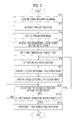
- Fig. 2 is a flowchart illustrating the process performed in this embodiment.
- the projection image generation unit 11 acquires the three dimensional image V0 from the storage 2 (Step ST1) and projects the three dimensional image V0 from the point of view which is disposed at a predetermined position to generate a two-dimensional projection image P0 (Step ST2).
- the projection image generation unit 11 generates a volume rendering image as the projection image P0 using a known volume rendering method.
- the projection image P0 is not limited to the volume rendering image and may be a surface rendering image generated by a surface rendering method, an MIP image generated by an MIP method, and a MinIP image generated by a MinIP method.
- the generated projection image P0 is displayed on the display 3 (Step ST3).
- the operator operates the input device 4 to move, magnify, reduce, and rotate the displayed projection image P0, to display a desired structure in the three dimensional image V0 on the display 3, and to set a target point on the desired structure.
- the target point is set on the two-dimensional projection image P0. Therefore, in the following description, the target point is referred to as a two-dimensional target point.
- the apparatus 1 receives an instruction to set the two-dimensional target point (Step ST4).
- the two-dimensional target point is set as follows. The operator moves a pointer to the target point on the projection image P0 displayed on the display 3 and uses the input device 4 to input a target point setting instruction.
- the three dimensional target point setting unit 12 sets, as the three dimensional target point, a target point on the three dimensional image V0 which corresponds to the two-dimensional target point set to the projection image P0 (Step ST5).
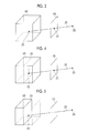
- Fig. 3 is a diagram illustrating the setting of the three dimensional target point. As shown in Fig. 3 , the three dimensional target point setting unit 12 sets, as a three dimensional target point 23, an intersection point of a three dimensional structure included in the three dimensional image V0 and a projection line 22 which extends from a point of view 20 when the projection image P0 is generated to a two-dimensional target point 21 set to the projection image P0.
- the three dimensional target point setting unit 12 integrates the opacity of pixels on the projection line 22 in the three dimensional image V0 from the point of view 20 and sets a pixel, which has an integrated value greater than a predetermined threshold value Th1, on the projection line 22 as the three dimensional target point 23.
- the three dimensional target point 23 is a point, which intersects the projection line 22 first, on the three dimensional structure in the three dimensional image V0.
- the projection image P0 is an MIP image
- the three dimensional target point 23 is a point with the maximum signal value on the projection line 22.
- the projection image P0 is a MinIP image
- the three dimensional target point 23 is a point with the minimum signal value on the projection line 22.
- the three dimensional target point setting unit 12 may set the three dimensional target point 23 in the structure, to which the two-dimensional target point 21 is set, in the three dimensional image V0. Specifically, the three dimensional target point setting unit 12 may set, as the three dimensional target point 23, a point that is disposed on the side opposite to the point of view 20 and is a predetermined distance away from the intersection point of the projection line 22 and the three dimensional structure.
- the radius of the tubular structure is assumed and a point that is disposed on the side opposite to the point of view 20 and is a distance corresponding to the radius of the tubular structure from the intersection point may be set as the three dimensional target point 23. Then, the three dimensional target point 23 is located in the tubular structure to which the two-dimensional target point 21 is set.
- the radius of the tubular structure may be a value which is set for each structure in advance or a value which is calculated by analyzing the projection image P0. In addition, the radius may be a value which is manually determined by the operator.
- the reference cross-section setting unit 13 sets a reference cross-section based on the three dimensional target point 23 to the three dimensional image V0 (Step ST6).
- Fig. 4 is a diagram illustrating the reference cross-section.
- the reference cross-section setting unit 13 sets, as an initial reference cross-section 25, a cross-section which includes the three dimensional target point 23 and is perpendicular to the projection line 22 passing through the three dimensional target point 23 from the point of view 20 at which the projection image P0 has been generated.
- the cross-sectional image generation unit 14 generates a projection image in which an object that is closer to the point of view 20 than to the reference cross-section 25 in the three dimensional image V0 is not displayed (Step ST7).
- the projection image is referred to as a cross-sectional projection image P1 since it is a projection image of the reference cross-section 25.
- Fig. 5 is a diagram illustrating the generation of the cross-sectional projection image.
- the cross-sectional image generation unit 14 does not display the object that is closer to the point of view 20 than to the reference cross-section 25 in the three dimensional image V0.
- the non-displayed state is represented by a dashed line.
- the three dimensional image V0 in which the object closer to the point of view 20 than to the reference cross-section 25 is not displayed is projected from the point of view 20 to generate the cross-sectional projection image P1.
- the cross-sectional projection image P1 is generated such that the three dimensional target point 23 of the reference cross-section 25 is located at the center of the cross-sectional projection image P1.
- the center of the cross-sectional projection image P1 is an intersection point of the diagonal lines of the cross-sectional projection image P1.
- the position of the projection surface may be the same as or different from that of the projection image P0.
- the cross-sectional projection image P1 of only the object in a specific range 27 which has the three dimensional target point 23 of the reference cross-section 25 as its center in the three dimensional image V0 may be generated.
- only a projection image 28 corresponding to the object in the specific range 27 is included in the cross-sectional projection image P1.
- the cross-sectional projection image P1 is displayed on the display 3 (Step ST8).
- a cross-sectional image of the reference cross-section 25 may be used, instead of the cross-sectional projection image P1.
- the cross-sectional image of the reference cross-section 25 may be combined with the projection image of the three dimensional image V0 in which the object closer to the point of view 20 than to the reference cross-section 25 is not displayed to generate the cross-sectional projection image P1.
- Fig. 7 is a diagram illustrating the cross-sectional projection images before and after the cross-sectional image of the reference cross-section 25 is combined. As shown in Fig. 7 , in the projection image before the image combination, it is possible to view the heart and the blood vessels on the surface of the heart.
- the operator operates the input device 4 to change the position of the point of view such that the observation direction of the structure, to which the three dimensional target point 23 is set, is aligned with a target direction, that is, a target three dimensional direction in the cross-sectional projection image P1. Therefore, the direction determination unit 15 determines whether an instruction to change the position of the point of view is input by the operator (Step ST9).
- the target three dimensional direction means a direction in a three dimensional space which is considered by the operator to be suitable for the observation of the structure, to which the three dimensional target point 23 is set, in the three dimensional image V0.
- the three dimensional target point 23 is set to a tubular structure, such as the blood vessel or the trachea
- the extension direction of the tubular structure included in the cross-sectional projection image P1 is aligned with a direction perpendicular to the currently displayed cross-sectional projection image P1, that is, a direction perpendicular to the display surface of the display 3 and is suitable for observation
- the target three dimensional direction is perpendicular to the reference cross-section 25 from which the cross-sectional projection image P1 has been generated.
- the target three dimensional direction is parallel to the reference cross-section 25 from which the cross-sectional projection image P1 has been generated.
- the direction perpendicular to the reference cross-section 25 is referred to as the target three dimensional direction.
- Step ST9 When the determination result in Step ST9 is "Yes", the direction determination unit 15 instructs the reference cross-section setting unit 13 and the cross-sectional image generation unit 14 to change the position of the point of view and to repeatedly perform the process from Step ST6 to Step ST8. Then, the reference cross-section setting unit 13 sets, as a new reference cross-section 25, a cross-section which is perpendicular to a new projection line extending from the changed position of the point of view to the three dimensional target point 23. Therefore, the rotation of the reference cross-section 25 due to the change in the position of the point of view is made about the three dimensional target point 23.
- the operator may perform, for example, the operations of moving, magnifying, and reducing the cross-sectional projection image P1 in addition to the rotation.
- the cross-sectional image generation unit 14 generates a new cross-sectional projection image P1 of a new reference cross-section 25 in which an object that is closer to the point of view facing the new reference cross-section 25, that is, the changed point of view than to the new reference cross-section 25 is not displayed and displays the new cross-sectional projection image P1 on the display 3.
- Step ST9 No
- the direction determination unit 15 determines whether the direction determination instruction is input (Step ST10). When the determination result in Step ST10 is "No", the process returns to Step ST9.
- Step ST10 determines a three dimensional direction for observing the three dimensional image V0 (Step ST11) and the process ends.
- the three dimensional direction for observing the three dimensional image V0 is a direction in a three dimensional space which extends from the current position of the point of view to the three dimensional target point 23.
- Fig. 8 is a diagram illustrating the projection image which is displayed first in the process according to this embodiment.
- the operator sets the two-dimensional target point 21 to the projection image P0 displayed on the display 3.
- Fig. 8 shows a state in which the two-dimensional target point 21 is set to a blood vessel 30 which is viewed in the projection image P0.
- the operator changes the position of the point of view of the cross-sectional projection image P1 in the cross-sectional projection image P1 displayed on the display 3 such that the extension direction of the blood vessel 30 is perpendicular to the display 3.
- a projection image P3 a slice image of the reference cross-section 25 is combined with the projection image P3. Therefore, the slice image of the reference cross-section 25 is combined at a position corresponding to the three dimensional target point 23.
- the position of the point of view is changed such that the blood vessel 30 is perpendicular to the display 3.
- an image showing the cross-section of the blood vessel 30 is included in the slice image of the reference cross-section 25. Therefore, a slice image 32 of the blood vessel 30 can be viewed at the position of the three dimensional target point 23 in the projection image shown in Fig. 9 .
- the object which is closer to the changed point of view than to the reference cross-section 25 in the three dimensional image V0 is not displayed. Therefore, as shown in Fig. 10 , the object 31 which is viewed in the projection image P3 shown in Fig. 9 is not included in the cross-sectional projection image P1 and the blood vessel 30 to which the three dimensional target point 23 is set can be viewed. In Fig. 10 , since the slice image of the reference cross-section 25 is combined with the cross-sectional projection image P1, the slice image 32 of the blood vessel 30 can be viewed at the position of the three dimensional target point 23.
- the position of the point of view of the displayed cross-sectional projection image P1 is changed to change the direction of the structure to which the three dimensional target point 23 is set. Therefore, it is possible to set the three dimensional direction in which the three dimensional image V0 is observed, using only the two-dimensional image obtained from the three dimensional image V0.
- the object which is closer to the point of view facing a reference point than to the reference cross-section 25 included in the three dimensional image V0 is not displayed. Therefore, it is possible to check the structure included in the cross-sectional projection image P1 without being disrupted by the structure close to the point of view. As a result, it is possible to accurately set the three dimensional direction in which the three dimensional image V0 is observed.
- a coincidence calculation unit 16 may be provided which calculates the coincidence between the pixel value (CT value) of the three dimensional target point 23 in the three dimensional image V0 and a pixel value on a line extending from the three dimensional target point 23 in the target three dimensional direction and the coincidence calculated by the coincidence calculation unit 16 may be displayed on the cross-sectional projection image P1.
- Fig. 12 is a diagram illustrating the cross-sectional projection image P1 on which the coincidence is displayed. As shown in Fig. 12 , an arrow 35 indicating the target three dimensional direction is displayed on the cross-sectional projection image P1. The length of the arrow 35 is changed according to the coincidence.
- the length of the arrow 35 is reduced.
- the length of the arrow 35 is increased by a value indicated by a dashed line.
- the concentration or color of the arrow may be changed according to the coincidence or a value indicating the coincidence may be displayed.
- the average values of a plurality of pixel values on a line which extends from the three dimensional target point 23 in the target three dimensional direction may be used as the pixel value on the line which extends from the three dimensional target point 23 in the target three dimensional direction.
- the ratio of a pixel value A1 of the three dimensional target point 23 to the average value A2 of a plurality of pixel values on the line extending from the three dimensional target point 23 in the target three dimensional direction or the absolute value of the difference between the pixel value A1 and the average value A2 can be used as the coincidence.
- the coincidence is the ratio, the direction of the three dimensional image V0 which is being displayed becomes closer to the target three dimensional direction as the coincidence becomes closer to 1.
- the coincidence is the absolute value of the difference
- the direction of the three dimensional image V0 which is being displayed becomes closer to the target three dimensional direction as the coincidence becomes closer to 0.
- the operator can easily recognize the degree of coincidence between the extension direction of the structure to which the three dimensional target point is set and the target three dimensional direction. Therefore, it is possible to effectively perform an operation of determining the three dimensional direction of the three dimensional image V0.
- the reference cross-section setting unit 13 sets, as the reference cross-section 25, the cross-section which includes the three dimensional target point 23 and is perpendicular to the projection line 22 extending from the point of view 20 to the three dimensional target point 23.
- three dimensional principal component analysis may be performed in a region in the vicinity of the three dimensional target point 23 in the three dimensional image V0 to estimate the direction in which the structure having the three dimensional target point 23 set thereto is present, for example, the extension direction of the structure in this embodiment and a cross-section which includes the three dimensional target point 23 and is perpendicular to the estimated direction may be set as the reference cross-section 25.
- a method which calculates the eigenvalues of a 3 ⁇ 3 Hessian matrix for each local area of the structure having the three dimensional target point 23 set thereto is used as the principal component analysis method.
- one of the three eigenvalues of the Hessian matrix is close to 0 and the remaining two values are relatively large values.
- an eigenvector which corresponds to the eigenvalue close to 0 indicates the direction of the main axis of the linear structure.
- the direction of the eigenvector is the direction in which the structure having the three dimensional target point 23 set thereto is present.
- Fig. 13 is a diagram illustrating the setting of the cross-section perpendicular to the direction which is estimated by the principal component analysis to the reference cross-section.
- the reference cross-section setting unit 13 sets, as the reference cross-section 25, a cross-section which includes the three dimensional target point 23 and is perpendicular to the arrow 36. In this case, as shown in Fig.
- a point of view 20A for generating the cross-sectional projection image P1 is located on a line which passes through the three dimensional target point 23 and is perpendicular to the reference cross-section 25 that is set by the principal component analysis.
- Fig. 13 also shows the projection line 22 from the initial projection start point 20.
- the structure to which the three dimensional target point 23 is set is oriented in the target three dimensional direction or a direction close to the three dimensional direction in the cross-sectional projection image P1. Therefore, it is possible to effectively perform an operation of aligning the observation direction of the structure to which the three dimensional target point 23 is set with the target three dimensional direction.
- the direction perpendicular to the reference cross-section 25 is the target three dimensional direction.
- a direction parallel to the reference cross-section 25 may be the target three dimensional direction.
- the cross-sectional projection image P1 including a blood vessel 37 which extends in parallel to a screen is displayed on the display 3, as shown in Fig. 14 .
- the blood vessel 37 extends in parallel to a display surface of the display 3, but the direction of the blood vessel 37 on the display surface is not determined. Therefore, it is preferable to operate the input device 4 to two-dimensionally rotate the cross-sectional projection image P1 about the three dimensional target point 23.
- the blood vessel 37 to which the three dimensional target point 23 is set can be oriented in the target three dimensional direction (here, the direction horizontal to the display screen). Therefore, it is possible to align the observation direction of the blood vessel 37 with the target three dimensional direction.
- two-dimensional principal component analysis may be performed in an area in the vicinity of the three dimensional target point 23, using the cross-sectional image of the reference cross-section 25, to estimate the direction in which the structure having the three dimensional target point 23 set thereto is present in the reference cross-section 25 and the estimated direction may be used as the target three dimensional direction.
- two-dimensional principal component analysis is performed in an area in the vicinity of the three dimensional target point 23.
- the cross-sectional projection image P1 is displayed on the display 3.
- a projection image of a cross-section which is perpendicular to the reference cross-section 25 including the three dimensional target point 23 may be generated and displayed together with the cross-sectional projection image P1.
- the two-dimensional target point (three dimensional target point) is set to the tubular structure, such as a blood vessel or the trachea.
- the operator may set the target point to any desired structure.
- the position of the point of view 20 is changed to rotate the reference cross-section 25.
- the point of view 20 may be fixed and the three dimensional image V0 may be rotated to rotate the reference cross-section 25.
Landscapes
- Engineering & Computer Science (AREA)
- Theoretical Computer Science (AREA)
- Physics & Mathematics (AREA)
- General Physics & Mathematics (AREA)
- Software Systems (AREA)
- Computer Graphics (AREA)
- Computer Hardware Design (AREA)
- General Engineering & Computer Science (AREA)
- Radar, Positioning & Navigation (AREA)
- Remote Sensing (AREA)
- Computing Systems (AREA)
- Geometry (AREA)
- Architecture (AREA)
- Apparatus For Radiation Diagnosis (AREA)
- Image Processing (AREA)
- Image Generation (AREA)
- Image Analysis (AREA)
- Magnetic Resonance Imaging Apparatus (AREA)
Applications Claiming Priority (1)
| Application Number | Priority Date | Filing Date | Title |
|---|---|---|---|
| JP2014067655A JP6040193B2 (ja) | 2014-03-28 | 2014-03-28 | 3次元方向設定装置および方法並びにプログラム |
Publications (2)
| Publication Number | Publication Date |
|---|---|
| EP2930695A1 true EP2930695A1 (de) | 2015-10-14 |
| EP2930695B1 EP2930695B1 (de) | 2019-09-04 |
Family
ID=52814808
Family Applications (1)
| Application Number | Title | Priority Date | Filing Date |
|---|---|---|---|
| EP15159669.9A Active EP2930695B1 (de) | 2014-03-28 | 2015-03-18 | Dreidimensionale Orientierungskonfigurationsvorrichtung, Verfahren und Programm |
Country Status (3)
| Country | Link |
|---|---|
| US (1) | US9589391B2 (de) |
| EP (1) | EP2930695B1 (de) |
| JP (1) | JP6040193B2 (de) |
Families Citing this family (9)
| Publication number | Priority date | Publication date | Assignee | Title |
|---|---|---|---|---|
| JP6040193B2 (ja) * | 2014-03-28 | 2016-12-07 | 富士フイルム株式会社 | 3次元方向設定装置および方法並びにプログラム |
| KR102551239B1 (ko) | 2015-09-02 | 2023-07-05 | 인터디지털 씨이 페이튼트 홀딩스, 에스에이에스 | 확장된 장면에서의 내비게이션을 용이하게 하기 위한 방법, 장치 및 시스템 |
| JP6745633B2 (ja) * | 2016-04-13 | 2020-08-26 | キヤノン株式会社 | 画像処理装置、画像処理方法、及びプログラム |
| EP3509033B1 (de) | 2016-08-30 | 2024-02-28 | Canon Kabushiki Kaisha | Bildverarbeitungsvorrichtung, bildverarbeitungsverfahren, bildverarbeitungsprogramm und bildverarbeitungssystem |
| WO2019065466A1 (ja) * | 2017-09-29 | 2019-04-04 | キヤノン株式会社 | 画像処理装置、画像処理方法、およびプログラム |
| JP7133828B2 (ja) * | 2017-10-17 | 2022-09-09 | 国立大学法人千葉大学 | 内視鏡画像処理プログラム及び内視鏡システム |
| US10922897B2 (en) * | 2018-01-15 | 2021-02-16 | Canon Medical Systems Corporation | Medical information processing apparatus, X-ray diagnostic system, and medical information processing method |
| JP7038576B2 (ja) * | 2018-03-09 | 2022-03-18 | 東芝Itコントロールシステム株式会社 | Ct撮影装置 |
| CN111275803B (zh) * | 2020-02-25 | 2023-06-02 | 北京百度网讯科技有限公司 | 3d模型渲染方法、装置、设备和存储介质 |
Citations (3)
| Publication number | Priority date | Publication date | Assignee | Title |
|---|---|---|---|---|
| JP2005322257A (ja) | 2005-05-25 | 2005-11-17 | Hitachi Medical Corp | 3次元画像処理方法 |
| EP1981000A2 (de) * | 2007-04-12 | 2008-10-15 | FUJIFILM Corporation | Bildanzeigeverfahren, Vorrichtung und Programm |
| JP2009022476A (ja) | 2007-07-18 | 2009-02-05 | Ziosoft Inc | 画像表示装置、画像表示装置の制御方法、および画像表示装置の制御プログラム |
Family Cites Families (17)
| Publication number | Priority date | Publication date | Assignee | Title |
|---|---|---|---|---|
| US5734384A (en) * | 1991-11-29 | 1998-03-31 | Picker International, Inc. | Cross-referenced sectioning and reprojection of diagnostic image volumes |
| JP3327948B2 (ja) * | 1992-06-09 | 2002-09-24 | オリンパス光学工業株式会社 | 光学像再構成装置 |
| JP3483929B2 (ja) * | 1994-04-05 | 2004-01-06 | 株式会社日立製作所 | 3次元画像生成方法 |
| JP3570576B2 (ja) * | 1995-06-19 | 2004-09-29 | 株式会社日立製作所 | マルチモダリティに対応した3次元画像合成表示装置 |
| JP3527796B2 (ja) * | 1995-06-29 | 2004-05-17 | 株式会社日立製作所 | 高速3次元画像生成装置および方法 |
| IT1297396B1 (it) * | 1997-12-30 | 1999-09-01 | Francesco Buzzigoli | Metodo e dispositivo per la ricostruzione di immagini tridimensionali di vasi sanguigni, in particolare di arterie coronarie, o di altre |
| JP4443672B2 (ja) * | 1998-10-14 | 2010-03-31 | 株式会社東芝 | 超音波診断装置 |
| AU2003232983A1 (en) * | 2002-06-05 | 2003-12-22 | Koninklijke Philips Electronics N.V. | Analysis of a multi-dimensional structure |
| US7355605B2 (en) * | 2003-09-22 | 2008-04-08 | Siemens Medical Solutions Usa, Inc. | Method and system for automatic orientation of local visualization techniques for vessel structures |
| JP4407434B2 (ja) * | 2004-08-31 | 2010-02-03 | 株式会社セガ | 画像処理装置、画像処理方法及び画像処理プログラム |
| US7463262B2 (en) * | 2004-09-30 | 2008-12-09 | Kabushiki Kaisha Toshiba | Image processing apparatus and method |
| US7991211B2 (en) * | 2007-01-22 | 2011-08-02 | Siemens Aktiengesellschaft | Method and system for guided two dimensional colon screening |
| US7573039B2 (en) * | 2007-03-13 | 2009-08-11 | Smith Bruce D | Compton camera configuration and imaging method |
| JP2009018115A (ja) * | 2007-07-13 | 2009-01-29 | Toshiba Corp | 3次元超音波診断装置 |
| US20130182079A1 (en) * | 2012-01-17 | 2013-07-18 | Ocuspec | Motion capture using cross-sections of an object |
| US9123147B2 (en) * | 2012-09-07 | 2015-09-01 | Carestream Health, Inc. | Imaging apparatus for display of maxillary and mandibular arches |
| JP6040193B2 (ja) * | 2014-03-28 | 2016-12-07 | 富士フイルム株式会社 | 3次元方向設定装置および方法並びにプログラム |
-
2014
- 2014-03-28 JP JP2014067655A patent/JP6040193B2/ja not_active Expired - Fee Related
-
2015
- 2015-03-18 EP EP15159669.9A patent/EP2930695B1/de active Active
- 2015-03-23 US US14/665,037 patent/US9589391B2/en not_active Expired - Fee Related
Patent Citations (3)
| Publication number | Priority date | Publication date | Assignee | Title |
|---|---|---|---|---|
| JP2005322257A (ja) | 2005-05-25 | 2005-11-17 | Hitachi Medical Corp | 3次元画像処理方法 |
| EP1981000A2 (de) * | 2007-04-12 | 2008-10-15 | FUJIFILM Corporation | Bildanzeigeverfahren, Vorrichtung und Programm |
| JP2009022476A (ja) | 2007-07-18 | 2009-02-05 | Ziosoft Inc | 画像表示装置、画像表示装置の制御方法、および画像表示装置の制御プログラム |
Non-Patent Citations (2)
| Title |
|---|
| HAN SUK KIM, DIDEM UNAT, SCOTT B. BADEN, JÜRGEN P. SCHULZE: "Interactive Data-Centric Viewpoint Selection", SPIE, PROCEEDINGS OF CONFERENCE ON VISUALIZATION AND DATA ANALYSIS, vol. 8294, 2012, pages 829405-1 - 829405-12, XP002743690, Retrieved from the Internet <URL:http://proceedings.spiedigitallibrary.org/proceeding.aspx?articleid=1283754> [retrieved on 20150827] * |
| YUAN, F.: "Real time multiple planar volume clipping based on the programmable graphics process unit", OPTICA APPLICATA, vol. XXXIX, no. 2, 2009, pages 331 - 345, XP002743689, Retrieved from the Internet <URL:http://citeseerx.ist.psu.edu/viewdoc/download?rep=rep1&type=pdf&doi=10.1.1.215.2301> [retrieved on 20150827] * |
Also Published As
| Publication number | Publication date |
|---|---|
| JP2015188574A (ja) | 2015-11-02 |
| EP2930695B1 (de) | 2019-09-04 |
| JP6040193B2 (ja) | 2016-12-07 |
| US9589391B2 (en) | 2017-03-07 |
| US20150279120A1 (en) | 2015-10-01 |
Similar Documents
| Publication | Publication Date | Title |
|---|---|---|
| EP2930695B1 (de) | Dreidimensionale Orientierungskonfigurationsvorrichtung, Verfahren und Programm | |
| US12361608B2 (en) | Enhancements for displaying and viewing tomosynthesis images | |
| US20190355174A1 (en) | Information processing apparatus, information processing system, information processing method, and computer-readable recording medium | |
| US10417517B2 (en) | Medical image correlation apparatus, method and storage medium | |
| US9179893B2 (en) | Image processing apparatus, image processing method, image processing system, and program | |
| US7796835B2 (en) | Computer readable medium for image processing and image processing method | |
| CN111656402B (zh) | 用于与血管图像交互的设备、系统和方法 | |
| CN107169919B (zh) | 用于3d医学体积的加速读取的方法和系统 | |
| EP3136338B1 (de) | Informationsverarbeitungs-vorrichtung, informationsverarbeitungs-verfahren und programm | |
| CN104586418B (zh) | 医用图像数据处理装置和医用图像数据处理方法 | |
| JP6480922B2 (ja) | ボリュメトリック画像データの視覚化 | |
| CN113658284B (zh) | 用于训练结节检测系统的来自ct图像的x射线图像合成 | |
| US20170360396A1 (en) | Ultrasound imaging apparatus and method for segmenting anatomical objects | |
| JP6430500B2 (ja) | 腫瘍の奏効測定を支援するための方法 | |
| CN113506277A (zh) | 图像处理方法及装置 | |
| JP2017225835A (ja) | 画像処理装置 | |
| JP5701208B2 (ja) | 医用画像表示装置及び医用画像表示方法 | |
| JP6487999B2 (ja) | 情報処理装置、情報処理方法、及びプログラム | |
| JP6768415B2 (ja) | 画像処理装置、画像処理方法およびプログラム | |
| JP2017023834A (ja) | 画像処理装置、撮影システム及び画像処理方法 | |
| JP6391544B2 (ja) | 医用画像処理装置、医用画像処理方法、及びプログラム | |
| EP4258207A1 (de) | Automatische rippenbruchdetektion aus ungefalteten abtastbildern |
Legal Events
| Date | Code | Title | Description |
|---|---|---|---|
| PUAI | Public reference made under article 153(3) epc to a published international application that has entered the european phase |
Free format text: ORIGINAL CODE: 0009012 |
|
| AK | Designated contracting states |
Kind code of ref document: A1 Designated state(s): AL AT BE BG CH CY CZ DE DK EE ES FI FR GB GR HR HU IE IS IT LI LT LU LV MC MK MT NL NO PL PT RO RS SE SI SK SM TR |
|
| AX | Request for extension of the european patent |
Extension state: BA ME |
|
| 17P | Request for examination filed |
Effective date: 20160322 |
|
| RBV | Designated contracting states (corrected) |
Designated state(s): AL AT BE BG CH CY CZ DE DK EE ES FI FR GB GR HR HU IE IS IT LI LT LU LV MC MK MT NL NO PL PT RO RS SE SI SK SM TR |
|
| STAA | Information on the status of an ep patent application or granted ep patent |
Free format text: STATUS: EXAMINATION IS IN PROGRESS |
|
| 17Q | First examination report despatched |
Effective date: 20171123 |
|
| GRAP | Despatch of communication of intention to grant a patent |
Free format text: ORIGINAL CODE: EPIDOSNIGR1 |
|
| STAA | Information on the status of an ep patent application or granted ep patent |
Free format text: STATUS: GRANT OF PATENT IS INTENDED |
|
| INTG | Intention to grant announced |
Effective date: 20190327 |
|
| GRAS | Grant fee paid |
Free format text: ORIGINAL CODE: EPIDOSNIGR3 |
|
| GRAA | (expected) grant |
Free format text: ORIGINAL CODE: 0009210 |
|
| STAA | Information on the status of an ep patent application or granted ep patent |
Free format text: STATUS: THE PATENT HAS BEEN GRANTED |
|
| AK | Designated contracting states |
Kind code of ref document: B1 Designated state(s): AL AT BE BG CH CY CZ DE DK EE ES FI FR GB GR HR HU IE IS IT LI LT LU LV MC MK MT NL NO PL PT RO RS SE SI SK SM TR |
|
| REG | Reference to a national code |
Ref country code: GB Ref legal event code: FG4D |
|
| REG | Reference to a national code |
Ref country code: CH Ref legal event code: EP |
|
| REG | Reference to a national code |
Ref country code: AT Ref legal event code: REF Ref document number: 1176457 Country of ref document: AT Kind code of ref document: T Effective date: 20190915 |
|
| REG | Reference to a national code |
Ref country code: DE Ref legal event code: R096 Ref document number: 602015037020 Country of ref document: DE |
|
| REG | Reference to a national code |
Ref country code: IE Ref legal event code: FG4D |
|
| REG | Reference to a national code |
Ref country code: NL Ref legal event code: MP Effective date: 20190904 |
|
| REG | Reference to a national code |
Ref country code: LT Ref legal event code: MG4D |
|
| PG25 | Lapsed in a contracting state [announced via postgrant information from national office to epo] |
Ref country code: BG Free format text: LAPSE BECAUSE OF FAILURE TO SUBMIT A TRANSLATION OF THE DESCRIPTION OR TO PAY THE FEE WITHIN THE PRESCRIBED TIME-LIMIT Effective date: 20191204 Ref country code: SE Free format text: LAPSE BECAUSE OF FAILURE TO SUBMIT A TRANSLATION OF THE DESCRIPTION OR TO PAY THE FEE WITHIN THE PRESCRIBED TIME-LIMIT Effective date: 20190904 Ref country code: NO Free format text: LAPSE BECAUSE OF FAILURE TO SUBMIT A TRANSLATION OF THE DESCRIPTION OR TO PAY THE FEE WITHIN THE PRESCRIBED TIME-LIMIT Effective date: 20191204 Ref country code: HR Free format text: LAPSE BECAUSE OF FAILURE TO SUBMIT A TRANSLATION OF THE DESCRIPTION OR TO PAY THE FEE WITHIN THE PRESCRIBED TIME-LIMIT Effective date: 20190904 Ref country code: LT Free format text: LAPSE BECAUSE OF FAILURE TO SUBMIT A TRANSLATION OF THE DESCRIPTION OR TO PAY THE FEE WITHIN THE PRESCRIBED TIME-LIMIT Effective date: 20190904 Ref country code: FI Free format text: LAPSE BECAUSE OF FAILURE TO SUBMIT A TRANSLATION OF THE DESCRIPTION OR TO PAY THE FEE WITHIN THE PRESCRIBED TIME-LIMIT Effective date: 20190904 |
|
| PG25 | Lapsed in a contracting state [announced via postgrant information from national office to epo] |
Ref country code: GR Free format text: LAPSE BECAUSE OF FAILURE TO SUBMIT A TRANSLATION OF THE DESCRIPTION OR TO PAY THE FEE WITHIN THE PRESCRIBED TIME-LIMIT Effective date: 20191205 Ref country code: ES Free format text: LAPSE BECAUSE OF FAILURE TO SUBMIT A TRANSLATION OF THE DESCRIPTION OR TO PAY THE FEE WITHIN THE PRESCRIBED TIME-LIMIT Effective date: 20190904 Ref country code: RS Free format text: LAPSE BECAUSE OF FAILURE TO SUBMIT A TRANSLATION OF THE DESCRIPTION OR TO PAY THE FEE WITHIN THE PRESCRIBED TIME-LIMIT Effective date: 20190904 Ref country code: AL Free format text: LAPSE BECAUSE OF FAILURE TO SUBMIT A TRANSLATION OF THE DESCRIPTION OR TO PAY THE FEE WITHIN THE PRESCRIBED TIME-LIMIT Effective date: 20190904 Ref country code: LV Free format text: LAPSE BECAUSE OF FAILURE TO SUBMIT A TRANSLATION OF THE DESCRIPTION OR TO PAY THE FEE WITHIN THE PRESCRIBED TIME-LIMIT Effective date: 20190904 |
|
| REG | Reference to a national code |
Ref country code: AT Ref legal event code: MK05 Ref document number: 1176457 Country of ref document: AT Kind code of ref document: T Effective date: 20190904 |
|
| PG25 | Lapsed in a contracting state [announced via postgrant information from national office to epo] |
Ref country code: PT Free format text: LAPSE BECAUSE OF FAILURE TO SUBMIT A TRANSLATION OF THE DESCRIPTION OR TO PAY THE FEE WITHIN THE PRESCRIBED TIME-LIMIT Effective date: 20200106 Ref country code: NL Free format text: LAPSE BECAUSE OF FAILURE TO SUBMIT A TRANSLATION OF THE DESCRIPTION OR TO PAY THE FEE WITHIN THE PRESCRIBED TIME-LIMIT Effective date: 20190904 Ref country code: IT Free format text: LAPSE BECAUSE OF FAILURE TO SUBMIT A TRANSLATION OF THE DESCRIPTION OR TO PAY THE FEE WITHIN THE PRESCRIBED TIME-LIMIT Effective date: 20190904 Ref country code: RO Free format text: LAPSE BECAUSE OF FAILURE TO SUBMIT A TRANSLATION OF THE DESCRIPTION OR TO PAY THE FEE WITHIN THE PRESCRIBED TIME-LIMIT Effective date: 20190904 Ref country code: EE Free format text: LAPSE BECAUSE OF FAILURE TO SUBMIT A TRANSLATION OF THE DESCRIPTION OR TO PAY THE FEE WITHIN THE PRESCRIBED TIME-LIMIT Effective date: 20190904 Ref country code: AT Free format text: LAPSE BECAUSE OF FAILURE TO SUBMIT A TRANSLATION OF THE DESCRIPTION OR TO PAY THE FEE WITHIN THE PRESCRIBED TIME-LIMIT Effective date: 20190904 Ref country code: PL Free format text: LAPSE BECAUSE OF FAILURE TO SUBMIT A TRANSLATION OF THE DESCRIPTION OR TO PAY THE FEE WITHIN THE PRESCRIBED TIME-LIMIT Effective date: 20190904 |
|
| PGFP | Annual fee paid to national office [announced via postgrant information from national office to epo] |
Ref country code: DE Payment date: 20200303 Year of fee payment: 6 |
|
| PG25 | Lapsed in a contracting state [announced via postgrant information from national office to epo] |
Ref country code: IS Free format text: LAPSE BECAUSE OF FAILURE TO SUBMIT A TRANSLATION OF THE DESCRIPTION OR TO PAY THE FEE WITHIN THE PRESCRIBED TIME-LIMIT Effective date: 20200224 Ref country code: SK Free format text: LAPSE BECAUSE OF FAILURE TO SUBMIT A TRANSLATION OF THE DESCRIPTION OR TO PAY THE FEE WITHIN THE PRESCRIBED TIME-LIMIT Effective date: 20190904 Ref country code: SM Free format text: LAPSE BECAUSE OF FAILURE TO SUBMIT A TRANSLATION OF THE DESCRIPTION OR TO PAY THE FEE WITHIN THE PRESCRIBED TIME-LIMIT Effective date: 20190904 Ref country code: CZ Free format text: LAPSE BECAUSE OF FAILURE TO SUBMIT A TRANSLATION OF THE DESCRIPTION OR TO PAY THE FEE WITHIN THE PRESCRIBED TIME-LIMIT Effective date: 20190904 |
|
| REG | Reference to a national code |
Ref country code: DE Ref legal event code: R097 Ref document number: 602015037020 Country of ref document: DE |
|
| PLBE | No opposition filed within time limit |
Free format text: ORIGINAL CODE: 0009261 |
|
| STAA | Information on the status of an ep patent application or granted ep patent |
Free format text: STATUS: NO OPPOSITION FILED WITHIN TIME LIMIT |
|
| PG2D | Information on lapse in contracting state deleted |
Ref country code: IS |
|
| PG25 | Lapsed in a contracting state [announced via postgrant information from national office to epo] |
Ref country code: DK Free format text: LAPSE BECAUSE OF FAILURE TO SUBMIT A TRANSLATION OF THE DESCRIPTION OR TO PAY THE FEE WITHIN THE PRESCRIBED TIME-LIMIT Effective date: 20190904 Ref country code: IS Free format text: LAPSE BECAUSE OF FAILURE TO SUBMIT A TRANSLATION OF THE DESCRIPTION OR TO PAY THE FEE WITHIN THE PRESCRIBED TIME-LIMIT Effective date: 20200105 |
|
| 26N | No opposition filed |
Effective date: 20200605 |
|
| PG25 | Lapsed in a contracting state [announced via postgrant information from national office to epo] |
Ref country code: SI Free format text: LAPSE BECAUSE OF FAILURE TO SUBMIT A TRANSLATION OF THE DESCRIPTION OR TO PAY THE FEE WITHIN THE PRESCRIBED TIME-LIMIT Effective date: 20190904 |
|
| PG25 | Lapsed in a contracting state [announced via postgrant information from national office to epo] |
Ref country code: MC Free format text: LAPSE BECAUSE OF FAILURE TO SUBMIT A TRANSLATION OF THE DESCRIPTION OR TO PAY THE FEE WITHIN THE PRESCRIBED TIME-LIMIT Effective date: 20190904 |
|
| REG | Reference to a national code |
Ref country code: CH Ref legal event code: PL |
|
| REG | Reference to a national code |
Ref country code: BE Ref legal event code: MM Effective date: 20200331 |
|
| PG25 | Lapsed in a contracting state [announced via postgrant information from national office to epo] |
Ref country code: LU Free format text: LAPSE BECAUSE OF NON-PAYMENT OF DUE FEES Effective date: 20200318 |
|
| PG25 | Lapsed in a contracting state [announced via postgrant information from national office to epo] |
Ref country code: CH Free format text: LAPSE BECAUSE OF NON-PAYMENT OF DUE FEES Effective date: 20200331 Ref country code: IE Free format text: LAPSE BECAUSE OF NON-PAYMENT OF DUE FEES Effective date: 20200318 Ref country code: LI Free format text: LAPSE BECAUSE OF NON-PAYMENT OF DUE FEES Effective date: 20200331 |
|
| PG25 | Lapsed in a contracting state [announced via postgrant information from national office to epo] |
Ref country code: BE Free format text: LAPSE BECAUSE OF NON-PAYMENT OF DUE FEES Effective date: 20200331 |
|
| GBPC | Gb: european patent ceased through non-payment of renewal fee |
Effective date: 20200318 |
|
| PG25 | Lapsed in a contracting state [announced via postgrant information from national office to epo] |
Ref country code: GB Free format text: LAPSE BECAUSE OF NON-PAYMENT OF DUE FEES Effective date: 20200318 |
|
| REG | Reference to a national code |
Ref country code: DE Ref legal event code: R119 Ref document number: 602015037020 Country of ref document: DE |
|
| PG25 | Lapsed in a contracting state [announced via postgrant information from national office to epo] |
Ref country code: DE Free format text: LAPSE BECAUSE OF NON-PAYMENT OF DUE FEES Effective date: 20211001 |
|
| PG25 | Lapsed in a contracting state [announced via postgrant information from national office to epo] |
Ref country code: TR Free format text: LAPSE BECAUSE OF FAILURE TO SUBMIT A TRANSLATION OF THE DESCRIPTION OR TO PAY THE FEE WITHIN THE PRESCRIBED TIME-LIMIT Effective date: 20190904 Ref country code: MT Free format text: LAPSE BECAUSE OF FAILURE TO SUBMIT A TRANSLATION OF THE DESCRIPTION OR TO PAY THE FEE WITHIN THE PRESCRIBED TIME-LIMIT Effective date: 20190904 Ref country code: CY Free format text: LAPSE BECAUSE OF FAILURE TO SUBMIT A TRANSLATION OF THE DESCRIPTION OR TO PAY THE FEE WITHIN THE PRESCRIBED TIME-LIMIT Effective date: 20190904 |
|
| PG25 | Lapsed in a contracting state [announced via postgrant information from national office to epo] |
Ref country code: MK Free format text: LAPSE BECAUSE OF FAILURE TO SUBMIT A TRANSLATION OF THE DESCRIPTION OR TO PAY THE FEE WITHIN THE PRESCRIBED TIME-LIMIT Effective date: 20190904 |
|
| PG25 | Lapsed in a contracting state [announced via postgrant information from national office to epo] |
Ref country code: FR Free format text: LAPSE BECAUSE OF NON-PAYMENT OF DUE FEES Effective date: 20200331 |