EP2930723A2 - Procédé et dispositif destinés au traitement d'un fil - Google Patents
Procédé et dispositif destinés au traitement d'un fil Download PDFInfo
- Publication number
- EP2930723A2 EP2930723A2 EP15162545.6A EP15162545A EP2930723A2 EP 2930723 A2 EP2930723 A2 EP 2930723A2 EP 15162545 A EP15162545 A EP 15162545A EP 2930723 A2 EP2930723 A2 EP 2930723A2
- Authority
- EP
- European Patent Office
- Prior art keywords
- wire
- annealing furnace
- baking oven
- temperature
- coating
- Prior art date
- Legal status (The legal status is an assumption and is not a legal conclusion. Google has not performed a legal analysis and makes no representation as to the accuracy of the status listed.)
- Granted
Links
- 238000000034 method Methods 0.000 title claims abstract description 32
- 238000012545 processing Methods 0.000 title claims abstract description 5
- 238000000137 annealing Methods 0.000 claims abstract description 72
- 238000000576 coating method Methods 0.000 claims abstract description 38
- 239000011248 coating agent Substances 0.000 claims abstract description 35
- 229910052782 aluminium Inorganic materials 0.000 claims abstract description 18
- XAGFODPZIPBFFR-UHFFFAOYSA-N aluminium Chemical compound [Al] XAGFODPZIPBFFR-UHFFFAOYSA-N 0.000 claims abstract description 18
- 238000001953 recrystallisation Methods 0.000 claims abstract description 15
- 239000000463 material Substances 0.000 claims abstract description 12
- 238000010438 heat treatment Methods 0.000 claims description 11
- 238000001035 drying Methods 0.000 claims description 9
- 239000003973 paint Substances 0.000 description 17
- 229920003055 poly(ester-imide) Polymers 0.000 description 16
- RYGMFSIKBFXOCR-UHFFFAOYSA-N Copper Chemical compound [Cu] RYGMFSIKBFXOCR-UHFFFAOYSA-N 0.000 description 11
- 238000004140 cleaning Methods 0.000 description 9
- 229910052802 copper Inorganic materials 0.000 description 9
- 239000010949 copper Substances 0.000 description 9
- 239000002904 solvent Substances 0.000 description 6
- 239000003795 chemical substances by application Substances 0.000 description 5
- 238000004519 manufacturing process Methods 0.000 description 5
- 229910052751 metal Inorganic materials 0.000 description 5
- 239000002184 metal Substances 0.000 description 5
- 229920002312 polyamide-imide Polymers 0.000 description 5
- 239000002987 primer (paints) Substances 0.000 description 5
- 239000004962 Polyamide-imide Substances 0.000 description 4
- 238000005265 energy consumption Methods 0.000 description 4
- 239000007789 gas Substances 0.000 description 3
- 239000004922 lacquer Substances 0.000 description 3
- 239000007788 liquid Substances 0.000 description 3
- 230000003647 oxidation Effects 0.000 description 3
- 238000007254 oxidation reaction Methods 0.000 description 3
- 238000007591 painting process Methods 0.000 description 3
- 229920000642 polymer Polymers 0.000 description 3
- IJGRMHOSHXDMSA-UHFFFAOYSA-N Atomic nitrogen Chemical compound N#N IJGRMHOSHXDMSA-UHFFFAOYSA-N 0.000 description 2
- 238000005299 abrasion Methods 0.000 description 2
- 239000000853 adhesive Substances 0.000 description 2
- 230000001070 adhesive effect Effects 0.000 description 2
- 238000001816 cooling Methods 0.000 description 2
- 239000011261 inert gas Substances 0.000 description 2
- 238000010422 painting Methods 0.000 description 2
- 239000004033 plastic Substances 0.000 description 2
- 229920003023 plastic Polymers 0.000 description 2
- 230000005855 radiation Effects 0.000 description 2
- 241000196324 Embryophyta Species 0.000 description 1
- 241001289460 Muehlenbeckia complexa Species 0.000 description 1
- 238000002679 ablation Methods 0.000 description 1
- 238000004026 adhesive bonding Methods 0.000 description 1
- 239000012298 atmosphere Substances 0.000 description 1
- 230000009286 beneficial effect Effects 0.000 description 1
- 230000015572 biosynthetic process Effects 0.000 description 1
- 238000006243 chemical reaction Methods 0.000 description 1
- 239000008199 coating composition Substances 0.000 description 1
- 210000003298 dental enamel Anatomy 0.000 description 1
- 230000001419 dependent effect Effects 0.000 description 1
- 230000001627 detrimental effect Effects 0.000 description 1
- 238000010586 diagram Methods 0.000 description 1
- 238000004534 enameling Methods 0.000 description 1
- 238000005516 engineering process Methods 0.000 description 1
- 238000010304 firing Methods 0.000 description 1
- 238000000227 grinding Methods 0.000 description 1
- 238000009413 insulation Methods 0.000 description 1
- 238000002844 melting Methods 0.000 description 1
- 230000008018 melting Effects 0.000 description 1
- 229910052757 nitrogen Inorganic materials 0.000 description 1
- 238000002161 passivation Methods 0.000 description 1
- 238000012805 post-processing Methods 0.000 description 1
- 238000002360 preparation method Methods 0.000 description 1
- 238000011165 process development Methods 0.000 description 1
- 230000001681 protective effect Effects 0.000 description 1
- 229920003002 synthetic resin Polymers 0.000 description 1
- 239000000057 synthetic resin Substances 0.000 description 1
- 239000002966 varnish Substances 0.000 description 1
- XLYOFNOQVPJJNP-UHFFFAOYSA-N water Chemical compound O XLYOFNOQVPJJNP-UHFFFAOYSA-N 0.000 description 1
- 238000004804 winding Methods 0.000 description 1
- 238000005491 wire drawing Methods 0.000 description 1
Images



Classifications
-
- H—ELECTRICITY
- H01—ELECTRIC ELEMENTS
- H01B—CABLES; CONDUCTORS; INSULATORS; SELECTION OF MATERIALS FOR THEIR CONDUCTIVE, INSULATING OR DIELECTRIC PROPERTIES
- H01B13/00—Apparatus or processes specially adapted for manufacturing conductors or cables
- H01B13/06—Insulating conductors or cables
- H01B13/065—Insulating conductors with lacquers or enamels
-
- F—MECHANICAL ENGINEERING; LIGHTING; HEATING; WEAPONS; BLASTING
- F27—FURNACES; KILNS; OVENS; RETORTS
- F27B—FURNACES, KILNS, OVENS OR RETORTS IN GENERAL; OPEN SINTERING OR LIKE APPARATUS
- F27B3/00—Hearth-type furnaces, e.g. of reverberatory type; Electric arc furnaces ; Tank furnaces
- F27B3/10—Details, accessories or equipment, e.g. dust-collectors, specially adapted for hearth-type furnaces
- F27B3/28—Arrangement of controlling, monitoring, alarm or the like devices
-
- F—MECHANICAL ENGINEERING; LIGHTING; HEATING; WEAPONS; BLASTING
- F27—FURNACES; KILNS; OVENS; RETORTS
- F27B—FURNACES, KILNS, OVENS OR RETORTS IN GENERAL; OPEN SINTERING OR LIKE APPARATUS
- F27B9/00—Furnaces through which the charge is moved mechanically, e.g. of tunnel type; Similar furnaces in which the charge moves by gravity
- F27B9/06—Furnaces through which the charge is moved mechanically, e.g. of tunnel type; Similar furnaces in which the charge moves by gravity heated without contact between combustion gases and charge; electrically heated
- F27B9/10—Furnaces through which the charge is moved mechanically, e.g. of tunnel type; Similar furnaces in which the charge moves by gravity heated without contact between combustion gases and charge; electrically heated heated by hot air or gas
Definitions
- the invention relates to a method and a device for processing a wire, in particular an aluminum wire, wherein in a coating device for applying at least one layer of a coating on the wire at least one layer of a coating material is applied to the wire and the applied layer then in a baking oven for Drying or curing of the applied layer is dried or hardened, wherein the wire before the application of the layer and recrystallization of the wire through a separate from the baking oven annealing furnace, which is arranged in the wire conveying direction in front of the baking oven and is arranged for recrystallization of the wire promoted becomes.
- the invention relates both to the preparation of a previously drawn wire on a coating and the application of the coating, wherein the wire is an uncoated bare wire, the metal structure is distorted due to the plastic deformation of the wire during the drawing, so that it has a corresponding reduced extensibility or Has tensile strength.
- one or more coating materials may be applied to the wire in multiple layers and / or as a coating composition. Suitable coating materials are any lacquers or synthetic resins which are conventionally used in the coating or enameling of wires, in particular polyester imide (PEI) and / or polyamide imide (PAI).
- the baking oven (often referred to as a coating oven, kiln, or "curing oven”) is designed to dry and cure the coating.
- In-line annealing of copper wires in thermally heated tube annealing which uses inert gases such as water vapor (or nitrogen), is currently taking place in enamel wire systems. are flowed through.
- the heat input into the wire takes place in such tube annealing convective on the proper movement of the wire through the inert gas atmosphere, heat radiation between Glührohrinnenwand and wire, and finally via heat conduction between Glührohrinnenwand and standing in direct contact with this wire (grinding wire).
- the heat input through heat conduction is dominant.
- the contact between the wire and the tube wall is even required in this case to provide the necessary heat transfer rates at the high throughput speeds.
- this describes CN 102074308 A a device and a process for producing painted aluminum wires, wherein the annealing of the unpainted wires and the curing after the application of the paint is carried out in one and the same furnace.
- the problem here is that for physical and thermodynamic reasons, however, these processes require different wire temperatures to complete them. Since both the soft-to-glow wire traces (ie, the tracks or sections of the wire in the oven) and the wire tracks to be coated forcibly have the same residence time in the oven at the same furnace conditions, but now form almost the same temperature profiles along the individual wire tracks.
- the JP H05-325684 A shows a painting process for copper wires with an annealing furnace, wherein the still soft wire is painted after annealing and used for curing of the wire itself heat energy emitted.
- the CN 103000313 A shows a vertical painting machine in which a wire is conveyed from a unwinding by a glow, a paint container and a separate baking oven.
- the CN 103258600 A relates to a painting process for aluminum wires, wherein the wires are annealed in a three-layer process with different temperatures. Subsequently, a primer layer and a lacquer layer is applied directly to the wire and cured in a baking oven.
- JP S59-28530 A a manufacturing process for painted copper or aluminum wires, wherein the drawn wire is continuously passed through an inline annealing system and annealed at a constant coating speed. After the annealing furnace, the wire is coated with varnish, which is then cured in its own baking oven.
- the method should also largely avoid detrimental to the process safety heating of solvent vapors and at the same time reduce the energy consumption associated with the process or the device.
- the invention provides that in the annealing furnace, a substantially self-contained flow of a hot gas, in particular a circulating air flow, is generated, which flow is preferably directed counter to the wire conveying direction.
- the annealing furnace is preferably for heating the wire by means of a heated in a substantially closed circuit heated gas, in particular by means of hot air, is set up.
- the annealing furnace (or simply called annealer) is preferably designed for non-contact heating of the wire, so that even a wire made of a material with a relatively low softening temperature is not damaged in the annealing furnace.
- the annealing furnace is provided separately from the stoving means in this context means that the annealing furnace is spatially and thermally separated from the stoving furnace and has an independent heat supply, in particular an independent heating element or an independent heat generating unit.
- the arrangement of the annealing furnace in the wire conveying direction before the baking oven is of course independent of the geometric arrangement of the two ovens and merely means that in the course of producing a coated wire, a portion of the wire to be processed first passes the annealing furnace, ie is conveyed through the annealing furnace, before the same section passes the baking oven.
- the annealing furnace is adjusted in terms of the temperature generated in the annealing furnace or the temperature profile to which the wire is exposed, so that an optimal recrystallization of the metal structure of the wire is achieved.
- the recrystallization takes place, as is known, above a temperature dependent on the wire material, which can be suitably selected by the person skilled in the art, and the annealing furnace can be adjusted accordingly.
- the wire is preferably coated after the last exit from the annealing furnace and before the first entry into the stoving furnace.
- the separate ovens Another advantage of the separate ovens is that thereby a high wire entry temperature in the Annealing furnace is made possible because no solvent vapors are to be feared, and the wire does not need to be cooled after drawing. Due to the closed flow or the circulating air, the annealing furnace has a particularly low process air discharge as well as a lower fresh air supply required compared with a furnace which is set up for drying a wire coating. The otherwise necessary heating of the fresh air supplied can therefore be omitted, at least for the most part, which reduces the energy consumption associated with the method or device.
- the annealing furnace allows a separate annealing process of the wire with higher transport rates than in the subsequent baking oven. The higher transport rates in the annealing furnace are achieved by a higher temperature level and, in particular in the case of a flow directed counter to the direction of the wire feed, by better convective heat transfer by means of suitable flow guidance.
- the annealing furnace is controllable independently of the baking oven for setting different temperature profiles and corresponding wire temperatures.
- the energy consumption associated with the generation of the respective temperature profile can be optimized in this case to the respective task of the furnace.
- the wire is heated in the baking oven to a relatively lower wire temperature than in the annealing furnace. Accordingly, during operation, the average temperature in the annealing furnace is advantageously higher than the average temperature in the stoving furnace. Due to the temperature difference between baking oven and annealing furnace different wire temperatures can be achieved in the two ovens even at the same wire speed, ie with the same amount of wire carried out. Due to the lower temperature in the baking oven, temperature losses during the coating of the wire can be reduced and thus the energy consumption can be further reduced overall.
- the lower temperatures in the baking oven are also advantageous in terms of process reliability, since thus excessive heating of the solvent vapors produced during drying is avoided. Due to the higher wire temperature in the annealing furnace, which may be above a suitable or permissible for the drying of a coating temperature, a much better recrystallization and thus better softness and extensibility (higher elongation at break) of the wire can be achieved.
- the wire temperature for example, in the annealing furnace above 360 ° C, in particular between 380 and 480 ° C, and / or in the baking oven below 360 ° C, in particular between 280 and 320 ° C.
- the wire is conveyed through the annealing furnace at least twice, preferably between four and fifteen times, in particular approximately ten times, a significantly improved cleaning of the wire can be achieved in addition to the recrystallization. Due to the multiple implementation by the correspondingly hot annealing furnace, for example, drawing agent residues are burned in layers of the wire. In this way, a suitable cleaning of the wire can be achieved even at wire temperatures below 450 ° C, so that a higher energy efficiency compared to a cleaning in one step at temperatures above 450 ° C is achieved.
- the coating material can be applied directly to the wire, ie the coating material intended for insulating the wire is applied directly to the metallic surface of the wire.
- a primer or comparable adhesive bonding layers can be dispensed with, so that the finished wire advantageously has a comparatively higher temperature resistance of the coating and higher thermal class.
- the wire between the two ovens i. between the annealing furnace and the baking oven
- a Nachspannvorraum in particular via a pneumatic dancer
- the post-tensioning device can compensate for voltage differences due to wire temperature differences and improves the smooth and trouble-free conveyance of the wire from the annealing furnace and into the stoving furnace.
- Wire drawing distorts the metal texture of the wire due to plastic deformation. It increases its strength and hardness, while the extensibility deteriorates massively.
- the wire In order to fulfill the mechanical-technological requirements relevant to the post-processing of the wire, the wire must again become “soft", which requires a reshaping of the microstructure. For this purpose, the wire must be heated accordingly.
- Fig. 1 The graph shown is plotted on the abscissa, the wire temperature T and on the ordinate the achieved "softness" or extensibility R of the wire.
- the drawn curve R (T) schematically represents the relationship between the wire temperature T and the extensibility R.
- the indicated temperatures T1, T2, T3 show approximately the optimum temperature T1 for the hardening of a wire coating, the optimum temperature T2 for recrystallization of the wire (corresponding to the formation of a homogeneous microstructure and thus the maximum achievable extensibility R) and the optimum temperature T3 for cleaning off drawing agent residues from the freshly drawn wire.
- the temperature T1 would be approximately between 280 ° and 320 ° C, the temperature T2 between 380 and 400 ° C and the temperature T3 between 450 and 480 ° C.
- Fig. 2 a production line for producing a coated wire is shown, wherein the wire is pulled in drawing machines 1, then conveyed through the annealing furnace 2 several times.
- the thin wire usually passes to the drawing machine 1 via pulleys in an electrically heated tube annealing, which allows the heating of the copper wire via thermal radiation, but above all by direct wall contact via heat conduction.
- An annealing process with direct wall contact can not be used, for example, with aluminum wires, since compared to copper much lower softening temperatures are present and the wire would therefore be massively damaged.
- Such wires ie wires with relatively low softening temperatures, can be heated for annealing, for example with hot moving air; This method is non-contact and the occurring, for example, in the case of Aludrähten oxidation in contrast to copper wires is not a problem because it is self-passivating.
- the wire is heated accordingly in the annealing furnace 2 with hot moving air (see. Fig. 4 ).
- the heat-treated wire is fed via deflection rollers of the coating device 3, for example in the form of a lacquerware, at the Einbrennofeneintritt where the liquid paint is applied to the wire at ambient temperature.
- the dissolved polymers in the paints subsequently crosslink chemically after application and characterize the actual curing process of the paint.
- the paint is applied via conically shaped wiping nozzles, which are continuously fed by means of a pump pump with fresh paint. There, a paint film with a preset thickness is evenly applied to the wire surface. Due to limited adhesion of the liquid paint on the wire, the application of the paint required for the desired insulating layer thickness must be done in several steps. For this purpose, the enameled wire is guided in up to 24 tracks via two grooved deflecting rollers between the lacquerware at the oven inlet and the radiator end through the stoving oven 4.
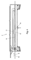
- Fig. 4 schematically shows a longitudinal section parallel to the wire conveying direction 9 through the annealing furnace 2. On an inlet side 10 of the uncooled bare wire is introduced into the annealing furnace 2.
- a high wire inlet temperature enables a small temperature loss or a small necessary heat input and an optimal recrystallization of the wire 14.
- the flow of the hot circulating air in the annealing furnace 2 along a closed circuit is indicated by the arrows 11, 12.
- the hot air in the wire transport region 13 flows counter to the wire conveying direction 9 (cf. Fig. 5 ) to allow optimum heat convection and thus maximum heat transfer from the hot air to the wire. Due to the high temperature of the hot air, residues 15 on the bare wire, eg drawing agent residues, can be removed or burned off in layers.
- the successive removal of the residues 15 from the wire 14 is in Fig. 6 shown schematically, wherein the three wire cross sections 16 each show a different progress of the ablation.
- the uppermost wire cross section 17 shows the wire 14 before the first pass through the annealing furnace 2, wherein all remaining after pulling on the wire 14 residues 15 are still present;
- the mean wire cross section 18 shows the wire after five passes, whereby already the majority of the residues 15 could be removed;
- the lowermost wire section 19 shows the completely cleaned wire 14 after the tenth pass through the annealing furnace 2.
Landscapes
- Engineering & Computer Science (AREA)
- Mechanical Engineering (AREA)
- General Engineering & Computer Science (AREA)
- Manufacturing & Machinery (AREA)
- Chemical & Material Sciences (AREA)
- Combustion & Propulsion (AREA)
- Application Of Or Painting With Fluid Materials (AREA)
Applications Claiming Priority (1)
| Application Number | Priority Date | Filing Date | Title |
|---|---|---|---|
| ATA50263/2014A AT515617B1 (de) | 2014-04-07 | 2014-04-07 | Verfahren und Vorrichtung zur Verarbeitung eines Drahtes |
Publications (3)
| Publication Number | Publication Date |
|---|---|
| EP2930723A2 true EP2930723A2 (fr) | 2015-10-14 |
| EP2930723A3 EP2930723A3 (fr) | 2015-11-11 |
| EP2930723B1 EP2930723B1 (fr) | 2018-12-12 |
Family
ID=53008273
Family Applications (1)
| Application Number | Title | Priority Date | Filing Date |
|---|---|---|---|
| EP15162545.6A Not-in-force EP2930723B1 (fr) | 2014-04-07 | 2015-04-07 | Procédé et dispositif destinés au traitement d'un fil |
Country Status (3)
| Country | Link |
|---|---|
| EP (1) | EP2930723B1 (fr) |
| AT (1) | AT515617B1 (fr) |
| ES (1) | ES2719980T3 (fr) |
Cited By (1)
| Publication number | Priority date | Publication date | Assignee | Title |
|---|---|---|---|---|
| CN109637748A (zh) * | 2018-12-06 | 2019-04-16 | 广东新中南电缆有限公司 | 一种电缆铜线制备工艺 |
Families Citing this family (4)
| Publication number | Priority date | Publication date | Assignee | Title |
|---|---|---|---|---|
| CN112366038B (zh) * | 2020-11-02 | 2022-03-18 | 浙江涌金线材股份有限公司 | 一种漆包线加工工艺 |
| EP4635635A1 (fr) | 2024-04-18 | 2025-10-22 | MAG machines GmbH | Dispositif de revêtement pour appliquer un matériau de revêtement sur un fil, et dispositif et procédé de fabrication de fils revêtus |
| EP4659871A1 (fr) | 2024-06-06 | 2025-12-10 | MAG machines GmbH | Procédé et dispositif de fabrication de fils revêtus avec un dispositif racleur pour enlever le matériau de revêtement excédentaire d'un fil revêtu |
| EP4699707A1 (fr) | 2024-08-20 | 2026-02-25 | MAG machines GmbH | Dispositif de revêtement pour appliquer au moins une couche d'un matériau de revêtement sur un fil |
Citations (5)
| Publication number | Priority date | Publication date | Assignee | Title |
|---|---|---|---|---|
| JPS5928530A (ja) | 1982-08-09 | 1984-02-15 | Fujikura Ltd | エナメル線の製造方法 |
| JPH05325684A (ja) | 1992-05-21 | 1993-12-10 | Hitachi Cable Ltd | エナメル線の製造方法 |
| CN102074308A (zh) | 2010-11-16 | 2011-05-25 | 诸暨露笑特种线有限公司 | 一种铝漆包线的生产系统及其工艺 |
| CN103000313A (zh) | 2011-09-14 | 2013-03-27 | 吴江市神州机械有限公司 | 小型立式漆包机 |
| CN103258600A (zh) | 2012-02-16 | 2013-08-21 | 宜春德源欣茂铝业有限公司 | 电机180级聚酯亚胺漆包铝圆线的包漆方法 |
Family Cites Families (6)
| Publication number | Priority date | Publication date | Assignee | Title |
|---|---|---|---|---|
| NL136430C (fr) * | 1963-09-25 | |||
| US4521173A (en) * | 1981-04-29 | 1985-06-04 | Phelps Dodge Magnet Wire Co. | Apparatus for manufacturing magnet wire |
| DE3118830C2 (de) * | 1981-05-12 | 1983-05-11 | MAG Maschinen und Apparatebau GmbH, 8055 Graz | "Anlage zur Lackdrahtherstellung im Inlineverfahren" |
| DE4010306C2 (de) * | 1990-03-30 | 1999-06-10 | Mag Masch App | Verfahren und Vorrichtung zur Herstellung von Lackdrähten mit Schmelzharzen |
| JPH0928530A (ja) * | 1995-07-18 | 1997-02-04 | Dainippon Printing Co Ltd | ホログラムを用いた情報表示展示装置 |
| CN1212260C (zh) * | 2001-05-24 | 2005-07-27 | 中国科学院电工研究所 | 高温超导电缆绕制机 |
-
2014
- 2014-04-07 AT ATA50263/2014A patent/AT515617B1/de not_active IP Right Cessation
-
2015
- 2015-04-07 EP EP15162545.6A patent/EP2930723B1/fr not_active Not-in-force
- 2015-04-07 ES ES15162545T patent/ES2719980T3/es active Active
Patent Citations (5)
| Publication number | Priority date | Publication date | Assignee | Title |
|---|---|---|---|---|
| JPS5928530A (ja) | 1982-08-09 | 1984-02-15 | Fujikura Ltd | エナメル線の製造方法 |
| JPH05325684A (ja) | 1992-05-21 | 1993-12-10 | Hitachi Cable Ltd | エナメル線の製造方法 |
| CN102074308A (zh) | 2010-11-16 | 2011-05-25 | 诸暨露笑特种线有限公司 | 一种铝漆包线的生产系统及其工艺 |
| CN103000313A (zh) | 2011-09-14 | 2013-03-27 | 吴江市神州机械有限公司 | 小型立式漆包机 |
| CN103258600A (zh) | 2012-02-16 | 2013-08-21 | 宜春德源欣茂铝业有限公司 | 电机180级聚酯亚胺漆包铝圆线的包漆方法 |
Cited By (1)
| Publication number | Priority date | Publication date | Assignee | Title |
|---|---|---|---|---|
| CN109637748A (zh) * | 2018-12-06 | 2019-04-16 | 广东新中南电缆有限公司 | 一种电缆铜线制备工艺 |
Also Published As
| Publication number | Publication date |
|---|---|
| AT515617B1 (de) | 2016-04-15 |
| EP2930723A3 (fr) | 2015-11-11 |
| ES2719980T3 (es) | 2019-07-17 |
| EP2930723B1 (fr) | 2018-12-12 |
| AT515617A1 (de) | 2015-10-15 |
Similar Documents
| Publication | Publication Date | Title |
|---|---|---|
| EP2930723B1 (fr) | Procédé et dispositif destinés au traitement d'un fil | |
| EP3010646A1 (fr) | Procédé de revêtement d'une surface d'un substrat électriquement non conducteur au moyen de peintures en poudre | |
| EP2236217B1 (fr) | Procédé et dispositif de revêtement de tuyaux métalliques ou d'autres composants longs ayant une section transversale limitée | |
| DE69708482T2 (de) | Durchlaufglühverfahren von Metallband in verschiedenen Schutzgasen und Vorrichtung | |
| WO2013000001A1 (fr) | Procédé de réchauffement d'un élément façonné pour une trempe à la presse effectuée par la suite et four continu destiné au réchauffement par endroits d'un élément façonné préchauffé à une température prédéfinie à une température plus élevée | |
| CH664529A5 (de) | Verfahren zum ummanteln von stabfoermigen metallischen formkoerpern mit thermoplastischem kunststoff. | |
| AT509596B1 (de) | Verfahren zum erwärmen eines formbauteils für ein anschliessendes presshärten sowie durchlaufofen zum bereichsweisen erwärmen eines auf eine vorgegebene temperatur vorgewärmten formbauteils auf eine höhere temperatur | |
| WO2013020977A1 (fr) | Dispositif de revêtement de fils électroconducteurs | |
| EP2531624B1 (fr) | Dispositif et procédé de traitement thermique de fils d'acier | |
| EP0023238B1 (fr) | Procédé et dispositif de fabrication de fils à bobiner isolés par un vernis, en particulier fils épais | |
| DE69621333T2 (de) | In-line beschichten und härten von kontinuierlich bewegten geschweissten rohren mit organischen polymeren | |
| WO2009074344A1 (fr) | Dispositif de refroidissement et procédé de refroidissement d'objets sortant d'un dispositif d'application de revêtement | |
| DE2843895A1 (de) | Verfahren und vorrichtung zur herstellung von mit ultraviolett-strahlung haertbarem lack isolierten elektrischen leiterdraehten, insbesondere profilierten starkdraehten | |
| DE4010306C2 (de) | Verfahren und Vorrichtung zur Herstellung von Lackdrähten mit Schmelzharzen | |
| DE1652395B2 (de) | Verfahren und Einrichtung zum kontinuierlichen Emaillackieren von Draht | |
| EP2466237B1 (fr) | Installation de séchage à infrarouges | |
| WO2004031671A1 (fr) | Procede et dispositif de traitement thermique d'une piece | |
| DE10106890B4 (de) | Verfahren und Anordnung zur Herstellung eines quasi-endlosen beschichteten, wickelfähigen Bleches | |
| DE1554943A1 (de) | Verfahren und Einrichtung zum Verbinden von synthetischem Harz mit Metall | |
| AT318037B (de) | Fertigungsanlage zur Isolierung von Drähten od.dgl. mit hochprozentigen Lacken | |
| EP0157737A1 (fr) | Procédé pour fabriquer un produit composite metal/matière plastique | |
| EP1384523A1 (fr) | Procédé d'application en lit fluidisé et en continu d'un revêtement sans chromate sur un tube | |
| WO2013135416A1 (fr) | Dispositif de revêtement par pulvérisation et procédé de revêtement par pulvérisation | |
| DE102015001438A1 (de) | Flexible Wärmebehandlungsanlage für metalisches Band | |
| JPS621468A (ja) | 異形鉄筋の塗装方法および装置 |
Legal Events
| Date | Code | Title | Description |
|---|---|---|---|
| PUAL | Search report despatched |
Free format text: ORIGINAL CODE: 0009013 |
|
| PUAI | Public reference made under article 153(3) epc to a published international application that has entered the european phase |
Free format text: ORIGINAL CODE: 0009012 |
|
| AK | Designated contracting states |
Kind code of ref document: A2 Designated state(s): AL AT BE BG CH CY CZ DE DK EE ES FI FR GB GR HR HU IE IS IT LI LT LU LV MC MK MT NL NO PL PT RO RS SE SI SK SM TR |
|
| AX | Request for extension of the european patent |
Extension state: BA ME |
|
| AK | Designated contracting states |
Kind code of ref document: A3 Designated state(s): AL AT BE BG CH CY CZ DE DK EE ES FI FR GB GR HR HU IE IS IT LI LT LU LV MC MK MT NL NO PL PT RO RS SE SI SK SM TR |
|
| AX | Request for extension of the european patent |
Extension state: BA ME |
|
| RIC1 | Information provided on ipc code assigned before grant |
Ipc: H01B 13/06 20060101AFI20151006BHEP |
|
| 17P | Request for examination filed |
Effective date: 20160511 |
|
| RBV | Designated contracting states (corrected) |
Designated state(s): AL AT BE BG CH CY CZ DE DK EE ES FI FR GB GR HR HU IE IS IT LI LT LU LV MC MK MT NL NO PL PT RO RS SE SI SK SM TR |
|
| STAA | Information on the status of an ep patent application or granted ep patent |
Free format text: STATUS: EXAMINATION IS IN PROGRESS |
|
| 17Q | First examination report despatched |
Effective date: 20170714 |
|
| REG | Reference to a national code |
Ref country code: DE Ref legal event code: R079 Ref document number: 502015007165 Country of ref document: DE Free format text: PREVIOUS MAIN CLASS: H01B0013060000 Ipc: F27B0009100000 |
|
| RIC1 | Information provided on ipc code assigned before grant |
Ipc: F27B 9/10 20060101AFI20180420BHEP |
|
| GRAP | Despatch of communication of intention to grant a patent |
Free format text: ORIGINAL CODE: EPIDOSNIGR1 |
|
| STAA | Information on the status of an ep patent application or granted ep patent |
Free format text: STATUS: GRANT OF PATENT IS INTENDED |
|
| INTG | Intention to grant announced |
Effective date: 20180601 |
|
| GRAS | Grant fee paid |
Free format text: ORIGINAL CODE: EPIDOSNIGR3 |
|
| GRAA | (expected) grant |
Free format text: ORIGINAL CODE: 0009210 |
|
| STAA | Information on the status of an ep patent application or granted ep patent |
Free format text: STATUS: THE PATENT HAS BEEN GRANTED |
|
| AK | Designated contracting states |
Kind code of ref document: B1 Designated state(s): AL AT BE BG CH CY CZ DE DK EE ES FI FR GB GR HR HU IE IS IT LI LT LU LV MC MK MT NL NO PL PT RO RS SE SI SK SM TR |
|
| REG | Reference to a national code |
Ref country code: GB Ref legal event code: FG4D Free format text: NOT ENGLISH |
|
| REG | Reference to a national code |
Ref country code: CH Ref legal event code: EP |
|
| REG | Reference to a national code |
Ref country code: AT Ref legal event code: REF Ref document number: 1076574 Country of ref document: AT Kind code of ref document: T Effective date: 20181215 |
|
| REG | Reference to a national code |
Ref country code: DE Ref legal event code: R096 Ref document number: 502015007165 Country of ref document: DE |
|
| REG | Reference to a national code |
Ref country code: IE Ref legal event code: FG4D Free format text: LANGUAGE OF EP DOCUMENT: GERMAN |
|
| REG | Reference to a national code |
Ref country code: NL Ref legal event code: MP Effective date: 20181212 |
|
| REG | Reference to a national code |
Ref country code: LT Ref legal event code: MG4D |
|
| PG25 | Lapsed in a contracting state [announced via postgrant information from national office to epo] |
Ref country code: BG Free format text: LAPSE BECAUSE OF FAILURE TO SUBMIT A TRANSLATION OF THE DESCRIPTION OR TO PAY THE FEE WITHIN THE PRESCRIBED TIME-LIMIT Effective date: 20190312 Ref country code: HR Free format text: LAPSE BECAUSE OF FAILURE TO SUBMIT A TRANSLATION OF THE DESCRIPTION OR TO PAY THE FEE WITHIN THE PRESCRIBED TIME-LIMIT Effective date: 20181212 Ref country code: LT Free format text: LAPSE BECAUSE OF FAILURE TO SUBMIT A TRANSLATION OF THE DESCRIPTION OR TO PAY THE FEE WITHIN THE PRESCRIBED TIME-LIMIT Effective date: 20181212 Ref country code: NO Free format text: LAPSE BECAUSE OF FAILURE TO SUBMIT A TRANSLATION OF THE DESCRIPTION OR TO PAY THE FEE WITHIN THE PRESCRIBED TIME-LIMIT Effective date: 20190312 Ref country code: LV Free format text: LAPSE BECAUSE OF FAILURE TO SUBMIT A TRANSLATION OF THE DESCRIPTION OR TO PAY THE FEE WITHIN THE PRESCRIBED TIME-LIMIT Effective date: 20181212 Ref country code: FI Free format text: LAPSE BECAUSE OF FAILURE TO SUBMIT A TRANSLATION OF THE DESCRIPTION OR TO PAY THE FEE WITHIN THE PRESCRIBED TIME-LIMIT Effective date: 20181212 |
|
| PG25 | Lapsed in a contracting state [announced via postgrant information from national office to epo] |
Ref country code: AL Free format text: LAPSE BECAUSE OF FAILURE TO SUBMIT A TRANSLATION OF THE DESCRIPTION OR TO PAY THE FEE WITHIN THE PRESCRIBED TIME-LIMIT Effective date: 20181212 Ref country code: SE Free format text: LAPSE BECAUSE OF FAILURE TO SUBMIT A TRANSLATION OF THE DESCRIPTION OR TO PAY THE FEE WITHIN THE PRESCRIBED TIME-LIMIT Effective date: 20181212 Ref country code: RS Free format text: LAPSE BECAUSE OF FAILURE TO SUBMIT A TRANSLATION OF THE DESCRIPTION OR TO PAY THE FEE WITHIN THE PRESCRIBED TIME-LIMIT Effective date: 20181212 Ref country code: GR Free format text: LAPSE BECAUSE OF FAILURE TO SUBMIT A TRANSLATION OF THE DESCRIPTION OR TO PAY THE FEE WITHIN THE PRESCRIBED TIME-LIMIT Effective date: 20190313 |
|
| PG25 | Lapsed in a contracting state [announced via postgrant information from national office to epo] |
Ref country code: NL Free format text: LAPSE BECAUSE OF FAILURE TO SUBMIT A TRANSLATION OF THE DESCRIPTION OR TO PAY THE FEE WITHIN THE PRESCRIBED TIME-LIMIT Effective date: 20181212 |
|
| REG | Reference to a national code |
Ref country code: ES Ref legal event code: FG2A Ref document number: 2719980 Country of ref document: ES Kind code of ref document: T3 Effective date: 20190717 |
|
| PG25 | Lapsed in a contracting state [announced via postgrant information from national office to epo] |
Ref country code: CZ Free format text: LAPSE BECAUSE OF FAILURE TO SUBMIT A TRANSLATION OF THE DESCRIPTION OR TO PAY THE FEE WITHIN THE PRESCRIBED TIME-LIMIT Effective date: 20181212 Ref country code: PT Free format text: LAPSE BECAUSE OF FAILURE TO SUBMIT A TRANSLATION OF THE DESCRIPTION OR TO PAY THE FEE WITHIN THE PRESCRIBED TIME-LIMIT Effective date: 20190412 Ref country code: PL Free format text: LAPSE BECAUSE OF FAILURE TO SUBMIT A TRANSLATION OF THE DESCRIPTION OR TO PAY THE FEE WITHIN THE PRESCRIBED TIME-LIMIT Effective date: 20181212 |
|
| PG25 | Lapsed in a contracting state [announced via postgrant information from national office to epo] |
Ref country code: EE Free format text: LAPSE BECAUSE OF FAILURE TO SUBMIT A TRANSLATION OF THE DESCRIPTION OR TO PAY THE FEE WITHIN THE PRESCRIBED TIME-LIMIT Effective date: 20181212 Ref country code: IS Free format text: LAPSE BECAUSE OF FAILURE TO SUBMIT A TRANSLATION OF THE DESCRIPTION OR TO PAY THE FEE WITHIN THE PRESCRIBED TIME-LIMIT Effective date: 20190412 Ref country code: SK Free format text: LAPSE BECAUSE OF FAILURE TO SUBMIT A TRANSLATION OF THE DESCRIPTION OR TO PAY THE FEE WITHIN THE PRESCRIBED TIME-LIMIT Effective date: 20181212 Ref country code: RO Free format text: LAPSE BECAUSE OF FAILURE TO SUBMIT A TRANSLATION OF THE DESCRIPTION OR TO PAY THE FEE WITHIN THE PRESCRIBED TIME-LIMIT Effective date: 20181212 Ref country code: SM Free format text: LAPSE BECAUSE OF FAILURE TO SUBMIT A TRANSLATION OF THE DESCRIPTION OR TO PAY THE FEE WITHIN THE PRESCRIBED TIME-LIMIT Effective date: 20181212 |
|
| REG | Reference to a national code |
Ref country code: DE Ref legal event code: R097 Ref document number: 502015007165 Country of ref document: DE |
|
| PLBE | No opposition filed within time limit |
Free format text: ORIGINAL CODE: 0009261 |
|
| STAA | Information on the status of an ep patent application or granted ep patent |
Free format text: STATUS: NO OPPOSITION FILED WITHIN TIME LIMIT |
|
| PG25 | Lapsed in a contracting state [announced via postgrant information from national office to epo] |
Ref country code: SI Free format text: LAPSE BECAUSE OF FAILURE TO SUBMIT A TRANSLATION OF THE DESCRIPTION OR TO PAY THE FEE WITHIN THE PRESCRIBED TIME-LIMIT Effective date: 20181212 Ref country code: DK Free format text: LAPSE BECAUSE OF FAILURE TO SUBMIT A TRANSLATION OF THE DESCRIPTION OR TO PAY THE FEE WITHIN THE PRESCRIBED TIME-LIMIT Effective date: 20181212 |
|
| REG | Reference to a national code |
Ref country code: DE Ref legal event code: R119 Ref document number: 502015007165 Country of ref document: DE |
|
| 26N | No opposition filed |
Effective date: 20190913 |
|
| REG | Reference to a national code |
Ref country code: CH Ref legal event code: PL |
|
| REG | Reference to a national code |
Ref country code: BE Ref legal event code: MM Effective date: 20190430 |
|
| GBPC | Gb: european patent ceased through non-payment of renewal fee |
Effective date: 20190407 |
|
| PG25 | Lapsed in a contracting state [announced via postgrant information from national office to epo] |
Ref country code: LU Free format text: LAPSE BECAUSE OF NON-PAYMENT OF DUE FEES Effective date: 20190407 Ref country code: MC Free format text: LAPSE BECAUSE OF FAILURE TO SUBMIT A TRANSLATION OF THE DESCRIPTION OR TO PAY THE FEE WITHIN THE PRESCRIBED TIME-LIMIT Effective date: 20181212 |
|
| PG25 | Lapsed in a contracting state [announced via postgrant information from national office to epo] |
Ref country code: CH Free format text: LAPSE BECAUSE OF NON-PAYMENT OF DUE FEES Effective date: 20190430 Ref country code: LI Free format text: LAPSE BECAUSE OF NON-PAYMENT OF DUE FEES Effective date: 20190430 Ref country code: DE Free format text: LAPSE BECAUSE OF NON-PAYMENT OF DUE FEES Effective date: 20191101 Ref country code: GB Free format text: LAPSE BECAUSE OF NON-PAYMENT OF DUE FEES Effective date: 20190407 |
|
| PG25 | Lapsed in a contracting state [announced via postgrant information from national office to epo] |
Ref country code: FR Free format text: LAPSE BECAUSE OF NON-PAYMENT OF DUE FEES Effective date: 20190430 Ref country code: BE Free format text: LAPSE BECAUSE OF NON-PAYMENT OF DUE FEES Effective date: 20190430 |
|
| PG25 | Lapsed in a contracting state [announced via postgrant information from national office to epo] |
Ref country code: TR Free format text: LAPSE BECAUSE OF FAILURE TO SUBMIT A TRANSLATION OF THE DESCRIPTION OR TO PAY THE FEE WITHIN THE PRESCRIBED TIME-LIMIT Effective date: 20181212 |
|
| PG25 | Lapsed in a contracting state [announced via postgrant information from national office to epo] |
Ref country code: IE Free format text: LAPSE BECAUSE OF NON-PAYMENT OF DUE FEES Effective date: 20190407 Ref country code: IT Free format text: LAPSE BECAUSE OF NON-PAYMENT OF DUE FEES Effective date: 20190407 |
|
| REG | Reference to a national code |
Ref country code: ES Ref legal event code: FD2A Effective date: 20200828 |
|
| PG25 | Lapsed in a contracting state [announced via postgrant information from national office to epo] |
Ref country code: ES Free format text: LAPSE BECAUSE OF NON-PAYMENT OF DUE FEES Effective date: 20190408 |
|
| PG25 | Lapsed in a contracting state [announced via postgrant information from national office to epo] |
Ref country code: CY Free format text: LAPSE BECAUSE OF FAILURE TO SUBMIT A TRANSLATION OF THE DESCRIPTION OR TO PAY THE FEE WITHIN THE PRESCRIBED TIME-LIMIT Effective date: 20181212 |
|
| REG | Reference to a national code |
Ref country code: AT Ref legal event code: MM01 Ref document number: 1076574 Country of ref document: AT Kind code of ref document: T Effective date: 20200407 |
|
| PG25 | Lapsed in a contracting state [announced via postgrant information from national office to epo] |
Ref country code: HU Free format text: LAPSE BECAUSE OF FAILURE TO SUBMIT A TRANSLATION OF THE DESCRIPTION OR TO PAY THE FEE WITHIN THE PRESCRIBED TIME-LIMIT; INVALID AB INITIO Effective date: 20150407 Ref country code: MT Free format text: LAPSE BECAUSE OF FAILURE TO SUBMIT A TRANSLATION OF THE DESCRIPTION OR TO PAY THE FEE WITHIN THE PRESCRIBED TIME-LIMIT Effective date: 20181212 |
|
| PG25 | Lapsed in a contracting state [announced via postgrant information from national office to epo] |
Ref country code: AT Free format text: LAPSE BECAUSE OF NON-PAYMENT OF DUE FEES Effective date: 20200407 |
|
| PG25 | Lapsed in a contracting state [announced via postgrant information from national office to epo] |
Ref country code: MK Free format text: LAPSE BECAUSE OF FAILURE TO SUBMIT A TRANSLATION OF THE DESCRIPTION OR TO PAY THE FEE WITHIN THE PRESCRIBED TIME-LIMIT Effective date: 20181212 |