EP2930829A1 - C-förmige oder U-förmige Halbspule, Rotorwicklung mit einer derartigen Halbspule und dazugehöriges Herstellungsverfahren - Google Patents
C-förmige oder U-förmige Halbspule, Rotorwicklung mit einer derartigen Halbspule und dazugehöriges Herstellungsverfahren Download PDFInfo
- Publication number
- EP2930829A1 EP2930829A1 EP14164161.3A EP14164161A EP2930829A1 EP 2930829 A1 EP2930829 A1 EP 2930829A1 EP 14164161 A EP14164161 A EP 14164161A EP 2930829 A1 EP2930829 A1 EP 2930829A1
- Authority
- EP
- European Patent Office
- Prior art keywords
- coil
- conductor
- conductors
- winding
- turns
- Prior art date
- Legal status (The legal status is an assumption and is not a legal conclusion. Google has not performed a legal analysis and makes no representation as to the accuracy of the status listed.)
- Withdrawn
Links
Images





Classifications
-
- H—ELECTRICITY
- H02—GENERATION; CONVERSION OR DISTRIBUTION OF ELECTRIC POWER
- H02K—DYNAMO-ELECTRIC MACHINES
- H02K3/00—Details of windings
- H02K3/04—Windings characterised by the conductor shape, form or construction, e.g. with bar conductors
-
- H—ELECTRICITY
- H02—GENERATION; CONVERSION OR DISTRIBUTION OF ELECTRIC POWER
- H02K—DYNAMO-ELECTRIC MACHINES
- H02K15/00—Processes or apparatus specially adapted for manufacturing, assembling, maintaining or repairing of dynamo-electric machines
- H02K15/02—Processes or apparatus specially adapted for manufacturing, assembling, maintaining or repairing of dynamo-electric machines of stator or rotor bodies
- H02K15/021—Magnetic cores
- H02K15/026—Wound cores
-
- H—ELECTRICITY
- H02—GENERATION; CONVERSION OR DISTRIBUTION OF ELECTRIC POWER
- H02K—DYNAMO-ELECTRIC MACHINES
- H02K15/00—Processes or apparatus specially adapted for manufacturing, assembling, maintaining or repairing of dynamo-electric machines
- H02K15/04—Processes or apparatus specially adapted for manufacturing, assembling, maintaining or repairing of dynamo-electric machines of windings prior to their mounting into the machines
- H02K15/0414—Processes or apparatus specially adapted for manufacturing, assembling, maintaining or repairing of dynamo-electric machines of windings prior to their mounting into the machines the windings consisting of separate elements, e.g. bars, segments or half coils
-
- H—ELECTRICITY
- H02—GENERATION; CONVERSION OR DISTRIBUTION OF ELECTRIC POWER
- H02K—DYNAMO-ELECTRIC MACHINES
- H02K15/00—Processes or apparatus specially adapted for manufacturing, assembling, maintaining or repairing of dynamo-electric machines
- H02K15/06—Embedding prefabricated windings in the machines
- H02K15/062—Windings in slots; Salient pole windings
- H02K15/064—Windings consisting of separate segments
-
- H—ELECTRICITY
- H02—GENERATION; CONVERSION OR DISTRIBUTION OF ELECTRIC POWER
- H02K—DYNAMO-ELECTRIC MACHINES
- H02K15/00—Processes or apparatus specially adapted for manufacturing, assembling, maintaining or repairing of dynamo-electric machines
- H02K15/50—Disassembling, repairing or modifying dynamo-electric machines
-
- H—ELECTRICITY
- H02—GENERATION; CONVERSION OR DISTRIBUTION OF ELECTRIC POWER
- H02K—DYNAMO-ELECTRIC MACHINES
- H02K3/00—Details of windings
- H02K3/04—Windings characterised by the conductor shape, form or construction, e.g. with bar conductors
- H02K3/22—Windings characterised by the conductor shape, form or construction, e.g. with bar conductors consisting of hollow conductors
-
- H—ELECTRICITY
- H02—GENERATION; CONVERSION OR DISTRIBUTION OF ELECTRIC POWER
- H02K—DYNAMO-ELECTRIC MACHINES
- H02K15/00—Processes or apparatus specially adapted for manufacturing, assembling, maintaining or repairing of dynamo-electric machines
- H02K15/06—Embedding prefabricated windings in the machines
- H02K15/062—Windings in slots; Salient pole windings
- H02K15/063—Windings for large electric machines, e.g. bar windings
Definitions
- the present invention relates to a winding of a rotor for use in rotating electrical machines. More in particular, the present invention relates to innovative half-coils used for the winding of the rotor. Moreover, the invention pertains to a method for winding a rotor body of an electrical machine.
- Motors or generators comprise a stator and a rotor.
- the rotor of the machine rotates inside the stator bore of the stator.
- the magnetic field is excited typically through the current-carrying field windings placed in the rotor body made of magnetic material.
- the combination of the number of the rotor poles and the rotational speed in revolutions per minute (rpm) determines the frequency of the rotating magnetic field.
- Rotors are generally manufactured with a certain number of coils, each embedded in the respective slot arranged in the rotor body. In particular, each coil comes in the form of a stack of conductors called turns, generally made of copper.
- the rotor winding is made of a plurality of coils, each extending parallel to the rotor axis along the rotor body.
- Each coil comes normally in the form of two opposite symmetric substantially C-shaped half-coils.
- Each half-coil has at its axial ends, two diametrically opposed radius portions, which form the rotor end winding, each one joined with the respective radius portion of the opposed half-coil, thus forming a complete rotor coil with all coils making up the rotor winding.
- the joining of the half-coils in correspondence of the radius portions is accomplished by a brazing process, wherein the turns to be joined, located at both ends of the coil, are individually or in stacks heated to the braze temperature after the brazing alloy is positioned in the joint area.
- the turns used for the half-coils are usually hollow, having one or two channels running throughout their axial length. Such channel is needed in order to guide a fluid within the conductor for cooling purposes, since the current flows generate heat which must be removed from the machine.
- the conductors usually come in the form of single hollow conductors, having a sole axial channel, or double hollow conductors, having a couple of channels running internally.
- the hollow conductors can be solidly formed or made from C-Sections (single hollow conductor) respectively E-Sections (double hollow conductor).
- C-Sections single hollow conductor
- E-Sections double hollow conductor
- a double-hollow conductor is mechanically stronger and deforms less compared to a single hollow conductor of the same width. Furthermore, it is known practise to manufacture half-coils wherein the radius portions are brazed at its corners. Corner brazing is usually avoided; instead, the rotor winding, in which the half-coils have radius end portions obtained by bending, is preferred. In fact, the brazing process, besides being a time-consuming and expensive process, cannot fully guarantee during the whole life of the machine the integrity and stability of the rotor winding. However, a suitable solution for replacing corner brazed rotor coils is challenged by limited axial space underneath the retaining ring.
- a rewind solution necessarily has to have brazed corner joints as well, in order to meet the spatial constraints, i.e. the available space in axial direction under the retaining ring.
- bent corners tend to occupy more room, in the axial direction, with respect to brazed corner designs, where a bow section with different / smaller section is brazed on to save axial space.
- replacing the old winding with bent corners in the rotor end winding implies the replacement of the old retaining ring with a larger one. Nevertheless, supplying a new retaining ring with larger axial dimension is not always technically feasible and a disadvantage in terms of price competitiveness may be experienced.
- the object of the present invention is to solve the aforementioned technical problems by providing an innovative C-shaped half-coil for the winding of a rotor body as substantially defined in independent claim 1, a winding for a rotor body and an electrical machine as substantially defined respectively in dependent claims 10 and 11. Furthermore, a method is provided for winding a rotor body as substantially defined in independent claim 12. Preferred embodiments are defined in correspondent dependent claims. According to preferred embodiments of the invention, which will be described in the following detailed description only for exemplary and non-limiting purposes, the C-shaped half-coils, instead of being manufactured as double-hollow conductors, are provided in the form of two single-hollow conductors which are adjacently embedded within a respective slot of the rotor body.
- this solution further improves a rewind process of the rotor body, providing coils having bent corners (in place of the existing ones having brazed corners or brazed-on bow sections without the need of replacing the retaining ring.
- the half-coils are provided in the configuration of two separate single-hollow conductors, only one conductor runs all way through the bent part of the end winding, while the other one ends after leaving the rotor body.
- an advantageous way proposed to secure electrical contact between adjacent separate single conductors features a radial arrangement utilizing the centrifugal force to facilitate and enhance the electrical (galvanic) contact between the adjacent upper and lower layer conductors lying one above the other forming a turn, thus the joining (e.g. brazing) of these two adjacent conductors can be spared, meaning less efforts and lower cost owing to without the need of joining (brazing) process, as it will be fully explained in the detailed description of preferred embodiments of the invention.
- this radial arrangement the following aspects need to be noted: sufficiently good contact shall be maintained along all the defined areas of the conductors; dimensional tolerances shall be prevented from varying due to deformation during e.g.
- the photo 1 shows a state-of-the-art electrical machine 1.
- the photo 1 shows a view of a rotor body generally indicated with reference 2.
- the rotor body 2 comprises a plurality of axial slots 3.
- a state of the art C-shaped half-coil 4' is embedded in a respective slot 3 of the rotor body 3.
- the C-shaped half-coil 4' comprises an axial active portion 41' running through the rotor slot 3 and two opposite bent radius winding end portions, which are positioned out of the slot. In the photo only the bent portion 42' is visible.
- Each C-shaped half-coil 4' is joined to a correspondent opposed C-shaped half-coil 5', as clearly showed in the photo.
- Half-coils 4' and 5' form a complete coil.
- the half-coil 4' comprises a plurality of stacked conductors, called turns, usually made of copper. Each turn of the stack is electrically insulated from the adjacent turn belonging to the same half-coil.
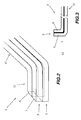
- the C-shaped half-coils comprises an active portion 41, configured to be embedded in a respective rotor slot, and two opposite bent radius winding end portions, of which only bent portion 42 is visible in the figure.
- the half-coil 4 comprises a stack of turns 5 electrically insulated from each other. Each turn 5 of the stack of turns of the half-coil 4 comprises two separate adjacent single conductors 6 and 7. Conductors 6 and 7 are electrically connected to each other in order to assure the flow of current between them.
- each single conductor 6 and 7 of turn 5 is a hollow conductor, having an inner cooling channel running through its axial development (not visible in the figures). Therefore, the positioning side by side of separate single conductors 6 and 7, electrically connected to each other, advantageously ensures the same functionalities of a state-of-the-art double hollow single conductor whilst facilitating the manufacturing process.
- the C-shaped half-coil 8 comprises, in a similar manner, an active portion 81, configured to be embedded in a respective rotor slot, and two opposite bent radius winding end portions, of which only bent portion 82 is visible in the figure.
- the half-coil 8 comprises a stack of turns 5 electrically insulated from each other. Each turn 5 of the stack of turns of the half-coil 8 comprises two separate adjacent single first and second conductors 9 and 10. Conductors 9 and 10 are electrically connected to each other in order to assure the flow of current between them.
- first conductor 9 which is the outer conductor of turn 5
- first conductor 9 running adjacently to the bent portion 82 of conductor 10 allows a substantial reduction of space required in the axial direction for the positioning of the related turn.
- the turn 5 further comprises electrical contact means 11 interposed between adjacent conductors 9 and 10.
- electrical contact means 11 are located substantially in proximity of the axial ends of the first conductor 9.
- first and second conductors 9, 10 of turn 5 may be in electrical contact thought out their length around the rotor body.
- first and second conductors 9 and 10 of the turn 5 may be used in order to electrically connect the first and second conductors 9 and 10 of the turn 5 such as soldering, silvering, friction welding, riveting, screwing, crimping, contact sleeves, contact bridges, contact strips.
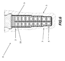
- FIG 6 it is shown a cross-sectional view of a C-shaped half-coil of figures 4 and 5 embedded in a respective rotor slot 3.
- the half-coil formed by a plurality of electrically insulated turns 5 positioned on top of each other.
- Each turn 5 comprises two separate single conductors 9 and 10, positioned side by side and electrically contacted to each other, as specified above.
- separate single conductors 9 and 10 are hollow conductors, having a cooling channel running throughout their length.
- the rotor winding 20 comprises the plurality of C-shaped half-coils 8, each one embedded in a respective rotor slot (not shown) and being joined to a respective opposite half-coil 8' in order to form the complete winding.
- the first inner three half-coils comprises two single conductors 9 and 10 wherein conductors 9 are straight having axial ends in proximity of bent portions of adjacent conductors 10 such that the room required for the rotor winding is sensibly reduced because of absence of radius portions of single conductors 9.
- This way, existing rotor winding having brazed corners can be replaced by a new rotor winding 20 during re-winding operation because of the reduction of axial space thus achieved.
- Figure 8 shows a cross-sectional view along a section line A-A' of figure 8 .
- the figure depicts the single conductors 10 for the first inner half-coils 8 as described above.
- the figure shows a retaining ring of the electrical machine generally indicated with reference 300.
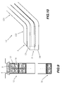
- figure 9 shows a cross-sectional view of a portion of a C-shaped half-coil 12 according to a second preferred embodiment of the present invention.
- the half-coil 12 comprises an active portion 121, configured to be embedded in a respective rotor slot, and two opposite bent radius winding end portions, of which only bent portion 122 is visible in the figure.
- the half-coil 12 comprises a stack of turns 5 electrically insulated from each other. Each turn 5 of the stack of turns of the half-coil 12 comprises two separate adjacent single conductors 13 and 14 forming a turn. Conductors 13 and 14 are electrically connected to each other in order to assure the flow of current between them.
- each single conductor 13 and 14 of turns 5 is a hollow conductor, having an inner cooling channel running through its axial development (not visible in the figure).
- Figure 10 better shows the arrangement of the turns 5 of half-coil 12.
- turns 5 are positioned, in pairs, side by side each one comprising separate single conductors 13 and 14 disposed on top of each other.
- Conductors 13 and 14 are in electric contact between each other, as above specified, whilst turns 5 are electrically insulated in between.
- a last turn 51 at the bottom of the stack may be provided according to the first preferred embodiment, the last turn 51 having single conductors positioned side by side.
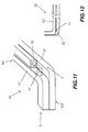
- half-coil 30 comprises, in similar manner, an active portion 301, configured to be embedded in a respective rotor slot, and two opposite bent radius winding end portions, of which only bent portion 302 is visible in the figure.
- the half-coil 30 comprises a stack of turns 5 electrically insulated from each other. Each turn 5 of the stack of turns of the half-coil 30 comprises two separate adjacent single first and second conductors 31 and 32. Conductors 31 and 32 are electrically connected to each other in order to assure the flow of current between them.
- first conductor 31 is a straight shorter conductor having its axial ends protruding outside the respective rotor slot when embedded within the rotor body (not shown), and located in the proximity of respective bent radius portions (in the figure only bent portion 32 is visible).
- Turns 5 are positioned in pairs, side by side. In the portion of the half-coil illustrated, two turns are shown, comprising, respectively, first single straight conductor 31 and second conductor 32 and first single straight conductor 31' and second conductor 32'.
- the arrangement is such that, for each pair of turns positioned side by side, first and second conductors are disposed on top of each other such that the first straight conductor 31 abuts on second conductor 32' of the adjacent turn and second conductor 32 about on the first straight conductor 31'.
- the bent radius portions of second conductor 32 are arranged aligned with corresponding bent radius portions of second conductor 32' of the adjacent turn.
- figure 13 shows a cross sectional view of the half-coil 30 of preceding figures 9 and 10 .
- the turn 51 at the bottom of the stack may be provided in the form of two single separate conductors positioned side by side, as for the first preferred embodiment.
- a copper strip 40 may be provided in different configurations between the two conductors.
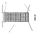
- Last figure 15 shows with more details the principle of the exploitation of the centrifugal forces for ensuring a tight contact between single conductors of the same turn.
- centrifugal forces intensify with the distance of the turn from the centre of the rotor body 2.
- the reaction to the centrifugal forces, which actually keeps conductors in each turn in a forced electrical contact is offered by a rotor slot wedge 110 which encloses the rotor winding.
- the present invention is also directed, with reference to the described figures, to a method for winding a rotor body 2 of an electrical machine 1.
- the winding operation may also be a re-winding, that is removing the existing rotor winding and replacing it with a new one.
- the method according to the invention comprises embedding in each slot 3 of the rotor body a respective conductive C-shaped half-coil, the half-coil comprising an axial active portion running through the slot parallel to a rotating axis R of the rotor body 2, shown in figures 1 and 7 , and two opposite bent radius winding end portions.
- the half-coil comprises a stack of turns electrically insulated from each other, wherein each turn of said stack of turns is provided in the form of two separate single conductors, adjacently positioned along the slot 3 and electrically connected to each other.
- (6) of the two separate single conductors comprise a first single conductor which is a straight conductor and a second conductor of said two separate single conductors is C-shaped comprising two opposite bent radius portions.
- the first conductor protrudes out of the rotor body 2 and has its axial ends located in proximity of respective bent radius portions.
- the turns of at least one half-coil are disposed along a radial direction and the first and second conductors are positioned along a circumferential direction with respect to the rotating axis R of the rotor body 2.
- the first and second conductors of each turn are positioned along a radial direction and the turns of at least a half-coil are positioned, in pairs, along a circumferential direction, such that the first conductor of turn abuts on a second conductor of adjacent turn, wherein the pairs of turns are arranged within the respective slot along a radial direction.
- the method further comprising providing a slot wedge 110 supporting the half-coils such that, during operation, first and second conductor are pressed to each other due to centrifugal forces.
Landscapes
- Engineering & Computer Science (AREA)
- Power Engineering (AREA)
- Manufacturing & Machinery (AREA)
- Windings For Motors And Generators (AREA)
- Manufacture Of Motors, Generators (AREA)
Priority Applications (4)
| Application Number | Priority Date | Filing Date | Title |
|---|---|---|---|
| EP14164161.3A EP2930829A1 (de) | 2014-04-10 | 2014-04-10 | C-förmige oder U-förmige Halbspule, Rotorwicklung mit einer derartigen Halbspule und dazugehöriges Herstellungsverfahren |
| PCT/EP2015/057227 WO2015155096A1 (en) | 2014-04-10 | 2015-04-01 | C-shaped or u-shaped half-coil, rotor winding with such a half-coil and its manufacturing method |
| US15/302,509 US20170033629A1 (en) | 2014-04-10 | 2015-04-01 | C-shaped or u-shaped half-coil, rotor winding with such a half-coil and its manufactuing method |
| CN201580018536.9A CN106416017B (zh) | 2014-04-10 | 2015-04-01 | C形或u形半线圈、有此半线圈的转子绕组和其制造方法 |
Applications Claiming Priority (1)
| Application Number | Priority Date | Filing Date | Title |
|---|---|---|---|
| EP14164161.3A EP2930829A1 (de) | 2014-04-10 | 2014-04-10 | C-förmige oder U-förmige Halbspule, Rotorwicklung mit einer derartigen Halbspule und dazugehöriges Herstellungsverfahren |
Publications (1)
| Publication Number | Publication Date |
|---|---|
| EP2930829A1 true EP2930829A1 (de) | 2015-10-14 |
Family
ID=50442430
Family Applications (1)
| Application Number | Title | Priority Date | Filing Date |
|---|---|---|---|
| EP14164161.3A Withdrawn EP2930829A1 (de) | 2014-04-10 | 2014-04-10 | C-förmige oder U-förmige Halbspule, Rotorwicklung mit einer derartigen Halbspule und dazugehöriges Herstellungsverfahren |
Country Status (4)
| Country | Link |
|---|---|
| US (1) | US20170033629A1 (de) |
| EP (1) | EP2930829A1 (de) |
| CN (1) | CN106416017B (de) |
| WO (1) | WO2015155096A1 (de) |
Families Citing this family (5)
| Publication number | Priority date | Publication date | Assignee | Title |
|---|---|---|---|---|
| US20180367005A1 (en) * | 2017-06-14 | 2018-12-20 | GM Global Technology Operations LLC | Stator assembly with uneven conductors |
| CN111835113A (zh) * | 2020-07-07 | 2020-10-27 | 山东齐鲁电机制造有限公司 | 一种适用于变频启动的重型燃气轮发电机转子线圈结构 |
| DE102020210575B4 (de) | 2020-08-20 | 2022-11-03 | Ford Global Technologies, Llc | Herstellungsverfahren für eine Haarnadelspule |
| US11962205B2 (en) | 2021-03-16 | 2024-04-16 | The Timken Company | Mechanical strength of connection of wound rotor generator/motor |
| US20240063673A1 (en) * | 2022-08-19 | 2024-02-22 | The Timken Company | Transposition coils |
Citations (5)
| Publication number | Priority date | Publication date | Assignee | Title |
|---|---|---|---|---|
| US5804902A (en) * | 1994-04-06 | 1998-09-08 | Hill; Wolfgang | Multi-phase electric machine with joined conductor lanes |
| EP1263117A2 (de) * | 2001-05-21 | 2002-12-04 | Reiner Binder | Ankerwicklung und Verfahren zu deren Herstellung |
| DE10239729A1 (de) * | 2002-08-29 | 2004-03-11 | Robert Bosch Gmbh | Elektrische Drehfeldmaschine |
| EP2246965A2 (de) * | 2009-04-27 | 2010-11-03 | Sensoplan Aktiengesellschaft | Sanierverfahren für den Wickelkopf des Rotors eines elektrischen Generators |
| EP2629402A1 (de) * | 2012-02-20 | 2013-08-21 | Alstom Wind, S.L.U. | Reparaturverfahren einer Generatorwickelung und Bausatz zum Erstellen einer Ersatzspule |
-
2014
- 2014-04-10 EP EP14164161.3A patent/EP2930829A1/de not_active Withdrawn
-
2015
- 2015-04-01 US US15/302,509 patent/US20170033629A1/en not_active Abandoned
- 2015-04-01 CN CN201580018536.9A patent/CN106416017B/zh not_active Expired - Fee Related
- 2015-04-01 WO PCT/EP2015/057227 patent/WO2015155096A1/en not_active Ceased
Patent Citations (5)
| Publication number | Priority date | Publication date | Assignee | Title |
|---|---|---|---|---|
| US5804902A (en) * | 1994-04-06 | 1998-09-08 | Hill; Wolfgang | Multi-phase electric machine with joined conductor lanes |
| EP1263117A2 (de) * | 2001-05-21 | 2002-12-04 | Reiner Binder | Ankerwicklung und Verfahren zu deren Herstellung |
| DE10239729A1 (de) * | 2002-08-29 | 2004-03-11 | Robert Bosch Gmbh | Elektrische Drehfeldmaschine |
| EP2246965A2 (de) * | 2009-04-27 | 2010-11-03 | Sensoplan Aktiengesellschaft | Sanierverfahren für den Wickelkopf des Rotors eines elektrischen Generators |
| EP2629402A1 (de) * | 2012-02-20 | 2013-08-21 | Alstom Wind, S.L.U. | Reparaturverfahren einer Generatorwickelung und Bausatz zum Erstellen einer Ersatzspule |
Also Published As
| Publication number | Publication date |
|---|---|
| CN106416017B (zh) | 2019-10-11 |
| CN106416017A (zh) | 2017-02-15 |
| US20170033629A1 (en) | 2017-02-02 |
| WO2015155096A1 (en) | 2015-10-15 |
Similar Documents
| Publication | Publication Date | Title |
|---|---|---|
| JP5939446B2 (ja) | 固定子及びその固定子を備えた回転電機並びにその固定子の製造方法 | |
| US11309760B2 (en) | Rotary electric machine | |
| JP5942714B2 (ja) | 回転電機 | |
| EP2963786B1 (de) | Stator für elektrische drehmaschinen | |
| JP5237933B2 (ja) | 電気機器のステータのためのバー巻線の製造方法 | |
| US9461527B2 (en) | Multiple conductor winding in stator | |
| JP6137552B2 (ja) | 回転電機 | |
| US20170033629A1 (en) | C-shaped or u-shaped half-coil, rotor winding with such a half-coil and its manufactuing method | |
| JP2014197968A (ja) | 回転電機 | |
| CN112219339B (zh) | 用于旋转电机的定子 | |
| CN113646995A (zh) | 旋转电机的定子 | |
| CN111245164A (zh) | 旋转电机及其制造方法 | |
| CN110571965B (zh) | 旋转电机及其制造方法 | |
| JP2010239739A (ja) | 相間絶縁シート | |
| JP5609211B2 (ja) | 回転電機の固定子及び回転電機の固定子の製造方法 | |
| JP2013062963A (ja) | 回転電機 | |
| US20110241462A1 (en) | Stator for electric rotating machine | |
| CN107078611A (zh) | 具有插接的扁平的卷绕头的转子或定子 | |
| CN111492566A (zh) | 定子的制造方法 | |
| JP2012231638A (ja) | 回転電機ステータ | |
| JP2012029441A (ja) | 回転電機用電機子 | |
| CN111316536A (zh) | 环形多相电机 | |
| JP2016046867A (ja) | 回転電機ステータ | |
| JP6852639B2 (ja) | ステータ | |
| EP2950424A1 (de) | Kammer für Leiter von elektrischen Maschinen |
Legal Events
| Date | Code | Title | Description |
|---|---|---|---|
| PUAI | Public reference made under article 153(3) epc to a published international application that has entered the european phase |
Free format text: ORIGINAL CODE: 0009012 |
|
| 17P | Request for examination filed |
Effective date: 20140410 |
|
| AK | Designated contracting states |
Kind code of ref document: A1 Designated state(s): AL AT BE BG CH CY CZ DE DK EE ES FI FR GB GR HR HU IE IS IT LI LT LU LV MC MK MT NL NO PL PT RO RS SE SI SK SM TR |
|
| AX | Request for extension of the european patent |
Extension state: BA ME |
|
| RAP1 | Party data changed (applicant data changed or rights of an application transferred) |
Owner name: GENERAL ELECTRIC TECHNOLOGY GMBH |
|
| STAA | Information on the status of an ep patent application or granted ep patent |
Free format text: STATUS: THE APPLICATION IS DEEMED TO BE WITHDRAWN |
|
| 18D | Application deemed to be withdrawn |
Effective date: 20191101 |