EP2930959B1 - Lokalisierungsverfahren, antriebstestendgerät und tragbares endgerät - Google Patents
Lokalisierungsverfahren, antriebstestendgerät und tragbares endgerät Download PDFInfo
- Publication number
- EP2930959B1 EP2930959B1 EP14738095.0A EP14738095A EP2930959B1 EP 2930959 B1 EP2930959 B1 EP 2930959B1 EP 14738095 A EP14738095 A EP 14738095A EP 2930959 B1 EP2930959 B1 EP 2930959B1
- Authority
- EP
- European Patent Office
- Prior art keywords
- terminal
- angle
- drive test
- included angle
- gyroscope
- Prior art date
- Legal status (The legal status is an assumption and is not a legal conclusion. Google has not performed a legal analysis and makes no representation as to the accuracy of the status listed.)
- Active
Links
- 238000012360 testing method Methods 0.000 title claims description 75
- 238000000034 method Methods 0.000 title claims description 39
- 238000010586 diagram Methods 0.000 claims description 25
- 238000012937 correction Methods 0.000 claims description 23
- 238000004364 calculation method Methods 0.000 claims description 4
- 208000032365 Electromagnetic interference Diseases 0.000 description 5
- 238000010295 mobile communication Methods 0.000 description 5
- 230000000694 effects Effects 0.000 description 4
- 238000005516 engineering process Methods 0.000 description 3
- 230000003044 adaptive effect Effects 0.000 description 1
- 238000004891 communication Methods 0.000 description 1
- 238000010276 construction Methods 0.000 description 1
- 230000004927 fusion Effects 0.000 description 1
- 238000012986 modification Methods 0.000 description 1
- 230000004048 modification Effects 0.000 description 1
- 238000012806 monitoring device Methods 0.000 description 1
- 230000000630 rising effect Effects 0.000 description 1
- 239000007787 solid Substances 0.000 description 1
- 230000003068 static effect Effects 0.000 description 1
Images


Classifications
-
- H—ELECTRICITY
- H04—ELECTRIC COMMUNICATION TECHNIQUE
- H04W—WIRELESS COMMUNICATION NETWORKS
- H04W4/00—Services specially adapted for wireless communication networks; Facilities therefor
- H04W4/02—Services making use of location information
- H04W4/025—Services making use of location information using location based information parameters
- H04W4/026—Services making use of location information using location based information parameters using orientation information, e.g. compass
-
- G—PHYSICS
- G01—MEASURING; TESTING
- G01C—MEASURING DISTANCES, LEVELS OR BEARINGS; SURVEYING; NAVIGATION; GYROSCOPIC INSTRUMENTS; PHOTOGRAMMETRY OR VIDEOGRAMMETRY
- G01C21/00—Navigation; Navigational instruments not provided for in groups G01C1/00 - G01C19/00
- G01C21/20—Instruments for performing navigational calculations
- G01C21/206—Instruments for performing navigational calculations specially adapted for indoor navigation
-
- G—PHYSICS
- G01—MEASURING; TESTING
- G01C—MEASURING DISTANCES, LEVELS OR BEARINGS; SURVEYING; NAVIGATION; GYROSCOPIC INSTRUMENTS; PHOTOGRAMMETRY OR VIDEOGRAMMETRY
- G01C25/00—Manufacturing, calibrating, cleaning, or repairing instruments or devices referred to in the other groups of this subclass
- G01C25/005—Manufacturing, calibrating, cleaning, or repairing instruments or devices referred to in the other groups of this subclass initial alignment, calibration or starting-up of inertial devices
-
- H—ELECTRICITY
- H04—ELECTRIC COMMUNICATION TECHNIQUE
- H04W—WIRELESS COMMUNICATION NETWORKS
- H04W4/00—Services specially adapted for wireless communication networks; Facilities therefor
- H04W4/02—Services making use of location information
- H04W4/025—Services making use of location information using location based information parameters
-
- H—ELECTRICITY
- H04—ELECTRIC COMMUNICATION TECHNIQUE
- H04W—WIRELESS COMMUNICATION NETWORKS
- H04W4/00—Services specially adapted for wireless communication networks; Facilities therefor
- H04W4/30—Services specially adapted for particular environments, situations or purposes
- H04W4/33—Services specially adapted for particular environments, situations or purposes for indoor environments, e.g. buildings
Definitions
- the present invention relates to the field of communication technologies, and particularly to a locating method, a drive test terminal and a hand-held terminal in an indoor network coverage test.
- indoor network coverage test technologies have been applied in construction of mobile communication network.
- an indoor drive test terminal can realize a collection operation of wireless interface data in relation to multiple modes in accordance with a predefined testing scheme or real-time instructions of a drive test platform;
- a hand-held terminal (such as, tablet PC, mobile phone and notebook) cooperatively used with the indoor drive test terminal may display indoor advancing track.
- the network coverage condition of various indoor positions can be tested.
- the gyroscope generally includes a tri-axial angular velocity meter, a tri-axial accelerometer and a tri-axial magnetometer.
- adaptive Kalman data fusion algorithm is generally adopted. The algorithm necessarily performs indoor location in accordance with a directional angle of the indoor drive test terminal.
- the indoor drive test terminal may set by adopting a deviation between the magnetometer angle and the due north angle in conjunction with the shape of the building, so as to determine the directional angle of the indoor location.
- the existing schemes for indoor location depend on the magnetometer.
- the magnetometer may be interfered to cause the magnetometer to be unreliable and to generate a significant deviation, such that the directional angle of the indoor location could not correctly determined, and then the indoor network coverage test is inaccurate.
- WO 2012/037576 A2 discloses tracking a person in a building performed by obtaining a building layout with respect to a surrounding geography and tracking movement of the person using a monitoring device carried by the person, in which a correction angle can be calculated to normalize tracked movement of the person with respect to a skew angle of the building layout and the correction angle can be applied to the tracked movement of the person or the building layout.
- the present invention provides locating methods, and drive test systems, as defined in the independent claims, for indoor network coverage test, in order to solve problems that the existing schemes for indoor location can not accurately determine the directional angle for indoor location with a great amount of electro-magnetic interference in the indoor environment such that the indoor network coverage test is inaccurate.
- the present invention may have following advantages:
- the directional angle for indoor location may be accurately determined on occasions of a great amount of electro-magnetic interference without using the magnetometer, such that the condition of indoor network coverage may be accurately tested.
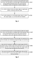
- FIG. 1 shows a flow chart of a locating method according to a first embodiment of the present invention.
- the locating method in this embodiment may comprise the following steps.
- Step S102 a first terminal receives an included angle value between a current advancing direction of a user and a due north direction, which is sent from a second terminal.
- the first terminal is provided with a gyroscope; the second terminal is used to calculate the included angle value of the included angle between the current advancing direction and the due north direction according to the current advancing direction input by the user and a due north direction indication diagram, and send the included angle value to the first terminal.
- Step S104 the first terminal uses the included angle value to correct an output angle of the gyroscope, so as to locate the first terminal.
- the first terminal may use the included angle value to correct it.
- the correction needs to first determine the deviation between the gyroscope and the due north direction.
- a current angle of the gyroscope may be set to 0 degree, then the included angle value may be the deviation between a current direction of the gyroscope and the due north direction, and subsequently the included angle value may be used to correct output angles of the gyroscope during outputting angles; as another example, the current angle of the gyroscope may also be recorded, then the sum of the current angle and the included angle value may be the deviation between the current direction of the gyroscope and the due north direction, and the sum of the current angle and the included angle value may be used to correct the output angles of the gyroscope.
- the present invention is not limited thereto, and other manner of recording deviation and using the deviation to correct output angles of the gyroscope may be also applicable.
- the first terminal provided with the gyroscope may be used as the drive test terminal, and the second terminal may be used as the hand-held terminal, the combination of which may realize location.
- the second terminal may be provided with a due north direction indication diagram, such as a map or an outline diagram of a building, and the second terminal may calculate the included angle value between the current advancing direction input by the user and the due north direction according to the indication diagram and then send the included angle value to the first terminal for correcting an output angle of the gyroscope by the first terminal, so as to realize location.
- the directional angle for indoor location may be accurately determined on occasions of a great amount of electro-magnetic interference without using the magnetometer, such that the condition of indoor network coverage may be accurately tested.
- FIG. 2 shows a flow chart of a locating method according to a second embodiment of the present invention.
- the locating method in this embodiment may comprise the following steps.
- Step S202 a first terminal receives an included angle value between a current advancing direction of a user and a due north direction, which is sent from a second terminal.
- the first terminal is provided with a gyroscope; the second terminal is used to calculate the included angle value of the included angle between the current advancing direction and the due north direction according to the current advancing direction input by the user and a due north direction indication diagram, and sent the included angle value to the first terminal.
- Step S204 the first terminal sets a current angle of the gyroscope to 0 degree when receiving the included angle value.
- Step S206 when outputting angle, the first terminal uses the sum of a current to-be-output angle of the gyroscope and the included angle value as a corrected output angle, to locate the first terminal.
- the directional angle for indoor location may be accurately determined on occasions of a great amount of electro-magnetic interference without using the magnetometer to locate the drive test terminal, such that the condition of indoor network coverage may be accurately tested.
- FIG. 3 shows a flow chart of a locating method according to a third embodiment of the present invention.
- the locating method in this embodiment corresponds to the locating methods in the first and second embodiments, and may comprise the following steps.
- Step S302 a second terminal receives a current advancing direction input by a user, and calculates an included angle value between the current advancing direction and a due north direction according to a due north direction indication diagram.
- the second terminal may provide an interface for inputting by the user.
- the user may input the current advancing direction by any suitable manners. For example, the user may input by touching a touch screen, or the user may input by selecting selectable routes provided according to practical situations.
- the due north direction indication diagram may adopt any suitable forms, such as outline drawings or maps of buildings.
- An identifier for indicating the due north direction is generally provided in the diagrams or the maps. For example, after the user inputs the current advancing direction in an outline drawing of a building, the identifier for indicating the due north direction could be used to calculate the included angle value between the current advancing direction and the due north direction.
- Step S304 the second terminal receives an output angle of a gyroscope, which is sent from a first terminal.
- the second terminal may acquire the output angle of the first terminal to calculate a deviation between the gyroscope and the due north direction.
- Step S306 the second terminal uses the included angle value to correct the output angle, so as to locate the first terminal.
- the use of the included angle value to correct the output angle may determine the deviation between the gyroscope of the first terminal and the due north direction, so as to accurately correct the first terminal.
- the second terminal may be provided with a corresponding application or device to receive user's input, to calculate the included angle value between the current advancing direction and the due north direction, and to correct the output angle of the gyroscope of the first terminal, such that on the one hand, the location of the first terminal does not necessarily depend on the magnetometer; on the other hand, the first terminal can be accurately located without any modification.
- the indoor locating directional angle can be accurately determined, such that the condition of indoor network coverage can be accurately tested.
- FIG. 4 shows a flow chart of a locating method according to a fourth embodiment of the present invention.
- the locating method in this embodiment is a further preferred scheme based on the locating method in the third embodiment, and may comprise the following steps.
- Step S402 a second terminal receives a current advancing direction input by a user, and calculates an included angle value between the current advancing direction and a due north direction according to a due north direction indication diagram.
- the user may also input a current initial point
- the second terminal may receive the current initial point input by the user to determine the initial point of advance track of the user, in order for the advance location.
- Step S404 the second terminal acquires a current angle of a gyroscope of a first terminal, and records the acquired angle as a correction angle.
- Step S406 when the first terminal is required to output angle, the first terminal sends an output angle of the gyroscope to the second terminal, and the second terminal receives the output angle of the gyroscope sent from the first terminal.
- Step S408 the second terminal uses the included angle value and the correction angle to correct the output angle, so as to locate the first terminal.
- This step may comprise: the second terminal using a difference obtained by subtracting the correction angle from the sum of the output angle and the included angle value as a corrected angle.
- the indoor locating directional angle can be accurately determined, such that the condition of indoor network coverage can be accurately tested.
- FIG. 5 shows a flow chart of a locating method according to a fifth embodiment of the present invention.
- This indoor network coverage test desirably uses a first terminal having a gyroscope in cooperation with a second terminal to perform indoor location.
- This embodiment will describe the locating method of the present invention by way of combining operations of the first terminal and the second terminal.
- the first terminal is a drive test terminal, which is provided with a gyroscope;
- the second terminal is a hand-held terminal, which provides an interface for inputting relevant locating parameters for a user.
- the locating method in this embodiment may comprise the following steps.
- Step S502 the gyroscope of the drive test terminal is energized, and the drive test terminal records an initial directional angle of 0 degree.
- the energized gyroscope is required to keep a static status. At this point, an angular accelerometer of the gyroscope is reset, and the angle of 0 degree is set to a current direction. At this point, the angle of 0 degree is randomly set and can not be used for indoor location, and an included angle between the angle of 0 degree and the due north direction is unknown.
- Step S504 the hand-held terminal receives a current initial point and a current advancing direction, which are input by a user.
- the user may select the current initial point and then select the advancing direction on the hand-held terminal (such as, tablet PC, notebook and mobile phone).
- the advancing direction may be determined by the user according to diagrams of buildings.
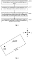
- Input of the current initial point and the current advancing direction by the hand-held terminal is shown in Figure 6 , wherein the periphery frame is a schematic boundary of a building.
- the user may click within the boundary to select the current initial point to locate a position, and then select the advancing direction, as indicated in an arrow in the Figure.
- directional symbols of the building are provided in the Figure, indicating four directions of east, west, north and south of the building.
- Step S506 the hand-held terminal calculates an included angle between the current advancing direction and the due north direction according to the current advancing direction input by the user.
- the hand-held terminal may calculate the included angle between a route of the advancing direction and the due north direction according to the selected advancing direction, and an angular value of the included angle is recorded as a.
- Step S508 an angular value of the included angle is used to correct an output angle of the gyroscope of the drive test terminal, so as to perform indoor location.
- the output angle of the gyroscope of the drive test terminal can be corrected by following two schemes:
- the judgement of advancing angle of a body is very important.
- a proper configuration of the included angle between the advancing angle and the due north direction is able to assist in accurately taking on the indoor location track.
- the angle of the gyroscope can be simply and rapidly set by the hand-held terminal, outline drawings of buildings, the gyroscope and etc.
- the hand-held terminal and outline drawings of buildings are auxiliarily used to set the directional angle of the gyroscope.
- the gyroscope may directly output the included angle relative to the due north direction, or the hand-held terminal may calculate the included angle relative to the due north direction according to relevant information.
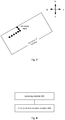
- FIG. 8 shows a block diagram of a drive test terminal according to a sixth embodiment of the present invention.
- the drive test terminal in this embodiment may include: a receiving module 602, configured to receive an included angle value between a current advancing direction of a user and a due north direction, which is sent from a hand-held terminal, wherein the drive test terminal is provided with a gyroscope, and the hand-held terminal is used to calculate the included angle value of the included angle between the current advancing direction and the due north direction according to the current advancing direction input by the user and a due north direction indication diagram, and send the included angle value to the drive test terminal; a first correction location module 604, configured to use the included angle value to correct an output angle of the gyroscope, so as to locate the drive test terminal.
- the receiving module 602 is further configured to, when receiving the included angle value, set a current angle of the gyroscope to 0 degree; the first correction location module 604 is configured to, when outputting angle, use the sum of a current to-be-output angle of the gyroscope and the included angle value as a corrected output angle, to locate the drive test terminal.
- the drive test terminal in this embodiment may be used to realize the corresponding locating methods of the drive test terminal in the method embodiments as described above, and have advantageous effects corresponding to the method embodiments, the description of which will be omitted herein.
- FIG. 9 shows a block diagram of a hand-held terminal according to a seventh embodiment of the present invention.
- the hand-held terminal in this embodiment may include: a calculation module 702, configured to receive a current advancing direction input by a user, and calculate an included angle value between the current advancing direction and a due north direction according to a due north direction indication diagram; a receiving module 704, configured to receive an output angle of a gyroscope, which is sent from a drive test terminal; a second correction location module 706, configured to use the included angle value to correct the output angle, so as to locate the drive test terminal.
- a calculation module 702 configured to receive a current advancing direction input by a user, and calculate an included angle value between the current advancing direction and a due north direction according to a due north direction indication diagram
- a receiving module 704 configured to receive an output angle of a gyroscope, which is sent from a drive test terminal
- a second correction location module 706, configured to use the included angle value to correct the output angle, so as to locate the drive test terminal.
- the hand-held terminal in this embodiment may further include: a recording module 708, configured to, after the calculation module 702 receives the current advancing direction input by the user and calculates the included angle value between the current advancing direction and the due north direction according to the due north direction indication diagram, acquire a current angle of the gyroscope of the drive test terminal, and record the acquired angle as a correction angle; the second correction location module 706, configured to use a difference obtained by subtracting the correction angle from the sum of the output angle and the included angle value as a corrected angle, and use the corrected angle to locate the drive test terminal.
- a recording module 708 configured to, after the calculation module 702 receives the current advancing direction input by the user and calculates the included angle value between the current advancing direction and the due north direction according to the due north direction indication diagram, acquire a current angle of the gyroscope of the drive test terminal, and record the acquired angle as a correction angle
- the second correction location module 706 configured to use a difference obtained by subtracting the correction angle from the sum
- the hand-held terminal in this embodiment may be used to realize the corresponding locating methods of the hand-held terminal in the method embodiments as described above, and have advantageous effects corresponding to the method embodiments, the description of which will be omitted herein.
Landscapes
- Engineering & Computer Science (AREA)
- Radar, Positioning & Navigation (AREA)
- Remote Sensing (AREA)
- Computer Networks & Wireless Communication (AREA)
- Signal Processing (AREA)
- Physics & Mathematics (AREA)
- General Physics & Mathematics (AREA)
- Manufacturing & Machinery (AREA)
- Automation & Control Theory (AREA)
- Navigation (AREA)
- Telephone Function (AREA)
- Gyroscopes (AREA)
Claims (10)
- Lokalisierungsverfahren zum Testen der Netzabdeckung in Innenräumen, das umfasst, dass:ein tragbares Endgerät einen Einschlusswinkelwert eines Einschlusswinkels zwischen einer aktuellen Vorwärtsbewegungsrichtung eines Nutzers und einer genauen Nordrichtung gemäß der aktuellen Vorwärtsbewegungsrichtung, die von dem Nutzer eingegeben wird, und einem Diagramm zur Anzeige der genauen Nordrichtung berechnet und den Einschlusswinkelwert an ein Fahrtestendgerät sendet; unddas Fahrtestendgerät den Einschlusswinkelwert empfängt (S102) und das Fahrtestendgerät den Einschlusswinkelwert verwendet (S104), um einen Ausgabewinkel eines Gyroskops zu korrigieren, das in dem Fahrtestendgerät bereitgestellt ist, um das Fahrtestendgerät zu lokalisieren.
- Verfahren nach Anspruch 1, wobei das Verfahren ferner umfasst, dass:
das Fahrtestendgerät einen aktuellen Winkel des Gyroskops auf 0 Grad setzt (S204), wenn der Einschlusswinkelwert empfangen wird. - Verfahren nach Anspruch 1, wobei der Schritt, dass das Fahrtestendgerät den Einschlusswinkelwert verwendet (S104), um einen Ausgabewinkel des Gyroskops zu korrigieren, umfasst, dass:
wenn ein Winkel ausgegeben wird, das Fahrtestendgerät die Summe aus einem aktuell auszugebenden Winkel des Gyroskops und dem Einschlusswinkelwert als korrigierten Ausgabewinkel verwendet (S206). - Lokalisierungsverfahren zum Testen der Netzabdeckung in Innenräumen, das umfasst, dass:ein tragbares Endgerät eine aktuelle Vorwärtsbewegungsrichtung eines Nutzers, die von dem Nutzer eingegeben wird, empfängt (S302) und einen Einschlusswinkelwert zwischen der aktuellen Vorwärtsbewegungsrichtung und einer genauen Nordrichtung gemäß einem Diagramm zur Anzeige der genauen Nordrichtung berechnet (S302);das tragbare Endgerät von einem Fahrtestendgerät einen Ausgabewinkel eines Gyroskops, das in dem Fahrtestendgerät bereitgestellt ist, empfängt (S304), unddas tragbare Endgerät den Einschlusswinkelwert zur Korrektur des Ausgabewinkels verwendet (S306), um das Fahrtestendgerät zu lokalisieren.
- Verfahren nach Anspruch 4, wobei
das Verfahren nach dem Schritt, dass das tragbare Endgerät die aktuelle Vorwärtsbewegungsrichtung, die von dem Nutzer eingegeben wird, empfängt (S302) und den Einschlusswinkelwert zwischen der aktuellen Vorwärtsbewegungsrichtung und der genauen Nordrichtung gemäß dem Diagramm zur Anzeige der genauen Nordrichtung berechnet (S302), ferner umfasst, dass:das tragbare Endgerät einen aktuellen Winkel des Gyroskops des Fahrtestendgeräts beschafft und den beschafften Winkel als Korrekturwinkel aufzeichnet; undder Schritt, dass das tragbare Endgerät den Einschlusswinkelwert zur Korrektur des Ausgabewinkels verwendet (S306), umfasst, dass:
das tragbare Endgerät den Einschlusswinkelwert und den Korrekturwinkel zur Korrektur des Ausgabewinkels verwendet (S408). - Verfahren nach Anspruch 5, wobei der Schritt, dass das tragbare Endgerät den Einschlusswinkelwert und den Korrekturwinkel zur Korrektur des Ausgabewinkels verwendet (S408), umfasst, dass:
das tragbare Endgerät eine Differenz, die durch Subtraktion des Korrekturwinkels von der Summe des Ausgabewinkels und des Einschlusswinkelwerts erhalten wird, als korrigierten Winkel verwendet. - Fahrtestsystem zum Testen der Netzabdeckung in Innenräumen, das ein Fahrtestendgerät und ein tragbares Endgerät enthält, wobeidas tragbare Endgerät konfiguriert ist, um einen Einschlusswinkelwert eines Einschlusswinkels zwischen einer aktuellen Vorwärtsbewegungsrichtung eines Nutzers und einer genauen Nordrichtung gemäß der aktuellen Vorwärtsbewegungsrichtung, die von dem Nutzer eingegeben wird, und einem Anzeigediagramm für die genaue Nordrichtung zu berechnen und den Einschlusswinkelwert an das Fahrtestendgerät zu senden;das Fahrtestendgerät mit einem Gyroskop ausgestattet ist und umfasst:ein Empfangsmodul (602), das konfiguriert ist, um den Einschlusswinkelwert zu empfangen; undein erstes Lokalisierungskorrekturmodul (604), das konfiguriert ist, um den Einschlusswinkelwert zur Korrektur eines Ausgabewinkels des Gyroskops zu verwenden, um das Fahrtestendgerät zu lokalisieren.
- Fahrtestsystem nach Anspruch 7, wobei das Empfangsmodul (602) ferner konfiguriert ist, um einen aktuellen Winkel des Gyroskops auf 0 Grad einzustellen, wenn es den Einschlusswinkelwert empfängt;
das erste Lokalisierungskorrekturmodul (604) konfiguriert ist, um bei der Ausgabe eines Winkels die Summe aus einem aktuell auszugebenden Winkel des Gyroskops und dem Einschlusswinkelwert als korrigierten Ausgabewinkel zu verwenden, um das Fahrtestendgerät zu lokalisieren. - Fahrtestsystem zum Testen der Netzabdeckung in Innenräumen, das ein Fahrtestendgerät mit einem Gyroskop und ein tragbares Endgerät umfasst, wobei das tragbare Endgerät umfasst:ein Berechnungsmodul (702), das konfiguriert ist, um eine aktuelle Vorwärtsbewegungsrichtung eines Nutzers, die von dem Nutzer eingegeben wird, zu empfangen, und um einen Einschlusswinkelwert zwischen der aktuellen Vorwärtsbewegungsrichtung und einer genauen Nordrichtung gemäß einem Anzeigediagramm für die genaue Nordrichtung zu berechnen;ein Empfangsmodul (704), das konfiguriert ist, um einen Ausgabewinkel des Gyroskops zu empfangen, der von dem Fahrtestendgerät gesendet wird; undein zweites Lokalisierungskorrekturmodul (706), das konfiguriert ist, um den Einschlusswinkelwert zur Korrektur des Ausgabewinkels zu verwenden, um das Fahrtestendgerät zu lokalisieren.
- Fahrtestsystem nach Anspruch 9, wobei das tragbare Endgerät ferner umfasst:ein Aufzeichnungsmodul (708), das konfiguriert ist, um, nachdem das Berechnungsmodul die aktuelle Vorwärtsbewegungsrichtung, die von dem Nutzer eingegeben wird, empfängt und den Einschlusswinkelwert zwischen der aktuellen Vorwärtsbewegungsrichtung und der genauen Nordrichtung gemäß dem Anzeigediagramm der genauen Nordrichtung berechnet, einen aktuellen Winkel des Gyroskops des Fahrtestendgeräts zu beschaffen und den beschafften Winkel als Korrekturwinkel aufzuzeichnen; unddas zweite Lokalisierungskorrekturmodul (706) konfiguriert ist, um eine Differenz zu verwenden, die durch Subtraktion des Korrekturwinkels von der Summe des Ausgabewinkels und des Einschlusswinkelwerts als korrigierter Winkel erhalten wird, und um den korrigierten Winkel zur Lokalisierung des Fahrtestendgeräts zu verwenden.
Applications Claiming Priority (2)
| Application Number | Priority Date | Filing Date | Title |
|---|---|---|---|
| CN201310008342.3A CN103091662B (zh) | 2013-01-09 | 2013-01-09 | 定位方法、路测终端与手持终端 |
| PCT/CN2014/070066 WO2014108045A1 (zh) | 2013-01-09 | 2014-01-03 | 定位方法、路测终端与手持终端 |
Publications (3)
| Publication Number | Publication Date |
|---|---|
| EP2930959A1 EP2930959A1 (de) | 2015-10-14 |
| EP2930959A4 EP2930959A4 (de) | 2016-07-20 |
| EP2930959B1 true EP2930959B1 (de) | 2020-05-06 |
Family
ID=48204465
Family Applications (1)
| Application Number | Title | Priority Date | Filing Date |
|---|---|---|---|
| EP14738095.0A Active EP2930959B1 (de) | 2013-01-09 | 2014-01-03 | Lokalisierungsverfahren, antriebstestendgerät und tragbares endgerät |
Country Status (4)
| Country | Link |
|---|---|
| US (1) | US9554253B2 (de) |
| EP (1) | EP2930959B1 (de) |
| CN (1) | CN103091662B (de) |
| WO (1) | WO2014108045A1 (de) |
Families Citing this family (10)
| Publication number | Priority date | Publication date | Assignee | Title |
|---|---|---|---|---|
| CN103091662B (zh) * | 2013-01-09 | 2015-08-05 | 上海大唐移动通信设备有限公司 | 定位方法、路测终端与手持终端 |
| CN103354646B (zh) * | 2013-06-28 | 2017-06-27 | 北京神州泰岳软件股份有限公司 | 扫频方法、系统和设备 |
| EP2955860B1 (de) | 2014-04-22 | 2018-06-27 | Huawei Device (Dongguan) Co., Ltd. | Datenauswahlverfahren und -vorrichtung |
| EP3214863B1 (de) * | 2014-11-25 | 2020-04-01 | Huawei Technologies Co., Ltd. | Ausrichtungsverfahren, -vorrichtung und -system |
| CN106657575B (zh) * | 2016-09-23 | 2019-06-28 | 深圳智芯数据服务有限公司 | 一种智能手表的地磁功能控制方法及其控制系统 |
| CN107576335B (zh) * | 2017-09-04 | 2020-12-25 | 红栗子虚拟现实(北京)科技有限公司 | 一种基于大空间的惯性动作捕捉变形与扭曲校正方法和装置 |
| US11140519B1 (en) * | 2020-09-29 | 2021-10-05 | Isharingsoft, Inc. | Bandwidth efficient location tracking |
| CN113280835A (zh) * | 2021-05-20 | 2021-08-20 | 北京智慧图科技有限责任公司 | 一种基于路径规划的室内定位校正方法 |
| CN113240824B (zh) * | 2021-07-08 | 2021-10-29 | 太平金融科技服务(上海)有限公司深圳分公司 | 考勤方法、装置、计算机设备和存储介质 |
| CN115855106A (zh) * | 2022-11-22 | 2023-03-28 | 珠海亿智电子科技有限公司 | 摄像头和陀螺仪夹角的在线标定方法、装置和存储介质 |
Family Cites Families (15)
| Publication number | Priority date | Publication date | Assignee | Title |
|---|---|---|---|---|
| US6366856B1 (en) * | 2000-11-21 | 2002-04-02 | Qualcomm Incorporated | Method and apparatus for orienting a map display in a mobile or portable device |
| US8797260B2 (en) * | 2002-07-27 | 2014-08-05 | Sony Computer Entertainment Inc. | Inertially trackable hand-held controller |
| KR100648342B1 (ko) * | 2003-02-10 | 2006-11-23 | 엘지전자 주식회사 | 네비게이션 시스템 및 그 동작 방법 |
| CN100480631C (zh) * | 2004-07-16 | 2009-04-22 | 张驰 | 高精度自动陀螺全能仪及构成方法 |
| CN100367004C (zh) * | 2006-03-27 | 2008-02-06 | 北京航空航天大学 | 一种陀螺仪标度因数和输入轴失准角的精确解耦测试方法 |
| US7412775B1 (en) * | 2007-08-03 | 2008-08-19 | Honeywell International Inc. | Gyroscope north seeker system and method |
| US8200436B2 (en) * | 2009-07-15 | 2012-06-12 | Schlumberger Technology Corporation | Method and apparatus for wellbore survey using inertial sensors |
| US9222784B2 (en) * | 2010-09-17 | 2015-12-29 | Myles L. Strohl | Building perpendicularity testing and adjustment |
| CN102457807A (zh) * | 2010-10-20 | 2012-05-16 | 大唐移动通信设备有限公司 | 一种确定位置信息的方法和终端 |
| CN102419180B (zh) * | 2011-09-02 | 2014-01-01 | 无锡智感星际科技有限公司 | 一种基于惯性导航系统和wifi的室内定位方法 |
| EP2578992B1 (de) * | 2011-10-06 | 2017-01-25 | Vectronix AG | Geographisch nordreferenzierte Azimutbestimmung |
| CN102506837A (zh) | 2011-10-10 | 2012-06-20 | 海能达通信股份有限公司 | 终端定位方法及带有电子罗盘的终端 |
| US9562764B2 (en) * | 2012-07-23 | 2017-02-07 | Trimble Inc. | Use of a sky polarization sensor for absolute orientation determination in position determining systems |
| CN103091662B (zh) | 2013-01-09 | 2015-08-05 | 上海大唐移动通信设备有限公司 | 定位方法、路测终端与手持终端 |
| US10132829B2 (en) * | 2013-03-13 | 2018-11-20 | Invensense, Inc. | Heading confidence interval estimation |
-
2013
- 2013-01-09 CN CN201310008342.3A patent/CN103091662B/zh active Active
-
2014
- 2014-01-03 EP EP14738095.0A patent/EP2930959B1/de active Active
- 2014-01-03 WO PCT/CN2014/070066 patent/WO2014108045A1/zh not_active Ceased
- 2014-01-03 US US14/759,416 patent/US9554253B2/en active Active
Non-Patent Citations (1)
| Title |
|---|
| None * |
Also Published As
| Publication number | Publication date |
|---|---|
| US20150358784A1 (en) | 2015-12-10 |
| EP2930959A1 (de) | 2015-10-14 |
| US9554253B2 (en) | 2017-01-24 |
| CN103091662B (zh) | 2015-08-05 |
| CN103091662A (zh) | 2013-05-08 |
| WO2014108045A1 (zh) | 2014-07-17 |
| EP2930959A4 (de) | 2016-07-20 |
Similar Documents
| Publication | Publication Date | Title |
|---|---|---|
| EP2930959B1 (de) | Lokalisierungsverfahren, antriebstestendgerät und tragbares endgerät | |
| US9080874B2 (en) | Generating magnetic field map for indoor positioning | |
| KR102252566B1 (ko) | 로케이션 서비스를 개선하기 위해 3차원 로케이션 정보를 사용하기 위한 시스템 및 방법 | |
| CN103797376B (zh) | 用于收集与接入点有关的信息的装置和方法 | |
| US9769622B2 (en) | Indoor location survey assisted by a motion path on a venue map | |
| AU2006330744B2 (en) | Method and apparatus of obtaining improved location accuracy using magnetic field mapping | |
| EP2925064A1 (de) | Verfahren und vorrichtung zur lokalisierung eines mobilfunkgeräts durch orientierung eines mobilgeräts | |
| US11016198B2 (en) | Broadcast transmission of information indicative of a pseudorange correction | |
| CN103560813A (zh) | 一种基于蓝牙技术的移动终端定位方法及装置 | |
| CN105527643A (zh) | 移动终端的定位方法和移动终端 | |
| JP2013205226A (ja) | 位置補正システム、位置補正方法、位置情報サーバ、及び、プログラム | |
| JP2016522403A (ja) | モバイルデバイスロケーションの精度および/または不確実性を特徴づけ、それらに影響を及ぼすための方法および装置 | |
| CN107003128A (zh) | 无线定位系统、无线定位终端以及地点信息发送装置 | |
| KR20120071291A (ko) | 무선통신을 이용하여 실내 위치를 측정하기 위한 실내 위치 측정 장치 및 방법 | |
| CN106332275A (zh) | 定位的方法及装置 | |
| CN106840162A (zh) | 基于惯导的室内路径匹配方法 | |
| CN102884815B (zh) | 确定视线中的对象的方法和设备 | |
| KR20150107056A (ko) | 실내 위치 추정 장치 및 방법 | |
| EP3246723A1 (de) | Verfahren zum einrichten eines positionierungssystems | |
| CN111337874A (zh) | 一种基于地理编码辅助的室内定位方法 | |
| CN108235256B (zh) | 一种基于slam的复合定位方法、装置及存储介质 | |
| Gupta et al. | Pedestrian tracking algorithm in NLOS environments |
Legal Events
| Date | Code | Title | Description |
|---|---|---|---|
| PUAI | Public reference made under article 153(3) epc to a published international application that has entered the european phase |
Free format text: ORIGINAL CODE: 0009012 |
|
| 17P | Request for examination filed |
Effective date: 20150708 |
|
| AK | Designated contracting states |
Kind code of ref document: A1 Designated state(s): AL AT BE BG CH CY CZ DE DK EE ES FI FR GB GR HR HU IE IS IT LI LT LU LV MC MK MT NL NO PL PT RO RS SE SI SK SM TR |
|
| AX | Request for extension of the european patent |
Extension state: BA ME |
|
| DAX | Request for extension of the european patent (deleted) | ||
| RA4 | Supplementary search report drawn up and despatched (corrected) |
Effective date: 20160617 |
|
| RIC1 | Information provided on ipc code assigned before grant |
Ipc: G01C 21/20 20060101ALI20160613BHEP Ipc: H04W 4/02 20090101ALI20160613BHEP Ipc: G01C 25/00 20060101ALI20160613BHEP Ipc: H04W 4/04 20090101AFI20160613BHEP |
|
| STAA | Information on the status of an ep patent application or granted ep patent |
Free format text: STATUS: EXAMINATION IS IN PROGRESS |
|
| 17Q | First examination report despatched |
Effective date: 20181029 |
|
| REG | Reference to a national code |
Ref country code: DE Ref legal event code: R079 Ref document number: 602014064962 Country of ref document: DE Free format text: PREVIOUS MAIN CLASS: H04W0004040000 Ipc: G01C0021200000 |
|
| GRAP | Despatch of communication of intention to grant a patent |
Free format text: ORIGINAL CODE: EPIDOSNIGR1 |
|
| STAA | Information on the status of an ep patent application or granted ep patent |
Free format text: STATUS: GRANT OF PATENT IS INTENDED |
|
| RIC1 | Information provided on ipc code assigned before grant |
Ipc: G01C 21/20 20060101AFI20200203BHEP Ipc: G01C 25/00 20060101ALI20200203BHEP Ipc: H04W 4/02 20180101ALI20200203BHEP |
|
| INTG | Intention to grant announced |
Effective date: 20200228 |
|
| GRAS | Grant fee paid |
Free format text: ORIGINAL CODE: EPIDOSNIGR3 |
|
| GRAA | (expected) grant |
Free format text: ORIGINAL CODE: 0009210 |
|
| STAA | Information on the status of an ep patent application or granted ep patent |
Free format text: STATUS: THE PATENT HAS BEEN GRANTED |
|
| AK | Designated contracting states |
Kind code of ref document: B1 Designated state(s): AL AT BE BG CH CY CZ DE DK EE ES FI FR GB GR HR HU IE IS IT LI LT LU LV MC MK MT NL NO PL PT RO RS SE SI SK SM TR |
|
| REG | Reference to a national code |
Ref country code: GB Ref legal event code: FG4D |
|
| REG | Reference to a national code |
Ref country code: AT Ref legal event code: REF Ref document number: 1267478 Country of ref document: AT Kind code of ref document: T Effective date: 20200515 Ref country code: CH Ref legal event code: EP |
|
| REG | Reference to a national code |
Ref country code: IE Ref legal event code: FG4D |
|
| REG | Reference to a national code |
Ref country code: DE Ref legal event code: R096 Ref document number: 602014064962 Country of ref document: DE |
|
| REG | Reference to a national code |
Ref country code: LT Ref legal event code: MG4D |
|
| REG | Reference to a national code |
Ref country code: NL Ref legal event code: MP Effective date: 20200506 |
|
| PG25 | Lapsed in a contracting state [announced via postgrant information from national office to epo] |
Ref country code: SE Free format text: LAPSE BECAUSE OF FAILURE TO SUBMIT A TRANSLATION OF THE DESCRIPTION OR TO PAY THE FEE WITHIN THE PRESCRIBED TIME-LIMIT Effective date: 20200506 Ref country code: FI Free format text: LAPSE BECAUSE OF FAILURE TO SUBMIT A TRANSLATION OF THE DESCRIPTION OR TO PAY THE FEE WITHIN THE PRESCRIBED TIME-LIMIT Effective date: 20200506 Ref country code: GR Free format text: LAPSE BECAUSE OF FAILURE TO SUBMIT A TRANSLATION OF THE DESCRIPTION OR TO PAY THE FEE WITHIN THE PRESCRIBED TIME-LIMIT Effective date: 20200807 Ref country code: NO Free format text: LAPSE BECAUSE OF FAILURE TO SUBMIT A TRANSLATION OF THE DESCRIPTION OR TO PAY THE FEE WITHIN THE PRESCRIBED TIME-LIMIT Effective date: 20200806 Ref country code: PT Free format text: LAPSE BECAUSE OF FAILURE TO SUBMIT A TRANSLATION OF THE DESCRIPTION OR TO PAY THE FEE WITHIN THE PRESCRIBED TIME-LIMIT Effective date: 20200907 Ref country code: IS Free format text: LAPSE BECAUSE OF FAILURE TO SUBMIT A TRANSLATION OF THE DESCRIPTION OR TO PAY THE FEE WITHIN THE PRESCRIBED TIME-LIMIT Effective date: 20200906 Ref country code: LT Free format text: LAPSE BECAUSE OF FAILURE TO SUBMIT A TRANSLATION OF THE DESCRIPTION OR TO PAY THE FEE WITHIN THE PRESCRIBED TIME-LIMIT Effective date: 20200506 |
|
| PG25 | Lapsed in a contracting state [announced via postgrant information from national office to epo] |
Ref country code: BG Free format text: LAPSE BECAUSE OF FAILURE TO SUBMIT A TRANSLATION OF THE DESCRIPTION OR TO PAY THE FEE WITHIN THE PRESCRIBED TIME-LIMIT Effective date: 20200806 Ref country code: HR Free format text: LAPSE BECAUSE OF FAILURE TO SUBMIT A TRANSLATION OF THE DESCRIPTION OR TO PAY THE FEE WITHIN THE PRESCRIBED TIME-LIMIT Effective date: 20200506 Ref country code: RS Free format text: LAPSE BECAUSE OF FAILURE TO SUBMIT A TRANSLATION OF THE DESCRIPTION OR TO PAY THE FEE WITHIN THE PRESCRIBED TIME-LIMIT Effective date: 20200506 Ref country code: LV Free format text: LAPSE BECAUSE OF FAILURE TO SUBMIT A TRANSLATION OF THE DESCRIPTION OR TO PAY THE FEE WITHIN THE PRESCRIBED TIME-LIMIT Effective date: 20200506 |
|
| REG | Reference to a national code |
Ref country code: AT Ref legal event code: MK05 Ref document number: 1267478 Country of ref document: AT Kind code of ref document: T Effective date: 20200506 |
|
| PG25 | Lapsed in a contracting state [announced via postgrant information from national office to epo] |
Ref country code: NL Free format text: LAPSE BECAUSE OF FAILURE TO SUBMIT A TRANSLATION OF THE DESCRIPTION OR TO PAY THE FEE WITHIN THE PRESCRIBED TIME-LIMIT Effective date: 20200506 Ref country code: AL Free format text: LAPSE BECAUSE OF FAILURE TO SUBMIT A TRANSLATION OF THE DESCRIPTION OR TO PAY THE FEE WITHIN THE PRESCRIBED TIME-LIMIT Effective date: 20200506 |
|
| PG25 | Lapsed in a contracting state [announced via postgrant information from national office to epo] |
Ref country code: AT Free format text: LAPSE BECAUSE OF FAILURE TO SUBMIT A TRANSLATION OF THE DESCRIPTION OR TO PAY THE FEE WITHIN THE PRESCRIBED TIME-LIMIT Effective date: 20200506 Ref country code: SM Free format text: LAPSE BECAUSE OF FAILURE TO SUBMIT A TRANSLATION OF THE DESCRIPTION OR TO PAY THE FEE WITHIN THE PRESCRIBED TIME-LIMIT Effective date: 20200506 Ref country code: EE Free format text: LAPSE BECAUSE OF FAILURE TO SUBMIT A TRANSLATION OF THE DESCRIPTION OR TO PAY THE FEE WITHIN THE PRESCRIBED TIME-LIMIT Effective date: 20200506 Ref country code: DK Free format text: LAPSE BECAUSE OF FAILURE TO SUBMIT A TRANSLATION OF THE DESCRIPTION OR TO PAY THE FEE WITHIN THE PRESCRIBED TIME-LIMIT Effective date: 20200506 Ref country code: RO Free format text: LAPSE BECAUSE OF FAILURE TO SUBMIT A TRANSLATION OF THE DESCRIPTION OR TO PAY THE FEE WITHIN THE PRESCRIBED TIME-LIMIT Effective date: 20200506 Ref country code: ES Free format text: LAPSE BECAUSE OF FAILURE TO SUBMIT A TRANSLATION OF THE DESCRIPTION OR TO PAY THE FEE WITHIN THE PRESCRIBED TIME-LIMIT Effective date: 20200506 Ref country code: IT Free format text: LAPSE BECAUSE OF FAILURE TO SUBMIT A TRANSLATION OF THE DESCRIPTION OR TO PAY THE FEE WITHIN THE PRESCRIBED TIME-LIMIT Effective date: 20200506 Ref country code: CZ Free format text: LAPSE BECAUSE OF FAILURE TO SUBMIT A TRANSLATION OF THE DESCRIPTION OR TO PAY THE FEE WITHIN THE PRESCRIBED TIME-LIMIT Effective date: 20200506 |
|
| REG | Reference to a national code |
Ref country code: DE Ref legal event code: R097 Ref document number: 602014064962 Country of ref document: DE |
|
| PG25 | Lapsed in a contracting state [announced via postgrant information from national office to epo] |
Ref country code: PL Free format text: LAPSE BECAUSE OF FAILURE TO SUBMIT A TRANSLATION OF THE DESCRIPTION OR TO PAY THE FEE WITHIN THE PRESCRIBED TIME-LIMIT Effective date: 20200506 Ref country code: SK Free format text: LAPSE BECAUSE OF FAILURE TO SUBMIT A TRANSLATION OF THE DESCRIPTION OR TO PAY THE FEE WITHIN THE PRESCRIBED TIME-LIMIT Effective date: 20200506 |
|
| PLBE | No opposition filed within time limit |
Free format text: ORIGINAL CODE: 0009261 |
|
| STAA | Information on the status of an ep patent application or granted ep patent |
Free format text: STATUS: NO OPPOSITION FILED WITHIN TIME LIMIT |
|
| 26N | No opposition filed |
Effective date: 20210209 |
|
| PG25 | Lapsed in a contracting state [announced via postgrant information from national office to epo] |
Ref country code: SI Free format text: LAPSE BECAUSE OF FAILURE TO SUBMIT A TRANSLATION OF THE DESCRIPTION OR TO PAY THE FEE WITHIN THE PRESCRIBED TIME-LIMIT Effective date: 20200506 |
|
| PG25 | Lapsed in a contracting state [announced via postgrant information from national office to epo] |
Ref country code: MC Free format text: LAPSE BECAUSE OF FAILURE TO SUBMIT A TRANSLATION OF THE DESCRIPTION OR TO PAY THE FEE WITHIN THE PRESCRIBED TIME-LIMIT Effective date: 20200506 |
|
| REG | Reference to a national code |
Ref country code: CH Ref legal event code: PL |
|
| PG25 | Lapsed in a contracting state [announced via postgrant information from national office to epo] |
Ref country code: LU Free format text: LAPSE BECAUSE OF NON-PAYMENT OF DUE FEES Effective date: 20210103 |
|
| REG | Reference to a national code |
Ref country code: BE Ref legal event code: MM Effective date: 20210131 |
|
| PG25 | Lapsed in a contracting state [announced via postgrant information from national office to epo] |
Ref country code: CH Free format text: LAPSE BECAUSE OF NON-PAYMENT OF DUE FEES Effective date: 20210131 Ref country code: LI Free format text: LAPSE BECAUSE OF NON-PAYMENT OF DUE FEES Effective date: 20210131 |
|
| PG25 | Lapsed in a contracting state [announced via postgrant information from national office to epo] |
Ref country code: IE Free format text: LAPSE BECAUSE OF NON-PAYMENT OF DUE FEES Effective date: 20210103 |
|
| PG25 | Lapsed in a contracting state [announced via postgrant information from national office to epo] |
Ref country code: BE Free format text: LAPSE BECAUSE OF NON-PAYMENT OF DUE FEES Effective date: 20210131 |
|
| PG25 | Lapsed in a contracting state [announced via postgrant information from national office to epo] |
Ref country code: HU Free format text: LAPSE BECAUSE OF FAILURE TO SUBMIT A TRANSLATION OF THE DESCRIPTION OR TO PAY THE FEE WITHIN THE PRESCRIBED TIME-LIMIT; INVALID AB INITIO Effective date: 20140103 |
|
| PG25 | Lapsed in a contracting state [announced via postgrant information from national office to epo] |
Ref country code: CY Free format text: LAPSE BECAUSE OF FAILURE TO SUBMIT A TRANSLATION OF THE DESCRIPTION OR TO PAY THE FEE WITHIN THE PRESCRIBED TIME-LIMIT Effective date: 20200506 |
|
| PG25 | Lapsed in a contracting state [announced via postgrant information from national office to epo] |
Ref country code: MK Free format text: LAPSE BECAUSE OF FAILURE TO SUBMIT A TRANSLATION OF THE DESCRIPTION OR TO PAY THE FEE WITHIN THE PRESCRIBED TIME-LIMIT Effective date: 20200506 |
|
| PG25 | Lapsed in a contracting state [announced via postgrant information from national office to epo] |
Ref country code: TR Free format text: LAPSE BECAUSE OF FAILURE TO SUBMIT A TRANSLATION OF THE DESCRIPTION OR TO PAY THE FEE WITHIN THE PRESCRIBED TIME-LIMIT Effective date: 20200506 |
|
| PG25 | Lapsed in a contracting state [announced via postgrant information from national office to epo] |
Ref country code: MT Free format text: LAPSE BECAUSE OF FAILURE TO SUBMIT A TRANSLATION OF THE DESCRIPTION OR TO PAY THE FEE WITHIN THE PRESCRIBED TIME-LIMIT Effective date: 20200506 |
|
| PGFP | Annual fee paid to national office [announced via postgrant information from national office to epo] |
Ref country code: DE Payment date: 20250121 Year of fee payment: 12 |
|
| PGFP | Annual fee paid to national office [announced via postgrant information from national office to epo] |
Ref country code: FR Payment date: 20250127 Year of fee payment: 12 |
|
| PGFP | Annual fee paid to national office [announced via postgrant information from national office to epo] |
Ref country code: GB Payment date: 20250128 Year of fee payment: 12 |