EP2931331B1 - Kassette zum pumpen einer behandlungslösung durch einen dialysator - Google Patents
Kassette zum pumpen einer behandlungslösung durch einen dialysator Download PDFInfo
- Publication number
- EP2931331B1 EP2931331B1 EP13815405.9A EP13815405A EP2931331B1 EP 2931331 B1 EP2931331 B1 EP 2931331B1 EP 13815405 A EP13815405 A EP 13815405A EP 2931331 B1 EP2931331 B1 EP 2931331B1
- Authority
- EP
- European Patent Office
- Prior art keywords
- pump
- cavity
- solution
- cassette
- level
- Prior art date
- Legal status (The legal status is an assumption and is not a legal conclusion. Google has not performed a legal analysis and makes no representation as to the accuracy of the status listed.)
- Active
Links
Images


Classifications
-
- A—HUMAN NECESSITIES
- A61—MEDICAL OR VETERINARY SCIENCE; HYGIENE
- A61M—DEVICES FOR INTRODUCING MEDIA INTO, OR ONTO, THE BODY; DEVICES FOR TRANSDUCING BODY MEDIA OR FOR TAKING MEDIA FROM THE BODY; DEVICES FOR PRODUCING OR ENDING SLEEP OR STUPOR
- A61M1/00—Suction or pumping devices for medical purposes; Devices for carrying-off, for treatment of, or for carrying-over, body-liquids; Drainage systems
- A61M1/14—Dialysis systems; Artificial kidneys; Blood oxygenators ; Reciprocating systems for treatment of body fluids, e.g. single needle systems for hemofiltration or pheresis
- A61M1/16—Dialysis systems; Artificial kidneys; Blood oxygenators ; Reciprocating systems for treatment of body fluids, e.g. single needle systems for hemofiltration or pheresis with membranes
- A61M1/1654—Dialysates therefor
- A61M1/1656—Apparatus for preparing dialysates
-
- A—HUMAN NECESSITIES
- A61—MEDICAL OR VETERINARY SCIENCE; HYGIENE
- A61M—DEVICES FOR INTRODUCING MEDIA INTO, OR ONTO, THE BODY; DEVICES FOR TRANSDUCING BODY MEDIA OR FOR TAKING MEDIA FROM THE BODY; DEVICES FOR PRODUCING OR ENDING SLEEP OR STUPOR
- A61M1/00—Suction or pumping devices for medical purposes; Devices for carrying-off, for treatment of, or for carrying-over, body-liquids; Drainage systems
- A61M1/14—Dialysis systems; Artificial kidneys; Blood oxygenators ; Reciprocating systems for treatment of body fluids, e.g. single needle systems for hemofiltration or pheresis
- A61M1/15—Dialysis systems; Artificial kidneys; Blood oxygenators ; Reciprocating systems for treatment of body fluids, e.g. single needle systems for hemofiltration or pheresis with a cassette forming partially or totally the flow circuit for the treating fluid, e.g. the dialysate fluid circuit or the treating gas circuit
- A61M1/155—Dialysis systems; Artificial kidneys; Blood oxygenators ; Reciprocating systems for treatment of body fluids, e.g. single needle systems for hemofiltration or pheresis with a cassette forming partially or totally the flow circuit for the treating fluid, e.g. the dialysate fluid circuit or the treating gas circuit with treatment-fluid pumping means or components thereof
-
- A—HUMAN NECESSITIES
- A61—MEDICAL OR VETERINARY SCIENCE; HYGIENE
- A61M—DEVICES FOR INTRODUCING MEDIA INTO, OR ONTO, THE BODY; DEVICES FOR TRANSDUCING BODY MEDIA OR FOR TAKING MEDIA FROM THE BODY; DEVICES FOR PRODUCING OR ENDING SLEEP OR STUPOR
- A61M1/00—Suction or pumping devices for medical purposes; Devices for carrying-off, for treatment of, or for carrying-over, body-liquids; Drainage systems
- A61M1/14—Dialysis systems; Artificial kidneys; Blood oxygenators ; Reciprocating systems for treatment of body fluids, e.g. single needle systems for hemofiltration or pheresis
- A61M1/15—Dialysis systems; Artificial kidneys; Blood oxygenators ; Reciprocating systems for treatment of body fluids, e.g. single needle systems for hemofiltration or pheresis with a cassette forming partially or totally the flow circuit for the treating fluid, e.g. the dialysate fluid circuit or the treating gas circuit
- A61M1/156—Constructional details of the cassette, e.g. specific details on material or shape
- A61M1/1565—Details of valves
-
- A—HUMAN NECESSITIES
- A61—MEDICAL OR VETERINARY SCIENCE; HYGIENE
- A61M—DEVICES FOR INTRODUCING MEDIA INTO, OR ONTO, THE BODY; DEVICES FOR TRANSDUCING BODY MEDIA OR FOR TAKING MEDIA FROM THE BODY; DEVICES FOR PRODUCING OR ENDING SLEEP OR STUPOR
- A61M1/00—Suction or pumping devices for medical purposes; Devices for carrying-off, for treatment of, or for carrying-over, body-liquids; Drainage systems
- A61M1/14—Dialysis systems; Artificial kidneys; Blood oxygenators ; Reciprocating systems for treatment of body fluids, e.g. single needle systems for hemofiltration or pheresis
- A61M1/16—Dialysis systems; Artificial kidneys; Blood oxygenators ; Reciprocating systems for treatment of body fluids, e.g. single needle systems for hemofiltration or pheresis with membranes
- A61M1/1621—Constructional aspects thereof
- A61M1/1635—Constructional aspects thereof with volume chamber balancing devices between used and fresh dialysis fluid
-
- A—HUMAN NECESSITIES
- A61—MEDICAL OR VETERINARY SCIENCE; HYGIENE
- A61M—DEVICES FOR INTRODUCING MEDIA INTO, OR ONTO, THE BODY; DEVICES FOR TRANSDUCING BODY MEDIA OR FOR TAKING MEDIA FROM THE BODY; DEVICES FOR PRODUCING OR ENDING SLEEP OR STUPOR
- A61M1/00—Suction or pumping devices for medical purposes; Devices for carrying-off, for treatment of, or for carrying-over, body-liquids; Drainage systems
- A61M1/14—Dialysis systems; Artificial kidneys; Blood oxygenators ; Reciprocating systems for treatment of body fluids, e.g. single needle systems for hemofiltration or pheresis
- A61M1/16—Dialysis systems; Artificial kidneys; Blood oxygenators ; Reciprocating systems for treatment of body fluids, e.g. single needle systems for hemofiltration or pheresis with membranes
- A61M1/1654—Dialysates therefor
- A61M1/1656—Apparatus for preparing dialysates
- A61M1/166—Heating
-
- A—HUMAN NECESSITIES
- A61—MEDICAL OR VETERINARY SCIENCE; HYGIENE
- A61M—DEVICES FOR INTRODUCING MEDIA INTO, OR ONTO, THE BODY; DEVICES FOR TRANSDUCING BODY MEDIA OR FOR TAKING MEDIA FROM THE BODY; DEVICES FOR PRODUCING OR ENDING SLEEP OR STUPOR
- A61M1/00—Suction or pumping devices for medical purposes; Devices for carrying-off, for treatment of, or for carrying-over, body-liquids; Drainage systems
- A61M1/34—Filtering material out of the blood by passing it through a membrane, i.e. hemofiltration or diafiltration
- A61M1/3413—Diafiltration
-
- F—MECHANICAL ENGINEERING; LIGHTING; HEATING; WEAPONS; BLASTING
- F04—POSITIVE - DISPLACEMENT MACHINES FOR LIQUIDS; PUMPS FOR LIQUIDS OR ELASTIC FLUIDS
- F04F—PUMPING OF FLUID BY DIRECT CONTACT OF ANOTHER FLUID OR BY USING INERTIA OF FLUID TO BE PUMPED; SIPHONS
- F04F1/00—Pumps using positively or negatively pressurised fluid medium acting directly on the liquid to be pumped
- F04F1/02—Pumps using positively or negatively pressurised fluid medium acting directly on the liquid to be pumped using both positively and negatively pressurised fluid medium, e.g. alternating
-
- F—MECHANICAL ENGINEERING; LIGHTING; HEATING; WEAPONS; BLASTING
- F04—POSITIVE - DISPLACEMENT MACHINES FOR LIQUIDS; PUMPS FOR LIQUIDS OR ELASTIC FLUIDS
- F04F—PUMPING OF FLUID BY DIRECT CONTACT OF ANOTHER FLUID OR BY USING INERTIA OF FLUID TO BE PUMPED; SIPHONS
- F04F1/00—Pumps using positively or negatively pressurised fluid medium acting directly on the liquid to be pumped
- F04F1/06—Pumps using positively or negatively pressurised fluid medium acting directly on the liquid to be pumped the fluid medium acting on the surface of the liquid to be pumped
-
- A—HUMAN NECESSITIES
- A61—MEDICAL OR VETERINARY SCIENCE; HYGIENE
- A61M—DEVICES FOR INTRODUCING MEDIA INTO, OR ONTO, THE BODY; DEVICES FOR TRANSDUCING BODY MEDIA OR FOR TAKING MEDIA FROM THE BODY; DEVICES FOR PRODUCING OR ENDING SLEEP OR STUPOR
- A61M1/00—Suction or pumping devices for medical purposes; Devices for carrying-off, for treatment of, or for carrying-over, body-liquids; Drainage systems
- A61M1/14—Dialysis systems; Artificial kidneys; Blood oxygenators ; Reciprocating systems for treatment of body fluids, e.g. single needle systems for hemofiltration or pheresis
- A61M1/15—Dialysis systems; Artificial kidneys; Blood oxygenators ; Reciprocating systems for treatment of body fluids, e.g. single needle systems for hemofiltration or pheresis with a cassette forming partially or totally the flow circuit for the treating fluid, e.g. the dialysate fluid circuit or the treating gas circuit
- A61M1/153—Dialysis systems; Artificial kidneys; Blood oxygenators ; Reciprocating systems for treatment of body fluids, e.g. single needle systems for hemofiltration or pheresis with a cassette forming partially or totally the flow circuit for the treating fluid, e.g. the dialysate fluid circuit or the treating gas circuit the cassette being adapted for heating or cooling the treating fluid, e.g. the dialysate or the treating gas
-
- A—HUMAN NECESSITIES
- A61—MEDICAL OR VETERINARY SCIENCE; HYGIENE
- A61M—DEVICES FOR INTRODUCING MEDIA INTO, OR ONTO, THE BODY; DEVICES FOR TRANSDUCING BODY MEDIA OR FOR TAKING MEDIA FROM THE BODY; DEVICES FOR PRODUCING OR ENDING SLEEP OR STUPOR
- A61M1/00—Suction or pumping devices for medical purposes; Devices for carrying-off, for treatment of, or for carrying-over, body-liquids; Drainage systems
- A61M1/14—Dialysis systems; Artificial kidneys; Blood oxygenators ; Reciprocating systems for treatment of body fluids, e.g. single needle systems for hemofiltration or pheresis
- A61M1/15—Dialysis systems; Artificial kidneys; Blood oxygenators ; Reciprocating systems for treatment of body fluids, e.g. single needle systems for hemofiltration or pheresis with a cassette forming partially or totally the flow circuit for the treating fluid, e.g. the dialysate fluid circuit or the treating gas circuit
- A61M1/154—Dialysis systems; Artificial kidneys; Blood oxygenators ; Reciprocating systems for treatment of body fluids, e.g. single needle systems for hemofiltration or pheresis with a cassette forming partially or totally the flow circuit for the treating fluid, e.g. the dialysate fluid circuit or the treating gas circuit with sensing means or components thereof
-
- A—HUMAN NECESSITIES
- A61—MEDICAL OR VETERINARY SCIENCE; HYGIENE
- A61M—DEVICES FOR INTRODUCING MEDIA INTO, OR ONTO, THE BODY; DEVICES FOR TRANSDUCING BODY MEDIA OR FOR TAKING MEDIA FROM THE BODY; DEVICES FOR PRODUCING OR ENDING SLEEP OR STUPOR
- A61M1/00—Suction or pumping devices for medical purposes; Devices for carrying-off, for treatment of, or for carrying-over, body-liquids; Drainage systems
- A61M1/14—Dialysis systems; Artificial kidneys; Blood oxygenators ; Reciprocating systems for treatment of body fluids, e.g. single needle systems for hemofiltration or pheresis
- A61M1/16—Dialysis systems; Artificial kidneys; Blood oxygenators ; Reciprocating systems for treatment of body fluids, e.g. single needle systems for hemofiltration or pheresis with membranes
-
- A—HUMAN NECESSITIES
- A61—MEDICAL OR VETERINARY SCIENCE; HYGIENE
- A61M—DEVICES FOR INTRODUCING MEDIA INTO, OR ONTO, THE BODY; DEVICES FOR TRANSDUCING BODY MEDIA OR FOR TAKING MEDIA FROM THE BODY; DEVICES FOR PRODUCING OR ENDING SLEEP OR STUPOR
- A61M2205/00—General characteristics of the apparatus
- A61M2205/12—General characteristics of the apparatus with interchangeable cassettes forming partially or totally the fluid circuit
- A61M2205/128—General characteristics of the apparatus with interchangeable cassettes forming partially or totally the fluid circuit with incorporated valves
-
- A—HUMAN NECESSITIES
- A61—MEDICAL OR VETERINARY SCIENCE; HYGIENE
- A61M—DEVICES FOR INTRODUCING MEDIA INTO, OR ONTO, THE BODY; DEVICES FOR TRANSDUCING BODY MEDIA OR FOR TAKING MEDIA FROM THE BODY; DEVICES FOR PRODUCING OR ENDING SLEEP OR STUPOR
- A61M2205/00—General characteristics of the apparatus
- A61M2205/70—General characteristics of the apparatus with testing or calibration facilities
Definitions
- the present invention generally relates to the field of renal replacement therapy by the use of a dialysis system for extracorporeal blood processing, and in particular to a cassette for pumping a treatment solution through a dialyzer in such a dialysis system.
- extracorporeal blood processing blood is taken out of a human or animal subject, processed in a dialyzer and then reintroduced into the subject by means of an extracorporeal blood flow circuit.
- extracorporeal blood processing includes hemodialysis, hemodiafiltration, hemofiltration, ultrafiltration (fluid removal), etc.
- the extracorporeal blood processing is aimed at achieving movement of water and solutes across a semi-permeable membrane inside the dialyzer. In many types of extracorporeal processing, this is achieved by pumping the blood through the dialyzer on one side of the semi-permeable membrane and by pumping a treatment solution (dialysis fluid) through the dialyzer on the other side of the semi-permeable membrane.
- a treatment solution dialysis fluid
- Prior art dialysis systems comprise a complex supply arrangement for preparing and conditioning the treatment solution and for pumping the treatment solution through the dialyzer.
- the supply arrangement defines a fluid path which extends through a number of separate components such as pumps, valves, connectors, fluid lines, sensors, ultrafiltration measurement devices, etc.
- the manufacturing of such a supply arrangement is labor intensive. Also large number of connections and detachable and movable parts may lead to leakage of fluid and/or operational failure and need for maintenance.
- US2012/0106289 discloses a plurality of separate cassettes that may be implemented to form functionally different parts of a supply arrangement for treatment solution in a dialysis system.
- a mixing cassette is implemented to mix the treatment solution and then send the treatment solution to a storing vessel or reservoir.
- a middle cassette is implemented to provide fluid lines and ports.
- a balancing cassette is implemented with balancing chambers for balancing the volume of fluid that enters the balancing cassette in one direction with the volume of fluid that enters the balancing cassette from another direction.
- the balancing cassette is also implemented to provide a metering function where a volume of fluid from one direction may be pumped such that it bypasses the balancing chambers and does not affect the balancing volumes.
- the cassettes may be combined into a cassette device/system that mixes treatment fluid, transports treatment fluid and balances the volume of treatment fluid before and after flowing through a dialyzer.
- Each cassette contains at least one reciprocating positive-displacement pump, denoted "pod pump”.
- Each pod pump is formed by an essentially spherical interior cavity containing a flexible membrane that effectively divides the spherical cavity into a variable-volume pumping chamber and a complementary variable-volume actuation chamber.
- the actuation chamber as well as valves associated with the pod pump are pneumatically controlled.
- the membrane is urged to move back and forth within the cavity by alternately applying, to the actuation chamber, negative pneumatic (or atmospheric) pressure and positive pneumatic pressure.
- Valves at a fluid inlet and a fluid outlet of the pumping chamber are operated in synchronization with the reciprocating membrane to cause treatment fluid to be pumped through the pumping chamber.
- Each valve may be controlled to open and close by pneumatic pressure acting on a membrane which is installed in the cassette to cooperate with a respective valve seat.
- Each cassette is formed as an assembly of three plates that are formed with complementary channels to define the interior cavities of the pod pumps as well as appropriate paths for pneumatic pressure and treatment solution. To form the pod pumps and the valves, separate membranes are fitted between at least two of the plates.
- a similar hemodialysis system is shown in WO2008/106191 .
- US2012/0106289 and WO2008/106191 include several cassettes and many separate parts to be assembled in production. Thus, manufacture is complex and the supply arrangement has many points of failure as well as many connections that may cause leakage. It is realized that a failure in a moving component inside one of the cassettes results in rejection of the entire cassette, or even the entire cassette system, since it may be difficult or impossible to open the cassette to replace the failing component. Furthermore, the provision of plural membranes inside the cassette constrains the design of the cassettes and may result in an increased form factor.
- PD peritoneal dialysis
- the cassette is a unitary component formed of a rigid base body or frame which defines interior cavities, and a coherent diaphragm, foil or sheeting that overlies the entire body or frame and its cavities to define pump stations, fluid paths and valve stations inside the cassette.
- the cassette is mounted in the cycler to interface with an actuator system which acts on the diaphragm, foil or sheeting to impart a desired movement to a treatment fluid through the cassette.
- the actuator system may operate to apply localized positive or negative pneumatic pressures at the diaphragm, foil or sheeting, as shown in WO94/20158 , WO2009/094182 , WO2009/094183 and US2009/0012455 , or by operating a reciprocating piston to act on the diaphragm, foil or sheeting, as shown in US2011/0196289 and US2012/0259276 .
- disposable cassettes for supplying blood in a blood processing apparatus is disclosed in WO01/17584 , WO01/17649 and WO03/101510 .
- These disposable cassettes also consist of a rigid base body with fitted chambers and passages and a foil or diaphragm covering them.
- the cassettes are mounted in a control station of the blood processing apparatus, which applies a varying pneumatic or hydraulic pressure on the foil or diaphragm to pump the blood through the cassette.
- the prior art also comprises so-called fluidic pumping systems in which alternating negative and positive gas pressure acts directly on a liquid in a chamber to pump the liquid through the chamber.
- US2006/0196884 proposes such a pumping system for bulk fluid distribution in manufacture of semiconductor devices.
- GB2283065 discloses a fluidic pumping system for pumping of radioactive or hazardous liquids.
- Another fluidic pumping system is known from GB2239904 .
- US 2012/0261341 A1 describes a device and a method for conveying a fluid to a filter unit of a medical treatment apparatus, in particular for conveying a dialysis fluid to a treatment unit, in particular a dialyser or a filter of an extracorporeal treatment apparatus.
- the device comprises a balancing unit and a recirculation unit, which comprises one or more chambers. With the balancing unit, it is possible to supply fresh fluid continuously to the recirculation unit and to discharge used fluid from the recirculation unit.
- WO2006/120415 A1 relates to a disposable cartridge or use in a hemodialysis machine.
- the cartridge has a blood flowpath for carrying a volume of blood to be treated in a dialyser and a dialysate flow path, isolated from the blood flowpath, for delivering a flow of dialysate solution through the dialyser.
- cassettes for pumping a treatment solution through a dialyzer should include diaphragms, membranes or foils that are actuated to impart a desired movement to the treatment fluid through the cassette.
- Another objective is to achieve an improved reliability of a supply arrangement for treatment solution in a dialysis system, for example with respect to operational failure and leakage.
- a further objective is to provide a supply arrangement which is suitable for mass production, for example with respect to ease of assembly and cost of assembly.
- a still further objective is to enable a compact design of the supply arrangement and/or an improved flexibility in designing the supply arrangement.
- the invention is defined by the features of independent claims 1 and 20.
- a first aspect of the invention is a cassette for pumping a treatment solution through a dialyzer in a dialysis system.
- the cassette comprises: a body; a hydraulic manifold which is defined inside the body and configured for fluid communication with a first hydraulic connector on the body, the first hydraulic connector being arranged for connecting the dialyzer to the cassette; a pneumatic manifold which is defined inside the body and configured for fluid communication with a first pneumatic connector on the body, the first pneumatic connector being arranged for connecting the cassette to a pneumatic pressure source; a set of solution pumps integrated in the cassette and each comprising a pump cavity which is defined inside the body for fluid communication with the hydraulic and pneumatic manifolds , and a valve arrangement which is operable to selectively communicate the pump cavity with the hydraulic and pneumatic manifolds so as to, during the operation of the respective solution pump, reciprocate an interface in the pump cavity and thereby displace the treatment solution through the hydraulic manifold.
- the pump cavity of the respective solution pump defines, during operation of the solution pump,
- the solution pump By designing the solution pump to be driven by gas movement through a direct gas-to-liquid interface ("gas-liquid interface") inside the pump cavity, the pumping of the treatment solution is achieved without the need for installing moving parts, such as a membrane, diaphragm, piston or plunger, in the cassette.
- moving parts such as a membrane, diaphragm, piston or plunger
- the integration of a set of membrane-free solution pumps in the cassette will facilitate manufacture of the cassette and will also reduce the likelihood for leakage and operational failure.
- the inventive use of a gas-liquid interface for pumping treatment solution through the cassette also provides greater freedom of design, e.g. with respect to the placement of the set of solution pumps in the cassette, since the solution pump(s) need not be placed to allow for mounting of membranes or other moving parts during manufacture of the cassette.
- the improved freedom of design may also enable a more compact design of the cassette.
- the set of solution pumps may consist of a single solution pump or plural solution pumps, depending on implementation.
- Each solution pump defines an integrated, volumetric, positive displacement pump, which operates in a repeating cycle of a filling phase, in which a given volume of liquid is drawn into the pump cavity through one or more inlets by movement of the gas-liquid interface, and a pumping or emptying phase, in which the given volume of liquid is pushed out of the pump cavity through one or more outlets by movement of the gas-liquid interface.
- the individual solution pump thereby produces a pulsating or intermittent output flow.
- two or more solution pumps may be connected in parallel, and the valve arrangement may be operable to drive the gas-liquid interface in mutually time-shifted phases in the pump cavities of the parallel solution pumps such that the output flow and/or input flow of the pump cavities is essentially continuous.
- the hydraulic manifold is a system of channels or tracks that distribute liquid inside the body of the cassette.
- the hydraulic manifold typically defines internal fluid paths that extend from openings or ports, which are defined on the exterior of the body, to cavities (e.g. pump cavities), which are defined inside the body.
- the hydraulic manifold may also define internal fluid paths that extend between such cavities inside the body.
- the hydraulic manifold may be used for distributing a single liquid, the treatment solution, inside the cassette. In other embodiments, the hydraulic manifold may be designed to distribute more than one liquid, e.g. different liquid constituents that are mixed inside the cassette to form the treatment solution (see below).
- the pneumatic manifold is a system of channels or tracks that distribute gas pressure inside the body of the cassette.
- the pneumatic manifold typically defines internal fluid paths that extend from openings or ports, which are defined on the exterior of the body to cavities (e.g. pump cavities), which are defined inside the body.
- the pneumatic manifold may also define internal fluid paths that may extend between such cavities inside the body.
- the pump cavity of the respective solution pump defines one or more inlets and one or more outlets at the lower portion of the pump cavity, which inlet(s) and outlet(s) are connected to the hydraulic manifold.
- the above-mentioned valve arrangement may be further configured to allow fluid communication through the inlet(s) and prevent fluid communication through the outlet(s) during the filling phase, and prevent fluid communication through the inlet(s) and allow fluid communication through the outlet(s) during the emptying phase.
- This synchronized operation of the valve arrangement may be achieved by one-way valves (also known as check valves or non-return valves) that are arranged upstream of the inlet(s) and downstream of the outlet(s) to control the liquid flow.
- the valve arrangement comprises actively controlled valves which are arranged upstream of the inlet(s) and downstream of the outlet(s) and which are actively controlled to open and close in synchronization with the filling and emptying phases.
- active control may provide better control of the opening and closing of the inlet and outlet valves, and may also enable additional functionality, e.g. gas removal, leakage testing, changing the opening and closing times in relation to filling and emptying phases, etc.
- the valve arrangement may be electrically, pneumatically or hydraulically controlled.
- the reciprocating motion of the gas-liquid interface, and thus the operation of the solution pump, is driven by the switching of the valve arrangement to selectively communicate an upper portion of the pump cavity with one or more pneumatic pressure sources.
- a single pneumatic pressure source may e.g. be used if the backing pressure of the liquid at the inlet(s) of the pump cavity is sufficiently high to drive the liquid into the pump cavity during the filling phase while the pump cavity is vented to ambient via the pneumatic manifold.
- the pneumatic pressure source may be configured to generate a positive gas pressure which is sufficient to push the liquid out of the pump cavity during the emptying phase.
- the first pneumatic connector is arranged for connecting the cassette to a pneumatic positive pressure source
- the pneumatic manifold is further in fluid communication with a second pneumatic connector on the body for connecting the cassette to a pneumatic negative pressure source
- the valve arrangement is operable to alternately communicate the pump cavity with the pneumatic positive pressure source and the negative pneumatic pressure source so as to reciprocate the gas-liquid interface in the pump cavity.
- a "positive” and “negative” pressure source is intended to indicate a pressure source that generates a pressure that is greater and smaller, respectively, than the backing pressure of the liquid in the hydraulic manifold. The combination of a positive pressure source and a negative pressure source allows the reciprocating motion of the gas-liquid interface to be more accurately and/or reliably controlled.
- the volumetric flow rate (output flow rate) out of the individual solution pump may, e.g., be varied by controlling, via the valve arrangement, at least one of the stroke lengths of the reciprocating gas-liquid interface in the pump cavity and the frequency of the filling and emptying phases.
- the stroke length may be set or controlled based on the output of one or more level detectors associated with the pump cavity.
- the level detector(s) may be of any conventional type that allows single-point, multi-point or continuous level detection, such as an ultrasonic detector, an optical detector, a capacitive detector, a microwave sensor, etc.
- each solution pump is associated with an ultrasound transceiver arranged at one end of the pump cavity, and the pump cavity has a one or more reflection surfaces at known distances to the ultrasound transceiver.
- This type of level detector enables a continuous level detection at high accuracy.
- the reflection surface(s) result in well-defined echoe(s) in the output signal of the ultrasound transceiver and may be used for inherent calibration of the output signal to achieve a highly accurate level measurement.
- the pump cavity may be provided with more than two reflection surfaces to improve the accuracy further.
- the pump cavity has a reflection surface at a predetermined distance to the ultrasound transceiver
- a controller is connected to the ultrasound transceiver and operable to: identify a reference travelling time for a sound wave emitted by the ultrasound transceiver and reflected back to the ultrasound transceiver by the reflection surface, identify a current travelling time for a sound wave emitted by the ultrasound transceiver and reflected back to the ultrasound transceiver by the gas-liquid interface, and determine a location of the gas-liquid interface in the pump cavity as a function of the current travelling time, the reference travelling time and the predetermined distance.
- the pump cavity has at least two reflection surfaces at different predetermined distances from the ultrasound transceiver
- a controller is connected to the ultrasound transceiver and operable to: identify a respective reference travelling time for a sound wave emitted by the ultrasound transceiver and reflected back to the ultrasound transceiver by the at least two reflection surfaces, calculate an average speed of sound in the treatment solution inside the pump cavity based on the respective reference travelling times and the different predetermined distances, identify a current travelling time for a sound wave emitted by the ultrasound transceiver and reflected back to the ultrasound transceiver by the gas-liquid interface; and determine a location of the gas-liquid interface in the pump cavity as a function of the current travelling time and the average speed of sound.
- the pump cavity has at least two reflection surfaces at different predetermined distances from the ultrasound transceiver
- a controller is connected to the ultrasound transceiver and operable to: identify a respective reference travelling time for a sound wave emitted by the ultrasound transceiver and reflected back to the ultrasound transceiver by the at least two reflection surfaces, identify a current travelling time for a sound wave emitted by the ultrasound transceiver and reflected back to the ultrasound transceiver by the gas-liquid interface, and determine a location of the gas-liquid interface in the pump cavity by interpolation among the different predetermined distances based on the relation of the current travelling time to the respective reference travelling time.
- Corresponding embodiments for level detection using an ultrasound transceiver in combination with one or more reflection surfaces, may be implemented in the calibration cavity of the calibration subsystem (see below).
- the set of solution pumps may be combined with conventional positive displacement pumps that may also be attached to or integrated in the body in fluid communication with the hydraulic manifold.
- conventional pumps include gear pumps, piston pumps, membrane pumps, etc.
- the cassette may be implemented as a unitary device with one or more hydraulic connectors and one or more pneumatic connectors.
- the body of the cassette may also comprise dedicated structures for mounting of additional equipment in operative engagement with the hydraulic manifold and the pneumatic manifold, such as pressure sensors, blood detectors, etc.
- the body may be made of plastic material or metal.
- the body defines a plurality of valve ports on an external surface on the body, each of the valve ports being arranged in fluid communication with either the hydraulic manifold or the pneumatic manifold, wherein the valve arrangement comprises a plurality of valves that are attached to the external surface of the body in operative engagement with the valve ports, the valves being operable to selectively communicate the pump cavity of the respective solution pump with the hydraulic and pneumatic manifolds by the operative engagement with the valve ports.
- the plurality of valves may be electrically controlled.
- the cassette is suitable for permanent installation in a dialysis machine, or at least for use in a plurality of treatment sessions (semipermanent), since the valves are accessible for maintenance and repair.
- the valves which contain moving parts, may be the most likely point of failure during operation of the cassette for a prolonged period of time.
- the cassette of this embodiment is not designed as a disposable to be discarded after each treatment session but as a reusable component for permanent or semipermanent installation in a dialysis machine.
- the hydraulic manifold comprises a dedicated fluid path in the region of the valve ports, the dedicated fluid path being configured to convey at least part of heat emitted by the plurality of valves to the treatment solution before the treatment solution is provided to the dialyzer.
- the hydraulic manifold implements a heat exchanger for cooling of the valves, by removing heat that may be accumulated around the valves, especially if the body is made of plastic material.
- the heat exchanger enables a reduced power consumption of the dialysis system since part of the heat is used for pre-heating of the treatment solution as such and/or for pre-heating of one or more of the liquid constituents that form the treatment solution by mixing inside the body (see below).
- the body comprises a plurality of solid plates of plastic material that collectively define the hydraulic manifold, the pneumatic manifold and the pump cavities (and the metering and calibration cavities, if present) and which are assembled to form a rectangular cuboid.
- the use of solid plates may facilitate manufacture of the manifolds and cavities inside the body.
- the combination of solid plates may also enable a more compact design of the cassette, since the manifolds and cavities may extend in plural layers in the body.
- the manifolds and cavities may be created in one or more of the solid plates by machine processing, injection molding, etc.
- the use of plastic material enables low weight and provides the option of forming the body in transparent material, to allow visual inspection of the manifolds and cavities, e.g. with respect to clogging and other obstructions or malfunctions that may occur during use.
- the solid plates are assembled by diffusion bonding.
- Diffusion bonding allows the solid plates to be permanently joined without the use of solvents or adhesives, which might otherwise form obstructions in the manifolds and cavities when the plates have been assembled. The absence of solvents and adhesives also reduces the risk for contamination of the manifolds and cavities, which may be an attractive property in a cassette for handling medical fluids. Diffusion bonding results in strong joints.
- the solid plates are permanently joined by another technique for joining plastic materials, such as High Accuracy Bond (HAB®) techniques, plastic cementing, adhesive bonding, ultrasonic welding, etc.
- HAB® High Accuracy Bond
- one pair of the solid plates is configured to collectively define at least one of the hydraulic manifold and the pneumatic manifold, and another pair of the solid plates are configured to collectively define all cavities.
- Such a physical separation of at least one of the manifolds from the cavities may enable a better optimization of the manifolds and the cavities, e.g. with respect to manifold diameter, manifold extent, cavity placement, etc.
- manufacturing may be facilitated.
- the manifold(s) and the cavities may be formed as mating recesses in the faces of the plates.
- all cavities are defined in one of the solid plates. Such an embodiment may enable use of a reduced number of plates in the body and thus a reduced thickness of the cassette.
- the cassette may be implemented to pump the treatment solution to a dialyzer.
- the cassette comprises an upstream subsystem for pumping the treatment solution to the dialyzer, and the set of solution pumps comprises at least one solution pump in the upstream subsystem, referred to as "upstream solution pump” in the following.
- the cassette may be implemented to pump the treatment solution from the dialyzer.
- the cassette comprises a downstream subsystem for pumping the treatment solution from the dialyzer, and the set of solution pumps comprises at least one solution pump in the downstream subsystem, referred to as "downstream solution pump” in the following.
- the cassette may be implemented to pump the treatment solution both to and from the dialyzer, i.e. the treatment solution is both pumped into the dialyzer at an inlet end and pumped out of the dialyzer at an outlet end.
- the cassette comprises an upstream subsystem for providing the treatment solution to the dialyzer via the first hydraulic connector, and a downstream subsystem for pumping the treatment solution from the dialyzer via a second hydraulic connector, wherein the set of solution pumps comprises an upstream solution pump in the upstream subsystem and a downstream solution pump in the downstream subsystem.
- the cassette may be arranged to control the flow of treatment solution through the dialyzer, e.g. as part of a system for controlling ultrafiltration (UF) in the dialyzer.
- UF ultrafiltration
- the valve arrangement is operable to balance the volumetric flow rates of the upstream and downstream solution pumps, i.e. the output flow rate of the upstream solution pump and the input flow rate of the downstream solution pump.
- the hydraulic manifold may include an additional fluid path connected to a dedicated ultrafiltration pump.
- the additional fluid path may extend from a fluid path between the dialyzer and the downstream solution pump, to a drain for treatment solution.
- the volumetric pumping rate of the ultrafiltration pump thereby controls the ultrafiltration in the dialyzer.
- the ultrafiltration pump may be incorporated in the cassette, e.g. configured as a solution pump.
- the valve arrangement is operable to set a difference in volumetric flow rates between the upstream and downstream solution pumps so as to control ultrafiltration in the dialyzer.
- ultrafiltration is given by the excess in volumetric flow rate between the downstream and upstream solution pumps, i.e. the volumetric difference between the input flow rate of the downstream solution pump and the output flow rate of the upstream solution pump.
- volumetric flow rates of the upstream and downstream solution pumps may be necessary to relatively calibrate the volumetric flow rates of the upstream and downstream solution pumps, e.g. to account for differences caused by manufacturing tolerances, deposits, systematic errors and drifts in level detectors, drifts in the timing of the valve arrangement, etc.
- the cassette further comprises a calibration subsystem for relatively calibrating the upstream solution pump and the downstream solution pump, wherein the calibration subsystem comprises a calibration cavity which is defined inside the body and connected for fluid communication with a bypass line that extends between the upstream and downstream solution pumps, wherein level detectors are associated with the upstream and downstream solution pumps to indicate levels of the treatment solution in the respective pump cavity, wherein the cassette is operable to reciprocate the gas-liquid interface between an upper level and a lower level in the respective pump cavity so as to pump the treatment solution between the upstream and downstream solution pumps through the bypass line, and wherein the valve arrangement is operable to selectively control the fluid communication between the bypass line and the calibration cavity.
- This embodiment offers a simple, compact and robust calibration subsystem which is integrated in the cassette.
- This embodiment further allows the cassette to be operated in a calibration phase, in which the valve arrangement is operable to: cause one of the upstream and downstream solution pumps to perform an emptying stroke that moves the gas-liquid interface from an upper reference level to a lower reference level so as to push the treatment solution into the bypass line; cause the other of the upstream and downstream solution pumps to perform a filling stroke that moves the gas-liquid interface from the lower reference level to the upper reference level so as to draw the treatment solution from the bypass line; and selectively establish fluid communication between the bypass line and the calibration cavity during the emptying and filling strokes so as to transfer a known or measurable calibration volume between the calibration cavity and the pump cavity of the upstream solution pump or the downstream solution pump, wherein one of the level detectors is operable to measure a level change corresponding to the calibration volume in said pump cavity of the upstream solution pump or the downstream solution pump.
- the calibration phase is designed based on the insight that a robust and simple calibration of the solution pumps can be achieved by quantifying the level change in one of the pump cavities when a well-defined volume of treatment solution enters or leaves the pump cavity.
- the calibration subsystem relaxes the tolerance requirements of the solution pumps. If the cassette includes more than one upstream or downstream solution pump, all of the upstream and downstream pumps may be relatively calibrated in pairs by use of a single calibration cavity.
- the cassette further comprises, or is connected to, a controller which is coupled to the level detectors and configured to: determine, during the calibration phase, a balancing level in said pump cavity of the upstream solution pump or the downstream solution pump, such that the filling and emptying strokes have equal volumes when the balancing level replaces the lower or upper reference level in said pump cavity; and determine an adjusted stroke length for the direct gas-to-liquid interface in said pump cavity of the upstream solution pump or the downstream solution pump as a function of the measured level change, the determined balancing level, and the known or measurable calibration volume, so as to achieve a given volumetric difference between the upstream and downstream solution pumps.
- a controller which is coupled to the level detectors and configured to: determine, during the calibration phase, a balancing level in said pump cavity of the upstream solution pump or the downstream solution pump, such that the filling and emptying strokes have equal volumes when the balancing level replaces the lower or upper reference level in said pump cavity; and determine an adjusted stroke length for the direct gas-to-liquid interface
- the balancing level may be determined in any conceivable way, which may or may not involve the calibration cavity.
- one of the solution pumps may be operated to move the gas-liquid interface in a filling stroke or emptying stroke between the lower and upper reference levels, while the other solution pump is operated to move the gas-liquid interface in an emptying or filling stroke from the upper reference level and lower reference level, respectively.
- the balancing level is given as the final level of the gas-liquid interface in the other solution pump.
- the cassette comprises a further level detector operable to indicate levels of treatment solution in the calibration cavity
- the valve arrangement in the calibration phase, is operable to: selectively establish fluid communication between the bypass line and the calibration cavity during the emptying and filling strokes so as to change an initial level of treatment solution in the calibration cavity in proportion to a volumetric difference between the emptying and filling strokes, said volumetric difference being the calibration volume and being measurable by the further level detector.
- the volumetric difference between the upstream and downstream solution pumps is represented by a level difference which is detected by the level detector in the calibration cavity and converted into volume.
- the initial level in the calibration cavity may, but need not, be predefined but should be selected so as to allow for detection of both an increased and a decreased level difference.
- the valve arrangement is operable, in the calibration phase, to perform the emptying and filling strokes in synchronization, i.e. such that the emptying and filling strokes are initiated concurrently.
- the valve arrangement may be operable, in the calibration phase, to selectively establish the fluid communication between the bypass line and the calibration cavity only when the level detectors associated with the pump cavities indicate that the emptying stroke has reached the lower reference level or that the filling stroke has reached the upper reference level. This means that only a volume of treatment solution corresponding to the volumetric difference will enter or leave the calibration cavity during the calibration phase, and thus that the calibration cavity may be small and compact.
- this embodiment ensures that the initial level of treatment solution in the calibration cavity is changed in proportion to the volumetric difference between the emptying and filling strokes.
- the filling and emptying strokes may be repeated during the calibration phase, such that level difference in the calibration cavity represents an accumulated volumetric difference for all emptying and filling strokes during the calibration phase. This may improve the accuracy of the calibration volume and the corresponding level change.
- the cassette comprises a further level detector operable to indicate levels of treatment solution in the calibration cavity
- the valve arrangement in the calibration phase, is operable to: selectively establish fluid communication between the bypass line and the calibration cavity during the emptying and filling strokes, so as to push the treatment solution into the calibration cavity to increase a level of treatment solution in the calibration cavity from an initial level to a final level, as indicated by the further level detector, and to draw the treatment solution from the calibration cavity to decrease the level of treatment solution in the calibration cavity from the final level to the initial level, wherein the calibration cavity is configured to contain the calibration volume between the initial and final levels.
- the calibration volume is known.
- any type of level detector may be used to detect and measure the level difference in the calibration cavity, e.g. the level detectors mentioned above in relation the solution pumps.
- the emptying stroke is performed by the upstream solution pump during the calibration phase (and the filling stroke is thus performed by the downstream solution pump). This may reduce the risk for accumulation of deposits in the calibration subsystem since it receives fresh treatment solution via the bypass line, i.e. treatment solution that has not passed the dialyzer.
- the cassette may be arranged to receive and pump a pre-mixed (ready-made) treatment solution.
- the cassette may be configured to prepare the treatment solution by mixing at least two liquid constituents, which may be obtained from reservoirs or supplies external to the cassette.
- the liquid constituents may comprise water and one or more concentrates.
- a treatment solution by mixing water with a base concentrate containing sodium bicarbonate (also known as "B concentrate") and an acid concentrate (also known as "A concentrate").
- the upstream subsystem is further configured to prepare the treatment solution by mixing at least two liquid constituents
- the pump cavity of the upstream solution pump has at least one inlet connected to receive the liquid constituents from the hydraulic manifold, whereby motion of the gas-liquid interface in the pump cavity causes the liquid constituents to enter via the at least one inlet and mix in the pump cavity to form the treatment solution.
- the hydraulic manifold is configured to allow at least some of the liquid constituents to meet upstream of the upstream pump, such that they are partially mixed before they enter the pump cavity, where they then are mixed further.
- the hydraulic manifold is configured to convey the liquid concentrates on separate fluid paths to the solution pump, such that mixing takes place in the pump cavity only. It should be noted that these implementations may be combined, such that certain portions of the liquid constituents are partially mixed in the hydraulic manifold, while other portions enter the pump cavity on separate fluid path(s) to mix in the pump cavity only.
- the concentrates may be drawn into the hydraulic manifold only by the action of the gas-liquid interface in the upstream solution pump.
- one or more dedicated concentrate pumps may be attached to or integrated in the cassette to pump a metered dose of the respective concentrate into the hydraulic manifold.
- Any conventional pump may be used as concentrate pump, such as gear pumps, piston pumps, membrane pumps, etc.
- a space-efficient, simple, accurate and robust metering of concentrate is achieved by using the same design for the concentrate pump(s) as for the solution pump(s).
- the concentrate pump comprises a metering cavity which is defined inside the body and connected to the hydraulic and pneumatic manifolds for defining a direct gas-to-concentrate interface in the metering cavity, wherein the valve arrangement is operable to selectively communicate the metering cavity with the pneumatic manifold so as to, during operation of the concentrate pump, reciprocate the direct gas-to-concentrate interface in the metering cavity and thereby draw concentrate from the hydraulic manifold through a concentrate inlet into the metering cavity and displace the concentrate from the metering cavity through a concentrate outlet into the hydraulic manifold, wherein the concentrate outlet is arranged for fluid communication with the upstream solution pump.
- solution pumps may be important to remove gases from the treatment solution, to ensure proper operation of the solution pumps and the dialyzer.
- gases e.g. air
- the solution pump has an inherent gas removal function.
- the valve arrangement is operable, in a gas removal phase during operation of the cassette, to seal off the pump cavity from the hydraulic manifold and selectively communicate the pump cavity with the pneumatic manifold to establish a negative pressure in the pump cavity.
- a second aspect of the invention is a dialysis monitor, comprising the cassette of the first aspect as set forth above and a controller for controlling the operation of the valve arrangement.
- the second aspect shares the advantages of the first aspect.
- the invention also generally relates to a method of operating the cassette according to the first aspect, by performing steps for controlling the operation of the valve arrangement and, as applicable, for retrieving readings from the level detectors and for computing settings for the operation of the valve arrangement, e.g. based on the above-described calibration phase.
- such a method for operating the cassette in the calibration phase may comprise the steps of: determining, during the calibration phase, a balancing level in said pump cavity of the upstream solution pump or the downstream solution pump, such that the filling and emptying strokes have equal volumes when the balancing level replaces the lower or upper reference level in said pump cavity; and determining an adjusted stroke length for the direct gas-to-liquid interface in said pump cavity of the upstream solution pump or the downstream solution pump as a function of the level change, the balancing level, and the calibration volume, so as to achieve a given volumetric difference between the upstream and downstream solution pumps.
- Fig. 1 is a fluid-flow diagram of a supply arrangement according to an embodiment of the invention.
- the supply arrangement is part of a dialysis machine and defines a flow path for a treatment solution (dialysis fluid) through a dialyzer 2.
- the dialyzer 2 is a conventional blood treatment device suitable for solute removal as well as ultrafiltration, such as a coil dialyzer, a parallel plate dialyzer, a hollow fiber dialyzer, etc.
- the dialyzer 2 generally has a blood side and a fluid side separated by a semipermeable membrane 4.
- an extracorporeal blood flow circuit (not shown) is connected to the blood side of the dialyzer 2 and arranged to circulate blood from a patient through the dialyzer 2 and back to the patient.
- the supply arrangement is operated to pump the treatment solution on the fluid side of the dialyzer 2 whereby solutes are transported over the membrane 4 due to a concentration gradient and/or ultrafiltrate is transported over the membrane due to a pressure gradient. Any resulting ultrafiltrate contains excess water and possibly also solutes from the blood.
- the supply arrangement is operable to prepare the treatment solution with a suitable composition, pressure and temperature and pump it to an inlet on the fluid side of the dialyzer 2.
- the supply arrangement is also operable to pump the treatment fluid from an outlet on the fluid side of the dialyzer 2 to a drain.
- the supply arrangement includes three sub-systems 6-8 that are implemented by a single unitary cassette.
- a downstream pump sub-system 6 also denoted “downstream module” is configured to pump the treatment solution from the dialyzer 2.
- An upstream pump sub-system 7 also denoted “upstream module” is configured to prepare the treatment solution by mixing water with concentrates, and to pump the resulting treatment solution to the dialyzer 2.
- a calibration sub-system 8 (also denoted “taration module”) is configured to relatively calibrate the volumetric flow rates of the downstream and upstream modules 6, 7.
- control system which retrieves measurement signals from various detectors/sensors and generates control signals for valves to selectively open and close fluid paths in the supply arrangement. It should be emphasized that the illustrated configuration of the supply arrangement is merely given as an example.
- the supply arrangement includes a water supply line 10 which is connected to receive water from a water purification system (not shown).
- the water supply line 10 includes a pressure reducer 11 that lowers the pressure of the incoming water before the water is directed through a heat exchanger 12.
- the heat exchanger 12 is arranged to raise the temperature of the incoming water by heat exchange with the treatment solution that is pumped out of the dialyzer 2 by the downstream module 6.
- a pressure sensor 13 is arranged in the water supply line 10 downstream of the heat exchanger 12. If the pressure sensor 13 indicates that the water pressure is too high, a bypass valve 14 is opened and system valves 15, 16 are closed, such that the incoming water is directed via a first bypass line 10A to the drain (not shown).
- the water is led through another pressure reducer 17 and a flow switch 18.
- a heater 19 is arranged to heat the water to a pre-set temperature, e.g. body temperature.
- the water then enters the upstream module 7.
- a conductivity cell 20 is arranged in a first solution path 21A after the module 7 to monitor the composition of the treatment solution, and a pressure sensor 22 is arranged to monitor the pressure of the treatment solution. If the composition and/or pressure is wrong, an intermediate bypass valve 23 is opened and intermediate system valves 24A, 24B are closed, such that the treatment solution is directed via a second bypass line 25 directly to the downstream module 6.
- at least the second bypass line 25 and the valves 23, 24A, 24B form part of the taration module 8 in the cassette.
- the treatment solution is led through a fluid filter 26 to the dialyzer 2.
- a pressure sensor 27 is arranged in a second solution path 21B between the dialyzer outlet and the downstream module 6 to monitor the pressure of the treatment solution, and a blood leak detector 28 is arranged in a third solution path 21C after the downstream module 6 to check the treatment solution for blood. If blood is found to leak into the supply arrangement, the dialysis machine is shut down and an alarm is issued.
- a conductivity cell 29 is arranged after the blood leak detector 28 to monitor the composition of the treatment solution before the treatment solution is directed via the system valve 16 and the heat exchanger 12 to a drain.
- the supply arrangement is operated to achieve a given amount of ultrafiltration during a treatment session.
- the ultrafiltration (UF) rate during the treatment session is governed by the difference in volumetric flow rate of treatment solution out of and into the dialyzer 2.
- the volumetric flow rate refers to an average flow rate during a few pumping cycles for the pumps in the downstream and upstream modules 6, 7.
- the supply arrangement is controlled to generate a volumetric flow of treatment fluid to and from the fluid side dialyzer 2 so as to produce a UF rate that follows a predetermined track during the treatment session.
- the instantaneous UF rate e.g. during a single pumping cycle, may deviate from the track. For example, a certain backfiltration may be allowed.
- the difference in volumetric flow rate is generated by the downstream module 6 being operated to generate a higher volumetric flow rate than the upstream module 7.
- the UF rate may in principle be varied by changing the pumping rate of either the downstream module 6 or the upstream module 7, or both. However, it may be more complicated to modify the pumping rate of the upstream module 7, while ensuring a consistent composition of the treatment fluid, since the upstream module 7 is configured to also prepare the treatment fluid.
- the downstream and upstream modules 6, 7 are balanced to generate the same volumetric flow rate. Such an embodiment may require the downstream and upstream modules 6, 7 to operate in synchronization.
- the ultrafiltration is controlled by an additional flow rate of treatment fluid generated by a dedicated ultrafiltration pump, which is arranged to pump treatment fluid from the dialyzer 2 to the drain through a separate fluid line connected to the second solution path 21B.
- Fig. 2 illustrates an embodiment of the downstream module 6 in Fig. 1 .
- the downstream module includes two solution pumps P1A, P1B that are connected in parallel.
- Each solution pump P1A, P1B is designed to define a pump cavity 30 a direct interface I between a motive gas and the liquid to be pumped through the pump cavity 30.
- the cavity 30 is connected to a positive pressure source and a negative pressure source via an air port at the top portion of the cavity 30.
- the positive and negative pressure sources are schematically indicated by encircled + and -, respectively.
- Valves 32 for air control are arranged between the air ports and the pressure sources and are operable to open and close a fluid path between the cavity 30 and the respective source.
- hydrophobic membranes are arranged in the air ports or in the fluid paths between the air ports and the sources, to ensure that the pressure sources are not contaminated by liquid from the cavity.
- a liquid inlet and a liquid outlet are provided at the bottom portion of the cavity 30 in fluid communication with an inlet line 33 and an outlet line 34, respectively.
- Valves 35, 36 for liquid control are arranged in the inlet and outlet lines 33, 34 and are operable to open and close the respective inlet and outlet line 33, 34.
- the valves 32 for air control are controlled to alternately establish a positive and a negative pressure of motive gas in the upper portion of the cavity 30.
- the inlet valve 35 When a negative pressure of motive gas is established, the inlet valve 35 is opened and the outlet valve 36 is closed to draw treatment solution into the cavity 30 via the liquid inlet.
- a positive pressure of motive gas When a positive pressure of motive gas is established, the inlet valve 35 is closed and the outlet valve 36 is opened to push the treatment solution out of the liquid outlet.
- the treatment solution is pumped through the cavity 30 by the action of a reciprocating a gas-liquid interface I in the cavity 30.
- the gas-liquid interface I In a filling phase, the gas-liquid interface I is thus driven from a lower level L1 to an upper level L2 in the cavity 30. In an emptying phase, the gas-liquid interface I is driven from the upper level L2 back to the lower level L1.
- the volume between the lower and upper levels L1, L2 defines the stroke volume of the solution pump P1A, P1B. Since each solution pump P1A, P1B operates in alternating filling and emptying phases, a pulsating flow of treatment solution is generated through the outlet line 34.
- the parallel pumps P1A, P1B are operated in opposite phases, such that one pump is in the filling phase while the other is in the emptying phase, and vice versa.
- a continuous or almost continuous flow of treatment solution into, and possibly also out of, the downstream module 6 may be achieved by controlling the switching of the air valves 32.
- the momentary flow rate into and/or out of the pump P1A, P1B may be adjusted by adjustable valves or flow restrictors (not shown) in the inlet and/or outlet lines 33, 34.
- valves/restrictors may be adjusted to provide an essentially constant flow rate of treatment solution during the entire filling and emptying phases.
- the input flow rate of the downstream module 6 may be set by modifying the stroke volume of one or both pumps P1A, P1B while operating the pumps P1A, P1B at a fixed switching frequency between the emptying and filling phases.
- the stroke volume is changed by modifying the location of the lower and/or upper level L1, L2 in the pump cavity 30.
- the input flow rate may be set by modifying the switching frequency while operating the pumps P1A, P1B at fixed stroke volumes.
- a combination of controlling the switching frequency and the stroke volume is conceivable. Both the stroke volume and the switching frequency may be controlled by the timing of the opening and closing of the air valves 32, and possibly by corresponding control of the liquid inlet and outlet valves 35, 36 (if these are not one-way valves).
- one or more level detectors may be arranged in or at the pump cavity 30 to either continuously measure the level of liquid in the cavity 30 or indicate one or more reference levels in the cavity 30, such as the upper level L2, the lower level L1 or an intermediate level.
- the output signal of the level detector may be processed to verify proper operation of the pump P1A, P1B.
- the output signal may also be used as input for controlling of the opening and closing of the air valves 32 (and possibly the inlet and outlet valves 35, 36). Thereby, the stroke volume of the pump P1A, P1B may be precisely controlled.
- Fig. 3 illustrates an embodiment of the upstream module 7 in Fig. 1 .
- the upstream module 7 comprises a pair of solution pumps P2A, P2B that are connected in parallel and operated in opposite phases to provide a continuous or almost continuous output flow of treatment solution.
- the solution pumps P2A, P2B are of similar construction as the solution pumps P1A, P1B in the downstream module 6 and utilize a reciprocating gas-liquid interface I driven by an alternately positive and negative gas pressure.
- Each solution pump P2A, P2B in the upstream module 7 has three liquid inlets and associated inlet valves 35, 38, 39: one inlet for water from the water supply line, and two inlets for two different types of concentrates (acid concentrate and base concentrate).
- the treatment solution is obtained by mixing the concentrates and water in given proportions.
- the concentrates are mixed in small proportions in water, e.g. in the range of 1:30 to 1:50 by volume.
- the mixing takes place in the pump cavity 30.
- the filling phase may therefore be significantly shorter than the emptying phase.
- Beneficial turbulence may also be promoted by arranging the inlets, and in particular the inlets for the concentrates, above and with a spacing to the lower level L1 in the pump cavity 30.
- the upstream module 7 also includes concentrate pumps P3A, P3B that are arranged to meter and pump the respective concentrate to the solution pumps P2A, P2B.
- the concentrate pumps P3A, P3B are of similar construction as the solution pumps P2A, P2B and utilize a reciprocating gas-liquid interface I (gas-concentrate interface) driven by an alternately positive and negative gas pressure.
- Each concentration pump P3A, P3B is formed by a metering cavity 30' with air port and air valves 32.
- the metering cavity 30' has a concentrate inlet in fluid communication with a concentrate supply (not shown) via a concentrate inlet valve 40, and a concentrate outlet in fluid communication with the pump cavities 30 of the solution pumps P2A, P2B via the inlet valves 38, 39, which thus perform the function of outlet valves for the metering cavities 30'.
- concentrate pumps P3A, P3B may serve to improve the accuracy of the proportioned doses of concentrates, and may also serve to reduce the impact of pressure variations in the water inlet line 10 on the proportioned doses.
- the concentrate pumps P3A, P3B are not integrated in the cassette, but are connected to supply concentrate to the solution pumps P2A, P2B inside the cassette. This allows for the use of advanced concentration pumps.
- water and concentrate are at least partially mixed outside the solution pumps P2A, P2B.
- a dedicated mixing cavity may be arranged intermediate the concentrate pumps P3A, P3B and the solution pumps P2A, P2B, whereby the concentrate and water enter and mix in the mixing cavity to form the treatment solution which is then drawn into the solution pumps P2A, P2B.
- the concentrate pumps P3A, P3B are connected to pump the concentrates into the water supply line 10, i.e. upstream of the solution pumps P2A, P2B, whereby water and concentrates partially mix in the water supply line 10 before entering the solution pumps P2A, P2B where the water and concentrate are mixed further to form the treatment solution.
- Precipitation may be avoided by spatially separating the concentrates (e.g. different inlets to the pump cavity 30) and/or by temporally separating the delivery of the concentrates to the mixing site (e.g. the pump cavity 30).
- the dose of concentrate is significantly smaller than the dose of water. Accuracy may be improved by configuring the metering cavities 30' to be correspondingly smaller than the pump cavities 30, e.g. by designing the metering cavity 30' with a significantly smaller diameter.
- the concentrate pump P3A, P3B may be configured to deliver one dose of concentrate by a single or a plurality of full strokes of the gas-concentrate interface I. The use of a plurality of full strokes per dose may improve accuracy further and allow the dose of concentrate to be adjusted with high accuracy by changing the number of full strokes. Alternatively, the dose of concentrate may be adjusted by adjusting the stroke length of the one or more full strokes in the metering cavity 30'.
- Air is likely to be present in the incoming water to the solution pumps P2A, P2B. Air and other gaseous substances, such as carbon dioxide, may also be released during the mixing process due the reaction between different substances. It should be noted that these gases are at least partly sucked out of the pumping cavity 30 during the filling phase, since the pump cavity 30 is then in fluid communication with the negative pressure source.
- This "gas removal process" is an inherent feature of the solution pumps P1A, P1B, P2A, P2B, and also the concentrate pumps P3A, P3B, which may obviate the need to install a separate air removal device upstream of the pumps to ensure accuracy of the pumps.
- the valves connected to the pump cavity 30 may also be checked for leakage by closing the inlet and outlet valves, and selectively opening one of the air valves 32 to establish a positive or negative pressure in the pump cavity 30.
- Leakage may be detected by identifying a change in the liquid level in the pump cavity 30, based on the output signal of the level detector(s).
- a corresponding leakage test may be made for the concentrate pumps P3A, P3B.
- Fig. 4 illustrates the taration module 8 as connected for calibration of one solution pump P2A in the upstream module 7 and one solution pump P1A in the downstream module 6.
- the conductivity cell 20, bypass valve 23 and pressure sensors 22, 27 in Fig. 1 have been omitted for clarity of presentation.
- the taration module 8 may be operated at start-up of the supply arrangement, and also intermittently during operation of the supply arrangement, to obtain a calibration value between each upstream solution pump P2A, P2B and each downstream solution pump P1A, P1B. It is assumed herein that all of these pumps have similar or identical nominal stroke volume.
- the taration module 8 is operable to identify any unintended difference in stroke volume between the pumps that e.g. result from manufacturing tolerances or accumulation of deposits in the pump cavities 30.
- the pumps P1A, P1B, P2A, P2B are set to operate at 2.5 pumping cycles per minute.
- the actual stroke volumes of the upstream and downstream pumps differ by 2.0 ml (100*1.01 - 100*0.99).
- the supply arrangement may be unable to produce a correct UF rate.
- the taration module 8 enables the pumps P1A, P1B, P2A, P2B to be relatively calibrated so as to reduce or minimize the unintended flow rate difference.
- the taration module 8 includes a calibration cavity 30", which has a liquid port connected to the bypass line 25 via a valve 45.
- the calibration cavity 30" also has an air port, which is connected to ambient via an air valve 32.
- the calibration cavity 30" is associated with a level detector (not shown) capable of multi-point or continuous detection around a nominal level N in the calibration cavity 30".
- the nominal level N may be located, as shown, at mid-level in the calibration cavity 30".
- the upstream pump P2A is filled to the upper level L2 and the downstream pump P1A is emptied to the lower level L1, and the calibration cavity 30" is filled to the nominal level N.
- the upstream pump P2A is activated to perform an emptying stroke and the downstream pump P1A is activated to perform a filling stroke.
- the emptying stroke ends when the treatment solution reaches the lower level L1
- the filling stroke ends when the treatment solution reaches the upper level L2.
- Any volumetric difference between the emptying and filling stroke results in a change of the liquid level in the calibration cavity 30".
- a calibration value is obtained indicating the current volumetric difference between the pumps P1A, P2A.
- the calibration values may be applied in many different ways to control the pumps P1A, P1B, P2A, P2B to achieve a correct UF rate in the dialyzer.
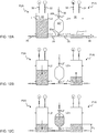
- Figs 11A-1 IE An embodiment of the calibration phase is further illustrated in Figs 11A-1 IE during relative calibration of one upstream pump P2A and one downstream pump P1A.
- Components intermediate the calibration chamber 30" and the pumps P1A, P2A have been omitted for clarity of presentation.
- the calibration chamber 30" is connected to the pumps P1A, P2A by a bypass line (cf. 25 in Fig. 1 ).
- white and black fill colours are used to differentiate between closed and open valves, respectively. It is understood that further valves may be installed to control the fluid flow to and from the calibration chamber 30", e.g. corresponding to valves 23, 45 in Fig. 1 .
- Fig. 11A illustrates the start of the calibration phase.
- Pump P2A is filled to upper level L2
- calibration chamber 30" is filled to level N
- pump P1A is filled to lower level L1.
- the level sensor in pump P1A indicates a height h L 1 with respect to an origin which may have any location, but coincides with the bottom of pump P1A in the examples given herein.
- the pumps P1A, P2A are then operated to transfer fluid from pump P2A to pump P1A, without changing the fluid level in the calibration chamber 30" ( Fig. 11B ), until the fluid level in pump P1A reaches the upper level L2 or the fluid level in pump P2A reaches the lower level L1, whichever occurs first.
- valves are switched such that the fluid flow from pump P2A is instead collected in the calibration chamber 30" until the fluid reaches the lower level L1 in pump P2A ( Fig. 11D ). If, on the other hand, the fluid level in pump P2A has reached the lower level L1, valves are switched such that the fluid is drawn from the calibration chamber 30" into pump P1A until the fluid reaches the upper level L2 in pump P1A (height h L 2 ). Thus, any difference in nominal stroke volume between the pumps P1A, P2A results in a level change in the calibration chamber 30".
- valves are switched (if necessary) such that pump P1A is operated to restore the fluid level at level N in the calibration chamber 30", resulting in height h 0 in pump P1A ( Fig. 11E ).
- the height h 0 represents the fluid level in pump P1A that balances the actual stroke volumes of the pumps P1A, P2A and may be denoted a "balancing level” or "balancing height”.
- V CAL volumetric difference between the pumps P1A, P2A forms a "calibration volume", denoted V CAL , which is computed based on the level change in the calibration chamber 30".
- the calibration volume V CAL is positive for an increased level in the chamber 30" and negative for a decreased level in the chamber 30". As shown in Fig.
- the pumps P1A, P2A are controlled to yield a desired UF rate when connected to the dialyzer 2, by adjusting the final upper fluid level in pump P1A to a height value h UF which is computed as a function of the calibration data ( h 0 , h L 2 , V CAL ) .
- ⁇ h is the level change in pump PI A corresponding to the calibration volume V CAL .
- one or more dedicated valves may be arranged in the bypass line to control of the flow of treatment solution into and out of the calibration cavity 30" during the calibration phase, similar to valve 45 in Fig. 4 .
- This valve may be closed at the start of the calibration phase and is only opened (together with air valve 32, if not already open) when the treatment solution reaches the lower level L1 in pump P2A and when the treatment solution reaches the upper level L2 in pump P1A, whichever occurs first.
- the calibration cavity 30" is selectively opened only to receive/deliver the calibration volume V CAL .
- the downstream and upstream pumps P1A, P2A are operated in sequence during the calibration phase.
- the inlet valve 35 of the downstream pump P1A may be closed during the emptying phase of the upstream pump P2A, while the valve 45 and the air valve 32 of the calibration cavity 30" are open, such that the treatment solution is pumped into the calibration cavity 30".
- the outlet valve 36 of the upstream pump P2A may be closed during the filling phase of the downstream pump P1A, while the valve 45 and the air valve 32 of the calibration cavity 30" are open, such that the treatment solution is drawn out of the calibration cavity 30" into the downstream pump P1A.
- This variant requires the volume of the calibration cavity 30" to be at least equal to the stroke volume of the upstream pump P2A.
- the calibration data may be obtained as an average over a number of calibration phases.
- the calibration phase includes a plurality of transfers of treatment solution from pump P2A to pump P1A, such that the volumetric difference for a plurality of transfers is accumulated in the calibration cavity 30", and that this accumulated volume is then finally transferred to pump P1A to yield an upper level therein.
- This variant may require the calibration cavity 30" to be larger, so as to accommodate the accumulated volumetric difference.
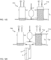
- Figs 12A-12G Such an embodiment is further illustrated in Figs 12A-12G .
- the system in Fig. 12 only differs from the system in Fig. 11 in that the calibration chamber 30" is designed to contain a large and well-defined volume of fluid between an upper reference level L2" and a lower reference level L1".
- the calibration chamber 30" is designed as a pipette. The majority of the volume contained within the calibration chamber 30" is defined within a central bulb portion, and the lower and upper levels L1", L2" are detected in a respective capillary tube portion 30a, 30b connected to the bulb portion.
- Fig. 12A illustrates the start of the calibration phase.
- Pump P2A is filled to its upper level L2, calibration chamber 30" is at its lower level L1", and pump P1A is filled to its lower level L1.
- the level sensor in pump P1A indicates a height h L 1 with respect to a predefined origin.
- the pumps P1A, P2A are then operated to pump fluid from pump P2A to pump P1A, without increasing the fluid level in the calibration chamber 30" ( Fig. 12B ).
- valves are switched to direct the fluid from pump P2A into the calibration chamber 30" instead of into pump P1A.
- the fluid remains at a first height h 1 in pump P1A while the calibration chamber 30" is being filled ( Fig. 12C ).
- This height h 1 is measured.
- valves are switched such that pump P1A draws the fluid from the calibration chamber 30" ( Fig. 12E ).
- a second height h 2 of the fluid level in pump P1A is measured ( Fig. 12F ) and valves are switched to establish communication between the pumps P1A and P2A, while closing off the calibration chamber 30", and to cause pump P1A to draw fluid from pump P2A until the fluid reaches the lower level in pump P2A.
- a balancing height h 0 in pump P1A is measured ( Fig. 12G ), and the calibration phase is completed.
- the level measurements in pump P1A during the calibration phase also makes it possible to determine the actual inlet flow of treatment solution to the dialyzer 2 with high accuracy.
- This inlet flow is given by the actual stroke volume of pump P2A, which is equal to the stroke volume V 0 of pump PI A when operated to reciprocate the interface I between heights h 0 and h L 1 :
- V 0 V CAL ⁇ h 0 ⁇ h L 1 / h 2 ⁇ h 1
- the desired UF rate is set by adjusting the stroke length of the downstream pump P1A, based on calibration data, while the upstream pump P2A is operated between its reference levels L1, L2.
- the desired UF rate is set by adjusting the stroke length of the upstream pump P2A while the downstream pump P1A is operated between its reference levels L1, L2.
- Such adjustment requires that the height values in the calibration data are measured in the upstream pump P2A during the calibration phase. This may be achieved by implementing a "reversed" calibration phase, which involves transferring fluid from the downstream pump P1A to the upstream pump P2A.
- the heights are determined in the upstream pump P2A and used for computing the final upper height h UF that yields the desired UF rate.
- the heights may be measured in the upstream pump P2A during the (non-reversed) calibration phase as shown in Figs 11-12 and used for calculating a height h UF of the final lower fluid level in pump P2A to yield the desired difference volume V UF .
- Equations (3) and (4) are applicable for computing h UF in such an embodiment if the balancing height h 0 and the level change ⁇ h are measured in pump P2A.
- the upstream module 7 ( Figs 1 and 3 ), and thus the upstream pumps P2A, P2B, to supply a constant flow of treatment solution to the dialyzer 2.
- the complexity of the upstream module 7 may increase if it needs to deliver momentarily changing flow rates of treatment solution, especially if the upstream module 7 is configured to prepare the treatment solution by mixing liquid concentrates with water. It may therefore be preferable to control the UF rate by adjusting the stroke length of the downstream pumps P1A, P1B.
- the desired UF rate is set by adjusting the final upper level in the downstream pumps P1A, P1B. It is realized that the desired UF rate may alternatively be set by adjusting the final lower level in the downstream pumps P1A, P1B, based on the calibration data.
- Fig. 5A illustrates an embodiment of an ultrasonic level detector 46 capable of continuous level detection.
- the level detector 46 is installed in a solution pump, but it may be equally applicable in the calibration cavity 30" and/or the concentration pumps.
- the level detector 46 is formed by an ultrasound transceiver which is arranged at the bottom of the cavity 30 to generate and detect ultrasonic waves in the cavity 30.
- the liquid level is determined, e.g. by the controller that operates the supply arrangement, based on the time difference (travelling time) between ultrasonic emission and receipt of an ultrasonic wave (echo) generated by reflection at the gas-liquid interface I.
- echo ultrasonic wave
- lugs 47A, 47B are formed in the wall of the cavity 30 to define reflection surfaces to the ultrasonic waves around a nominal top level (dashed line). As shown in Fig. 5B , the lugs 47A, 47B produce reference echoes R1, R2 in the output signal of the transceiver 46. Since the reference echoes R1, R2 correspond to fixed locations in the cavity 30, the location of the gas-liquid interface I may be precisely determined by relating the echo EI from the interface I to the reference echoes R1, R2. Assuming that the speed of sound is the same in the treatment solution between lugs 47A, 47B, the location of the interface I may be determined by interpolation, e.g.
- the controller may perform the determination of the reference echoes R1, R2 only intermittently during operation the supply arrangement, e.g. at startup or at regular intervals, and then determine the liquid level using the recorded time differences t R1 , t R2 , until the next determination of the reference echoes R1, R2.
- the liquid level needs to be raised above the upper lug 47B.
- the lugs 47A, 47B may have other placements in the cavity 30.
- the upper lug 47B may be located near, e.g. below, the upper level, L2
- the lower lug 47A lug may be located near, e.g. above, the lower level L1. More than two lugs may be provided in the cavity 30, and the above computations are readily extended to such an implementation.
- only one lug is formed on the wall of the cavity 30, preferably between the lower and upper levels L1, L2.
- controller implements any combination of the above-described uses of one and two reference echoes.
- Figs 6-8 illustrate the structure of a cassette 50 that integrates the downstream module 6, the upstream module 7 and the taration module 8 of Fig. 1 , as well as certain of the sensors/detectors.
- Figs 6B and 7B are perspective views taken from opposite directions of a body 52 of plastic material that defines a plurality of internal channels and cavities, and Figs 6A and 7A are corresponding exploded perspective views illustrating the body 52 before assembly.
- the body 52 defines a hydraulic manifold 53 in the form of internal liquid channels that distribute liquid (water, concentrates and treatment solution) to and between the cavities 30, 30', 30" of the modules 6-8 in Fig. 1 .
- the body 52 also defines a pneumatic manifold 54 in the form of internal pneumatic channels that distribute pneumatic pressure to the pumps P1A, P1B, P2A, P2B, P3A, P3B in the modules 6 and 7 in Fig. 1 .
- the body is formed by three rectangular plates 55A, 55B, 55C of solid plastic material which are sealingly assembled, e.g. by diffusion bonding, into a compact block in the shape of a cuboid, in this example a rectangular cuboid.
- the channels and cavities are formed by cooperating recesses in the faces of the plates 55A-55C, such that the partition planes between the plates 55A-55C intersects the respective channels and cavities.
- One pair of plates (55A and 55B) defines the hydraulic manifold 53 and part of the pneumatic manifold 54 (channels for positive pressure), and the other pair of plates (55B and 55C) defines the cavities 30, 30', 30" of the modules 6-8 and part of the pneumatic manifold 54 (channels for negative pressure).
- the separation of the hydraulic manifold 53 from the cavities 30, 30', 30" may facilitate design and manufacture. It may also facilitate optimization of the extent (length) of the hydraulic manifold 53 and the pressure drop in the hydraulic manifold 53.
- valve ports 56 for mounting of the air valves 32, inlet and outlet valves 35, 36, 38, 39, bypass valve 23, intermediate system valves 24A, 24B and valve 45 (collectively designed as a valve arrangement by reference number 58 in Figs 8A-8B ).
- all valves are 2-way solenoid valves that are normally closed. The choice of normally closed valves ensures that the valves are closed in the event of a power failure.
- the valves may be of any conceivable type, such as a top mounted valve with integrated valve seat which is mounted onto the valve port 56, a sub-top mounted valve that is mounted on top of a valve seat integrated in the valve port 56, or a cartridge valve which is inserted in one piece into the valve port 56.
- the body also includes a number of connectors providing fluid communication to the hydraulic manifold 53, including dialyzer connectors 60, 61 for connection to the dialyzer inlet and outlet, concentrate connectors 62, 63 for connection to the supplies for acid and base concentrates, a water connector 64 for connection to the water supply line 10, a waste connector 65 for connection to the third solution line 21C, and cell connectors 66, 67 for connection to the inlet and outlet of the conductivity cell 29.
- the body 52 also has pneumatic connectors 68, 69 in communication with pneumatic manifold 54 for connection to the positive and negative pressure sources.
- the body 52 in Figs 6-8 is also provided with holes 70, 71,72 for mounting the pressure sensors 22, 28 and the blood leak detector 29 in contact with the hydraulic manifold 53.
- Figs 9A-9B illustrate two embodiments of a cassette 50 with a hydraulic manifold that includes a dedicated cooling or heat dissipation channel 80 for diverting heat from the valves 58 and the body portion where the valves 58 are mounted.
- the cooling channel 80 may be connected in the water supply line 10, such that the heat from the valves 58 is used for pre-heating the incoming water.
- the cooling channel 80 extends around the valve mounting portion.
- the cooling channel 80 forms a meandering pattern across the mounting portion.
- Fig. 10 shows a schematic example of a dialysis machine or dialysis monitor 100 that includes a cassette 50 as described in the foregoing.
- a top cover 102 of the machine 100 has been removed to make the machine interior visible.
- the machine 100 has a controller 104 which is electrically connected to the cassette 50 to control the switching of the valve arrangement 58 and to retrieve data from various sensors/detectors in the machine, including the level detectors associated with the pump chambers and the calibration chamber.
- the controller 104 also performs the relative calibration of the solution pumps using the taration module 8 and sets the stroke lengths of the solution pumps accordingly to generate a desired UF rate in the dialyzer 2.
- the controller 104 may perform additional functions, e.g. operating a blood pump, and performing various safety functions, etc.
- the controller 104 may be implemented as a computer that executes dedicated program instructions. Positive and negative pressure sources 106, 108 are pneumatically connected to the cassette 50. Reservoirs 110, 112 for acid and base concentrate, respectively, are mounted on the machine 100 in fluid communication with the cassette 50. Water supply line 10 and waste line 21C are connected in fluid communication with the cassette 50. A dialyzer 2 is connected to dialysis lines 114, 116 that extend to the dialyzer connectors (60, 61 in Figs 8A-8B ) on the cassette 50. An extracorporeal blood flow circuit 118 is attached to the machine 100, such that a blood pump (not shown) in the machine 100 is operable to circulate blood from a patient, through the dialyzer 2 and back to the patient.
- the cassette may be installed to supply treatment solution in any type of dialysis system, including systems for hemodialysis, hemodiafiltration, hemofiltration, ultrafiltration (fluid removal), etc.
- the cassette may be configured to implement any combination of upstream, downstream and taration modules.
- the solution pumps need not be connected in parallel pairs, but a single solution pump may be used instead.
- more than two solution pumps may be connected in parallel in the upstream and/or downstream modules.
Landscapes
- Health & Medical Sciences (AREA)
- Heart & Thoracic Surgery (AREA)
- Engineering & Computer Science (AREA)
- Urology & Nephrology (AREA)
- Hematology (AREA)
- Vascular Medicine (AREA)
- Anesthesiology (AREA)
- Biomedical Technology (AREA)
- Life Sciences & Earth Sciences (AREA)
- Animal Behavior & Ethology (AREA)
- General Health & Medical Sciences (AREA)
- Public Health (AREA)
- Veterinary Medicine (AREA)
- Emergency Medicine (AREA)
- Mechanical Engineering (AREA)
- General Engineering & Computer Science (AREA)
- External Artificial Organs (AREA)
Claims (20)
- Kassette zum Pumpen einer Behandlungslösung durch einen Dialysator (2) in einem Dialysesystem, wobei die Kassette umfasst:einen Körper (52),einen hydraulischen Verteiler (53), der im Inneren des Körpers (52) definiert ist und für Fluidverbindung mit einem ersten hydraulischen Verbindungselement (60, 61) an dem Körper (52) gestaltet ist, wobei das erste hydraulische Verbindungselement (60, 61) dafür gestaltet ist, den Dialysator (2) mit der Kassette zu verbinden,einen pneumatischen Verteiler (54), der im Inneren des Körpers (52) definiert ist und für Fluidverbindung mit einem ersten pneumatischen Verbindungselement (68, 69) an dem Körper (52) gestaltet ist, wobei das erste pneumatische Verbindungselement (68, 69) dafür gestaltet ist, die Kassette mit einer pneumatischen Druckquelle (106, 108) zu verbinden,einen Satz von Lösungspumpen (P1A, P1B, P2A, P2B), die in die Kassette integriert sind und jeweils eine Pumpenkammer (30) umfassen, die im Inneren des Körpers (52) für Fluidverbindung mit dem hydraulischen und dem pneumatischen Verteiler (53, 54) definiert ist, undeine Ventilbaugruppe (58), die funktionsfähig ist, die Pumpenkammer (30) selektiv mit dem hydraulischen und dem pneumatischen Verteiler (53, 54) zu verbinden, um während des Betriebs der entsprechenden Lösungspumpe (P1A, P1B, P2A, P2B) eine Grenzfläche (I) in der Pumpenkammer (30) hin und her zu bewegen und dadurch die Behandlungslösung durch den hydraulischen Verteiler zu verschieben (53),wobei die Pumpenkammer (30) der entsprechenden Lösungspumpe (P1A, P1B, P2A, P2B) während des Betriebs der Lösungspumpe (P1A, P1B, P2A, P2B) die Grenzfläche (I) als direkte Gas-zu-Flüssigkeits-Grenzfläche (I) in der Pumpenkammer (30) zwischen einem über den pneumatischen Verteiler (54) zugeführten gasförmigen Stoff und der über den hydraulischen Verteiler (53) zugeführten Behandlungslösung definiert,wobei die Kassette ein stromaufwärtiges Teilsystem (7) zum Bereitstellen der Behandlungslösung an den Dialysator (2) über das erste hydraulische Verbindungselement (60) und ein stromabwärtiges Teilsystem (6) zum Pumpen der Behandlungslösung von dem Dialysator (2) über ein zweites hydraulisches Verbindungselement (61) an dem Körper (52) umfasst, wobei der Satz von Lösungspumpen eine stromaufwärtige Lösungspumpe (P2A, P2B) in dem stromaufwärtigen Teilsystem (7) und eine stromabwärtige Lösungspumpe (P1A, P1B) in dem stromabwärtigen Teilsystem (6) umfasst,und wobei die Kassette ferner ein Kalibrations-Teilsystem (8) zum relativen Kalibrieren der stromaufwärtigen Lösungspumpe (P2A, P2B) und der stromabwärtigen Lösungspumpe (P1A, P1B) umfasst, wobei das Kalibrations-Teilsystem (8) eine Kalibrierkammer (30") umfasst, die im Inneren des Körpers (52) definiert ist und für Fluidverbindung mit einer Bypassleitung (25) gestaltet ist, die zwischen den stromaufwärtigen und den stromabwärtigen Lösungspumpen (P2A, P2B; P1A, P1B) verläuft, wobei mit den stromaufwärtigen und den stromabwärtigen Lösungspumpen (P2A, P2B; P1A, P1B) Niveaudetektoren (46) verbunden sind, um die Niveaus der Behandlungslösung in der jeweiligen Pumpenkammer (30) anzuzeigen, wobei die Kassette funktionsfähig ist, die direkte Gas-zu-Flüssigkeits-Grenzfläche (I) zwischen einem oberen Niveau und einem unteren Niveau in der jeweiligen Pumpenkammer (30) hin und her zu bewegen, um die Behandlungslösung durch die Bypassleitung (25) zwischen den stromaufwärtigen und stromabwärtigen Lösungspumpen (P2A, P2B; P1A, P1B) zu pumpen, und wobei die Ventilbaugruppe (58) funktionsfähig ist, die Fluidverbindung zwischen der Bypassleitung (25) und der Kalibrierkammer (30") selektiv zu steuern,dadurch gekennzeichnet, dass die Kassette in einer Kalibrierphase arbeitsfähig ist, in der die Ventilbaugruppe (58) funktionsfähig ist: zu bewirken, dass eine von den stromaufwärtigen und stromabwärtigen Lösungspumpen (P2A, P2B; P1A, P1B) einen Entleerungshub durchführt, der die direkte Gas-zu-Flüssigkeits-Grenzfläche (I) von einem oberen Referenzniveau (L2) zu einem unteren Referenzniveau (L1) bewegt, um die Behandlungslösung in die Bypassleitung (25) zu drücken, zu bewirken, dass die andere von den stromaufwärtigen und stromabwärtigen Lösungspumpen (P2A, P2B; P1A, P1B) einen Füllhub durchführt, der die direkte Gas-zu-Flüssigkeits-Grenzfläche (I) von einem unteren Referenzniveau (L1) zu einem oberen Referenzniveau (L2) bewegt, um die Behandlungslösung aus der Bypassleitung (25) zu ziehen, und während der Entleerung- und Füllhübe selektiv Fluidverbindung zwischen der Bypassleitung (25) und der Kalibrierkammer (30") einzurichten, um ein bekanntes oder messbares Kalibriervolumen (VKAL) zwischen der Kalibrierkammer (30") und der Pumpenkammer (30) der stromaufwärtigen Lösungspumpe (P2A, P2B) oder der stromabwärtigen Lösungspumpe (P1A, P1B) zu überführen, wobei einer der Niveaudetektoren (46) funktionsfähig ist, die Niveauänderung (Δh), die dem Kalibriervolumen (VKAL) entspricht, in der Pumpenkammer (30) der stromaufwärtigen Lösungspumpe (P2A, P2B) oder der stromabwärtigen Lösungspumpe (P1A, P1B) zu messen.
- Kassette gemäß Anspruch 1, die mit einer Steuerung (104) verbunden ist, die an die Niveaudetektoren (46) gekoppelt ist und dafür gestaltet ist: während der Kalibrierphase ein Ausgleichsniveau (h0) in der Pumpenkammer (30) der stromaufwärtigen Lösungspumpe (P2A, P2B) oder der stromabwärtigen Lösungspumpe (P1A, P1B) zu bestimmen, so dass die Füll- und Entleerungshübe das gleiche Volumen aufweisen, wenn das Ausgleichsniveau (h0) das untere oder obere Referenzniveau (L1, L2) in der Pumpenkammer (30) ersetzt; und eine angepasste Hublänge für die direkte Gas-zu-Flüssigkeits-Grenzfläche (I) in der Pumpenkammer (30) der stromaufwärtigen Lösungspumpe (P2A, P2B) oder der stromabwärtigen Lösungspumpe (P1A, P1B) als Funktion der Niveauänderung (Δh), des Ausgleichsniveaus (h0) und des Kalibriervolumens (VKAL) zu bestimmen, um einen gegebenen Volumenunterschied (VUF) zwischen den stromaufwärtigen und stromabwärtigen Lösungspumpen (P2A, P2B; P1A, P1B) zu erzielen.
- Kassette gemäß Anspruch 2, wobei die Steuerung (104) dafür gestaltet ist, die angepasste Hublänge durch Einstellen eines der unteren und oberen Niveaus in der stromaufwärtigen Lösungspumpe (P2A, P2B) oder der stromabwärtigen Lösungspumpe (P1A, P1B) auf einen Abstand ΔhUF von dem Ausgleichsniveau (h0), ΔhUF = VUF/VKAL·Δh, zu bestimmen, wobei VUF der gegebene Volumenunterschied ist, VKAL das Kalibriervolumen ist und Δh die Niveauänderung ist.
- Kassette gemäß einem der Ansprüche 1-3, umfassend einen weiteren Niveaudetektor (46), der funktionsfähig ist, Niveaus der Behandlungslösung in der Kalibrierkammer (30") anzuzeigen, wobei die Ventilbaugruppe (58) in der Kalibrierphase funktionsfähig ist: während der Entleerung- und Füllhübe selektiv Fluidverbindung zwischen der Bypassleitung (25) und der Kalibrierkammer (30") einzurichten, um ein Anfangsniveau (N) der Behandlungslösung in der Kalibrierkammer (30") in Proportion zu dem Volumenunterschied zwischen dem Entleerungs- und dem Füllhub zu verändern, wobei der Volumenunterschied das Kalibriervolumen (VKAL) ist und durch den weiteren Niveaudetektor (46) messbar ist.
- Kassette gemäß einem der Ansprüche 1-4, wobei die Ventilbaugruppe (58) funktionsfähig ist, in der Kalibrierphase die Entleerung- und Füllhübe synchronisiert durchzuführen und selektiv Fluidverbindung zwischen der Bypassleitung (25) und der Kalibrierkammer (30") nur dann einzurichten, wenn die mit den Pumpenhohlräumen (30) verbundenen Niveaudetektoren (30) anzeigen, dass der Entleerungshub das untere Referenzniveau (L1) erreicht hat oder dass der Füllhub das obere Referenzniveau (L2) erreicht hat.
- Kassette gemäß einem der Ansprüche 1-5, umfassend einen weiteren Niveaudetektor (46), der funktionsfähig ist, Niveaus der Behandlungslösung in der Kalibrierkammer (30") anzuzeigen, wobei die Ventilbaugruppe (58) in der Kalibrierphase funktionsfähig ist: während der Entleerung- und Füllhübe selektiv Fluidverbindung zwischen der Bypassleitung (25) und der Kalibrierkammer (30") einzurichten, um die Behandlungslösung in die Kalibrierkammer (30") zu drücken, um das Niveau der Behandlungslösung in der Kalibrierkammer (30") von einem Anfangsniveau (L1") auf ein Endniveau (L2"), wie durch den weiteren Niveaudetektor (46) angezeigt, zu erhöhen und die Behandlungslösung aus der Kalibrierkammer (30") zu ziehen, um das Niveau der Behandlungslösung in der Kalibrierkammer (30") von dem Endniveau (L2") auf das Anfangsniveau (L1") zu senken, wobei die Kalibrierkammer (30") dafür gestaltet ist, das Kalibriervolumen (VKAL) zwischen dem Anfangs- und dem Endniveau (L1", L2") zu enthalten.
- Kassette gemäß einem der Ansprüche 1-6, wobei das stromaufwärtige Teilsystem (7) ferner dafür gestaltet ist, die Behandlungslösung durch Mischen von wenigstens zwei flüssigen Bestandteilen herzustellen, und wobei die Pumpenkammer (30) der stromaufwärtigen Lösungspumpe (P2A, P2B) wenigstens einen Einlass aufweist, der angeschlossen ist, um die flüssigen Bestandteile von dem hydraulischen Verteiler (53) zu erhalten, wobei Bewegung der direkten Gas-zu-Flüssigkeits-Grenzfläche (I) in der Pumpenkammer (30) bewirkt, dass die flüssigen Bestandteile durch den wenigstens einen Einlass eintreten und sich in der Pumpenkammer (30) mischen, um die Behandlungslösung zu bilden.
- Kassette gemäß Anspruch 7, wobei die flüssigen Bestandteile Wasser und ein Konzentrat umfassen und wobei das stromaufwärtige Teilsystem (7) ferner eine Konzentratpumpe (P3A, P3B) zum Zuführen des Konzentrats zu der stromaufwärtigen Lösungspumpe (P2A, P2B) umfasst, wobei die Konzentratpumpe (P3A, P3B) eine Dosierkammer (30') umfasst, der im Inneren des Körpers (52) definiert ist und mit dem hydraulischen und dem pneumatischen Verteiler (53, 54) verbunden ist, um eine direkte Gas-zu-Konzentrat-Grenzfläche (I) in der Dosierkammer (30') zu definieren, wobei die Ventilbaugruppe (58) funktionsfähig ist, selektiv die Dosierkammer (30') mit dem pneumatischen Verteiler (53) zu verbinden, um während des Betriebs der Konzentratpumpe (P3A, P3B) die direkte Gas-zu-Konzentrat-Grenzfläche (I) in der Dosierkammer (30') hin und her zu bewegen und dadurch Konzentrat aus dem hydraulischen Verteiler (53) durch einen Konzentrateinlass in die Dosierkammer (30') zu ziehen und das Konzentrat aus der Dosierkammer (30') durch einen Konzentratauslass in den hydraulischen Verteiler (53) zu verschieben, wobei der Konzentratauslass für Fluidverbindung mit der stromaufwärtigen Lösungspumpe (P2A, P2B) angeordnet ist.
- Kassette gemäß einem der vorstehenden Ansprüche, wobei die Ventilbaugruppe (58) funktionsfähig ist, bei einer Gasentfernungsphase während des Betriebs der Kassette die Pumpenkammer (30) von dem hydraulischen Verteiler (53) abzudichten und selektiv die Pumpenkammer (30) mit dem pneumatischen Verteiler (54) zu verbinden, um einen Unterdruck in der Pumpenkammer (30) einzurichten.
- Kassette gemäß einem der vorstehenden Ansprüche, wobei der Körper (52) eine Vielzahl von festen Platten (55A-55C) aus Kunststoffmaterial umfasst, die gemeinsam den hydraulischen Verteiler (53), den pneumatischen Verteiler (54) und die Pumpenkammer (30) jeder Lösungspumpe (P1A, P1B, P2A, P2B) definieren und die zusammengesetzt sind, um ein rechteckiges Kuboid zu bilden.
- Kassette gemäß einem der vorstehenden Ansprüche, wobei der Körper (52) eine Vielzahl von Ventilanschlüssen (56) an einer Außenoberfläche definiert, wobei jeder der Ventilanschlüsse (56) in Fluidverbindung mit entweder dem hydraulischen Verteiler (53) oder dem pneumatischen Verteiler (54) angeordnet ist, wobei die Ventilbaugruppe (58) eine Vielzahl von Ventilen (32, 35, 36, 38, 39, 45) umfasst, die in funktionsfähiger Verbindung mit den Ventilanschlüssen (56) an der Außenoberfläche des Körpers (52) angebracht sind, wobei die Ventile (32, 35, 36, 38, 39, 45) funktionsfähig sind, selektiv die Pumpenkammer (30) der entsprechenden Lösungspumpe (P1A, P1B, P2A, P2B) über die funktionsfähige Verbindung mit den Ventilanschlüssen (56) mit den hydraulischen und pneumatischen Verteilern (53, 54) zu verbinden.
- Kassette gemäß Anspruch 11, wobei der hydraulische Verteiler (53) einen speziellen Fluidweg (80) in dem Bereich der Ventilanschlüsse (56) umfasst, wobei der spezielle Fluidweg (80) dafür gestaltet ist, wenigstens einen Teil der von der Vielzahl von Ventilen (32, 35, 36, 38, 39, 45) emittierten Wärme zu der Behandlungslösung zu überführen, bevor die Behandlungslösung dem Dialysator (2) zugeführt wird.
- Kassette gemäß einem der vorstehenden Ansprüche, wobei jede Lösungspumpe (P1A, P1B, P2A, P2B) mit einem Ultraschallwandler (46) verbunden ist, der an einem Ende der Pumpenkammer (30) angeordnet ist, und wobei die Pumpenkammer (30) eine Reflektionsfläche (47A, 47B) in einem vorbestimmten Abstand von dem Ultraschallwandler (46) aufweist und wobei eine Steuerung (104) mit dem Ultraschallwandler (46) verbunden ist und funktionsfähig ist: eine Referenzlaufzeit für eine Schallwelle zu bestimmen, die von dem Ultraschallwandler (46) emittiert und von der Reflektionsfläche (47A, 47B) zu dem Ultraschallwandler (46) zurück reflektiert wird; eine aktuelle Laufzeit für eine Schallwelle zu bestimmen, die von dem Ultraschallwandler (46) emittiert und von der direkten Gas-zu-Flüssigkeits-Grenzfläche (I) zu dem Ultraschallwandler (46) zurück reflektiert wird; und den Ort der direkten Gas-zu-Flüssigkeits-Grenzfläche (I) in der Pumpenkammer (30) als Funktion der aktuellen Laufzeit, der Referenzlaufzeit und des vorbestimmten Abstands zu bestimmen.
- Kassette gemäß einem der vorstehenden Ansprüche, wobei jede Lösungspumpe (P1A, P1B, P2A, P2B) mit einem Ultraschallwandler (46) verbunden ist, der an einem Ende der Pumpenkammer (30) angeordnet ist, und wobei die Pumpenkammer (30) wenigstens zwei Reflektionsflächen (47A, 47B) in verschiedenen vorbestimmten Abständen von dem Ultraschallwandler (46) aufweist und wobei eine Steuerung (104) mit dem Ultraschallwandler (46) verbunden ist und funktionsfähig ist: eine jeweilige Referenzlaufzeit für eine Schallwelle zu bestimmen, die von dem Ultraschallwandler (46) emittiert und von den wenigstens zwei Reflektionsflächen (47A, 47B) zu dem Ultraschallwandler (46) zurück reflektiert wird; die mittlere Schallgeschwindigkeit in der Behandlungslösung im Inneren der Pumpenkammer (30) auf der Grundlage der jeweiligen Referenzlaufzeiten und der verschiedenen vorbestimmten Abstände zu bestimmen; eine aktuelle Laufzeit für eine Schallwelle zu bestimmen, die von dem Ultraschallwandler (46) emittiert und von der direkten Gas-zu-Flüssigkeits-Grenzfläche (I) zu dem Ultraschallwandler (46) zurück reflektiert wird; und den Ort der direkten Gas-zu-Flüssigkeits-Grenzfläche (I) in der Pumpenkammer (30) als Funktion der aktuellen Laufzeit und der mittleren Schallgeschwindigkeit zu bestimmen.
- Kassette gemäß einem der vorstehenden Ansprüche, wobei jede Lösungspumpe (P1A, P1B, P2A, P2B) mit einem Ultraschallwandler (46) verbunden ist, der an einem Ende der Pumpenkammer (30) angeordnet ist, und wobei die Pumpenkammer (30) wenigstens zwei Reflektionsflächen (47A, 47B) on verschiedenen vorbestimmten Abständen von dem Ultraschallwandler (46) aufweist und wobei eine Steuerung (104) mit dem Ultraschallwandler (46) verbunden ist und funktionsfähig ist: eine jeweilige Referenzlaufzeit für eine Schallwelle zu bestimmen, die von dem Ultraschallwandler (46) emittiert und von den wenigstens zwei Reflektionsflächen (47A, 47B) zu dem Ultraschallwandler (46) zurück reflektiert wird; die aktuelle Laufzeit für eine Schallwelle zu bestimmen, die von dem Ultraschallwandler (46) emittiert und von der direkten Gas-zu-Flüssigkeits-Grenzfläche (I) zu dem Ultraschallwandler (46) zurück reflektiert wird; und den Ort der direkten Gas-zu-Flüssigkeits-Grenzfläche (I) in der Pumpenkammer (30) durch Interpolation zwischen den verschiedenen vorbestimmten Abständen auf der Grundlage der Beziehung der aktuellen Laufzeit mit den entsprechenden Referenzlaufzeiten zu bestimmen.
- Kassette gemäß einem der vorstehenden Ansprüche, wobei jede Lösungspumpe (P1A, P1B, P2A, P2B) mit einem Ultraschallwandler (46) verbunden ist, der an einem Ende der Pumpenkammer (30) angeordnet ist, und wobei die Pumpenkammer (30) eine erste Reflektionsfläche (47B) aufweist, die näher an dem Ultraschallwandler (46) liegt als ein nominelles Niveau in der Pumpenkammer (30), und eine zweite Reflektionsfläche (47A), die von dem Ultraschallwandler (46) weiter entfernt ist als das nominelle Niveau.
- Kassette gemäß einem der vorstehenden Ansprüche, wobei der Satz von Lösungspumpen wenigstens zwei Lösungspumpen (P1A, P1B; P2A, P2B) umfasst, die parallel verbunden sind, und wobei die Ventilbaugruppe (58) funktionsfähig ist, die direkte Gas-zu-Flüssigkeit-Grenzfläche (I) in verschiedenen Phasen in die Pumpenhohlräume (30) der wenigstens zwei parallel verbundenen Lösungspumpen (P1A, P1B; P2A, P2B) zu treiben, um die Behandlungslösung alternierend aus der entsprechenden Pumpenkammer (30) zu pumpen.
- Kassette gemäß einem der vorstehenden Ansprüche, wobei das erste pneumatische Verbindungselement (68) zum Verbinden der Kassette mit einer pneumatischen Überdruckquelle (106) angeordnet ist und wobei der pneumatische Verteiler (54) ferner in Fluidverbindung mit einem zweiten pneumatischen Verbindungselement (69) an dem Körper (52) zum Verbinden der Kassette mit einer pneumatischen Unterdruckquelle (108) steht und wobei die Ventilbaugruppe (58) funktionsfähig ist, die Pumpenkammer (30) abwechselnd mit der pneumatischen Überdruckquelle (106) und der pneumatischen Unterdruckquelle (108) zu verbinden, um die direkte Gas-zu-Flüssigkeit-Grenzfläche (I) in der Pumpenkammer (30) hin und her zu bewegen.
- Dialysemonitor, umfassend die Kassette gemäß einem der vorstehenden Ansprüche und eine Steuerung (104) zum Steuern des Betriebs der Ventilbaugruppe (58).
- Verfahren zum Betreiben der Kassette gemäß Anspruch 14, umfassend: während der Kalibrierphase Bestimmen eines Ausgleichsniveaus (h0) in der Pumpenkammer (30) der stromaufwärtigen Lösungspumpe (P2A, P2B) oder der stromabwärtigen Lösungspumpe (P1A, P1B), so dass die Füll- und Entleerungshübe das gleiche Volumen aufweisen, wenn das Ausgleichsniveau (h0) das untere oder obere Referenzniveau (L1, L2) in der Pumpenkammer (30) ersetzt; und Bestimmen einer angepassten Hublänge für die direkte Gas-zu-Flüssigkeits-Grenzfläche (I) in der Pumpenkammer (30) der stromaufwärtigen Lösungspumpe (P2A, P2B) oder der stromabwärtigen Lösungspumpe (P1A, P1B) als Funktion der Niveauänderung (Δh), des Ausgleichsniveaus (h0) und des Kalibriervolumens (VKAL), um einen gegebenen Volumenunterschied (VUF) zwischen den stromaufwärtigen und den stromabwärtigen Lösungspumpen (P2A, P2B; P1A, P1B) zu erzielen.
Applications Claiming Priority (3)
| Application Number | Priority Date | Filing Date | Title |
|---|---|---|---|
| US201261736669P | 2012-12-13 | 2012-12-13 | |
| SE1251415 | 2012-12-13 | ||
| PCT/EP2013/075950 WO2014090746A1 (en) | 2012-12-13 | 2013-12-09 | Cassette for pumping a treatment solution through a dialyzer |
Publications (2)
| Publication Number | Publication Date |
|---|---|
| EP2931331A1 EP2931331A1 (de) | 2015-10-21 |
| EP2931331B1 true EP2931331B1 (de) | 2018-03-14 |
Family
ID=50776723
Family Applications (1)
| Application Number | Title | Priority Date | Filing Date |
|---|---|---|---|
| EP13815405.9A Active EP2931331B1 (de) | 2012-12-13 | 2013-12-09 | Kassette zum pumpen einer behandlungslösung durch einen dialysator |
Country Status (4)
| Country | Link |
|---|---|
| EP (1) | EP2931331B1 (de) |
| CN (2) | CN104302331B (de) |
| AU (1) | AU2013201553B1 (de) |
| WO (1) | WO2014090746A1 (de) |
Cited By (3)
| Publication number | Priority date | Publication date | Assignee | Title |
|---|---|---|---|---|
| EP3796954B1 (de) * | 2018-07-31 | 2023-05-03 | Fresenius Medical Care Holdings, Inc. | Drehventile für dialysesysteme |
| EP4189253A4 (de) * | 2020-07-31 | 2024-09-04 | Solidsvac Pty Ltd | Feststoffpumpe mit konstantem durchfluss |
| US12458737B2 (en) | 2021-05-11 | 2025-11-04 | Mozarc Medical Us Llc | Peritoneal dialysis cycler-cassette interface |
Families Citing this family (18)
| Publication number | Priority date | Publication date | Assignee | Title |
|---|---|---|---|---|
| WO2016037548A1 (zh) * | 2014-09-12 | 2016-03-17 | 昆山韦睿医疗科技有限公司 | 一种迷宫式耗材盒 |
| EP3539586B1 (de) * | 2014-10-10 | 2022-08-24 | NxStage Medical Inc. | Flussausgleichsverfahren |
| DE102015005179B4 (de) | 2015-04-22 | 2022-07-28 | Fresenius Medical Care Deutschland Gmbh | Dialysemaschine und Verfahren zum Betrieb eines Pneumatiksystems einer Dialysemaschine |
| EP3100749B1 (de) * | 2015-06-05 | 2018-11-07 | D_MED Consulting AG | Hämodialysegerät |
| WO2018017623A1 (en) | 2016-07-18 | 2018-01-25 | Nxstage Medical, Inc. | Flow balancing devices, methods, and systems |
| IT201800004949A1 (it) * | 2018-04-27 | 2019-10-27 | Collettore “manifold” per macchine e apparecchiature per dialisi e macchina o apparecchiatura per dialisi comprensiva del detto collettore | |
| CN113423456B (zh) | 2018-12-07 | 2024-03-19 | 费森尤斯医疗保健控股公司 | 用于管理医疗系统中的流体流动的旋转阀 |
| WO2020191156A1 (en) * | 2019-03-19 | 2020-09-24 | Deka Products Limited Partnership | Medical treatment systems, methods, and apparatuses using a plurality of fluid lines |
| WO2020237228A1 (en) | 2019-05-23 | 2020-11-26 | Nxstage Medical, Inc. | Flow synchronization devices, methods and systems |
| CN110118306B (zh) * | 2019-06-18 | 2024-04-02 | 泰通科技(广州)有限公司 | 一种模块式气路液路切换装置 |
| CN110193105A (zh) * | 2019-06-19 | 2019-09-03 | 余俐 | 自动腹膜透析设备 |
| US11654220B2 (en) * | 2019-06-20 | 2023-05-23 | Fresenius Medical Care Holdings, Inc. | Patient line check and occlusion detection for a dialysis machine using adjusted pump operating parameters |
| DE102019132178A1 (de) | 2019-11-27 | 2021-05-27 | B.Braun Avitum Ag | Ventilinsel für eine Hydraulikanordnung und Hydraulikanordnung mit Ventilinsel |
| CN118252992B (zh) * | 2021-08-18 | 2025-04-04 | 苏州才豪电子科技有限公司 | 多级调压式血液滤过装置 |
| CN216495097U (zh) * | 2021-09-30 | 2022-05-13 | 云鲸智能科技(东莞)有限公司 | 排水泵结构和清洁基站 |
| CN115492737B (zh) * | 2022-10-10 | 2025-08-01 | 杭州地之晶科技有限公司 | 介质输送系统 |
| CN120344279A (zh) * | 2023-03-02 | 2025-07-18 | 上海心光生物医药有限责任公司 | 透析设备的流道盒及便携式透析设备 |
| CN120227582A (zh) * | 2023-12-28 | 2025-07-01 | 丰凯利医疗器械(上海)有限公司 | 灌注装置及制造方法 |
Family Cites Families (10)
| Publication number | Priority date | Publication date | Assignee | Title |
|---|---|---|---|---|
| GB9321074D0 (en) * | 1993-10-13 | 1993-12-01 | British Nuclear Fuels Plc | Fluidic pumping system |
| GB0509330D0 (en) * | 2005-05-06 | 2005-06-15 | Imi Vision Ltd | Fluid processing apparatus |
| US20090230043A1 (en) * | 2005-05-06 | 2009-09-17 | Keith James Heyes | Fluid processing apparatus |
| US8357298B2 (en) * | 2007-02-27 | 2013-01-22 | Deka Products Limited Partnership | Hemodialysis systems and methods |
| US8366655B2 (en) * | 2007-02-27 | 2013-02-05 | Deka Products Limited Partnership | Peritoneal dialysis sensor apparatus systems, devices and methods |
| US7736328B2 (en) * | 2007-07-05 | 2010-06-15 | Baxter International Inc. | Dialysis system having supply container autoconnection |
| DE102008038097A1 (de) * | 2008-08-18 | 2010-02-25 | Fresenius Medical Care Deutschland Gmbh | Kassette zur Förderung von Flüssigkeiten, insbesondere Dialyseflüssigkeiten |
| WO2011038858A1 (de) * | 2009-09-29 | 2011-04-07 | Fresenius Medical Care Deutschland Gmbh | Vorrichtung zur dialysebehandlung und verfahren zum bilanzieren von frischer und verbrauchter dialysierflüssigkeit |
| US9707563B2 (en) * | 2010-05-04 | 2017-07-18 | Agency For Science, Technology And Research | Reagent fluid dispensing device, and method of dispensing a reagent fluid |
| DE102011016869A1 (de) * | 2011-04-13 | 2012-10-18 | Fresenius Medical Care Deutschland Gmbh | Vorrichtung und Verfahren zum Fördern von einer Flüssigkeit zu einer Filtereinheit einer medizinischen Behandlungsvorrichtung |
-
2013
- 2013-03-15 AU AU2013201553A patent/AU2013201553B1/en active Active
- 2013-12-09 WO PCT/EP2013/075950 patent/WO2014090746A1/en not_active Ceased
- 2013-12-09 EP EP13815405.9A patent/EP2931331B1/de active Active
- 2013-12-09 CN CN201380025246.8A patent/CN104302331B/zh active Active
- 2013-12-09 CN CN201610329572.3A patent/CN106039444B/zh active Active
Cited By (3)
| Publication number | Priority date | Publication date | Assignee | Title |
|---|---|---|---|---|
| EP3796954B1 (de) * | 2018-07-31 | 2023-05-03 | Fresenius Medical Care Holdings, Inc. | Drehventile für dialysesysteme |
| EP4189253A4 (de) * | 2020-07-31 | 2024-09-04 | Solidsvac Pty Ltd | Feststoffpumpe mit konstantem durchfluss |
| US12458737B2 (en) | 2021-05-11 | 2025-11-04 | Mozarc Medical Us Llc | Peritoneal dialysis cycler-cassette interface |
Also Published As
| Publication number | Publication date |
|---|---|
| AU2013201553B1 (en) | 2014-05-29 |
| CN104302331B (zh) | 2016-06-01 |
| CN106039444A (zh) | 2016-10-26 |
| EP2931331A1 (de) | 2015-10-21 |
| WO2014090746A1 (en) | 2014-06-19 |
| CN106039444B (zh) | 2019-01-01 |
| CN104302331A (zh) | 2015-01-21 |
Similar Documents
| Publication | Publication Date | Title |
|---|---|---|
| EP2931331B1 (de) | Kassette zum pumpen einer behandlungslösung durch einen dialysator | |
| US9623165B2 (en) | Cassette for pumping a treatment solution through a dialyzer | |
| JP6337037B2 (ja) | プライミング、適用量およびリンスバックを備える透析システム | |
| CA3057806C (en) | System and method for conducting hemodialysis and hemofiltration | |
| EP2442845B1 (de) | Dialysemaschine | |
| EP2612684B1 (de) | Dialysemaschine mit ausgeglichenem Fluss | |
| EP2334412B1 (de) | Entlüftungssystem und -verfahren für dialysesysteme | |
| US9962476B2 (en) | Individual pump calibration for ultrafiltration control in a dialysis apparatus | |
| JP2007510473A5 (de) |
Legal Events
| Date | Code | Title | Description |
|---|---|---|---|
| PUAI | Public reference made under article 153(3) epc to a published international application that has entered the european phase |
Free format text: ORIGINAL CODE: 0009012 |
|
| 17P | Request for examination filed |
Effective date: 20150713 |
|
| AK | Designated contracting states |
Kind code of ref document: A1 Designated state(s): AL AT BE BG CH CY CZ DE DK EE ES FI FR GB GR HR HU IE IS IT LI LT LU LV MC MK MT NL NO PL PT RO RS SE SI SK SM TR |
|
| AX | Request for extension of the european patent |
Extension state: BA ME |
|
| DAX | Request for extension of the european patent (deleted) | ||
| 17Q | First examination report despatched |
Effective date: 20160506 |
|
| GRAP | Despatch of communication of intention to grant a patent |
Free format text: ORIGINAL CODE: EPIDOSNIGR1 |
|
| INTG | Intention to grant announced |
Effective date: 20171005 |
|
| RIN1 | Information on inventor provided before grant (corrected) |
Inventor name: PERSSON, ANTON Inventor name: JANSSON, OLOF Inventor name: HOBRO, STURE Inventor name: JOENSSON, LENNART |
|
| GRAS | Grant fee paid |
Free format text: ORIGINAL CODE: EPIDOSNIGR3 |
|
| GRAA | (expected) grant |
Free format text: ORIGINAL CODE: 0009210 |
|
| AK | Designated contracting states |
Kind code of ref document: B1 Designated state(s): AL AT BE BG CH CY CZ DE DK EE ES FI FR GB GR HR HU IE IS IT LI LT LU LV MC MK MT NL NO PL PT RO RS SE SI SK SM TR |
|
| REG | Reference to a national code |
Ref country code: GB Ref legal event code: FG4D |
|
| REG | Reference to a national code |
Ref country code: CH Ref legal event code: EP Ref country code: AT Ref legal event code: REF Ref document number: 978231 Country of ref document: AT Kind code of ref document: T Effective date: 20180315 |
|
| REG | Reference to a national code |
Ref country code: IE Ref legal event code: FG4D |
|
| REG | Reference to a national code |
Ref country code: DE Ref legal event code: R096 Ref document number: 602013034486 Country of ref document: DE |
|
| REG | Reference to a national code |
Ref country code: NL Ref legal event code: MP Effective date: 20180314 |
|
| REG | Reference to a national code |
Ref country code: LT Ref legal event code: MG4D |
|
| PG25 | Lapsed in a contracting state [announced via postgrant information from national office to epo] |
Ref country code: LT Free format text: LAPSE BECAUSE OF FAILURE TO SUBMIT A TRANSLATION OF THE DESCRIPTION OR TO PAY THE FEE WITHIN THE PRESCRIBED TIME-LIMIT Effective date: 20180314 Ref country code: NO Free format text: LAPSE BECAUSE OF FAILURE TO SUBMIT A TRANSLATION OF THE DESCRIPTION OR TO PAY THE FEE WITHIN THE PRESCRIBED TIME-LIMIT Effective date: 20180614 Ref country code: HR Free format text: LAPSE BECAUSE OF FAILURE TO SUBMIT A TRANSLATION OF THE DESCRIPTION OR TO PAY THE FEE WITHIN THE PRESCRIBED TIME-LIMIT Effective date: 20180314 Ref country code: FI Free format text: LAPSE BECAUSE OF FAILURE TO SUBMIT A TRANSLATION OF THE DESCRIPTION OR TO PAY THE FEE WITHIN THE PRESCRIBED TIME-LIMIT Effective date: 20180314 Ref country code: CY Free format text: LAPSE BECAUSE OF FAILURE TO SUBMIT A TRANSLATION OF THE DESCRIPTION OR TO PAY THE FEE WITHIN THE PRESCRIBED TIME-LIMIT Effective date: 20180314 |
|
| REG | Reference to a national code |
Ref country code: AT Ref legal event code: MK05 Ref document number: 978231 Country of ref document: AT Kind code of ref document: T Effective date: 20180314 |
|
| PG25 | Lapsed in a contracting state [announced via postgrant information from national office to epo] |
Ref country code: LV Free format text: LAPSE BECAUSE OF FAILURE TO SUBMIT A TRANSLATION OF THE DESCRIPTION OR TO PAY THE FEE WITHIN THE PRESCRIBED TIME-LIMIT Effective date: 20180314 Ref country code: SE Free format text: LAPSE BECAUSE OF FAILURE TO SUBMIT A TRANSLATION OF THE DESCRIPTION OR TO PAY THE FEE WITHIN THE PRESCRIBED TIME-LIMIT Effective date: 20180314 Ref country code: GR Free format text: LAPSE BECAUSE OF FAILURE TO SUBMIT A TRANSLATION OF THE DESCRIPTION OR TO PAY THE FEE WITHIN THE PRESCRIBED TIME-LIMIT Effective date: 20180615 Ref country code: BG Free format text: LAPSE BECAUSE OF FAILURE TO SUBMIT A TRANSLATION OF THE DESCRIPTION OR TO PAY THE FEE WITHIN THE PRESCRIBED TIME-LIMIT Effective date: 20180614 Ref country code: RS Free format text: LAPSE BECAUSE OF FAILURE TO SUBMIT A TRANSLATION OF THE DESCRIPTION OR TO PAY THE FEE WITHIN THE PRESCRIBED TIME-LIMIT Effective date: 20180314 |
|
| PG25 | Lapsed in a contracting state [announced via postgrant information from national office to epo] |
Ref country code: IT Free format text: LAPSE BECAUSE OF FAILURE TO SUBMIT A TRANSLATION OF THE DESCRIPTION OR TO PAY THE FEE WITHIN THE PRESCRIBED TIME-LIMIT Effective date: 20180314 Ref country code: AL Free format text: LAPSE BECAUSE OF FAILURE TO SUBMIT A TRANSLATION OF THE DESCRIPTION OR TO PAY THE FEE WITHIN THE PRESCRIBED TIME-LIMIT Effective date: 20180314 Ref country code: PL Free format text: LAPSE BECAUSE OF FAILURE TO SUBMIT A TRANSLATION OF THE DESCRIPTION OR TO PAY THE FEE WITHIN THE PRESCRIBED TIME-LIMIT Effective date: 20180314 Ref country code: EE Free format text: LAPSE BECAUSE OF FAILURE TO SUBMIT A TRANSLATION OF THE DESCRIPTION OR TO PAY THE FEE WITHIN THE PRESCRIBED TIME-LIMIT Effective date: 20180314 Ref country code: RO Free format text: LAPSE BECAUSE OF FAILURE TO SUBMIT A TRANSLATION OF THE DESCRIPTION OR TO PAY THE FEE WITHIN THE PRESCRIBED TIME-LIMIT Effective date: 20180314 Ref country code: ES Free format text: LAPSE BECAUSE OF FAILURE TO SUBMIT A TRANSLATION OF THE DESCRIPTION OR TO PAY THE FEE WITHIN THE PRESCRIBED TIME-LIMIT Effective date: 20180314 Ref country code: NL Free format text: LAPSE BECAUSE OF FAILURE TO SUBMIT A TRANSLATION OF THE DESCRIPTION OR TO PAY THE FEE WITHIN THE PRESCRIBED TIME-LIMIT Effective date: 20180314 |
|
| PG25 | Lapsed in a contracting state [announced via postgrant information from national office to epo] |
Ref country code: SM Free format text: LAPSE BECAUSE OF FAILURE TO SUBMIT A TRANSLATION OF THE DESCRIPTION OR TO PAY THE FEE WITHIN THE PRESCRIBED TIME-LIMIT Effective date: 20180314 Ref country code: CZ Free format text: LAPSE BECAUSE OF FAILURE TO SUBMIT A TRANSLATION OF THE DESCRIPTION OR TO PAY THE FEE WITHIN THE PRESCRIBED TIME-LIMIT Effective date: 20180314 Ref country code: AT Free format text: LAPSE BECAUSE OF FAILURE TO SUBMIT A TRANSLATION OF THE DESCRIPTION OR TO PAY THE FEE WITHIN THE PRESCRIBED TIME-LIMIT Effective date: 20180314 Ref country code: SK Free format text: LAPSE BECAUSE OF FAILURE TO SUBMIT A TRANSLATION OF THE DESCRIPTION OR TO PAY THE FEE WITHIN THE PRESCRIBED TIME-LIMIT Effective date: 20180314 |
|
| REG | Reference to a national code |
Ref country code: DE Ref legal event code: R097 Ref document number: 602013034486 Country of ref document: DE |
|
| PG25 | Lapsed in a contracting state [announced via postgrant information from national office to epo] |
Ref country code: PT Free format text: LAPSE BECAUSE OF FAILURE TO SUBMIT A TRANSLATION OF THE DESCRIPTION OR TO PAY THE FEE WITHIN THE PRESCRIBED TIME-LIMIT Effective date: 20180716 |
|
| PLBE | No opposition filed within time limit |
Free format text: ORIGINAL CODE: 0009261 |
|
| STAA | Information on the status of an ep patent application or granted ep patent |
Free format text: STATUS: NO OPPOSITION FILED WITHIN TIME LIMIT |
|
| PG25 | Lapsed in a contracting state [announced via postgrant information from national office to epo] |
Ref country code: DK Free format text: LAPSE BECAUSE OF FAILURE TO SUBMIT A TRANSLATION OF THE DESCRIPTION OR TO PAY THE FEE WITHIN THE PRESCRIBED TIME-LIMIT Effective date: 20180314 |
|
| 26N | No opposition filed |
Effective date: 20181217 |
|
| PG25 | Lapsed in a contracting state [announced via postgrant information from national office to epo] |
Ref country code: SI Free format text: LAPSE BECAUSE OF FAILURE TO SUBMIT A TRANSLATION OF THE DESCRIPTION OR TO PAY THE FEE WITHIN THE PRESCRIBED TIME-LIMIT Effective date: 20180314 |
|
| REG | Reference to a national code |
Ref country code: DE Ref legal event code: R119 Ref document number: 602013034486 Country of ref document: DE |
|
| REG | Reference to a national code |
Ref country code: CH Ref legal event code: PL |
|
| PG25 | Lapsed in a contracting state [announced via postgrant information from national office to epo] |
Ref country code: MC Free format text: LAPSE BECAUSE OF FAILURE TO SUBMIT A TRANSLATION OF THE DESCRIPTION OR TO PAY THE FEE WITHIN THE PRESCRIBED TIME-LIMIT Effective date: 20180314 Ref country code: LU Free format text: LAPSE BECAUSE OF NON-PAYMENT OF DUE FEES Effective date: 20181209 |
|
| REG | Reference to a national code |
Ref country code: IE Ref legal event code: MM4A |
|
| REG | Reference to a national code |
Ref country code: BE Ref legal event code: MM Effective date: 20181231 |
|
| PG25 | Lapsed in a contracting state [announced via postgrant information from national office to epo] |
Ref country code: DE Free format text: LAPSE BECAUSE OF NON-PAYMENT OF DUE FEES Effective date: 20190702 Ref country code: IE Free format text: LAPSE BECAUSE OF NON-PAYMENT OF DUE FEES Effective date: 20181209 |
|
| PG25 | Lapsed in a contracting state [announced via postgrant information from national office to epo] |
Ref country code: BE Free format text: LAPSE BECAUSE OF NON-PAYMENT OF DUE FEES Effective date: 20181231 |
|
| PG25 | Lapsed in a contracting state [announced via postgrant information from national office to epo] |
Ref country code: LI Free format text: LAPSE BECAUSE OF NON-PAYMENT OF DUE FEES Effective date: 20181231 Ref country code: CH Free format text: LAPSE BECAUSE OF NON-PAYMENT OF DUE FEES Effective date: 20181231 |
|
| PG25 | Lapsed in a contracting state [announced via postgrant information from national office to epo] |
Ref country code: MT Free format text: LAPSE BECAUSE OF NON-PAYMENT OF DUE FEES Effective date: 20181209 |
|
| PG25 | Lapsed in a contracting state [announced via postgrant information from national office to epo] |
Ref country code: TR Free format text: LAPSE BECAUSE OF FAILURE TO SUBMIT A TRANSLATION OF THE DESCRIPTION OR TO PAY THE FEE WITHIN THE PRESCRIBED TIME-LIMIT Effective date: 20180314 |
|
| PG25 | Lapsed in a contracting state [announced via postgrant information from national office to epo] |
Ref country code: MK Free format text: LAPSE BECAUSE OF NON-PAYMENT OF DUE FEES Effective date: 20180314 Ref country code: HU Free format text: LAPSE BECAUSE OF FAILURE TO SUBMIT A TRANSLATION OF THE DESCRIPTION OR TO PAY THE FEE WITHIN THE PRESCRIBED TIME-LIMIT; INVALID AB INITIO Effective date: 20131209 |
|
| PG25 | Lapsed in a contracting state [announced via postgrant information from national office to epo] |
Ref country code: IS Free format text: LAPSE BECAUSE OF FAILURE TO SUBMIT A TRANSLATION OF THE DESCRIPTION OR TO PAY THE FEE WITHIN THE PRESCRIBED TIME-LIMIT Effective date: 20180714 |
|
| PGFP | Annual fee paid to national office [announced via postgrant information from national office to epo] |
Ref country code: GB Payment date: 20251120 Year of fee payment: 13 |
|
| PGFP | Annual fee paid to national office [announced via postgrant information from national office to epo] |
Ref country code: FR Payment date: 20251119 Year of fee payment: 13 |