EP2932080B1 - Integrierte abgasmanagementvorrichtung - Google Patents
Integrierte abgasmanagementvorrichtung Download PDFInfo
- Publication number
- EP2932080B1 EP2932080B1 EP13802634.9A EP13802634A EP2932080B1 EP 2932080 B1 EP2932080 B1 EP 2932080B1 EP 13802634 A EP13802634 A EP 13802634A EP 2932080 B1 EP2932080 B1 EP 2932080B1
- Authority
- EP
- European Patent Office
- Prior art keywords
- inlet
- outlet
- segment
- exhaust pipe
- chamber
- Prior art date
- Legal status (The legal status is an assumption and is not a legal conclusion. Google has not performed a legal analysis and makes no representation as to the accuracy of the status listed.)
- Not-in-force
Links
Images

Classifications
-
- F—MECHANICAL ENGINEERING; LIGHTING; HEATING; WEAPONS; BLASTING
- F02—COMBUSTION ENGINES; HOT-GAS OR COMBUSTION-PRODUCT ENGINE PLANTS
- F02M—SUPPLYING COMBUSTION ENGINES IN GENERAL WITH COMBUSTIBLE MIXTURES OR CONSTITUENTS THEREOF
- F02M26/00—Engine-pertinent apparatus for adding exhaust gases to combustion-air, main fuel or fuel-air mixture, e.g. by exhaust gas recirculation [EGR] systems
- F02M26/13—Arrangement or layout of EGR passages, e.g. in relation to specific engine parts or for incorporation of accessories
- F02M26/14—Arrangement or layout of EGR passages, e.g. in relation to specific engine parts or for incorporation of accessories in relation to the exhaust system
- F02M26/15—Arrangement or layout of EGR passages, e.g. in relation to specific engine parts or for incorporation of accessories in relation to the exhaust system in relation to engine exhaust purifying apparatus
-
- F—MECHANICAL ENGINEERING; LIGHTING; HEATING; WEAPONS; BLASTING
- F02—COMBUSTION ENGINES; HOT-GAS OR COMBUSTION-PRODUCT ENGINE PLANTS
- F02M—SUPPLYING COMBUSTION ENGINES IN GENERAL WITH COMBUSTIBLE MIXTURES OR CONSTITUENTS THEREOF
- F02M26/00—Engine-pertinent apparatus for adding exhaust gases to combustion-air, main fuel or fuel-air mixture, e.g. by exhaust gas recirculation [EGR] systems
- F02M26/13—Arrangement or layout of EGR passages, e.g. in relation to specific engine parts or for incorporation of accessories
- F02M26/22—Arrangement or layout of EGR passages, e.g. in relation to specific engine parts or for incorporation of accessories with coolers in the recirculation passage
- F02M26/29—Constructional details of the coolers, e.g. pipes, plates, ribs, insulation or materials
-
- F—MECHANICAL ENGINEERING; LIGHTING; HEATING; WEAPONS; BLASTING
- F28—HEAT EXCHANGE IN GENERAL
- F28D—HEAT-EXCHANGE APPARATUS, NOT PROVIDED FOR IN ANOTHER SUBCLASS, IN WHICH THE HEAT-EXCHANGE MEDIA DO NOT COME INTO DIRECT CONTACT
- F28D21/00—Heat-exchange apparatus not covered by any of the groups F28D1/00 - F28D20/00
- F28D21/0001—Recuperative heat exchangers
- F28D21/0003—Recuperative heat exchangers the heat being recuperated from exhaust gases
-
- F—MECHANICAL ENGINEERING; LIGHTING; HEATING; WEAPONS; BLASTING
- F28—HEAT EXCHANGE IN GENERAL
- F28D—HEAT-EXCHANGE APPARATUS, NOT PROVIDED FOR IN ANOTHER SUBCLASS, IN WHICH THE HEAT-EXCHANGE MEDIA DO NOT COME INTO DIRECT CONTACT
- F28D7/00—Heat-exchange apparatus having stationary tubular conduit assemblies for both heat-exchange media, the media being in contact with different sides of a conduit wall
- F28D7/16—Heat-exchange apparatus having stationary tubular conduit assemblies for both heat-exchange media, the media being in contact with different sides of a conduit wall the conduits being arranged in parallel spaced relation
-
- F—MECHANICAL ENGINEERING; LIGHTING; HEATING; WEAPONS; BLASTING
- F01—MACHINES OR ENGINES IN GENERAL; ENGINE PLANTS IN GENERAL; STEAM ENGINES
- F01N—GAS-FLOW SILENCERS OR EXHAUST APPARATUS FOR MACHINES OR ENGINES IN GENERAL; GAS-FLOW SILENCERS OR EXHAUST APPARATUS FOR INTERNAL-COMBUSTION ENGINES
- F01N13/00—Exhaust or silencing apparatus characterised by constructional features
- F01N13/18—Construction facilitating manufacture, assembly, or disassembly
- F01N13/1805—Fixing exhaust manifolds, exhaust pipes or pipe sections to each other, to engine or to vehicle body
- F01N13/1811—Fixing exhaust manifolds, exhaust pipes or pipe sections to each other, to engine or to vehicle body with means permitting relative movement, e.g. compensation of thermal expansion or vibration
- F01N13/1816—Fixing exhaust manifolds, exhaust pipes or pipe sections to each other, to engine or to vehicle body with means permitting relative movement, e.g. compensation of thermal expansion or vibration the pipe sections being joined together by flexible tubular elements only, e.g. using bellows or strip-wound pipes
-
- F—MECHANICAL ENGINEERING; LIGHTING; HEATING; WEAPONS; BLASTING
- F01—MACHINES OR ENGINES IN GENERAL; ENGINE PLANTS IN GENERAL; STEAM ENGINES
- F01N—GAS-FLOW SILENCERS OR EXHAUST APPARATUS FOR MACHINES OR ENGINES IN GENERAL; GAS-FLOW SILENCERS OR EXHAUST APPARATUS FOR INTERNAL-COMBUSTION ENGINES
- F01N3/00—Exhaust or silencing apparatus having means for purifying, rendering innocuous, or otherwise treating exhaust
- F01N3/02—Exhaust or silencing apparatus having means for purifying, rendering innocuous, or otherwise treating exhaust for cooling, or for removing solid constituents of, exhaust
- F01N3/021—Exhaust or silencing apparatus having means for purifying, rendering innocuous, or otherwise treating exhaust for cooling, or for removing solid constituents of, exhaust by means of filters
-
- F—MECHANICAL ENGINEERING; LIGHTING; HEATING; WEAPONS; BLASTING
- F01—MACHINES OR ENGINES IN GENERAL; ENGINE PLANTS IN GENERAL; STEAM ENGINES
- F01N—GAS-FLOW SILENCERS OR EXHAUST APPARATUS FOR MACHINES OR ENGINES IN GENERAL; GAS-FLOW SILENCERS OR EXHAUST APPARATUS FOR INTERNAL-COMBUSTION ENGINES
- F01N3/00—Exhaust or silencing apparatus having means for purifying, rendering innocuous, or otherwise treating exhaust
- F01N3/08—Exhaust or silencing apparatus having means for purifying, rendering innocuous, or otherwise treating exhaust for rendering innocuous
- F01N3/10—Exhaust or silencing apparatus having means for purifying, rendering innocuous, or otherwise treating exhaust for rendering innocuous by thermal or catalytic conversion of noxious components of exhaust
- F01N3/24—Exhaust or silencing apparatus having means for purifying, rendering innocuous, or otherwise treating exhaust for rendering innocuous by thermal or catalytic conversion of noxious components of exhaust characterised by constructional aspects of converting apparatus
- F01N3/28—Construction of catalytic reactors
-
- F—MECHANICAL ENGINEERING; LIGHTING; HEATING; WEAPONS; BLASTING
- F02—COMBUSTION ENGINES; HOT-GAS OR COMBUSTION-PRODUCT ENGINE PLANTS
- F02M—SUPPLYING COMBUSTION ENGINES IN GENERAL WITH COMBUSTIBLE MIXTURES OR CONSTITUENTS THEREOF
- F02M26/00—Engine-pertinent apparatus for adding exhaust gases to combustion-air, main fuel or fuel-air mixture, e.g. by exhaust gas recirculation [EGR] systems
- F02M26/13—Arrangement or layout of EGR passages, e.g. in relation to specific engine parts or for incorporation of accessories
- F02M26/14—Arrangement or layout of EGR passages, e.g. in relation to specific engine parts or for incorporation of accessories in relation to the exhaust system
- F02M26/16—Arrangement or layout of EGR passages, e.g. in relation to specific engine parts or for incorporation of accessories in relation to the exhaust system with EGR valves located at or near the connection to the exhaust system
-
- F—MECHANICAL ENGINEERING; LIGHTING; HEATING; WEAPONS; BLASTING
- F02—COMBUSTION ENGINES; HOT-GAS OR COMBUSTION-PRODUCT ENGINE PLANTS
- F02M—SUPPLYING COMBUSTION ENGINES IN GENERAL WITH COMBUSTIBLE MIXTURES OR CONSTITUENTS THEREOF
- F02M26/00—Engine-pertinent apparatus for adding exhaust gases to combustion-air, main fuel or fuel-air mixture, e.g. by exhaust gas recirculation [EGR] systems
- F02M26/13—Arrangement or layout of EGR passages, e.g. in relation to specific engine parts or for incorporation of accessories
- F02M26/22—Arrangement or layout of EGR passages, e.g. in relation to specific engine parts or for incorporation of accessories with coolers in the recirculation passage
- F02M26/23—Layout, e.g. schematics
- F02M26/25—Layout, e.g. schematics with coolers having bypasses
-
- F—MECHANICAL ENGINEERING; LIGHTING; HEATING; WEAPONS; BLASTING
- F02—COMBUSTION ENGINES; HOT-GAS OR COMBUSTION-PRODUCT ENGINE PLANTS
- F02M—SUPPLYING COMBUSTION ENGINES IN GENERAL WITH COMBUSTIBLE MIXTURES OR CONSTITUENTS THEREOF
- F02M26/00—Engine-pertinent apparatus for adding exhaust gases to combustion-air, main fuel or fuel-air mixture, e.g. by exhaust gas recirculation [EGR] systems
- F02M26/13—Arrangement or layout of EGR passages, e.g. in relation to specific engine parts or for incorporation of accessories
- F02M26/22—Arrangement or layout of EGR passages, e.g. in relation to specific engine parts or for incorporation of accessories with coolers in the recirculation passage
- F02M26/29—Constructional details of the coolers, e.g. pipes, plates, ribs, insulation or materials
- F02M26/32—Liquid-cooled heat exchangers
-
- F—MECHANICAL ENGINEERING; LIGHTING; HEATING; WEAPONS; BLASTING
- F28—HEAT EXCHANGE IN GENERAL
- F28F—DETAILS OF HEAT-EXCHANGE AND HEAT-TRANSFER APPARATUS, OF GENERAL APPLICATION
- F28F27/00—Control arrangements or safety devices specially adapted for heat-exchange or heat-transfer apparatus
- F28F27/02—Control arrangements or safety devices specially adapted for heat-exchange or heat-transfer apparatus for controlling the distribution of heat-exchange media between different channels
Definitions
- the present invention relates to a gas management device suitable for being installed at the outlet of a particle filter or of a catalytic converter.
- This device is characterized by a very compact configuration having at least the heat exchanger for an EGR (Exhaust Gas Recirculation) system, particularly suitable for a low pressure system, and an exhaust gas discharge pipe which is part of the exhaust line.
- EGR exhaust Gas Recirculation
- the device also allows integrating a bypass valve for the EGR heat exchanger.
- the device allows integrating a heat recovery unit participating in the EGR system.
- the device also allows both including a bypass and including a heat recovery unit. The degree of integration with the particle filter of the catalytic converter is maintained in all cases.
- each of the necessary functions in an EGR system is handled by a component dedicated to performing said function.
- the increase in the number of suitable components for particular technical problems and components with additional functions in EGR gas management requires increased space requirements and, since the engine compartment in a vehicle is limited, the solutions used today seek to increase the degrees of packaging.
- This increased packaging is obtained by searching for cavities and gaps where the different devices provided with a configuration adapted to the space available are arranged without considerably impairing their operation. These devices are communicated with pipes establishing fluid connection (EGR gas pipes or coolant liquid pipes for example) with the point of the circuit where an inlet or an outlet is to be incorporated in a specific circuit or system.
- EGR gas pipes or coolant liquid pipes for example
- EGR cooler EGR cooler
- Low pressure systems are systems in which the EGR system is of the low pressure side with respect to the compressor-turbine group.
- low pressure EGR systems use a catalytic converter, a particle filter mainly to retain carbon build-up or both.
- filters commonly known as emergency filters which prevent very hard solid particles, such as for example, ceramic particles that detached from the preceding filters, from reaching the turbine blades of the turbo compressor.
- the turbine blades are particularly sensitive and the introduction of solid particles causes serious damage in this device.
- EP 2 336 538 A1 discloses a low pressure EGR system where the exhaust gases are branched off from the exhaust system downstream of the particulate filter.
- WO 02/052142 A1 discloses an EGR heat exchanger with cooling pipes for cooling recirculated exhaust gases as well as an exhaust pipe for non-cooled exhaust gases arranged between and fixed by two parallel baffles.
- the solution used in the state of the art requires pipes which establish a connection between the outlet of the particle filter or of the catalytic converter and the inlet of the EGR heat exchanger; and also between the outlet of the EGR heat exchanger with the engine intake, usually with the interposition of the EGR valve.
- the present invention solves the problem of using pipes and of obtaining a higher degree of packaging by integrating the EGR heat exchanger with the catalytic converter or with the particle filter establishing a particular heat exchanger structure such that it is adapted to the large diameter of either the outlet of the catalytic converter or the outlet of the particle filter.
- This integration also incorporates the presence of a segment of discharge pipe as part of the exhaust line.
- the device according to the invention relates to a built-in exhaust gas management device suitable for being installed at the outlet of a particulate filter or a catalytic converter of a low pressure EGR system.
- This integration is achieved because the device has a built-in EGR heat exchanger in said outlet and with a segment of exhaust discharge pipe using a particular configuration comprising:
- This first baffle covers the outlet of the particulate filter or of the catalytic converter so it receives all the hot exhaust gases and prevents the use of an outlet manifold of this device.
- the attachment of the baffle with each pipe arriving at said baffle through one of the sides is made through a perforation in said baffle such that a fluid communication is established between the inside of the pipe and the space located on the other side of the baffle.
- Corrugated tubes will be shown in the embodiments; nevertheless, the invention can be carried out using other types of tube differing in shape, number and size, depending on the thermal requirements of each specific design.
- Other examples of tubes to be used are tubes with an elliptical section or hybrid tubes with inner fins to improve heat transfer.
- the pipes which are attached to the first baffle transport the hot gas coming from the catalytic converter or from the particle filter.
- This baffle has an area that is the same as or very close to the outlet area of the catalytic converter or of the particulate filter. This area is large compared with the section of other devices.
- the present invention distributes part of this section for the entry into the heat exchanger and part for the exit of non-cooled exhaust gases.
- the chamber intended for housing the coolant liquid is formed by two preferably parallel baffles spaced from one another and surrounded by the first perimetral casing.
- the preferred configuration of the invention is a prolongation of the particulate filter or of the catalytic converter.
- the baffles are essentially arranged transverse to the longitudinal direction defined by the particulate device or the catalytic converter to which it is attached and the casing prolongs the casing of the same device. Nevertheless, this is not the only way of carrying out the invention since the demands for space (packaging) may require this prolongation to not be longitudinal but rather to show a specific angle with respect to the particulate device or the catalytic converter on which it is installed. This is the case of incorporating a coupling seat with an angle of inclination.
- the heat exchanger is configured in the chamber formed by the first baffle, the second baffle and the casing.
- This chamber contains the coolant fluid circulating as a result of the inlet and outlet which allows the connection with the cooling circuit removing the heat transferred by the cooling pipes which are also housed inside this first chamber.
- the arrangement of the cooling pipes is such that they extend communicating the outlet of the particulate filter or the catalytic converter with the second chamber.
- This configuration based on a first baffle having coupling means suitable for being coupled to the outlet of the particulate filter or the catalytic converter gives rise to a heat exchanger which is a continuation of said particulate filter or catalytic converter without being mediated by a connection pipe connecting the devices.
- the second baffle has a second chamber by means of a second casing that is limited to collecting cooled gases so that they are not in communication with the non-cooled gases.
- the attachment of the pipes to the first baffle is established on an area of said first baffle showing a distribution which allows differentiating the group of pipes and an area free of pipes.
- the first area where the cooling pipes are distributed establishes the region where the heat of the exhaust gas is transferred to the coolant liquid along the length of said pipes.
- the second area is that which contains a segment of exhaust pipe intended for the passage of the exhaust gas which does not pass through the heat exchanger.
- the second baffle does not require this limitation.
- the second casing can be limited to the area of the second baffle receiving the ends of the cooling pipes collecting the cooled gases leaving the segment of exhaust gas discharge pipe independent.
- the second baffle does not need to extend into an area free of cooling pipes.
- the preferred example of the invention extends the area of the second baffle leaving the segment of exhaust pipe to also extend from the first baffle to the second baffle and additionally leaving the second chamber to be traversed by the segment of exhaust pipe.
- the second chamber has a cooled gas outlet intended for reaching the engine intake.
- the outlet of this chamber provides an already cooled exhaust gas suitable for being reintroduced directly in the intake managed by the EGR valve.
- the invention provides a device incorporating a built-in EGR heat exchanger as well as direct outlets to the exhaust and to the EGR valve for gas recirculation where said device can be coupled directly on the particle filter or catalytic converter.
- the present invention relates to a built-in exhaust gas management device suitable for being attached to the outlet of a particulate filter or a catalytic converter.
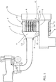
- Figure 1 shows a first embodiment of the invention, a device suitable for being attached to a particle filter or a catalytic converter.
- the particle filter or catalytic converter is not shown to make space for the device according to this embodiment, nevertheless, the longitudinal direction X-X' defined by the particle filter or catalytic converter is indicated.
- the particle filter or catalytic converter has an outlet with a large diameter which is covered by a first baffle (1) having coupling means (16) configured for surrounding the outlet of the particle filter or catalytic converter covering it.
- These coupling means (16) allow attaching the device according to the invention with the particle filter or catalytic converter.
- the first baffle (1) is obtained by means of a stamped aluminum sheet with the edges on its perimeter bent. Following the orientation shown in Figure 1 , a second baffle (2) spaced from the first baffle (1) is shown to the left of the first baffle (1). In this example, the first baffle (1) and the second baffle (2) are arranged parallel to one another.
- a first perimetral casing (7) extends between the first baffle (1) and the second baffle (2) defining a first chamber (3) intended for housing a coolant fluid, preferably a liquid.
- this first casing (7) has been configured according to a tubular body with dual stepping, a first stepping housing the first baffle (1) and a second stepping giving rise, by way of the extension of the tubular body, to the coupling means (16) suitable for surrounding the particulate filter or the catalytic converter.
- first baffle (1) would be shown in symmetrical arrangement with respect to the second baffle (2); i.e., the perimetral bending would be oriented in opposition to the orientation shown by the perimetral bending of the second baffle (2), both being fitted in the first casing (7).
- the coupling means (16) would be an independent part welded to the body formed by the first baffle (1) and the first casing (7).
- This alternative option allows configuring the part forming the coupling means (16) with an angle which in turn results in a seat that is oblique with respect to the longitudinal direction defined by the particulate filter or the catalytic converter on which it is attached.
- the first baffle (1) and the coupling means (16) collect all the gases exiting the particulate filter or catalytic converter surrounded by the coupling means (16). Therefore, the gases exiting the particulate filter or the catalytic converter can only circulate through the pipes which are attached to the first baffle (1).
- the second baffle (2) has also been configured by means of a stamped layer with bent edges on its perimeter except in this case it has been coupled to the tubular body formed by the first casing (7) externally surrounding it at the end shown to the left.
- Both the first baffle (1) and the second baffle (2) have perforations housing the ends of a plurality of cooling pipes (4).
- Each of these cooling pipes (4) puts the gas outlet of the particulate filter or of the catalytic converter in fluid communication; i.e., the space located to the right of the first baffle (1) with the space located to the left of the second baffle (2).
- the cooling pipes (4) are corrugated tubes for increasing the heat exchange between the gas circulating through the inside of the cooling pipe (4) and the coolant fluid covering it externally in an operating mode.
- the first chamber (3) has an inlet and an outlet (11, 12) not shown in this Figure 1 but shown in Figure 2 .
- the sectioning of each of the drawings may or may not show a partial intersection with the inlet or outlet (11, 12) depending on if the section plane coincides with said inlet or outlet (11, 12).
- the second baffle (2) is in turn covered by a second casing (5) surrounding the edges of the second baffle (2) on the perimeter.
- This second casing (5) forms a second chamber (8) and collects the gases exiting the cooling pipes (4) after having been cooled by transferring heat from the gas to the coolant liquid.
- the cooled gases can exit through an outlet (13) which, for example, can reach an EGR valve that is shown in the preceding figure to the left for being introduced in the engine intake again.
- the plurality of cooling pipes (4) is grouped in the upper area such that in the first baffle (1) there is an area with ends of cooling pipes (4) and another area, in the lower part, free of cooling pipes (4).
- This second area is occupied by a segment of exhaust pipe (9) allowing the exit of the exhaust gases without them having to pass through the EGR heat exchanger made up, among others, of the cooling pipes (4).
- the segment of exhaust pipe (9) is in turn housed in a pipe with greater dimensions (14) giving rise to a separation chamber separating the segment of exhaust pipe (9) and the first chamber (3).
- the exhaust pipe (9) in this embodiment extends at least from the first baffle (2) to the second baffle passing through the inside of the first chamber (3) a compact configuration is achieved given that the perimeter limits of the particle filter or catalytic converter are not exceeded in projection according to the longitudinal direction X-X' due to the existence of an additional pipe.
- At least the segment of exhaust pipe (9) passing through the inside of the first chamber (3) has been thermally insulated, heat transfer from the exhaust gases which are not necessarily cooled gases to the coolant liquid where this heat must in turn be discharged by the engine radiator, is prevented.
- the use of two coaxial pipes, the pipe with greater dimensions (14) and the exhaust pipe (9), provides a simple construction for obtaining this thermally insulated segment.
- the second casing (5) covers the perimeter of the second baffle (2) which coincides in projection according to the longitudinal direction X-X' with the first baffle (1) such that the segment of exhaust pipe (9) traverses the second chamber (8) for being prolong in the exhaust line.
- the segment of exhaust pipe (9) located inside the second chamber (8) comprises a portion configured in the form of a bellows (15) for absorbing expansion stresses.
- This segment of pipe traversing the second chamber (8) is subjected to two different temperatures, the temperature of the cooled gas and the temperature of the non-cooled gas. When the device is not operating all the parts are cold and are therefore at the same temperature, nevertheless, in an operating mode the temperatures are different so this temperature difference causes stresses due to differentiated expansions as well.
- this solution allows maintaining the degree of integration even though the pipe passes through the second chamber.
- both the cooling pipes (4) and the exhaust pipe (9) are arranged essentially parallel to one another and to the longitudinal direction X-X'. This orientation favors using the diameter of the particle filter or catalytic converter.
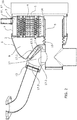
- Figure 2 shows a second embodiment comprising the same elements as the first example shown in the already described Figure 1 , and additionally comprises a bypass valve (17).
- the exhaust pipe (9), prolonged outside the second casing (5), has an opening.
- the second casing (5) has been modified such that the cooled gas outlet (13) has an oblique exit direction directed towards the exhaust pipe (9), particularly close to the position of the opening of the exhaust pipe (9).
- the bypass valve (17) has a first inlet (17.1) in connection with the cooled gas outlet (13) of the second chamber (8), a second inlet (17.2) in connection with the opening of the prolongation of the segment of exhaust pipe (9); and an outlet (17.3) which is in fluid communication with the intake, for example, through an EGR valve.
- the bypass valve (17) allows at least two end positions:
- bypass valve (17) has been configured by means of a flap (17.5) pivoting about a shaft (17.4) where the shaft (17.4) has two planar plates, one suitable for acting as a seat in the first inlet (17.1) of the bypass valve (17) and the other for acting as a seat in the second inlet (17.2) of the bypass valve (17).
- the first end position of the flap (17.5) establishes fluid communication between the second chamber (8) and the pipe exiting towards the engine intake and keeps the communication with the segment of exhaust pipe (9) closed.
- the device operates like in the first embodiment.
- Part of the exhaust gases exiting the particulate filter or the catalytic converter circulate through the heat exchanger made up of the cooling pipes (4) and reach the EGR valve (not shown in this figure) for being reintroduced in the engine intake.
- the other part of the exhaust gases exit directly through the segment of exhaust pipe (9) continuing through the exhaust line.
- This second end position of the flap (17.5) allows introducing hot exhaust gases in the EGR valve to prevent the occurrence of condensates when the engine is still cold after start up.
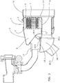
- Figure 3 shows a third embodiment comprising at least the elements described in the first embodiment as well as a heat recovery valve (18).
- the heat recovery valve (18) is a flap valve (18.5) with a rotating shaft (18.4) and two plates acting as a seat in a first inlet (18.1) or in a second inlet (18.2).
- the first inlet (18.1) of the heat recovery valve (18) is in communication with the second cooled gas chamber (8) by means of a small segment of pipe which is shown to be oblique in Figure 3 .
- the cooled gas outlet (13) starts from this small segment so the cooled gas outlet for the exit of cooled gas towards the engine intake cannot be directly closed by the heat recovery valve (18).
- the small oblique segment exits perpendicularly from a surface of the second casing (5) which is also obliquely arranged so that the small oblique segment is oriented towards the valve.
- the second inlet (18.2) of the heat recovery valve (18) is directly fed by the outlet of the segment of exhaust (9), i.e., the entire flow circulating through the segment of exhaust pipe (9) feeds this second inlet (18.2).
- the heat recovery valve (18) allows at least two end positions:
- the operating mode is similar to that of the first embodiment.
- the cooled gas is directed entirely to the engine intake and the gas exiting through the segment of exhaust pipe (9) is directed entirely to the exhaust line.
- the proportion of gas passing through the heat exchanger or through the segment of exhaust pipe (9) will depend on the degree of opening of the EGR valve.
- the exit through the segment of exhaust pipe (9) is blocked so all the gas exiting the particulate filter or the catalytic converter is forced to pass through the heat exchanger.
- the transfer of heat to the coolant fluid is greater, successfully transferring most of the heat which would otherwise be emitted to the atmosphere to the coolant liquid circuit, for example, to reach the nominal temperature of the engine sooner when starting up.
- the shaft (18.4) is located in the convergence of the oblique surface of the second casing (5) and the segment of exhaust pipe (9) emerging perpendicular to the first baffle (1) and second baffle (2).
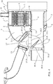
- Figure 4 shows a fourth embodiment comprising at least the elements described in the first embodiment as well as a bypass valve (17) and a heat recovery valve (18).
- the bypass valve (17) is located in a location similar to that of the second embodiment and the heat recovery valve (19) is located in a location which has been described in the third embodiment.
- the device according to this embodiment comprises:
- the connection is made through the first outlet (19.1) of the second heat recovery valve (19).
- the passage between the inner chamber of one valve (17) and the other valve (19) is closed when any of the valves closes the passage, for example, if the bypass valve (17) closes the second inlet (17.2) or if the second heat recovery valve (19) closes the first outlet (19.1).
- the position of the valves (17, 19) corresponding to the bypass valve (17) closing the second inlet (17.2) and the second heat recovery valve (19) closing the first outlet (19.1) shows a configuration operating in the same manner as the first embodiment.
- Figure 4 shows, below the seat of the second outlet (19.2), a passage (19.6) maintaining permanent communication between both sides even though the second heat recovery valve (19) is in the end position closing the second outlet (19.2).
- This passage (19.6) allows the engine to keep on running even though the second heat recovery valve (19) is completely closing the second outlet (19.2) and therefore closing the exhaust.
- the presence of this passage (19.6) is optional since the possibility of stopping the engine by completely closing the exhaust, for example in an emergency situation, may be desirable.
- the position of the valves (17, 19) corresponding to the bypass valve (17) closing the second inlet (17.2) and the second heat recovery valve (19) closing the second outlet (19.2) shows a configuration operating in a manner similar to that performed by the third embodiment for heat recovery since almost the entire gas flow exiting the particulate filter or the catalytic converter is forced to pass through the heat exchanger.
- the difference thereof with respect to the third embodiment is that the existence of the passage (19.6) in the exhaust is that which would allow the exit of the exhaust gases, and these gases would not have passed through the heat exchanger, transferring their heat.
- a non-exclusive alternative to using the passage (19.6) is the use of intermediate positions of the second heat recovery valve (19).
- valves (17, 19) corresponding to the bypass valve (17) closing the first inlet (17.1) and the second heat recovery valve (19) closing the second outlet (19.2) cancels out the heat exchanger forcing all the gas to enter the intake, for example, to prevent condensate formation.
- closing the second outlet (19.2) makes sense if there is a passage (19.6) which assures a minimum outlet flow towards the exhaust, and, alternatively, partial closing of the second outlet (19.2) using intermediate positions of the second heat recovery valve (19) makes sense.
- this particular solution has a regulated exhaust constricting function.
- valves (17, 18) which allow intermediate positions located between the end positions.
- the partial opening of the second heat recovery valve (19) constricts the outlet of the exhaust modifying the pressure and therefore either the amount of hot gas flow reintroduced in the intake or the amount of flow passing either towards the exchanger or towards the exhaust line.
- the position of the shafts (17.4, 19.4) located in an alternate position at both sides of the communication between valves allow keeping the same degree of integration.
- FIG. 5 shows the first embodiment where two hoods (1.1, 2.1) have been added, one in the first baffle (1) and another in the second baffle (2).
- Each hood (1.1, 2.1) covers the inlet or outlet of a set of ends of cooling pipes (4), preferably two thirds. Of these two thirds of the tubes, one third is covered on both sides by both hoods (1.1, 2.1).
- a one third proportion is suitable when the cooling pipes (4) have the same section, being able to be different if the sections of said pipes (4) are not the same.
- This solution can be extrapolated using an odd number of gas passages through the first chamber (3).
- the cooling pipes (4) extend from the first baffle (1) to the second baffle (2) such that they communicate the outlet of the particle filter or catalytic converter with the second chamber (8) for the passage and cooling of the exhaust gases passing therethrough, it must be interpreted that they are communicated with one another either directly or indirectly when multiple passages through the exchanger are used.
- the device can also comprise an emergency filter for filtering solid particles such as ceramic particles.
- filters can be arranged at the inlet of the device, at the outlet of the heat exchanger coinciding with the region where the cooling pipes (4) are located, at the second inlet of the bypass valve (17.2), at the gas outlet for gases intended for reaching the engine intake or in a combination of any of the above.
- This emergency filter is formed by a metal mesh covering the section of passage to be filtered.
- control system for controlling the EGR system is that which determines the position of the valves depending on the parameters determining recirculated gas management.
Landscapes
- Engineering & Computer Science (AREA)
- Mechanical Engineering (AREA)
- General Engineering & Computer Science (AREA)
- Chemical & Material Sciences (AREA)
- Combustion & Propulsion (AREA)
- Physics & Mathematics (AREA)
- Thermal Sciences (AREA)
- Exhaust-Gas Circulating Devices (AREA)
- Exhaust Gas After Treatment (AREA)
- Chemical Kinetics & Catalysis (AREA)
- Health & Medical Sciences (AREA)
- Toxicology (AREA)
Claims (19)
- Integrierte Abgasmanagement-Vorrichtung, dadurch gekennzeichnet, dass sie umfasst:- eine erste Trennwand (1) mit einer Kopplungseinrichtung (16),- eine zweite Trennwand (2), die von der ersten Trennwand (1) beabstandet ist,- ein erstes Außengehäuse (7), das sich so zwischen der ersten Trennwand (1) und der zweiten Trennwand (2) erstreckt, dass es eine erste Kammer (3) bildet, die zum Aufnehmen eines Kühlfluids bestimmt ist,- ein zweites Gehäuse (5), das so angeordnet ist, dass es wenigstens einen Teil der Fläche der zweiten Trennwand (2), die der zu der ersten Kammer (3) hin gerichteten Fläche gegenüberliegt, so abdeckt, dass eine zweite Kammer (8) zum Sammeln gekühlter Abgase gebildet wird,- ein oder mehrere Kühlrohr/e (4), das/die im Inneren der ersten Kammer (3) aufgenommen ist/sind, wobei jedes Rohr (4) so an einem Ende an der ersten Trennwand (1) und an dem zweiten Ende an der zweiten Trennwand (2) angebracht ist, dass es Verbindung des Auslasses des Partikelfilters oder Katalysators mit der zweiten Kammer (8) zum Durchlassen und Kühlen der hindurchtretenden Abgase herstellt,- einen Einlass (11) und einen Auslass (12) der ersten Kammer (3) zum Durchlassen von Kühlfluid durch die erste Kammer (3),- wobei die erste Trennwand (1) einen ersten Bereich, in dem die Kühlrohre (4) verteilt sind, sowie einen zweiten Bereich aufweist, der frei von Kühlrohren (4) ist; und- ein Segment eines Auspuffrohrs (9), das über den von Rohren (4) freien zweiten Bereich in Verbindung mit dem Auslass des Partikelfilters oder des Katalysators zum Austritt von Abgasen an der ersten Trennwand (1) angebracht ist,wobei die zweite Kammer (8) einen Auslass für gekühltes Gas aufweist, der dazu bestimmt ist, bis zu der Einlassöffnung des Motors zu reichen,
dadurch gekennzeichnet, dass die Kopplungseinrichtung (16) so ausgeführt ist, dass sie den Auslass eines Partikelfilters oder eines Katalysators umschließt. - Vorrichtung nach Anspruch 1, dadurch gekennzeichnet, dass sich das Auspuffrohr (9) wenigstens von der ersten Trennwand (1) zu der zweiten Trennwand (2) erstreckt und durch den Innenraum der ersten Kammer (3) hindurch verläuft.
- Vorrichtung nach Anspruch 2, dadurch gekennzeichnet, dass wenigstens die Oberfläche des Segments des Auspuffohrs (9), das durch den Innenraum der ersten Kammer (3) hindurch verläuft, thermisch isoliert ist, um Wärmeübertragung von den Abgasen auf die Kühlflüssigkeit zu verhindern.
- Vorrichtung nach Anspruch 3, dadurch gekennzeichnet, dass die Oberfläche des Segments des Auspuffrohrs (9), das durch den Innenraum der ersten Kammer (3) hindurch verläuft, im Inneren eines Segments eines Rohrs (14) mit größeren Abmessungen aufgenommen ist, so dass eine Trennkammer entsteht, die das Segment des Abgasrohrs (9) und die erste Kammer (3) trennt.
- Vorrichtung nach einem der vorangehenden Ansprüche, dadurch gekennzeichnet, dass das Segment des Auspuffrohrs (9) durch den Innenraum der zweiten Kammer (8) hindurch verläuft.
- Vorrichtung nach dem vorangehenden Anspruch, dadurch gekennzeichnet, dass das Segment des Abgasrohrs (9), das im Inneren der zweiten Kammer (8) aufgenommen ist, einen Abschnitt umfasst, der in Form eines Balgs (15) ausgeführt ist, um Ausdehnungsspannungen zu absorbieren.
- Vorrichtung nach einem der vorangehenden Ansprüche, dadurch gekennzeichnet, dass die Kühlrohre (4) und das Segment des Auspuffrohrs (9) im Wesentlichen parallel zueinander angeordnet sind.
- Vorrichtung nach einem der vorangehenden Ansprüche, dadurch gekennzeichnet, dass sie ein Umleitventil (17) mit einem ersten Einlass (17.1) in Verbindung mit der zweiten Kammer (8), einem zweiten Einlass (17.2) in Verbindung mit dem Segment des Auspuffrohrs (9) sowie den Auslass umfasst, der mit Zugang zu dem AGR-Ventil in Verbindung mit dem Auslass (13) für gekühltes Gas steht, wobei das Ventil (17) wenigstens zwei Endpositionen ermöglicht:- eine erste Position, in der der erste Einlass (17.1) in Kontakt mit dem Auslass (17.3) ist und der zweite Einlass (17.2) geschlossen gehalten wird; und- eine zweite Position, in der der zweite Einlass (17.2) in Kontakt mit dem Auslass (17.3) ist und der erste Einlass (17.1) geschlossen gehalten wird.
- Vorrichtung nach Anspruch 8, dadurch gekennzeichnet, dass:- das Segment des Auspuffrohrs (9) an der seitlichen Fläche, an der sich der zweite Einlass (17.2) des Umleitventils (17) befindet, sich in einer senkrechten Anordnung, insbesondere über das zweite Gehäuse (5), an die zweite Trennwand (2) anschließt, wenn das Segment des Auspuffrohrs (9) in der zweiten Kammer (3) aufgenommen ist,- die Fläche des zweiten Gehäuses (5), an der sich der erste Einlass (17.1) des Umleitventils (17) befindet, schräg angeordnet und zu dem Segment des Auspuffrohrs (9) hin ausgerichtet ist,wobei das Umleitventil (17) aus einer Klappe (17.5) besteht, die sich um eine Welle (17.4) herum dreht und die entweder den ersten Einlass (17.1) schließt oder den zweiten Einlass (17.2) schließt, und es so eingerichtet ist, dass sich die Welle (17.4) in dem Hohlraum befindet, der sich dort befindet, wo die Fläche des Auspuffrohrs (9) und die schräg angeordnete Fläche des zweiten Gehäuses (5) zusammentreffen.
- Vorrichtung nach einem der Ansprüche 1 bis 7, dadurch gekennzeichnet, dass sie ein Wärmerückgewinnungsventil (18) mit einem ersten Einlass (18.1) in Verbindung mit der zweiten Kammer (8), einem zweiten Einlass (18.2) in Verbindung mit dem Ende des Segments des Auspuffrohrs (9) sowie einem Auslass (18.3) umfasst, der in Verbindung mit dem Abgas steht, wobei das Wärmerückgewinnungsventil (18) wenigstens zwei Endpositionen ermöglicht:- eine erste Position, in der der erste Einlass (18.1) in Kontakt mit dem Auslass (18.3) ist und der zweite Einlass (18.2) geschlossen gehalten wird; und- eine zweite Position, in der der zweite Einlass (18.2) in Kontakt mit dem Auslass (18.3) ist und der erste Einlass (18.1) geschlossen gehalten wird,wobei die zweite Kammer (8) einen Auslass (13) für gekühltes Gas ohne Durchlass durch das Wärmerückgewinnungsventil (18) hält.
- Vorrichtung nach Anspruch 10, dadurch gekennzeichnet, dass:- das Segment des Auspuffrohrs (9), an dessen Ende sich der zweite Einlass (18.2) des Wärmerückgewinnungsventils (18) befindet, sich in einer senkrechten Anordnung, insbesondere über das zweite Gehäuse (5), an die zweite Trennwand (2) anschließt, wenn das Segment des Auspuffrohrs (9) in der zweiten Kammer (3) aufgenommen ist,- die Fläche des zweiten Gehäuses (5), an der sich der erste Einlass (18.1) des Wärmerückgewinnungsventils (18) befindet, schräg angeordnet und zu dem Segment des Auspuffrohrs (9) hin ausgerichtet ist,wobei das Wärmerückgewinnungsventil (18) aus einer Klappe (18.5) besteht, die sich um eine Welle (18.4) herum dreht und die entweder den ersten Einlass (18.1) schließt oder den zweiten Einlass (18.2) schließt, und es so eingerichtet ist, dass sich die Welle (18.4) in dem Hohlraum befindet, der sich dort befindet, wo die Fläche des Auspuffrohrs (9) und die schräg angeordnete Fläche des zweiten Gehäuses (5) zusammentreffen.
- Vorrichtung nach einem der Ansprüche 1 bis 7, dadurch gekennzeichnet, dass sie umfasst:- ein Umleitventil (17) mit einem ersten Einlass (17.1) in Verbindung mit der zweiten Kammer (8), einem zweiten Einlass (17.2) in Verbindung mit dem Segment des Abgasrohrs (9) sowie einem Auslass (17.3), der mit Zugang zu dem AGR-Ventil in Verbindung mit dem Auslass (13) für gekühltes Gas steht, wobei das Umleitventil (17) wenigstens zwei Endpositionen ermöglicht:o eine erste Position, in der der erste Einlass (17.1) in Kontakt mit dem Auslass (17.3) ist und der zweite Einlass (17.2) geschlossen gehalten wird;o eine zweite Position, in der der zweite Einlass (17.2) in Kontakt mit dem Auslass (17.3) ist und der erste Einlass (17.1) geschlossen gehalten wird,- ein zweites Ventil (19) mit einem ersten Auslass (19.1) in Verbindung mit dem zweiten Einlass (17.2) des Umleitventils (17), einem Einlass (19.3) in Verbindung mit dem Ende des Segments des Auspuffrohrs (9) sowie einem zweiten Auslass (19.2), der in Verbindung mit der Abgasleitung steht, wobei das zweite Ventil (19) wenigstens zwei Endpositionen ermöglicht:o eine erste Position, in der der Einlass (19.3) in Kontakt mit dem ersten Auslass (19.1) ist und der zweite Auslass (19.2) geschlossen gehalten wird; undo eine zweite Position, in der der Einlass (19.3) in Kontakt mit dem zweiten Auslass (19.2) ist und der erste Auslass (19.1) geschlossen gehalten wird.
- Vorrichtung nach Anspruch 12, dadurch gekennzeichnet, dass:- das Segment des Auspuffrohrs (9) dort, wo sich die Verbindung des zweiten Einlasses (17.2) des Umleitventils (17) befindet, sich in einer senkrechten Anordnung, insbesondere über das zweite Gehäuse (5), an die zweite Trennwand (2) anschließt, wenn das Segment des Auspuffrohrs (9) in der zweiten Kammer (3) aufgenommen ist,- die Fläche des zweiten Gehäuses (5), an der sich der erste Einlass (17.1) des Umleitventils (17) befindet, schräg angeordnet und zu dem Segment des Auspuffrohrs (9) hin ausgerichtet ist,wobei- das Umleitventil (17) aus einer Klappe (17.5) besteht, die sich um eine Welle (17.4) herum dreht und die entweder den ersten Einlass (17.1) schließt oder den zweiten Einlass (17.2) schließt, und es so eingerichtet ist, dass sich die Welle (17.4) in dem Hohlraum befindet, der sich dort befindet, wo die Fläche des Auspuffrohrs (9) und die schräg angeordnete Fläche des zweiten Gehäuses (5) zusammentreffen; und- das zweite Ventil (19) aus einer Klappe (19.5) besteht, die sich um eine Welle (19.4) herum dreht und die entweder den ersten Auslass (19.1) schließt oder den zweiten Auslass (19.2) schließt, und es so eingerichtet ist, dass seine Welle (19.4) in der Längsrichtung, in der sich das Segment des Auspuffrohrs (9) erstreckt, einer Position der Welle (17.4) des Umleitventils (17) gegenüberliegend angeordnet ist.
- Vorrichtung nach Anspruch 12 oder 13, dadurch gekennzeichnet, dass das zweite Ventil (19) einen Durchlass (19.6) aufweist, der selbst dann Verbindung zwischen beiden Seiten des zweiten Auslasses (19.2) herstellt, wenn die Klappe (19.5) des zweiten Ventils (19) den zweiten Auslass (19.2) schließt.
- Vorrichtung nach einem der Ansprüche 8 bis 14, wobei ein oder mehr Ventil/e Zwischenpositionen zwischen den zwei Endpositionen ermöglicht/ermöglichen.
- Vorrichtung nach einem der vorangehenden Ansprüche, dadurch gekennzeichnet, dass das AGR-Ventil an ihrem Auslass angeordnet ist, der dazu bestimmt ist, bis zu der Einlassöffnung des Motors zu reichen.
- Vorrichtung nach Anspruch 16, dadurch gekennzeichnet, dass, wenn die Vorrichtung ein Umleitventil (17) aufweist, das AGR-Ventil in den Auslass (17.3) des Umleitventils integriert ist.
- Vorrichtung nach einem der vorangehenden Ansprüche, dadurch gekennzeichnet, dass sie wenigstens eine erste Haube (1.1) an der Öffnung eines Teils der Kühlrohre (4) der ersten Trennwand (1) sowie eine zweite Haube (2.1) an der Öffnung eines Teils der Kühlrohre (4) an der zweiten Trennwand (2) umfasst, die sich dazu eignen, eine ungerade Zahl an Strömungsdurchlassen durch die Kühlrohre (4) hindurch herzustellen.
- AGR-System, das eine Vorrichtung nach einem der vorangehenden Ansprüche sowie ein Steuerungssystem zum Steuern der Position der Ventile der Vorrichtung umfasst.
Priority Applications (1)
| Application Number | Priority Date | Filing Date | Title |
|---|---|---|---|
| EP13802634.9A EP2932080B1 (de) | 2012-12-11 | 2013-12-10 | Integrierte abgasmanagementvorrichtung |
Applications Claiming Priority (3)
| Application Number | Priority Date | Filing Date | Title |
|---|---|---|---|
| EP12382491.4A EP2743488A1 (de) | 2012-12-11 | 2012-12-11 | Eingebaute Abgasverwaltungsvorrichtung |
| PCT/EP2013/076063 WO2014090792A1 (en) | 2012-12-11 | 2013-12-10 | Built-in exhaust gas management device |
| EP13802634.9A EP2932080B1 (de) | 2012-12-11 | 2013-12-10 | Integrierte abgasmanagementvorrichtung |
Publications (2)
| Publication Number | Publication Date |
|---|---|
| EP2932080A1 EP2932080A1 (de) | 2015-10-21 |
| EP2932080B1 true EP2932080B1 (de) | 2017-02-22 |
Family
ID=47631239
Family Applications (2)
| Application Number | Title | Priority Date | Filing Date |
|---|---|---|---|
| EP12382491.4A Withdrawn EP2743488A1 (de) | 2012-12-11 | 2012-12-11 | Eingebaute Abgasverwaltungsvorrichtung |
| EP13802634.9A Not-in-force EP2932080B1 (de) | 2012-12-11 | 2013-12-10 | Integrierte abgasmanagementvorrichtung |
Family Applications Before (1)
| Application Number | Title | Priority Date | Filing Date |
|---|---|---|---|
| EP12382491.4A Withdrawn EP2743488A1 (de) | 2012-12-11 | 2012-12-11 | Eingebaute Abgasverwaltungsvorrichtung |
Country Status (5)
| Country | Link |
|---|---|
| US (1) | US20150308388A1 (de) |
| EP (2) | EP2743488A1 (de) |
| KR (1) | KR20150117252A (de) |
| CN (1) | CN104981601A (de) |
| WO (1) | WO2014090792A1 (de) |
Cited By (1)
| Publication number | Priority date | Publication date | Assignee | Title |
|---|---|---|---|---|
| KR20220095895A (ko) | 2020-12-30 | 2022-07-07 | 한국기계연구원 | 배출가스 촉매전환효율 향상을 위한 흡기 온도 관리 장치 |
Families Citing this family (15)
| Publication number | Priority date | Publication date | Assignee | Title |
|---|---|---|---|---|
| EP2781730A1 (de) * | 2013-03-19 | 2014-09-24 | Borgwarner Inc. | Kompakte Vorrichtung zur Abgasverwaltung in einem AGR-System |
| DE102013011953A1 (de) * | 2013-07-18 | 2015-01-22 | Brückner Maschinenbau GmbH & Co. KG | Seitenführungsschiene für ein Transportsystem, insbesondere eine Reckanlage |
| EP2955362B1 (de) | 2014-06-10 | 2017-08-30 | Borgwarner Emissions Systems Spain, S.L.U. | Integrierte Abgasmanagementvorrichtung |
| ES2696980T3 (es) | 2015-09-14 | 2019-01-21 | Bosal Emission Control Systems Nv | Componente de recuperación de calor para un sistema de gases de escape de un motor de combustión interna |
| FR3041033B1 (fr) * | 2015-09-15 | 2017-09-15 | Renault Sas | Ligne d'echappement et circuit d'air pour moteur de vehicule automobile permettant une integration optimisee du circuit de recirculation des gaz d'echappement |
| DE102016200284B4 (de) * | 2016-01-13 | 2019-06-13 | Ford Global Technologies, Llc | Abgastemperaturregulation in einem Bypasskanal eines Abgasrückführungssystems |
| WO2017126118A1 (ja) * | 2016-01-22 | 2017-07-27 | フタバ産業株式会社 | 排気熱回収装置 |
| US9874129B2 (en) * | 2016-04-05 | 2018-01-23 | Ford Global Technologies, Llc | SCR device |
| EP3339618A1 (de) * | 2016-12-20 | 2018-06-27 | Borgwarner Emissions Systems Spain, S.L.U. | Ventil zur konstruktion einer kompakten wärmerückgewinnungseinheit |
| FR3062416A1 (fr) * | 2017-01-27 | 2018-08-03 | Faurecia Systemes D'echappement | Dispositif de traitement des gaz d'echappement, ligne d'echappement et procede de fabrication correspondant |
| FR3074523B1 (fr) * | 2017-12-04 | 2021-02-19 | Faurecia Systemes Dechappement | Dispositif compact de purification et de recirculation de gaz d'echappement |
| KR102540546B1 (ko) * | 2018-08-23 | 2023-06-05 | 현대자동차주식회사 | 가솔린 egr 시스템의 밸브개방 제어장치 및 방법 |
| EP3722587A1 (de) * | 2019-04-12 | 2020-10-14 | Borgwarner Emissions Systems Spain, S.L.U. | Abgasmanagementsystem |
| US11486337B2 (en) * | 2019-09-06 | 2022-11-01 | Deere & Company | Integrated exhaust system apparatus |
| CN113787076A (zh) * | 2021-09-06 | 2021-12-14 | 哈尔滨盛迪电力设备有限公司 | 带有紧急排风门的折叠式自动排风装置 |
Family Cites Families (37)
| Publication number | Priority date | Publication date | Assignee | Title |
|---|---|---|---|---|
| US1745492A (en) * | 1925-12-31 | 1930-02-04 | Kelch Ventilating Heater Compa | Combined heater and muffler for automobiles |
| US4930571A (en) * | 1985-05-08 | 1990-06-05 | Industrial Energy Corporation | Heat recovery apparatus |
| US5329765A (en) * | 1993-01-22 | 1994-07-19 | Sung-Chuan Mai Et Al. | Exhaust pipe assembly for treating the exhaust of an internal combustion engine |
| US6684938B2 (en) * | 1999-01-20 | 2004-02-03 | Hino Motors, Ltd. | EGR cooler |
| US6347511B1 (en) * | 1999-12-21 | 2002-02-19 | Ford Global Technologies, Inc. | Exhaust gas purification system for lean burn engine |
| EP1343963B1 (de) * | 2000-12-19 | 2008-04-09 | Valeo Termico S.A. | Wärmetauschermodul, das insbesondere für ein abgasrückführsystem ausgelegt ist |
| ES2174739B1 (es) * | 2000-12-19 | 2003-11-01 | Valeo Termico Sa | Modulo intercambiador de calor para un sistema de recirculacion de gases de escape. |
| DE10203003B4 (de) * | 2002-01-26 | 2007-03-15 | Behr Gmbh & Co. Kg | Abgaswärmeübertrager |
| FR2838776B1 (fr) * | 2002-04-17 | 2005-07-08 | Johnson Contr Automotive Elect | Dispositif de refroidissement a deux voies de circulation pour les gaz d'echappement d'un moteur a combustion interne |
| ES2209618B1 (es) * | 2002-05-28 | 2005-08-16 | Estampaciones Noroeste, S.A. | Intercambiador de calor para un sistema "egr" con un conducto de derivacion integrado. |
| EP1685322A1 (de) * | 2003-10-17 | 2006-08-02 | Honeywell International, Inc. | Interner bypass für abgaskühler |
| DE10355649B4 (de) * | 2003-11-28 | 2008-02-14 | Benteler Automobiltechnik Gmbh | Längsdurchströmter Abgaskühler |
| JP2007255719A (ja) * | 2004-04-30 | 2007-10-04 | T Rad Co Ltd | 熱交換器の連結構造 |
| JP2006070852A (ja) * | 2004-09-03 | 2006-03-16 | Mitsubishi Electric Corp | 排気ガス還流装置 |
| DE102004061809A1 (de) * | 2004-12-22 | 2006-07-06 | Robert Bosch Gmbh | Heiz- und/oder Kühlsystem für ein Kraftfahrzeug |
| JP2007009724A (ja) * | 2005-06-28 | 2007-01-18 | Denso Corp | 排気ガス用熱交換装置 |
| JP2007023911A (ja) * | 2005-07-19 | 2007-02-01 | Denso Corp | 排気ガス再循環装置 |
| DE102005040612A1 (de) * | 2005-08-27 | 2007-03-01 | Behr Gmbh & Co. Kg | Abgaswärmeübertrager |
| JP4931390B2 (ja) * | 2005-09-12 | 2012-05-16 | 臼井国際産業株式会社 | Egrガス冷却装置 |
| ES2322728B1 (es) * | 2005-11-22 | 2010-04-23 | Dayco Ensa, S.L. | Intercambiador de calor de tres pasos para un sistema "egr". |
| WO2007089565A1 (en) * | 2006-01-27 | 2007-08-09 | Borgwarner Inc. | Mixing unit for low pressure-egr condensate into the compressor |
| WO2007104580A2 (de) * | 2006-03-16 | 2007-09-20 | Behr Gmbh & Co. Kg | Wärmetauscher für ein kraftfahrzeug |
| DE102006042936A1 (de) * | 2006-09-13 | 2008-03-27 | Modine Manufacturing Co., Racine | Wärmeaustauscher, insbesondere Abgaswärmeaustauscher |
| JP4281789B2 (ja) * | 2006-12-06 | 2009-06-17 | トヨタ自動車株式会社 | 排気熱回収装置 |
| CN101070767A (zh) * | 2007-03-20 | 2007-11-14 | 张德明 | 机动车尾气再循环旁通冷却装置 |
| DE102007036301A1 (de) * | 2007-07-31 | 2009-02-05 | Behr Gmbh & Co. Kg | Wärmetauschergehäuse, Wärmetauscher oder Baueinheit mit einem oder mehreren Wärmetauschern, Abgasrückführsystem, Ladeluftzuführsystem und Verwendung des Wärmetauschers |
| JP4553023B2 (ja) * | 2008-03-21 | 2010-09-29 | 株式会社デンソー | 排気ガス切替弁 |
| JP4793454B2 (ja) * | 2009-02-06 | 2011-10-12 | 株式会社デンソー | 高圧egr装置 |
| US20100229540A1 (en) * | 2009-03-11 | 2010-09-16 | Indmar Products Company Inc. | Combination Liquid-Cooled Exhaust Manifold Assembly And Catalytic Converter Assembly For A Marine Engine |
| FR2943384B1 (fr) * | 2009-03-23 | 2011-03-04 | Renault Sas | Circuit d'echappement de vehicule automobile |
| DE102009058609A1 (de) * | 2009-12-17 | 2011-06-22 | Volkswagen AG, 38440 | Einrichtung zur Abgasrückführung sowie Verfahren zur Erwärmung eines Kühlmediums einer Brennkraftmaschine und Verwendung der Einrichtung zur Abgasrückführung |
| US8375926B2 (en) * | 2010-02-01 | 2013-02-19 | Deere & Company | Moisture purging in an EGR system |
| DE102010003798A1 (de) * | 2010-04-09 | 2011-10-13 | Ford Global Technologies, Llc | Niederdruck-Abgasrückführsystem mit Wärmerückgewinnung |
| US8769940B2 (en) * | 2010-05-05 | 2014-07-08 | Cummins Power Generation Ip, Inc. | Marine exhaust catalyst |
| US9664087B2 (en) * | 2010-07-22 | 2017-05-30 | Wescast Industries, Inc. | Exhaust heat recovery system with bypass |
| CA2769913C (en) * | 2011-03-03 | 2013-09-24 | Toru Hisanaga | Exhaust heat recovery device |
| US8650864B2 (en) * | 2011-10-19 | 2014-02-18 | Indmar Products Company Inc. | Combination liquid-cooled exhaust manifold assembly and catalytic converter assembly for a marine engine |
-
2012
- 2012-12-11 EP EP12382491.4A patent/EP2743488A1/de not_active Withdrawn
-
2013
- 2013-12-10 WO PCT/EP2013/076063 patent/WO2014090792A1/en not_active Ceased
- 2013-12-10 US US14/651,465 patent/US20150308388A1/en not_active Abandoned
- 2013-12-10 CN CN201380064765.5A patent/CN104981601A/zh active Pending
- 2013-12-10 EP EP13802634.9A patent/EP2932080B1/de not_active Not-in-force
- 2013-12-10 KR KR1020157017392A patent/KR20150117252A/ko not_active Ceased
Non-Patent Citations (1)
| Title |
|---|
| None * |
Cited By (2)
| Publication number | Priority date | Publication date | Assignee | Title |
|---|---|---|---|---|
| KR20220095895A (ko) | 2020-12-30 | 2022-07-07 | 한국기계연구원 | 배출가스 촉매전환효율 향상을 위한 흡기 온도 관리 장치 |
| KR20230098508A (ko) | 2020-12-30 | 2023-07-04 | 한국기계연구원 | 배출가스 촉매전환효율 향상을 위한 흡기 온도 관리 장치 |
Also Published As
| Publication number | Publication date |
|---|---|
| KR20150117252A (ko) | 2015-10-19 |
| CN104981601A (zh) | 2015-10-14 |
| WO2014090792A1 (en) | 2014-06-19 |
| US20150308388A1 (en) | 2015-10-29 |
| EP2743488A1 (de) | 2014-06-18 |
| EP2932080A1 (de) | 2015-10-21 |
Similar Documents
| Publication | Publication Date | Title |
|---|---|---|
| EP2743488A1 (de) | Eingebaute Abgasverwaltungsvorrichtung | |
| CA2801607C (en) | Annular heat exchanger | |
| US7210469B1 (en) | Oxidation catalyst coating in a heat exchanger | |
| US9121316B2 (en) | Exhaust gas heat recovery device | |
| JP6186276B2 (ja) | バイパスを備える排熱回収装置 | |
| US7931013B2 (en) | Three-pass heat exchanger for an EGR system | |
| US8261542B2 (en) | System, method, and device for locomotive exhaust gas recirculation cooling and catalyst heating | |
| EP1548267B1 (de) | Agr-kühler | |
| US20090260605A1 (en) | Staged arrangement of egr coolers to optimize performance | |
| US20070089716A1 (en) | Heat exchanger method and apparatus | |
| US7841323B2 (en) | Internal-combustion engine having a cooled exhaust gas recirculation system as well as an exhaust gas manifold | |
| US20110108254A1 (en) | Heat exchanger | |
| CN100573017C (zh) | 气冷式废气热交换器、特别是汽车废气冷却器 | |
| US20150167519A1 (en) | Heat recovery device with standoff heat exchanger mount | |
| JP4099274B2 (ja) | 内燃機関の排気システム | |
| WO2014017014A1 (ja) | Egrシステムおよび排気熱交換システム | |
| JP2019065859A (ja) | 熱回収システム | |
| EP2955362B1 (de) | Integrierte Abgasmanagementvorrichtung | |
| CN113167165A (zh) | 排气热量回收系统 | |
| JP2007046599A (ja) | 内燃機関の排気マニフォールド組立体、同組立体を備えた内燃機関の排出ガス制御装置及び同制御方法 | |
| JP2007239595A (ja) | 排気系熱交換器の配置構造 | |
| EP3517769A1 (de) | Motoreinlass- und -auslasssystem, verbrennungsmotor und verfahren zur bereitstellung eines motoreinlass- und -auslasssystems | |
| JP2006132440A (ja) | Egr装置 | |
| CN113167166B (zh) | 排气热量回收系统 | |
| IT202300008310A1 (it) | Motore a combustione interna con gruppo di refrigerazione per una portata di gas di scarico ricircolati a bassa pressione |
Legal Events
| Date | Code | Title | Description |
|---|---|---|---|
| PUAI | Public reference made under article 153(3) epc to a published international application that has entered the european phase |
Free format text: ORIGINAL CODE: 0009012 |
|
| 17P | Request for examination filed |
Effective date: 20150701 |
|
| AK | Designated contracting states |
Kind code of ref document: A1 Designated state(s): AL AT BE BG CH CY CZ DE DK EE ES FI FR GB GR HR HU IE IS IT LI LT LU LV MC MK MT NL NO PL PT RO RS SE SI SK SM TR |
|
| AX | Request for extension of the european patent |
Extension state: BA ME |
|
| DAX | Request for extension of the european patent (deleted) | ||
| REG | Reference to a national code |
Ref country code: DE Ref legal event code: R079 Ref document number: 602013017748 Country of ref document: DE Free format text: PREVIOUS MAIN CLASS: F02M0025070000 Ipc: F02M0026000000 |
|
| RIC1 | Information provided on ipc code assigned before grant |
Ipc: F02M 26/00 20160101AFI20160406BHEP |
|
| GRAP | Despatch of communication of intention to grant a patent |
Free format text: ORIGINAL CODE: EPIDOSNIGR1 |
|
| INTG | Intention to grant announced |
Effective date: 20160603 |
|
| GRAJ | Information related to disapproval of communication of intention to grant by the applicant or resumption of examination proceedings by the epo deleted |
Free format text: ORIGINAL CODE: EPIDOSDIGR1 |
|
| INTC | Intention to grant announced (deleted) | ||
| GRAS | Grant fee paid |
Free format text: ORIGINAL CODE: EPIDOSNIGR3 |
|
| GRAP | Despatch of communication of intention to grant a patent |
Free format text: ORIGINAL CODE: EPIDOSNIGR1 |
|
| INTG | Intention to grant announced |
Effective date: 20161220 |
|
| GRAA | (expected) grant |
Free format text: ORIGINAL CODE: 0009210 |
|
| AK | Designated contracting states |
Kind code of ref document: B1 Designated state(s): AL AT BE BG CH CY CZ DE DK EE ES FI FR GB GR HR HU IE IS IT LI LT LU LV MC MK MT NL NO PL PT RO RS SE SI SK SM TR |
|
| REG | Reference to a national code |
Ref country code: GB Ref legal event code: FG4D |
|
| REG | Reference to a national code |
Ref country code: CH Ref legal event code: EP |
|
| REG | Reference to a national code |
Ref country code: AT Ref legal event code: REF Ref document number: 869476 Country of ref document: AT Kind code of ref document: T Effective date: 20170315 |
|
| REG | Reference to a national code |
Ref country code: IE Ref legal event code: FG4D |
|
| REG | Reference to a national code |
Ref country code: DE Ref legal event code: R096 Ref document number: 602013017748 Country of ref document: DE |
|
| REG | Reference to a national code |
Ref country code: LT Ref legal event code: MG4D |
|
| REG | Reference to a national code |
Ref country code: NL Ref legal event code: MP Effective date: 20170222 |
|
| REG | Reference to a national code |
Ref country code: AT Ref legal event code: MK05 Ref document number: 869476 Country of ref document: AT Kind code of ref document: T Effective date: 20170222 |
|
| PG25 | Lapsed in a contracting state [announced via postgrant information from national office to epo] |
Ref country code: FI Free format text: LAPSE BECAUSE OF FAILURE TO SUBMIT A TRANSLATION OF THE DESCRIPTION OR TO PAY THE FEE WITHIN THE PRESCRIBED TIME-LIMIT Effective date: 20170222 Ref country code: LT Free format text: LAPSE BECAUSE OF FAILURE TO SUBMIT A TRANSLATION OF THE DESCRIPTION OR TO PAY THE FEE WITHIN THE PRESCRIBED TIME-LIMIT Effective date: 20170222 Ref country code: NO Free format text: LAPSE BECAUSE OF FAILURE TO SUBMIT A TRANSLATION OF THE DESCRIPTION OR TO PAY THE FEE WITHIN THE PRESCRIBED TIME-LIMIT Effective date: 20170522 Ref country code: GR Free format text: LAPSE BECAUSE OF FAILURE TO SUBMIT A TRANSLATION OF THE DESCRIPTION OR TO PAY THE FEE WITHIN THE PRESCRIBED TIME-LIMIT Effective date: 20170523 Ref country code: HR Free format text: LAPSE BECAUSE OF FAILURE TO SUBMIT A TRANSLATION OF THE DESCRIPTION OR TO PAY THE FEE WITHIN THE PRESCRIBED TIME-LIMIT Effective date: 20170222 |
|
| PG25 | Lapsed in a contracting state [announced via postgrant information from national office to epo] |
Ref country code: SE Free format text: LAPSE BECAUSE OF FAILURE TO SUBMIT A TRANSLATION OF THE DESCRIPTION OR TO PAY THE FEE WITHIN THE PRESCRIBED TIME-LIMIT Effective date: 20170222 Ref country code: PT Free format text: LAPSE BECAUSE OF FAILURE TO SUBMIT A TRANSLATION OF THE DESCRIPTION OR TO PAY THE FEE WITHIN THE PRESCRIBED TIME-LIMIT Effective date: 20170622 Ref country code: RS Free format text: LAPSE BECAUSE OF FAILURE TO SUBMIT A TRANSLATION OF THE DESCRIPTION OR TO PAY THE FEE WITHIN THE PRESCRIBED TIME-LIMIT Effective date: 20170222 Ref country code: NL Free format text: LAPSE BECAUSE OF NON-PAYMENT OF DUE FEES Effective date: 20170222 Ref country code: LV Free format text: LAPSE BECAUSE OF FAILURE TO SUBMIT A TRANSLATION OF THE DESCRIPTION OR TO PAY THE FEE WITHIN THE PRESCRIBED TIME-LIMIT Effective date: 20170222 Ref country code: ES Free format text: LAPSE BECAUSE OF FAILURE TO SUBMIT A TRANSLATION OF THE DESCRIPTION OR TO PAY THE FEE WITHIN THE PRESCRIBED TIME-LIMIT Effective date: 20170222 Ref country code: AT Free format text: LAPSE BECAUSE OF FAILURE TO SUBMIT A TRANSLATION OF THE DESCRIPTION OR TO PAY THE FEE WITHIN THE PRESCRIBED TIME-LIMIT Effective date: 20170222 Ref country code: BG Free format text: LAPSE BECAUSE OF FAILURE TO SUBMIT A TRANSLATION OF THE DESCRIPTION OR TO PAY THE FEE WITHIN THE PRESCRIBED TIME-LIMIT Effective date: 20170522 |
|
| PG25 | Lapsed in a contracting state [announced via postgrant information from national office to epo] |
Ref country code: EE Free format text: LAPSE BECAUSE OF FAILURE TO SUBMIT A TRANSLATION OF THE DESCRIPTION OR TO PAY THE FEE WITHIN THE PRESCRIBED TIME-LIMIT Effective date: 20170222 Ref country code: SK Free format text: LAPSE BECAUSE OF FAILURE TO SUBMIT A TRANSLATION OF THE DESCRIPTION OR TO PAY THE FEE WITHIN THE PRESCRIBED TIME-LIMIT Effective date: 20170222 Ref country code: IT Free format text: LAPSE BECAUSE OF FAILURE TO SUBMIT A TRANSLATION OF THE DESCRIPTION OR TO PAY THE FEE WITHIN THE PRESCRIBED TIME-LIMIT Effective date: 20170222 Ref country code: CZ Free format text: LAPSE BECAUSE OF FAILURE TO SUBMIT A TRANSLATION OF THE DESCRIPTION OR TO PAY THE FEE WITHIN THE PRESCRIBED TIME-LIMIT Effective date: 20170222 Ref country code: RO Free format text: LAPSE BECAUSE OF FAILURE TO SUBMIT A TRANSLATION OF THE DESCRIPTION OR TO PAY THE FEE WITHIN THE PRESCRIBED TIME-LIMIT Effective date: 20170222 |
|
| REG | Reference to a national code |
Ref country code: DE Ref legal event code: R097 Ref document number: 602013017748 Country of ref document: DE |
|
| PG25 | Lapsed in a contracting state [announced via postgrant information from national office to epo] |
Ref country code: DK Free format text: LAPSE BECAUSE OF FAILURE TO SUBMIT A TRANSLATION OF THE DESCRIPTION OR TO PAY THE FEE WITHIN THE PRESCRIBED TIME-LIMIT Effective date: 20170222 Ref country code: PL Free format text: LAPSE BECAUSE OF FAILURE TO SUBMIT A TRANSLATION OF THE DESCRIPTION OR TO PAY THE FEE WITHIN THE PRESCRIBED TIME-LIMIT Effective date: 20170222 Ref country code: SM Free format text: LAPSE BECAUSE OF FAILURE TO SUBMIT A TRANSLATION OF THE DESCRIPTION OR TO PAY THE FEE WITHIN THE PRESCRIBED TIME-LIMIT Effective date: 20170222 |
|
| PLBE | No opposition filed within time limit |
Free format text: ORIGINAL CODE: 0009261 |
|
| STAA | Information on the status of an ep patent application or granted ep patent |
Free format text: STATUS: NO OPPOSITION FILED WITHIN TIME LIMIT |
|
| 26N | No opposition filed |
Effective date: 20171123 |
|
| PG25 | Lapsed in a contracting state [announced via postgrant information from national office to epo] |
Ref country code: SI Free format text: LAPSE BECAUSE OF FAILURE TO SUBMIT A TRANSLATION OF THE DESCRIPTION OR TO PAY THE FEE WITHIN THE PRESCRIBED TIME-LIMIT Effective date: 20170222 |
|
| REG | Reference to a national code |
Ref country code: CH Ref legal event code: PL |
|
| GBPC | Gb: european patent ceased through non-payment of renewal fee |
Effective date: 20171210 |
|
| REG | Reference to a national code |
Ref country code: IE Ref legal event code: MM4A |
|
| PG25 | Lapsed in a contracting state [announced via postgrant information from national office to epo] |
Ref country code: LU Free format text: LAPSE BECAUSE OF NON-PAYMENT OF DUE FEES Effective date: 20171210 Ref country code: MT Free format text: LAPSE BECAUSE OF NON-PAYMENT OF DUE FEES Effective date: 20171210 |
|
| REG | Reference to a national code |
Ref country code: FR Ref legal event code: ST Effective date: 20180831 |
|
| REG | Reference to a national code |
Ref country code: BE Ref legal event code: MM Effective date: 20171231 |
|
| PG25 | Lapsed in a contracting state [announced via postgrant information from national office to epo] |
Ref country code: IE Free format text: LAPSE BECAUSE OF NON-PAYMENT OF DUE FEES Effective date: 20171210 Ref country code: FR Free format text: LAPSE BECAUSE OF NON-PAYMENT OF DUE FEES Effective date: 20180102 |
|
| PG25 | Lapsed in a contracting state [announced via postgrant information from national office to epo] |
Ref country code: CH Free format text: LAPSE BECAUSE OF NON-PAYMENT OF DUE FEES Effective date: 20171231 Ref country code: LI Free format text: LAPSE BECAUSE OF NON-PAYMENT OF DUE FEES Effective date: 20171231 Ref country code: BE Free format text: LAPSE BECAUSE OF NON-PAYMENT OF DUE FEES Effective date: 20171231 Ref country code: GB Free format text: LAPSE BECAUSE OF NON-PAYMENT OF DUE FEES Effective date: 20171210 |
|
| PG25 | Lapsed in a contracting state [announced via postgrant information from national office to epo] |
Ref country code: HU Free format text: LAPSE BECAUSE OF FAILURE TO SUBMIT A TRANSLATION OF THE DESCRIPTION OR TO PAY THE FEE WITHIN THE PRESCRIBED TIME-LIMIT; INVALID AB INITIO Effective date: 20131210 Ref country code: MC Free format text: LAPSE BECAUSE OF FAILURE TO SUBMIT A TRANSLATION OF THE DESCRIPTION OR TO PAY THE FEE WITHIN THE PRESCRIBED TIME-LIMIT Effective date: 20170222 |
|
| PG25 | Lapsed in a contracting state [announced via postgrant information from national office to epo] |
Ref country code: CY Free format text: LAPSE BECAUSE OF FAILURE TO SUBMIT A TRANSLATION OF THE DESCRIPTION OR TO PAY THE FEE WITHIN THE PRESCRIBED TIME-LIMIT Effective date: 20170222 |
|
| PG25 | Lapsed in a contracting state [announced via postgrant information from national office to epo] |
Ref country code: MK Free format text: LAPSE BECAUSE OF FAILURE TO SUBMIT A TRANSLATION OF THE DESCRIPTION OR TO PAY THE FEE WITHIN THE PRESCRIBED TIME-LIMIT Effective date: 20170222 |
|
| PG25 | Lapsed in a contracting state [announced via postgrant information from national office to epo] |
Ref country code: TR Free format text: LAPSE BECAUSE OF FAILURE TO SUBMIT A TRANSLATION OF THE DESCRIPTION OR TO PAY THE FEE WITHIN THE PRESCRIBED TIME-LIMIT Effective date: 20170222 |
|
| PG25 | Lapsed in a contracting state [announced via postgrant information from national office to epo] |
Ref country code: AL Free format text: LAPSE BECAUSE OF FAILURE TO SUBMIT A TRANSLATION OF THE DESCRIPTION OR TO PAY THE FEE WITHIN THE PRESCRIBED TIME-LIMIT Effective date: 20170222 Ref country code: IS Free format text: LAPSE BECAUSE OF FAILURE TO SUBMIT A TRANSLATION OF THE DESCRIPTION OR TO PAY THE FEE WITHIN THE PRESCRIBED TIME-LIMIT Effective date: 20170622 |
|
| P01 | Opt-out of the competence of the unified patent court (upc) registered |
Effective date: 20230327 |
|
| PGFP | Annual fee paid to national office [announced via postgrant information from national office to epo] |
Ref country code: DE Payment date: 20231108 Year of fee payment: 11 |
|
| REG | Reference to a national code |
Ref country code: DE Ref legal event code: R119 Ref document number: 602013017748 Country of ref document: DE |
|
| PG25 | Lapsed in a contracting state [announced via postgrant information from national office to epo] |
Ref country code: DE Free format text: LAPSE BECAUSE OF NON-PAYMENT OF DUE FEES Effective date: 20250701 |