EP2932142B1 - Vanne mélangeuse multivoie et procédé de commande temporelle d'une vanne mélangeuse multivoie - Google Patents
Vanne mélangeuse multivoie et procédé de commande temporelle d'une vanne mélangeuse multivoie Download PDFInfo
- Publication number
- EP2932142B1 EP2932142B1 EP13815380.4A EP13815380A EP2932142B1 EP 2932142 B1 EP2932142 B1 EP 2932142B1 EP 13815380 A EP13815380 A EP 13815380A EP 2932142 B1 EP2932142 B1 EP 2932142B1
- Authority
- EP
- European Patent Office
- Prior art keywords
- connections
- switching element
- mixing valve
- connection
- switching
- Prior art date
- Legal status (The legal status is an assumption and is not a legal conclusion. Google has not performed a legal analysis and makes no representation as to the accuracy of the status listed.)
- Active
Links
Images


Classifications
-
- F—MECHANICAL ENGINEERING; LIGHTING; HEATING; WEAPONS; BLASTING
- F16—ENGINEERING ELEMENTS AND UNITS; GENERAL MEASURES FOR PRODUCING AND MAINTAINING EFFECTIVE FUNCTIONING OF MACHINES OR INSTALLATIONS; THERMAL INSULATION IN GENERAL
- F16K—VALVES; TAPS; COCKS; ACTUATING-FLOATS; DEVICES FOR VENTING OR AERATING
- F16K11/00—Multiple-way valves, e.g. mixing valves; Pipe fittings incorporating such valves
- F16K11/02—Multiple-way valves, e.g. mixing valves; Pipe fittings incorporating such valves with all movable sealing faces moving as one unit
- F16K11/06—Multiple-way valves, e.g. mixing valves; Pipe fittings incorporating such valves with all movable sealing faces moving as one unit comprising only sliding valves, i.e. sliding closure elements
- F16K11/072—Multiple-way valves, e.g. mixing valves; Pipe fittings incorporating such valves with all movable sealing faces moving as one unit comprising only sliding valves, i.e. sliding closure elements with pivoted closure members
- F16K11/076—Multiple-way valves, e.g. mixing valves; Pipe fittings incorporating such valves with all movable sealing faces moving as one unit comprising only sliding valves, i.e. sliding closure elements with pivoted closure members with sealing faces shaped as surfaces of solids of revolution
-
- F—MECHANICAL ENGINEERING; LIGHTING; HEATING; WEAPONS; BLASTING
- F16—ENGINEERING ELEMENTS AND UNITS; GENERAL MEASURES FOR PRODUCING AND MAINTAINING EFFECTIVE FUNCTIONING OF MACHINES OR INSTALLATIONS; THERMAL INSULATION IN GENERAL
- F16K—VALVES; TAPS; COCKS; ACTUATING-FLOATS; DEVICES FOR VENTING OR AERATING
- F16K11/00—Multiple-way valves, e.g. mixing valves; Pipe fittings incorporating such valves
- F16K11/02—Multiple-way valves, e.g. mixing valves; Pipe fittings incorporating such valves with all movable sealing faces moving as one unit
- F16K11/08—Multiple-way valves, e.g. mixing valves; Pipe fittings incorporating such valves with all movable sealing faces moving as one unit comprising only taps or cocks
- F16K11/085—Multiple-way valves, e.g. mixing valves; Pipe fittings incorporating such valves with all movable sealing faces moving as one unit comprising only taps or cocks with cylindrical plug
- F16K11/0856—Multiple-way valves, e.g. mixing valves; Pipe fittings incorporating such valves with all movable sealing faces moving as one unit comprising only taps or cocks with cylindrical plug having all the connecting conduits situated in more than one plane perpendicular to the axis of the plug
-
- F—MECHANICAL ENGINEERING; LIGHTING; HEATING; WEAPONS; BLASTING
- F24—HEATING; RANGES; VENTILATING
- F24D—DOMESTIC- OR SPACE-HEATING SYSTEMS, e.g. CENTRAL HEATING SYSTEMS; DOMESTIC HOT-WATER SUPPLY SYSTEMS; ELEMENTS OR COMPONENTS THEREFOR
- F24D19/00—Details
- F24D19/10—Arrangement or mounting of control or safety devices
- F24D19/1006—Arrangement or mounting of control or safety devices for water heating systems
- F24D19/1009—Arrangement or mounting of control or safety devices for water heating systems for central heating
- F24D19/1015—Arrangement or mounting of control or safety devices for water heating systems for central heating using a valve or valves
-
- F—MECHANICAL ENGINEERING; LIGHTING; HEATING; WEAPONS; BLASTING
- F24—HEATING; RANGES; VENTILATING
- F24D—DOMESTIC- OR SPACE-HEATING SYSTEMS, e.g. CENTRAL HEATING SYSTEMS; DOMESTIC HOT-WATER SUPPLY SYSTEMS; ELEMENTS OR COMPONENTS THEREFOR
- F24D2220/00—Components of central heating installations excluding heat sources
- F24D2220/02—Fluid distribution means
- F24D2220/0242—Multiple way valves
Definitions
- the present invention relates to a multi-way mixing valve according to the preamble of claim 1 and a method for time control according to the preamble of claim 10.
- Multi-way mixing valves are used in many hydraulic circuits and are mainly used in hot water and / or heating systems.
- a multi-way mixing valve in which two drain connections are arranged opposite one another in a circuit plane with respect to the axis of rotation of a switching element and an inlet connection perpendicular to it, parallel to the axis of rotation.
- the switching element has an axial flow channel aligned in the axis of rotation, which communicates with three radial flow channels arranged offset by 120 °, which are arranged in the circuit level of the processes. Due to the special 120 ° arrangement of the radial flow channels, a particularly fast switching of the inlet can be achieved with either one of the two processes.
- a multi-way mixing valve in which a valve housing is used which has a cross shape, with fluid channels being provided in the center of the cross and at all ends of the cross, which can be connected to one another via a switching element arranged in the center of the cross.
- a switching element arranged in the center of the cross.
- two of the fluid channels communicate directly with one another via a bypass and also together with the switching element. This enables simple control of two heat sinks via a single heat source.
- a multi-circuit heating system with two heat sinks, which are connected to a heat source via a mixer manifold, is from the DE 10 2008 013 124 A1 known.
- a four-way valve is used here.
- the U.S. 5,927,330 A shows a rotary switching valve in which a common discharge line is fed from a plurality of feed lines and one or more of the feed lines can be selected in order to feed the media flow to an analysis line.
- Such valves are used in oil and gas production.
- the DE 196 14 868 A1 discloses a valve slide for an electro-hydraulic transmission control of an automatic transmission, in which there are different shift levels.
- the WO 2006/109639 A1 discloses a multiple distributor with several connections in different switching levels, which is used for systems for pressure swing adsorption for the physical separation of gas mixtures under pressure by means of adsorption.
- the object of the present invention is to provide a multi-way mixing valve with which it is possible to connect more than two heat sinks to one heat source.
- a multi-way mixing valve it should be possible to integrate a hot water storage tank, if necessary, into a mixing circuit and thereby expediently enable a priority switching with regard to the hot water storage tank.
- the inventors have recognized that the task at hand can be achieved in a structurally particularly simple manner if at least five connections are provided for the multi-way mixing valve, which can be connected to one another via a switching element that is mounted in the valve housing and has flow channels, with three first connections of a first switching level of the switching element are assigned and two second connections are assigned to one or more second switching level of the switching element that deviates from the first level.
- the first three connections are advantageously arranged offset from one another by 90 ° in the first switching level, which results in short switching paths between different mixed states.
- the second connections are expediently arranged in a uniform second circuit level of the switching element. Then the multi-way mixing valve can be designed to be particularly compact. Alternatively, it is of course also possible to arrange the second connections in different second circuit levels of the switching element, whereby the corresponding connections can be arranged better offset from one another in order to achieve advantages with regard to the installation situation if necessary.
- the switching element has depressions in areas opposite the valve housing, which are preferably arranged in a pattern and in particular in the form of parallelograms.
- the switching element can also have a coating to reduce friction, the coating preferably having a synthetic rubber and in particular being embodied as ethylene-propylene-diene rubber (EPDM).
- EPDM ethylene-propylene-diene rubber
- sealing elements can also be arranged around the connections and / or around the flow channels, which prevent overflow between non-interconnected connections even under pressure.
- O-rings or cylinder inserts made of PTFE (polytetrafluoroethylene) are preferred.
- At least two first flow channels are assigned to the three first connections, the flow channels being designed such that they can each cover two of the three first connections at the same time. This enables a gradual transition between neighboring switching states.
- a single flow channel can also be provided which is designed such that it can simultaneously cover the three first connections at the same time.
- the two flow channels or the one flow channel are preferably designed as elongated holes.
- the switching element is designed as a hollow cylindrical element which is closed on one or both sides, if necessary, or alternatively as two interconnected spherical shell-like elements.
- Two second flow channels are advantageously assigned to at least one connection, the connection communicating with both flow channels simultaneously at least in one switch position of the switching element, the two flow channels preferably being arranged in an end face of the switching element.
- the two flow channels in total have at least the same cross-sectional area as the cross-sectional area of at least one of the first connections, which preferably each have the same cross-sectional areas. This avoids different hydraulic connection resistances of the multi-way mixing valve in relation to the different switching states of the valve.
- the angle of rotation of the switching element between the mixed states a) and f) is a total of 135 °, and preferably an angle of rotation between those of the mixed states a) and e) of 90 ° and an angle of rotation between the Mixed states e) and f) of 45 ° are provided.
- This particular embodiment ensures that it is possible to switch very quickly between the various mixed states a) to e) and, in addition, a large setting range is provided for the priority switching. Since with a change from mixed state e) to mixed state f) as well as with all other mixed state changes, the flow channels do not immediately completely cover the respective connections, a very controlled dosage of the fluid flow in the priority circuit is possible.
- a priority circuit can be implemented, for example for hot water preparation or buffer storage, in which there is no operation of the mixed heating circuit.
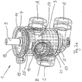
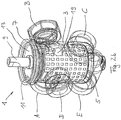
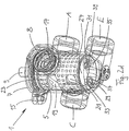
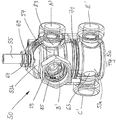
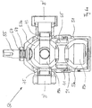
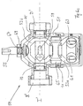
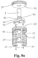
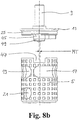
- FIGS. 1 to 3 and 8a , 8b a first preferred embodiment of the multi-way mixing valve 1 according to the invention is shown, wherein Fig. 1 shows a perspective overall view that Figures 2a to 2d show partially transparent perspective representations and in Fig. 3 a cross-sectional view is shown. In Figure 8a , 8b an exploded view of the interaction of certain parts is shown.
- the multi-way mixing valve 1 has an essentially hollow-cylindrical housing 3 on which five different connections A, B, C, D, E are arranged.
- a switching element 5 is provided, which is also designed as a hollow cylinder.
- a collar 7 is provided on the housing 3, on which a cover element 13 held by means of a snap ring 11 is arranged, a drive shaft 9 for actuating the switching element 5 being passed through the cover element 13.
- the housing 3 also has a cantilevered screw connection receptacle 15 on which the anti-rotation device (not shown) of an actuator (not shown) connected to the drive shaft 9 is arranged. This provides a rigid connection that prevents the actuator from turning around its own adjusting axis.
- the switching element 5 has different flow channels 17, 19, 21, 29, 31 which are arranged to correspond to the connections A, B, C, D, E.
- the three first connections A, B, D and the flow channels 17, 19 corresponding to them are formed in a first switching plane I.
- the connection A is arranged centrally and the connections D and B are arranged offset by 90 ° counterclockwise or clockwise.
- the associated flow channels 17, 19 are designed as elongated holes in the switching element 5 and each extend over an angular range of 90 ° or 45 °, so that either the connections A and B or the connections B and D can be connected to one another.
- the height or the outer radii of the elongated hole flow channels 17, 19 correspond to the respective inner diameters of the connections A, B, D, which are in contact with the switching element 5.
- the elongated hole flow channel 17 extends over a circumferential angle range of 90 ° and the elongated hole flow channel 19 extends over a circumferential angle range of 45 °.
- a web is provided between the two slot flow channels 17, 19, which is only made so wide that it structurally supports the switching element 5 and does not yet impair the flow.
- a single elongated hole flow channel could also be used can be provided, which then extends over a circumferential angle range of approximately 135 °.
- first of the second connections connection C
- connection C is arranged together with the flow channel 21 communicating therewith.
- This flow channel 21 is designed as a circular opening in the switching element 5, the diameter of which is dimensioned such that it corresponds to the inner diameter of the connection C on the switching element 5.
- the flow channel 21 is arranged below the flow channel 19 with respect to the longitudinal axis L of the multi-way mixing valve 1, the outer radius of the elongated flow channel 19 facing the elongated hole flow channel 17 being aligned with the circumference of the flow channel 21 with respect to the longitudinal axis L.
- two oppositely arranged flow channels 29, 31 are provided which, with corresponding connection openings 33, 35 of the connection E, form a third circuit level.
- the diameters of the flow channels 29, 31 in turn match the diameters of the associated connection openings 33, 35, the respective sum of the opening areas of the flow channels 29, 31 or the connection openings 33, 35 being identical to the opening area of the flow channel 21 or the connections A, B, C, D and the opening area inscribed in the elongated hole flow channels 17, 19.
- the diameters of the flow channels 29, 31 are kept in such a way that there are intermediate positions of the switching element 5 in which communication between the flow channels 29, 31 and the connection openings 33, 35 is prevented.
- the actuating element 5 is provided with an EPDM-coated surface and additionally has friction-reducing square depressions 23 arranged in a grid pattern.
- sealing rings (not shown) surrounding the connections A, B, C, D are provided and, with respect to the connection E, the flow channels 29, 31 are in the base 27 of the switching element 5 surrounded by sealing rings 37, 39.
- a sealing ring 25 is provided for sealing the housing 3 and the passage of the drive shaft 9 is sealed in a fluid-tight manner from the cover element 13 by means of sealing rings 41, 43.
- a position of the switching element 5 relative to the housing 3 is shown, with which a mixed state is realized in which the connections A and B of the first switching level I communicate with each other and the remaining connections C, D, E are blocked, i.e. in no fluid communication stand (this represents the mixed state a)).
- the further mixed states b) to f) can then be passed through successively, the mixed states a) to e) within one rotation 90 ° and mixed state f), i.e. the complete communication between ports D and E, in which port D is open at most with flow channel 19 and connection openings 33, 35 are open at most with corresponding flow channels 29, 31, after 135 ° is reached.
- a mechanical stop for example on the drive shaft 9 or a limit switch (not shown)
- Drive motor (not shown)
- a corresponding mechanical stop for example on the drive shaft 9 or a corresponding limit switch (not shown) of a drive motor (not shown) can also be provided to prevent further clockwise rotation beyond the mixed state f).
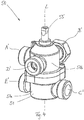
- FIG. 4 a second preferred embodiment of the multi-way mixing valve 50 according to the invention is shown in different views. It shows Fig. 4 a perspective overall view that Figures 5a to 5c show partially transparent perspective views and the Figures 6a to 6c show various sectional views of this multi-way mixing valve 50.
- this multi-way mixing valve 50 has a housing 51 which is constructed in two parts with a lower housing part 51a and an upper housing part 51b.
- an adjusting element 53 is arranged, which consists of two spherical half-shells 53a, 53b, which are connected with the aid of the connecting element 65 such that the interior spaces 89a, 89b of the spherical half-shells 53a, 53b are in fluid communication.
- a drive shaft 55 for driving the switching element 53 is passed through the housing 51.
- mechanical stops for example on the drive shaft 55 or a limit switch (not shown) of a drive motor (not shown), can be provided.
- two flow channels 57, 59 designed as elongated holes are formed, which in turn each extend over an angular range of 90 ° and 45 °.
- the elongated hole flow channel 59 is formed with a smaller height compared to the elongated hole flow channel 57. This dimensioning is advantageous if it is to be expected that the heating medium guided through the elongated hole flow channel 59 has a higher medium temperature, so that only relatively small amounts of hot medium and larger amounts of cold medium are then required to produce the warm mixture.
- two circular flow channels 61, 63 are provided, which are arranged offset from one another by an angle of 90 °.
- the one flow channel 63 is in turn aligned with the outer radius of the elongated flow channel 59 facing the elongated hole flow channel 57 in relation to the longitudinal axis L ′.
- each connection A ', B', C ', D', E ' has a cylinder insert 83 which is fastened with the aid of a snap ring 58 and is sealed with respect to the housing 51 by means of the sealing rings 73, 75, 77, 79, 81 is.
- This cylinder inserts 83 for example from PTFE are made, lie sealingly against the respective spherical half-shells 53a, 53b and prevent an undesired transfer of fluid from the respective connection A ', B', C ', D', E 'into another connection A', B ', C ', D', E '. Fluid is located in the space 91 formed between the housing 51 and the switching element 53.
- this multi-way mixing valve 50 has two switching levels I ', II', the connections A ', B', D 'and the corresponding elongated hole flow channels 57, 59 being in the first switching level, while the second switching level is II 'the connections C', E 'and the corresponding flow channels 61, 63 are located.
- the exact dimensioning of the multi-way mixing valves 1, 50 depends on the respective line classes and the desired media throughputs and can be adapted accordingly by a person skilled in the art.
- Fig. 7 the mixed states a) to f) of the multi-way mixing valve 1, 50 according to the invention are shown schematically. These mixed states a) to f) are passed through by successively turning the switching element 5, 53 clockwise from the starting position a) to the end position f). This adjustment by means of the drive shafts 9, 55 takes place either manually, or a corresponding drive motor (not shown) must be provided. As already shown above, there is no complete rotation of the switching element 5, 53 with respect to the housing 3, 51, but instead, starting from a stop position in mixed state a), a rotation over an angular range of 135 ° to the stop position in mixed state f).
- connections that are in direct fluid communication with one another are identified by the triangles filled in black.
- Fig. 7 only the connections A, B, C, D, E of the multi-way mixing valve 1 are given, but for the sake of clarity not those A ', B', C ', D', E 'of the multi-way mixing valve 50.
- ports A, B and C are connected to one another, so that heat medium flows from port A to port B and, in addition, port B is also supplied with heat medium from port C.
- the media flow from connection B is thus the sum of the media flows from connections A and C, so the underfloor heating 107 is successively supplied with heat medium from the unmixed heating circuit with the radiator heater 103, whereby an external media admixture takes place.
- This state b) is used when the return temperature of the unmixed heating circuit is higher than the return temperature of the mixed heating circuit.
- mixed state c) only ports B and C are in communication, which means that heat medium flows from port C to port B.
- heat medium from the return of the radiator heater 105 is mixed into connection B via the node 109.
- This state c) is used when the return temperature of the unmixed heating circuit matches the flow temperature of the mixed heating circuit.
- ports B, C and D are in fluid communication with one another.
- heat medium flows from port C to port B and also from port D to port B.
- port B there is a mixed amount of the media flows fed in from ports C and D.
- This state d) is used when the return temperature of the unmixed heating circuit is less than the flow temperature of the mixed heating circuit, so that heat medium from the heat source 101 is mixed into the mixed heating circuit.
- a commonly used interconnection is shown on the right-hand side with which the same mixed states can be implemented.
- the Alternative embodiment without five-way mixing valve 1 requires two three-way mixing valves 130, 130a and at least the additional two circulating pumps 131, 133 and corresponding controls are necessary, as a result of which this circuit is very complicated and costly.
- the circulating pump 113 is sufficient to supply the unmixed heating circuit 103, the mixed heating circuit 107 or the hot water storage heating circuit 103 with heat transfer medium as required.
- the additional provision of shut-off valves in this hot water storage heating circuit 103 is not necessary.
- the multi-way mixing valve 1, 50 according to the invention can also be used advantageously for numerous other applications, for example the interconnection of a mixed heating circuit with a heat source and a buffer store (not shown).
Landscapes
- Engineering & Computer Science (AREA)
- General Engineering & Computer Science (AREA)
- Mechanical Engineering (AREA)
- Physics & Mathematics (AREA)
- Thermal Sciences (AREA)
- Chemical & Material Sciences (AREA)
- Combustion & Propulsion (AREA)
- Multiple-Way Valves (AREA)
Claims (11)
- Vanne mélangeuse multivoie (1 ; 50) pour systèmes de préparation d'eau chaude et/ou de chauffage, comprenant un boîtier de vanne (3 ; 51) et au moins cinq raccordements (A, B, C, D, E), qui peuvent être reliés les uns aux autres par le biais d'un élément de commutation (5 ; 53) monté dans le boîtier de vanne (3 ; 51), qui comporte des canaux d'écoulement (17, 19, 21, 29, 31 ; 57, 59, 61, 63), trois premiers raccordements (A, B, D) étant associés à un premier plan de commutation (I; I') de l'élément de commutation (5 ; 53) et deux deuxièmes raccordements (C, E) étant associés à un ou plusieurs deuxièmes plans de commutation (II ; II') de l'élément de commutation (5 ; 53) qui sont différents du premier plan de commutation (I ; I'), caractérisée en ce que
l'élément de commutation (5 ; 53) est conçu en lien avec les raccordements (A, B, C, D, E) de telle manière que, en tournant l'élément de commutation (5 ; 53) sur au moins une plage angulaire d'un axe de rotation (L; L'), les états de mélange suivants peuvent être commandés, de préférence commandés successivement :a) raccordement d'un premier (A) des premiers raccordements à un deuxième (B) des premiers raccordements,b) raccordement simultané du premier (A) des premiers raccordements au deuxième (B) des premiers raccordements et d'un premier (C) des deuxièmes raccordements au deuxième (B) des premiers raccordements,c) raccordement du premier (C) des deuxièmes raccordements au deuxième (B) des premiers raccordements,d) raccordement simultané du premier (C) des deuxièmes raccordements au deuxième (B) des premiers raccordements et d'un troisième (D) des premiers raccordements au deuxième (B) des premiers raccordements,e) raccordement du troisième (D) des premiers raccordements au deuxième (B) des premiers raccordements etf) raccordement du troisième (D) des premiers raccordements à un deuxième (E) des deuxièmes raccordements, une première position de butée étant réalisée pour l'élément de commutation (5 ; 53), dans laquelle on a l'état de mélange a), et/ou une deuxième position de butée étant réalisée, dans laquelle on a l'état de mélange f), moyennant quoi un raccordement de trois dissipateurs thermiques à une source de chaleur peut être obtenu, l'état de mélange f) permettant de réaliser une priorité de commutation pour alimenter exclusivement un accumulateur de chaleur, cas dans lequel aucun ajout n'est effectué dans les autres dissipateurs thermiques. - Vanne mélangeuse multivoie (1 ; 50) selon la revendication 1, caractérisée en ce que les trois premiers raccordements (A, B, D) sont disposés dans le premier plan de commutation (I ; I') avec un décalage entre eux de 90°.
- Vanne mélangeuse multivoie (1; 50) selon la revendication 1 ou 2, caractérisée en ce qu'au moins un des deuxièmes raccordements (C) n'est pas aligné avec un des trois premiers raccordements (A, B, D) par rapport à la projection du premier plan de commutation (I ; I'), et est en particulier disposé avec un décalage de 90° par rapport aux trois premiers raccordements (A, B, D), et/ou en ce que les deuxièmes raccordements (61, 63) sont disposés dans un même deuxième plan de commutation (II') de l'élément de commutation (53).
- Vanne mélangeuse multivoie (1) selon l'une des revendications, précédentes, caractérisée en ce que l'élément de commutation (5) comporte, dans certaines zones, des creux (23) par rapport au boîtier de vanne (3), qui sont disposés de préférence selon un motif et qui sont réalisés en particulier en forme de parallélogrammes et/ou en ce que l'élément de commutation (5) comporte un revêtement pour réduire les frottements, le revêtement comportant de préférence un caoutchouc synthétique, et étant réalisé en particulier sous la forme d'un revêtement en EPDM.
- Vanne mélangeuse multivoie (1 ; 50) selon l'une des revendications précédentes, caractérisée en ce qu'au moins deux premiers canaux d'écoulement (17, 19 ; 57, 59) sont associés aux trois premiers raccordements (A, B, D), les deux canaux d'écoulement (17, 19 ; 57, 59) étant conçus de telle sorte qu'ils peuvent respectivement recouvrir simultanément deux des trois premiers raccordements (A, B, D), et/ou en ce que l'élément de commutation (5 ; 53) est conçu sous la forme d'un élément cylindrique creux fermé le cas échéant d'un ou des deux côtés ou sous la forme de deux éléments (53a, 53b) de type coque sphérique raccordés l'un à l'autre.
- Vanne mélangeuse multivoie (5) selon l'une des revendications précédentes, caractérisée en ce que deux deuxièmes canaux d'écoulement (29, 31) sont associés à au moins un raccordement (E), le raccordement (E) communiquant, au moins dans une position de commutation de l'élément de commutation (5), simultanément avec les deux canaux d'écoulement (29, 31), les deux canaux d'écoulement (29, 31) étant de préférence disposés dans une surface frontale de l'élément de commutation (5).
- Vanne mélangeuse multivoie (5) selon la revendication 6, caractérisée en ce que les deux canaux d'écoulement (29, 31) présentent au total au moins la même aire de section transversale que l'aire de section transversale d'au moins un des premiers raccordements (A, B, D), qui présentent de préférence respectivement la même aire de section transversale.
- Vanne mélangeuse multivoie (1 ; 50) selon l'une des revendications précédentes, caractérisée en ce qu'une première position de butée est réalisée pour l'élément de commutation (5 ; 53), dans laquelle on a la position a), et/ou une deuxième position de butée est réalisée, dans laquelle on a la position f), la première et la deuxième position de butée étant en particulier réalisées par le biais d'interrupteurs de fin de course d'un moteur entraînant l'élément de commutation (5 ; 53).
- Vanne mélangeuse multivoie (1 ; 50) selon la revendication 8, caractérisée en ce que l'angle de rotation de l'élément de commutation (5 ; 53) entre les états de mélange a) et f) est de 135°, et un angle de rotation entre les états de mélange a) et e) de 90° et un angle de rotation entre les états de mélange e) et f) de 45° étant de préférence prévus.
- Procédé de commande temporelle du raccordement de cinq raccordements (A, B, C, D, E) conducteurs de fluide les uns aux autres dans une vanne mélangeuse multivoie (1 ; 50) pour systèmes de préparation d'eau chaude et/ou de chauffage, la vanne mélangeuse multivoie (1 ; 50) possédant un boîtier de vanne (3 ; 51) et au moins cinq raccordements (A, B, C, D, E), qui peuvent être reliés les uns aux autres par le biais d'un élément de commutation (5 ; 53) monté dans le boîtier de vanne (3 ; 51), qui comporte des canaux d'écoulement (17, 19, 21, 29, 31; 57, 59, 61, 63), trois premiers raccordements (A, B, D) étant associés à un premier plan de commutation (I; I') de l'élément de commutation (5 ; 53) et deux deuxièmes raccordements (C, E) étant associés à un ou plusieurs deuxièmes plans de commutation (II ; II') de l'élément de commutation (5 ; 53) qui sont différents du premier plan de commutation (I ; I'), caractérisé par les étapes possibles suivantes :h) raccordement d'un premier (A) des premiers raccordements à un deuxième (B) des premiers raccordements,i) raccordement simultané du premier (A) des premiers raccordements au deuxième (B) des premiers raccordements et d'un premier (C) des deuxièmes raccordements au deuxième (B) des premiers raccordements,k) raccordement du premier (C) des deuxièmes raccordements au deuxième (B) des premiers raccordements,I) raccordement simultané du premier (C) des deuxièmes raccordements au deuxième (B) des premiers raccordements et d'un troisième (D) des premiers raccordements au deuxième (B) des premiers raccordements,m) raccordement du troisième (D) des premiers raccordements au deuxième (B) des premiers raccordements etn) raccordement du troisième (D) des premiers raccordements à un deuxième (E) des deuxièmes raccordements, une première position de butée étant réalisée pour l'élément de commutation (5 ; 53), dans laquelle on a l'étape h), et/ou une deuxième position de butée étant réalisée, dans laquelle on a l'étape n), moyennant quoi un raccordement de trois dissipateurs thermiques à une source de chaleur peut être obtenu, l'étape n) permettant de réaliser une priorité de commutation pour alimenter exclusivement un accumulateur de chaleur, cas dans lequel aucun ajout n'est effectué dans les autres dissipateurs thermiques.
- Procédé selon la revendication 10, caractérisé en ce que la vanne mélangeuse multivoie (1; 50) est réalisée selon l'une des revendications 1 à 9.
Applications Claiming Priority (2)
| Application Number | Priority Date | Filing Date | Title |
|---|---|---|---|
| DE102012024585.8A DE102012024585A1 (de) | 2012-12-17 | 2012-12-17 | Mehrwegemischventil und Verfahren zum zeitlichen Steuern eines Mehrwegemischventils |
| PCT/EP2013/003787 WO2014095021A1 (fr) | 2012-12-17 | 2013-12-16 | Vanne mélangeuse multivoie et procédé de commande temporelle d'une vanne mélangeuse multivoie |
Publications (2)
| Publication Number | Publication Date |
|---|---|
| EP2932142A1 EP2932142A1 (fr) | 2015-10-21 |
| EP2932142B1 true EP2932142B1 (fr) | 2021-06-09 |
Family
ID=49911452
Family Applications (1)
| Application Number | Title | Priority Date | Filing Date |
|---|---|---|---|
| EP13815380.4A Active EP2932142B1 (fr) | 2012-12-17 | 2013-12-16 | Vanne mélangeuse multivoie et procédé de commande temporelle d'une vanne mélangeuse multivoie |
Country Status (5)
| Country | Link |
|---|---|
| EP (1) | EP2932142B1 (fr) |
| CN (1) | CN105190137A (fr) |
| DE (1) | DE102012024585A1 (fr) |
| EA (1) | EA201591146A1 (fr) |
| WO (1) | WO2014095021A1 (fr) |
Cited By (3)
| Publication number | Priority date | Publication date | Assignee | Title |
|---|---|---|---|---|
| DE102022114176A1 (de) | 2022-06-03 | 2023-12-14 | Schaeffler Technologies AG & Co. KG | Thermomanagementmodul und Drehschieberventil mit Drehschieber mit schneidungsfrei überkreuzten Kanälen in einer Axialebene sowie dazu axialversetztem Zusatzkanal |
| US20240110630A1 (en) * | 2021-06-14 | 2024-04-04 | HELLA GmbH & Co. KGaA | Multiway valve for an electric vehicle, thermal management system, and method for operating a thermal management system |
| EP4717952A1 (fr) * | 2024-09-25 | 2026-04-01 | Aisin Corporation | Collecteur |
Families Citing this family (4)
| Publication number | Priority date | Publication date | Assignee | Title |
|---|---|---|---|---|
| DE102009035349B4 (de) | 2009-07-30 | 2018-06-28 | BorgWarner Esslingen GmbH | Steuervorrichtung für den Kühlmittelfluss im Kühlkreislauf einer Brennkraftmaschine |
| WO2016055127A1 (fr) * | 2014-10-10 | 2016-04-14 | Solabcool B.V. | Système de refroidissement, cuve de réacteur et vanne rotative |
| CN107559459B (zh) * | 2017-09-11 | 2024-04-12 | 南宁宇立仪器有限公司 | 一种电动伺服阀 |
| CN114413031B (zh) * | 2021-12-24 | 2024-09-27 | 成都万友滤机有限公司 | 一种集成可比例调节的多通阀 |
Family Cites Families (8)
| Publication number | Priority date | Publication date | Assignee | Title |
|---|---|---|---|---|
| US5927330A (en) * | 1996-02-06 | 1999-07-27 | Oil States Industries | Modular, high-volume, rotary selector valve |
| DE19614868A1 (de) * | 1996-04-16 | 1997-10-23 | Zahnradfabrik Friedrichshafen | Ventilschieber für eine elektro-hydraulische Getriebesteuerung eines Automatgetriebes |
| DE10214242B4 (de) | 2001-03-26 | 2014-10-23 | Hg Baunach Gmbh & Co Kg | Mehrwegemischventil und Verfahren zu seiner zeitlichen Steuerung |
| DE10242727B4 (de) | 2002-09-13 | 2008-01-10 | First, Franc | Ventil |
| WO2006109639A1 (fr) * | 2005-04-08 | 2006-10-19 | Ihara Science Corporation | Valve de collecteur et dispositif psa possédant ladite valve |
| DE102007009194B3 (de) * | 2007-02-26 | 2008-09-25 | Kioto Clear Energy Ag | Mehrwegeventil |
| DE102008013124A1 (de) | 2008-03-07 | 2009-09-10 | Meibes System-Technik Gmbh | Mehrkreisige Heizungsanlage |
| EP2397777B1 (fr) * | 2010-06-19 | 2016-08-03 | Grundfos Management A/S | Unité de boîtier pour une installation de chauffage |
-
2012
- 2012-12-17 DE DE102012024585.8A patent/DE102012024585A1/de not_active Withdrawn
-
2013
- 2013-12-16 EA EA201591146A patent/EA201591146A1/ru unknown
- 2013-12-16 WO PCT/EP2013/003787 patent/WO2014095021A1/fr not_active Ceased
- 2013-12-16 EP EP13815380.4A patent/EP2932142B1/fr active Active
- 2013-12-16 CN CN201380071797.8A patent/CN105190137A/zh active Pending
Non-Patent Citations (1)
| Title |
|---|
| None * |
Cited By (3)
| Publication number | Priority date | Publication date | Assignee | Title |
|---|---|---|---|---|
| US20240110630A1 (en) * | 2021-06-14 | 2024-04-04 | HELLA GmbH & Co. KGaA | Multiway valve for an electric vehicle, thermal management system, and method for operating a thermal management system |
| DE102022114176A1 (de) | 2022-06-03 | 2023-12-14 | Schaeffler Technologies AG & Co. KG | Thermomanagementmodul und Drehschieberventil mit Drehschieber mit schneidungsfrei überkreuzten Kanälen in einer Axialebene sowie dazu axialversetztem Zusatzkanal |
| EP4717952A1 (fr) * | 2024-09-25 | 2026-04-01 | Aisin Corporation | Collecteur |
Also Published As
| Publication number | Publication date |
|---|---|
| WO2014095021A1 (fr) | 2014-06-26 |
| EP2932142A1 (fr) | 2015-10-21 |
| EA201591146A1 (ru) | 2015-11-30 |
| CN105190137A (zh) | 2015-12-23 |
| DE102012024585A1 (de) | 2014-06-18 |
Similar Documents
| Publication | Publication Date | Title |
|---|---|---|
| EP2932142B1 (fr) | Vanne mélangeuse multivoie et procédé de commande temporelle d'une vanne mélangeuse multivoie | |
| EP0162342B1 (fr) | Insert de contrôle pour mélangeur sanitaire | |
| DE102019114645A1 (de) | Mehrwege-Scheibenventilanordnung | |
| DE60128717T2 (de) | Vierwegeventil | |
| DE202014102389U1 (de) | Modulares Ventilsystem | |
| WO2021250176A1 (fr) | Distributeur et cage pour un distributeur | |
| DE102021110106B4 (de) | Multiventil | |
| EP3232102A1 (fr) | Vanne rotative | |
| DE2548308A1 (de) | Doppel-koaxialventil und damit ausgestattete filteraggregate und hydrostatische systeme | |
| EP2932160B1 (fr) | Installation de chauffage et/ou de refroidissement à plusieurs circuits à vanne mélangeuse à plusieurs voies et dispositif de commande et/ou de régulation d'une installation de chauffage et/ou de refroidissement à plusieurs circuits | |
| DE102023117369A1 (de) | Kugelventil einer Kältemittelventileinrichtung für eine Klimaanlage | |
| DE69924647T2 (de) | Plattenwärmetauscher mit integriertem ventil | |
| DE102016000317A1 (de) | Mehrwegeventil für ein Heiz-und Kühlsystem eines Fahrzeugs | |
| DE102005061297B4 (de) | Kugelventil | |
| EP2633212B1 (fr) | Distributeur | |
| EP1614944B1 (fr) | Vanne à voies multiples ou vanne de distribution | |
| EP3608597B1 (fr) | Armature de raccordement permettant de commander le sens d'écoulement d'un milieu de chauffage dans un radiateur | |
| EP1710518B1 (fr) | Dispositif de raccordement | |
| EP3376082B1 (fr) | Dispositif de soupape | |
| DE102005062592A1 (de) | Einrichtung zum temperaturabhängigen Steuern von Strömungswegen | |
| EP1515073B1 (fr) | Vanne à voies multiples | |
| DE102024001819A1 (de) | Fluidspeicher mit einem schnell und leicht verstellbaren Drei- oder Mehrwegefluidspeicherventil | |
| DE112023000568T5 (de) | Planetenfluidsteuerventil | |
| DE102024001816A1 (de) | Fluidspeicher mit einem schnell und leicht verstellbaren Drei- oder Mehrwegefluidspeicherventil | |
| DE8034166U1 (de) | Ventil-baukastenanordnung |
Legal Events
| Date | Code | Title | Description |
|---|---|---|---|
| PUAI | Public reference made under article 153(3) epc to a published international application that has entered the european phase |
Free format text: ORIGINAL CODE: 0009012 |
|
| 17P | Request for examination filed |
Effective date: 20150716 |
|
| AK | Designated contracting states |
Kind code of ref document: A1 Designated state(s): AL AT BE BG CH CY CZ DE DK EE ES FI FR GB GR HR HU IE IS IT LI LT LU LV MC MK MT NL NO PL PT RO RS SE SI SK SM TR |
|
| AX | Request for extension of the european patent |
Extension state: BA ME |
|
| DAX | Request for extension of the european patent (deleted) | ||
| STAA | Information on the status of an ep patent application or granted ep patent |
Free format text: STATUS: EXAMINATION IS IN PROGRESS |
|
| 17Q | First examination report despatched |
Effective date: 20181113 |
|
| GRAP | Despatch of communication of intention to grant a patent |
Free format text: ORIGINAL CODE: EPIDOSNIGR1 |
|
| STAA | Information on the status of an ep patent application or granted ep patent |
Free format text: STATUS: GRANT OF PATENT IS INTENDED |
|
| INTG | Intention to grant announced |
Effective date: 20210112 |
|
| GRAS | Grant fee paid |
Free format text: ORIGINAL CODE: EPIDOSNIGR3 |
|
| GRAA | (expected) grant |
Free format text: ORIGINAL CODE: 0009210 |
|
| STAA | Information on the status of an ep patent application or granted ep patent |
Free format text: STATUS: THE PATENT HAS BEEN GRANTED |
|
| AK | Designated contracting states |
Kind code of ref document: B1 Designated state(s): AL AT BE BG CH CY CZ DE DK EE ES FI FR GB GR HR HU IE IS IT LI LT LU LV MC MK MT NL NO PL PT RO RS SE SI SK SM TR |
|
| REG | Reference to a national code |
Ref country code: GB Ref legal event code: FG4D Free format text: NOT ENGLISH |
|
| REG | Reference to a national code |
Ref country code: CH Ref legal event code: EP Ref country code: AT Ref legal event code: REF Ref document number: 1400781 Country of ref document: AT Kind code of ref document: T Effective date: 20210615 |
|
| REG | Reference to a national code |
Ref country code: DE Ref legal event code: R096 Ref document number: 502013015771 Country of ref document: DE |
|
| REG | Reference to a national code |
Ref country code: IE Ref legal event code: FG4D Free format text: LANGUAGE OF EP DOCUMENT: GERMAN |
|
| REG | Reference to a national code |
Ref country code: LT Ref legal event code: MG9D |
|
| PG25 | Lapsed in a contracting state [announced via postgrant information from national office to epo] |
Ref country code: HR Free format text: LAPSE BECAUSE OF FAILURE TO SUBMIT A TRANSLATION OF THE DESCRIPTION OR TO PAY THE FEE WITHIN THE PRESCRIBED TIME-LIMIT Effective date: 20210609 Ref country code: BG Free format text: LAPSE BECAUSE OF FAILURE TO SUBMIT A TRANSLATION OF THE DESCRIPTION OR TO PAY THE FEE WITHIN THE PRESCRIBED TIME-LIMIT Effective date: 20210909 Ref country code: FI Free format text: LAPSE BECAUSE OF FAILURE TO SUBMIT A TRANSLATION OF THE DESCRIPTION OR TO PAY THE FEE WITHIN THE PRESCRIBED TIME-LIMIT Effective date: 20210609 Ref country code: LT Free format text: LAPSE BECAUSE OF FAILURE TO SUBMIT A TRANSLATION OF THE DESCRIPTION OR TO PAY THE FEE WITHIN THE PRESCRIBED TIME-LIMIT Effective date: 20210609 |
|
| REG | Reference to a national code |
Ref country code: NL Ref legal event code: MP Effective date: 20210609 |
|
| PG25 | Lapsed in a contracting state [announced via postgrant information from national office to epo] |
Ref country code: LV Free format text: LAPSE BECAUSE OF FAILURE TO SUBMIT A TRANSLATION OF THE DESCRIPTION OR TO PAY THE FEE WITHIN THE PRESCRIBED TIME-LIMIT Effective date: 20210609 Ref country code: GR Free format text: LAPSE BECAUSE OF FAILURE TO SUBMIT A TRANSLATION OF THE DESCRIPTION OR TO PAY THE FEE WITHIN THE PRESCRIBED TIME-LIMIT Effective date: 20210910 Ref country code: RS Free format text: LAPSE BECAUSE OF FAILURE TO SUBMIT A TRANSLATION OF THE DESCRIPTION OR TO PAY THE FEE WITHIN THE PRESCRIBED TIME-LIMIT Effective date: 20210609 Ref country code: SE Free format text: LAPSE BECAUSE OF FAILURE TO SUBMIT A TRANSLATION OF THE DESCRIPTION OR TO PAY THE FEE WITHIN THE PRESCRIBED TIME-LIMIT Effective date: 20210609 Ref country code: NO Free format text: LAPSE BECAUSE OF FAILURE TO SUBMIT A TRANSLATION OF THE DESCRIPTION OR TO PAY THE FEE WITHIN THE PRESCRIBED TIME-LIMIT Effective date: 20210909 |
|
| PG25 | Lapsed in a contracting state [announced via postgrant information from national office to epo] |
Ref country code: EE Free format text: LAPSE BECAUSE OF FAILURE TO SUBMIT A TRANSLATION OF THE DESCRIPTION OR TO PAY THE FEE WITHIN THE PRESCRIBED TIME-LIMIT Effective date: 20210609 Ref country code: CZ Free format text: LAPSE BECAUSE OF FAILURE TO SUBMIT A TRANSLATION OF THE DESCRIPTION OR TO PAY THE FEE WITHIN THE PRESCRIBED TIME-LIMIT Effective date: 20210609 Ref country code: SM Free format text: LAPSE BECAUSE OF FAILURE TO SUBMIT A TRANSLATION OF THE DESCRIPTION OR TO PAY THE FEE WITHIN THE PRESCRIBED TIME-LIMIT Effective date: 20210609 Ref country code: SK Free format text: LAPSE BECAUSE OF FAILURE TO SUBMIT A TRANSLATION OF THE DESCRIPTION OR TO PAY THE FEE WITHIN THE PRESCRIBED TIME-LIMIT Effective date: 20210609 Ref country code: PT Free format text: LAPSE BECAUSE OF FAILURE TO SUBMIT A TRANSLATION OF THE DESCRIPTION OR TO PAY THE FEE WITHIN THE PRESCRIBED TIME-LIMIT Effective date: 20211011 Ref country code: NL Free format text: LAPSE BECAUSE OF FAILURE TO SUBMIT A TRANSLATION OF THE DESCRIPTION OR TO PAY THE FEE WITHIN THE PRESCRIBED TIME-LIMIT Effective date: 20210609 Ref country code: RO Free format text: LAPSE BECAUSE OF FAILURE TO SUBMIT A TRANSLATION OF THE DESCRIPTION OR TO PAY THE FEE WITHIN THE PRESCRIBED TIME-LIMIT Effective date: 20210609 Ref country code: ES Free format text: LAPSE BECAUSE OF FAILURE TO SUBMIT A TRANSLATION OF THE DESCRIPTION OR TO PAY THE FEE WITHIN THE PRESCRIBED TIME-LIMIT Effective date: 20210609 |
|
| PG25 | Lapsed in a contracting state [announced via postgrant information from national office to epo] |
Ref country code: PL Free format text: LAPSE BECAUSE OF FAILURE TO SUBMIT A TRANSLATION OF THE DESCRIPTION OR TO PAY THE FEE WITHIN THE PRESCRIBED TIME-LIMIT Effective date: 20210609 |
|
| REG | Reference to a national code |
Ref country code: DE Ref legal event code: R097 Ref document number: 502013015771 Country of ref document: DE |
|
| PLBE | No opposition filed within time limit |
Free format text: ORIGINAL CODE: 0009261 |
|
| STAA | Information on the status of an ep patent application or granted ep patent |
Free format text: STATUS: NO OPPOSITION FILED WITHIN TIME LIMIT |
|
| PG25 | Lapsed in a contracting state [announced via postgrant information from national office to epo] |
Ref country code: DK Free format text: LAPSE BECAUSE OF FAILURE TO SUBMIT A TRANSLATION OF THE DESCRIPTION OR TO PAY THE FEE WITHIN THE PRESCRIBED TIME-LIMIT Effective date: 20210609 |
|
| 26N | No opposition filed |
Effective date: 20220310 |
|
| PG25 | Lapsed in a contracting state [announced via postgrant information from national office to epo] |
Ref country code: AL Free format text: LAPSE BECAUSE OF FAILURE TO SUBMIT A TRANSLATION OF THE DESCRIPTION OR TO PAY THE FEE WITHIN THE PRESCRIBED TIME-LIMIT Effective date: 20210609 |
|
| PG25 | Lapsed in a contracting state [announced via postgrant information from national office to epo] |
Ref country code: MC Free format text: LAPSE BECAUSE OF FAILURE TO SUBMIT A TRANSLATION OF THE DESCRIPTION OR TO PAY THE FEE WITHIN THE PRESCRIBED TIME-LIMIT Effective date: 20210609 Ref country code: IT Free format text: LAPSE BECAUSE OF FAILURE TO SUBMIT A TRANSLATION OF THE DESCRIPTION OR TO PAY THE FEE WITHIN THE PRESCRIBED TIME-LIMIT Effective date: 20210609 |
|
| REG | Reference to a national code |
Ref country code: CH Ref legal event code: PL |
|
| GBPC | Gb: european patent ceased through non-payment of renewal fee |
Effective date: 20211216 |
|
| REG | Reference to a national code |
Ref country code: BE Ref legal event code: MM Effective date: 20211231 |
|
| PG25 | Lapsed in a contracting state [announced via postgrant information from national office to epo] |
Ref country code: LU Free format text: LAPSE BECAUSE OF NON-PAYMENT OF DUE FEES Effective date: 20211216 Ref country code: IE Free format text: LAPSE BECAUSE OF NON-PAYMENT OF DUE FEES Effective date: 20211216 Ref country code: GB Free format text: LAPSE BECAUSE OF NON-PAYMENT OF DUE FEES Effective date: 20211216 |
|
| PG25 | Lapsed in a contracting state [announced via postgrant information from national office to epo] |
Ref country code: FR Free format text: LAPSE BECAUSE OF NON-PAYMENT OF DUE FEES Effective date: 20211231 Ref country code: BE Free format text: LAPSE BECAUSE OF NON-PAYMENT OF DUE FEES Effective date: 20211231 |
|
| PG25 | Lapsed in a contracting state [announced via postgrant information from national office to epo] |
Ref country code: LI Free format text: LAPSE BECAUSE OF NON-PAYMENT OF DUE FEES Effective date: 20211231 Ref country code: CH Free format text: LAPSE BECAUSE OF NON-PAYMENT OF DUE FEES Effective date: 20211231 |
|
| REG | Reference to a national code |
Ref country code: AT Ref legal event code: MM01 Ref document number: 1400781 Country of ref document: AT Kind code of ref document: T Effective date: 20211216 |
|
| PG25 | Lapsed in a contracting state [announced via postgrant information from national office to epo] |
Ref country code: AT Free format text: LAPSE BECAUSE OF NON-PAYMENT OF DUE FEES Effective date: 20211216 |
|
| PG25 | Lapsed in a contracting state [announced via postgrant information from national office to epo] |
Ref country code: HU Free format text: LAPSE BECAUSE OF FAILURE TO SUBMIT A TRANSLATION OF THE DESCRIPTION OR TO PAY THE FEE WITHIN THE PRESCRIBED TIME-LIMIT; INVALID AB INITIO Effective date: 20131216 |
|
| PG25 | Lapsed in a contracting state [announced via postgrant information from national office to epo] |
Ref country code: CY Free format text: LAPSE BECAUSE OF FAILURE TO SUBMIT A TRANSLATION OF THE DESCRIPTION OR TO PAY THE FEE WITHIN THE PRESCRIBED TIME-LIMIT Effective date: 20210609 |
|
| P01 | Opt-out of the competence of the unified patent court (upc) registered |
Effective date: 20230527 |
|
| PG25 | Lapsed in a contracting state [announced via postgrant information from national office to epo] |
Ref country code: MK Free format text: LAPSE BECAUSE OF FAILURE TO SUBMIT A TRANSLATION OF THE DESCRIPTION OR TO PAY THE FEE WITHIN THE PRESCRIBED TIME-LIMIT Effective date: 20210609 |
|
| PG25 | Lapsed in a contracting state [announced via postgrant information from national office to epo] |
Ref country code: MT Free format text: LAPSE BECAUSE OF FAILURE TO SUBMIT A TRANSLATION OF THE DESCRIPTION OR TO PAY THE FEE WITHIN THE PRESCRIBED TIME-LIMIT Effective date: 20210609 |
|
| PG25 | Lapsed in a contracting state [announced via postgrant information from national office to epo] |
Ref country code: TR Free format text: LAPSE BECAUSE OF FAILURE TO SUBMIT A TRANSLATION OF THE DESCRIPTION OR TO PAY THE FEE WITHIN THE PRESCRIBED TIME-LIMIT Effective date: 20210609 |
|
| PGFP | Annual fee paid to national office [announced via postgrant information from national office to epo] |
Ref country code: DE Payment date: 20260219 Year of fee payment: 13 |