EP2932157B1 - Ensemble coupelle rotative oblongue pour chambres de combustion - Google Patents
Ensemble coupelle rotative oblongue pour chambres de combustion Download PDFInfo
- Publication number
- EP2932157B1 EP2932157B1 EP13865651.7A EP13865651A EP2932157B1 EP 2932157 B1 EP2932157 B1 EP 2932157B1 EP 13865651 A EP13865651 A EP 13865651A EP 2932157 B1 EP2932157 B1 EP 2932157B1
- Authority
- EP
- European Patent Office
- Prior art keywords
- swirler
- oblong
- air
- fuel
- shape
- Prior art date
- Legal status (The legal status is an assumption and is not a legal conclusion. Google has not performed a legal analysis and makes no representation as to the accuracy of the status listed.)
- Active
Links
Images

Classifications
-
- F—MECHANICAL ENGINEERING; LIGHTING; HEATING; WEAPONS; BLASTING
- F23—COMBUSTION APPARATUS; COMBUSTION PROCESSES
- F23R—GENERATING COMBUSTION PRODUCTS OF HIGH PRESSURE OR HIGH VELOCITY, e.g. GAS-TURBINE COMBUSTION CHAMBERS
- F23R3/00—Continuous combustion chambers using liquid or gaseous fuel
- F23R3/28—Continuous combustion chambers using liquid or gaseous fuel characterised by the fuel supply
-
- F—MECHANICAL ENGINEERING; LIGHTING; HEATING; WEAPONS; BLASTING
- F23—COMBUSTION APPARATUS; COMBUSTION PROCESSES
- F23R—GENERATING COMBUSTION PRODUCTS OF HIGH PRESSURE OR HIGH VELOCITY, e.g. GAS-TURBINE COMBUSTION CHAMBERS
- F23R3/00—Continuous combustion chambers using liquid or gaseous fuel
- F23R3/02—Continuous combustion chambers using liquid or gaseous fuel characterised by the air-flow or gas-flow configuration
- F23R3/04—Air inlet arrangements
- F23R3/10—Air inlet arrangements for primary air
-
- F—MECHANICAL ENGINEERING; LIGHTING; HEATING; WEAPONS; BLASTING
- F23—COMBUSTION APPARATUS; COMBUSTION PROCESSES
- F23R—GENERATING COMBUSTION PRODUCTS OF HIGH PRESSURE OR HIGH VELOCITY, e.g. GAS-TURBINE COMBUSTION CHAMBERS
- F23R3/00—Continuous combustion chambers using liquid or gaseous fuel
- F23R3/02—Continuous combustion chambers using liquid or gaseous fuel characterised by the air-flow or gas-flow configuration
- F23R3/04—Air inlet arrangements
- F23R3/10—Air inlet arrangements for primary air
- F23R3/12—Air inlet arrangements for primary air inducing a vortex
-
- F—MECHANICAL ENGINEERING; LIGHTING; HEATING; WEAPONS; BLASTING
- F23—COMBUSTION APPARATUS; COMBUSTION PROCESSES
- F23R—GENERATING COMBUSTION PRODUCTS OF HIGH PRESSURE OR HIGH VELOCITY, e.g. GAS-TURBINE COMBUSTION CHAMBERS
- F23R3/00—Continuous combustion chambers using liquid or gaseous fuel
- F23R3/02—Continuous combustion chambers using liquid or gaseous fuel characterised by the air-flow or gas-flow configuration
- F23R3/04—Air inlet arrangements
- F23R3/10—Air inlet arrangements for primary air
- F23R3/12—Air inlet arrangements for primary air inducing a vortex
- F23R3/14—Air inlet arrangements for primary air inducing a vortex by using swirl vanes
-
- F—MECHANICAL ENGINEERING; LIGHTING; HEATING; WEAPONS; BLASTING
- F23—COMBUSTION APPARATUS; COMBUSTION PROCESSES
- F23R—GENERATING COMBUSTION PRODUCTS OF HIGH PRESSURE OR HIGH VELOCITY, e.g. GAS-TURBINE COMBUSTION CHAMBERS
- F23R3/00—Continuous combustion chambers using liquid or gaseous fuel
- F23R3/28—Continuous combustion chambers using liquid or gaseous fuel characterised by the fuel supply
- F23R3/286—Continuous combustion chambers using liquid or gaseous fuel characterised by the fuel supply having fuel-air premixing devices
-
- F—MECHANICAL ENGINEERING; LIGHTING; HEATING; WEAPONS; BLASTING
- F05—INDEXING SCHEMES RELATING TO ENGINES OR PUMPS IN VARIOUS SUBCLASSES OF CLASSES F01-F04
- F05D—INDEXING SCHEME FOR ASPECTS RELATING TO NON-POSITIVE-DISPLACEMENT MACHINES OR ENGINES, GAS-TURBINES OR JET-PROPULSION PLANTS
- F05D2260/00—Function
- F05D2260/14—Preswirling
-
- Y—GENERAL TAGGING OF NEW TECHNOLOGICAL DEVELOPMENTS; GENERAL TAGGING OF CROSS-SECTIONAL TECHNOLOGIES SPANNING OVER SEVERAL SECTIONS OF THE IPC; TECHNICAL SUBJECTS COVERED BY FORMER USPC CROSS-REFERENCE ART COLLECTIONS [XRACs] AND DIGESTS
- Y02—TECHNOLOGIES OR APPLICATIONS FOR MITIGATION OR ADAPTATION AGAINST CLIMATE CHANGE
- Y02T—CLIMATE CHANGE MITIGATION TECHNOLOGIES RELATED TO TRANSPORTATION
- Y02T50/00—Aeronautics or air transport
- Y02T50/60—Efficient propulsion technologies, e.g. for aircraft
Definitions
- the present disclosure generally relates to gas turbine engines and, more specifically, to a swirler of a combustor of a gas turbine engine.
- a gas turbine engine typically used as a source of propulsion in aircraft, operates by drawing in ambient air, combusting that air with a fuel, and then forcing the exhaust from the combustion process out of the engine.
- a fan and a compressor such as a dual-spool compressor, rotate to draw in and compress the ambient air. The compressed air is then forced into the combustor, where a portion of the air is used to cool the combustor, while the rest is mixed with a fuel and ignited.
- an igniter generates an electrical spark to ignite the air-fuel mixture.
- the products of the combustion and the remains of the air-fuel mixture then travel out of the combustor through a turbine as exhaust.
- the turbine also a dual-spool configuration, is forced to rotate by the exhaust.
- the turbine, the compressor, and the fan are connected by an engine shaft, and in this case of a dual-spool configuration a pair of concentrically mounted engine shafts, running through the center of the engine.
- Combustors for gas turbine engines typically have a shell and a liner with an air passage defined therebetween.
- an outer liner and an inner liner cooperate to define an annular combustion chamber between the inner and outer liners.
- the liners may be segmented into panels.
- the combustor further has a combustor bulkhead at a front end of the chamber extending from the outer shell to the inner shell. At least one fuel injector extends through this combustor bulkhead and into the combustion chamber to release the fuel. A swirler is generally positioned around each fuel injector to create turbulence in the combustion chamber and mix the combustion air and the fuel before the mixture is combusted.
- the swirler including a housing and vanes, has a circular projection, that is, all radii of the swirler are equal. While effective, this circular projection may not adequately mix the air and the fuel in all situations, which may create difficulties in achieving the balance of emission, operability, and durability of the combustor and turbine. The round circular nature of the swirler may create further difficulties when utilized with annular combustors. Thus, a new swirler design is needed to achieve better mixing of the air and fuel, particularly with an annular combustor.
- US 6119459 discloses an elliptical axial combustor swirler.
- US 3447317 discloses a combustion chamber.
- EP 2 743 587 A2 which falls under Article 54(3) EPC, discloses a fuel injector for a gas turbine having a swirler with an inner and an outer shrouds wherein the swirler is oblong shaped at a proximal end, circular shaped at a distal end, and the inner and outer shrouds transition from an oblong shape at the proximal end to a circular shape at the distal end.
- a swirler is disclosed as claimed in claim 1.
- a gas turbine engine having a compressor, a combustor, and a turbine axially aligned is disclosed as claimed in claim 6.
- a gas turbine engine depicted as a turbofan engine, is disclosed and generally referred to by numeral 20.
- the engine 20 includes a plurality of axially aligned components beginning with a fan 22 and a compressor section 24.
- the fan 22 draws in ambient air by rotating around a central axis 26 on a first shaft 28, which extends through the engine 20 along the central axis 26.
- the compressor section 24 pictured is a dual-spool compressor, however other compressors are possible, having a low-pressure compressor 25 and a high-pressure compressor 27.
- the low-pressure compressor 25 compresses the ambient air by rotating on the rotating shaft 28 around the central axis 26 to create compressed air 32.
- the compressed air 32 flows to the high-pressure compressor 27 which rotates on a second shaft 29 concentrically mounted around the first shaft 28 to further compress the compressed air 32.
- the compressed air 32 then flows from the compressor section 24 to a combustor 34 where the air 32 is split to be used as combustion air 36 and cooling air 38.
- Combusting the combustion air 36 with a fuel 40 in the combustor 34 creates an exhaust 42, which exits the combustor 34 at a rear end 44 and expands into the turbine section 46, pictured as a dual-spool turbine having a high-pressure turbine 47 and a low-pressure turbine 49.
- the expanding exhaust 42 causes the high-pressure turbine 47 to rotate on the second shaft 29 and the low-pressure turbine 49 to rotate on the first shaft 28, both around the central axis 26, and thereby drives the rotation of the corresponding compressors 25 and 27.
- new air is drawn into the engine 20 as the exhaust 42 exits the engine 20.
- the combustor 34 may be annular in shape, as shown in FIG. 2 , and positioned around the central axis 26.
- the annular combustor 34 has an outer shell 50 and an inner shell 52 radially interior to the outer shell 50, which cooperate to define a combustion chamber 53 therebetween.
- an outer liner 54 may be positioned radially inwards from the outer shell 50 and an inner liner 56 may also be positioned radially outwards from the inner shell 52.
- the liners 54 and 56 may act as a thermal barrier to protect the shells 50 and 52, respectively, from the high temperatures in the combustion chamber 53.
- a combustor bulkhead 58 may be of an annular shape and extend from the inner shell 52 to the outer shell 50 to define the front end 60 of the combustion chamber 53.
- At least one fuel injector 62 may extend through the bulkhead 58.
- the fuel injector 62 receives a flow of fuel 40 and disperses that fuel 40 into the combustion chamber 53 to be mixed and combusted with the combustion air 36.
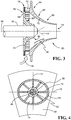
- At least one swirler 64 is positioned around a swirler axis 66 extending axially through each fuel injector 62, as seen in FIG. 3 , to allow combustion air 36 to enter the combustion chamber 53 and mix with the fuel 40.
- the swirler 64 has a swirler housing 65 which includes an inner shroud 68 positioned immediately around the fuel injector 62 and an outer shroud 70 positioned radially outward from the inner shroud 68.
- a plurality of swirler vanes 72 are positioned between the shrouds 68 and 70 such that combustion air 36 may enter into the combustion chamber 53 through a plurality of air passages 74 between the swirler vanes 72.
- each swirler 64 there may be a centerline 76 along the bulkhead 58 parallel to the shells 50 and 52 of the combustor 34 and extending through a circumferential diameter of each swirler 64.
- the swirler 64 may be oblong shaped, such that the shrouds 68 and 70 and the swirler vanes 72 have a circumferential diameter greater than a radial diameter, with respect to the central axis 26, and are symmetric about the centerline 76.
- oblong used herein is defined as a roughly circular shape having a circumferential diameter greater than a radial diameter with respect to the central axis 26, as opposed to a circle which has an equal diameter in all directions. It is therefore intended that a swirler or swirler component having a major diameter extending in a circumferential direction about centerline 76 greater than a minor diameter extending in a radial direction about radial line 77 be considered to have an oblong shape.
- the shapes in the respective quadrants formed by lines 76 and 77 need not be symmetric about lines 76 and/or 77 nor common in geometry.
- the swirler 64 may incorporate both circular and oblong shapes.
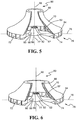
- a proximal end 78 of the swirler 64 may be oblong as described above, while a distal end 80 of the swirler 64 may be circular, as in FIG. 5 .
- the swirler vanes 72 and a proximal end 82 and 84 of the shrouds 68 and 70, respectively have an oblong shape; while a distal end 86 and 88 of the shrouds 68 and 70, respectively, have a circular shape.
- the shrouds 68 and 70 may include a transitional wall 90 and 92, respectively, which smoothly extends from the oblong proximal end 82 and 84 to the circular distal end 86 and 88, respectively.
- the distal end 80 may be oblong while the proximal end 78 may be circular.
- the swirler vanes 72 and proximal ends 82 and 84 have a circular shape, while the distal ends 86 and 88 have an oblong shape.
- the transitional walls 90 and 92 smoothly extend from the circular proximal ends 82 and 84 to the oblong distal ends 86 and 88.
- the oblong shape of the swirler vanes 72 improves the mixing of the combustion air 36 and fuel 40 by increasing the turbulence of the combustion air 36 entering into the swirler housing 65 through the air passages 74 over prior art circular swirler vanes. Additionally, the oblong shape of the swirler vanes 72 allow the combustion air 36 to be distributed in a more preferential arrangement, such as homogenously, throughout the combustion chamber 53, which will provide a more preferential mixing of the air 36 and fuel 40.
- the improvement to the air-fuel mixing is amplified by the oblong shape of the proximal end 78 of the swirler 64, which provides a larger space for the air-fuel mixing to take place and allows the air-fuel mixture to reach a more preferential distribution, such as a homogeneous distribution, than in a strictly circular swirler.
- the oblong shape of the distal end 80 of the swirler 64 allows for a more homogenous spread of the air-fuel mixture in the combustion chamber 53. This homogenous spread of the air-fuel mixture may be particularly beneficial in an annular combustor 34, which due to the geometry of the combustor 34, typically cannot achieve the same air-fuel spread with a circular swirler 34.
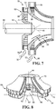
- a first swirler 94 is positioned around the fuel injector 62 as described above and a second swirler 96 is positioned radially outward from the first swirler 94.
- the outer shroud 70 of the first swirler 94 and the inner shroud 68 of the second swirler 96 may be joined to create an inner cone 98.
- one or both of the swirlers 94 and 96 may have an oblong shape.
- the inner swirler 94 and inner shroud 68 have a circular shape while the second swirler 96, inner cone 98, and outer shroud 70 have an oblong shape.
- any combination of oblong and circular shapes may be present in each swirler 94 and 96.
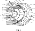
- FIG. 9 One such embodiment is presented in FIG. 9 , wherein the fuel injector 62 has a central nozzle 53 as well as a plurality of fuel injection holes 102 positioned annularly around the fuel injector 62 and through a second inner wall 104 of the swirler assembly 100.
- the second inner wall 104 is positioned between a second axial wall 106 and the inner cone 98 of the swirler assembly 100.
- the swirler assembly 100 of FIG. 9 also provides an exemplary embodiment of a multi-swirler assembly where a first swirler 94 is positioned around the central fuel nozzle 53 and a second swirler 96 is positioned radially surrounding the first swirler 94 with an inner cone 98 separating the two swirlers 94 and 96. Both the first and second swirlers 94 and 96 have an oblong shape as well as the inner shroud 68 and inner cone 98. Radially surrounding the second swirler 96 is a first inner wall 108 which is also of an oblong shape. A first axial wall 110 extends axially from an outer radial edge 112 of the first inner wall 108.
- the first axial wall 110 also defines an oblong shape around the swirler axis 66 and along the centerline 76.
- a second axial wall 106 is positioned radially outwards from and surrounding the first axial wall 110.
- the axial walls 106 and 110 are connected by the second inner wall 104.
- An oblong axial swirler 114 is disposed through the second inner wall 104.
- a plurality of oblong radial swirlers 116 are disposed through the second axial wall 106 near the second inner wall 104.
- each swirler 64 may be oblong, circular shaped, or a mixture of oblong and circular shapes.
- the defining walls of the swirler assembly 100 while shown as oblong in FIG. 9 , may be either oblong shaped or circular as desired. Any known fuel injection system may also be included in the swirler assembly 100.
- the oblong swirler disclosed herein has industrial applicability in a variety of settings such as, but not limited to mixing air and fuel in a combustion chamber of a gas turbine engine.
- the gas turbine engine may be utilized in conjunction with an aircraft for generating power and thrust or in land based systems for generating power.
- an oblong swirler may be constructed to create turbulence and alter the air distribution in a combustion chamber, and more specifically in an annular combustion chamber. This oblong shape of the swirler may increase the effectiveness of the turbulence created for mixing the air and fuel injected into the combustion chamber as well as distribute the air into the combustion chamber in a more preferential arrangement.
- the oblong swirler may also allow for the mixture to reach a preferential mix before entering into the combustion chamber.
- the asymmetry introduced by the geometry of the swirler can provide an enhanced flow field (velocity, turbulence, shear, circulation) for mixing with the fuel introduced from the nozzle.
- This can provide enhanced premixing of the fuel-air before it is introduced to the combustor which is critical to emissions and reducing fueling complexity.
- the oblong geometry can provide preferential fuel-air distributions to the downstream combustor section to assist with mixing with other air sources (cooling, dilution, trim) and fuel-air mixtures from adjacent fuel nozzle-air swirler assemblies. This can positively impact the ability to get optimal fuel-air in the vicinity of igniters and combustor exit temperatures and patterns (e.g. pattern and profile factors).
- An oblong assembly may also permit a lower-count fuel nozzle arrangement in a combustor of given mean radius. This can reduce weight and cost and it may provide better count coupling with the downstream turbine stage.
Landscapes
- Engineering & Computer Science (AREA)
- Chemical & Material Sciences (AREA)
- Combustion & Propulsion (AREA)
- Mechanical Engineering (AREA)
- General Engineering & Computer Science (AREA)
Claims (11)
- Coupelle rotative (64 ; 94), comprenant :une enveloppe externe (70) et une enveloppe interne (68), l'enveloppe interne (68) étant positionnée radialement à l'intérieur de l'enveloppe externe (70), au moins l'une des enveloppe externe et interne (70, 68) ayant un diamètre majeur qui est supérieur à un diamètre mineur de sorte que les enveloppes (70, 68) définissent une forme oblongue ; etune pluralité d'aubes (72) positionnées entre les enveloppes interne et externe (68, 70) ;caractérisée en ce que :les deux enveloppes interne et externe (68, 70) ont une forme oblongue ;dans laquelle :
la coupelle rotative est de forme oblongue au niveau d'une extrémité distale (80), de forme circulaire au niveau d'une extrémité proximale (78), et les enveloppes interne et externe (68, 70) passent d'une forme circulaire au niveau de l'extrémité proximale (78) à une forme oblongue au niveau de l'extrémité distale (80). - Coupelle rotative selon la revendication 1, dans laquelle les aubes (72) sont positionnées entre les enveloppes interne et externe (68, 70) dans une forme oblongue.
- Coupelle rotative selon une quelconque revendication précédente, comprenant en outre une seconde coupelle rotative (96) positionnée autour de la première coupelle rotative (94).
- Coupelle rotative selon la revendication 3, dans laquelle la seconde coupelle rotative (96) a une forme oblongue.
- Coupelle rotative selon une quelconque revendication précédente, dans laquelle la coupelle rotative (94) est un composant d'un ensemble coupelle rotative (100), l'ensemble coupelle rotative (100) comprenant une pluralité de coupelles rotatives (94, 96) ayant des formes oblongue, circulaire ou un mélange de formes oblongue et circulaire.
- Moteur à turbine à gaz (20), comprenant :un compresseur (25, 27) ;une chambre de combustion (34) située axialement derrière le compresseur (25, 27) et ayant au moins une coupelle rotative (69 ; 94) positionnée à travers une cloison avant (58), dans lequel chaque coupelle rotative (69 ; 94) est une coupelle rotative selon l'une quelconque des revendications 1 à 3 ; etune turbine (47, 49) située axialement derrière la chambre de combustion (34) et reliée au compresseur (25, 27) par un arbre rotatif (28, 29).
- Moteur à turbine à gaz selon la revendication 6, dans lequel la chambre de combustion (34) a une forme annulaire et un diamètre circonférentiel de la coupelle rotative (64 ; 94) par rapport à la chambre de combustion (34) est supérieur à un diamètre radial de la coupelle rotative (64 ; 94) par rapport à la chambre de combustion (34).
- Moteur à turbine à gaz selon la revendication 7, dans lequel la forme de coupelle rotative est symétrique autour d'une ligne centrale de la cloison avant (58).
- Procédé de mélange d'air et de carburant avec une coupelle rotative oblongue (64 ; 94), dans lequel la coupelle rotative (64 ; 94) comprend une enveloppe externe (70) et une enveloppe interne (68) positionnée radialement à l'intérieur de l'enveloppe externe (70), dans lequel le procédé comprend :l'injection de carburant (40) dans un boîtier (65) de la coupelle rotative (64 ; 94) par un système d'injection de carburant ; etla création d'une turbulence mélangeuse avec l'air s'écoulant à travers une pluralité de passages d'air entre une pluralité d'aubes (72) disposées dans le boîtier de la coupelle rotative (64 ; 94) et agencées dans une forme oblongue ;caractérisé en ce que les deux enveloppes interne et externe (68, 70) ont une forme oblongue ; dans lequella coupelle rotative est de forme oblongue au niveau d'une extrémité distale (80), de forme circulaire au niveau d'une extrémité proximale (78), et les enveloppes interne et externe (68, 70) passent d'une forme circulaire au niveau de l'extrémité proximale (78) à une forme oblongue au niveau de l'extrémité distale (80).
- Procédé selon la revendication 9, comprenant en outre la fourniture d'un prémélange préférentiel de l'air et du carburant avec le boîtier de la coupelle rotative (64 ; 94) ayant une extrémité proximale de forme oblongue (78).
- Procédé selon la revendication 10 ou 11, comprenant en outre la dispersion du mélange air-carburant dans une chambre de combustion dans une distribution de flux air-carburant préférentielle par le boîtier de la coupelle rotative (64 ; 94) ayant une extrémité distale de forme oblongue (80).
Applications Claiming Priority (2)
| Application Number | Priority Date | Filing Date | Title |
|---|---|---|---|
| US13/717,232 US9404656B2 (en) | 2012-12-17 | 2012-12-17 | Oblong swirler assembly for combustors |
| PCT/US2013/068744 WO2014099159A1 (fr) | 2012-12-17 | 2013-11-06 | Ensemble coupelle rotative oblongue pour chambres de combustion |
Publications (3)
| Publication Number | Publication Date |
|---|---|
| EP2932157A1 EP2932157A1 (fr) | 2015-10-21 |
| EP2932157A4 EP2932157A4 (fr) | 2016-01-06 |
| EP2932157B1 true EP2932157B1 (fr) | 2018-05-09 |
Family
ID=50929325
Family Applications (1)
| Application Number | Title | Priority Date | Filing Date |
|---|---|---|---|
| EP13865651.7A Active EP2932157B1 (fr) | 2012-12-17 | 2013-11-06 | Ensemble coupelle rotative oblongue pour chambres de combustion |
Country Status (3)
| Country | Link |
|---|---|
| US (1) | US9404656B2 (fr) |
| EP (1) | EP2932157B1 (fr) |
| WO (1) | WO2014099159A1 (fr) |
Cited By (1)
| Publication number | Priority date | Publication date | Assignee | Title |
|---|---|---|---|---|
| US12276423B2 (en) | 2021-09-23 | 2025-04-15 | General Electric Company | Floating primary vane swirler |
Families Citing this family (13)
| Publication number | Priority date | Publication date | Assignee | Title |
|---|---|---|---|---|
| US9376985B2 (en) * | 2012-12-17 | 2016-06-28 | United Technologies Corporation | Ovate swirler assembly for combustors |
| EP3098514A1 (fr) * | 2015-05-29 | 2016-11-30 | Siemens Aktiengesellschaft | Agencement de chambre de combustion |
| US20180058696A1 (en) * | 2016-08-23 | 2018-03-01 | General Electric Company | Fuel-air mixer assembly for use in a combustor of a turbine engine |
| US20200224877A1 (en) * | 2016-10-21 | 2020-07-16 | Fgc Plasma Solutions | Apparatus and method for using plasma to assist with the combustion of fuel |
| US11149952B2 (en) * | 2016-12-07 | 2021-10-19 | Raytheon Technologies Corporation | Main mixer in an axial staged combustor for a gas turbine engine |
| US20180335214A1 (en) * | 2017-05-18 | 2018-11-22 | United Technologies Corporation | Fuel air mixer assembly for a gas turbine engine combustor |
| US10591163B2 (en) * | 2017-07-21 | 2020-03-17 | United Technologies Corporation | Swirler for combustor of gas turbine engine |
| US10717245B2 (en) | 2018-04-03 | 2020-07-21 | Johns Manville | System for producing a fully impregnated thermoplastic prepreg |
| US11378275B2 (en) * | 2019-12-06 | 2022-07-05 | Raytheon Technologies Corporation | High shear swirler with recessed fuel filmer for a gas turbine engine |
| US11280495B2 (en) | 2020-03-04 | 2022-03-22 | General Electric Company | Gas turbine combustor fuel injector flow device including vanes |
| US12220879B2 (en) | 2021-02-11 | 2025-02-11 | Johns Manville | Lightweight thermoplastic composite products and methods of making same |
| US12072099B2 (en) * | 2021-12-21 | 2024-08-27 | General Electric Company | Gas turbine fuel nozzle having a lip extending from the vanes of a swirler |
| EP4202304B1 (fr) | 2021-12-21 | 2025-02-26 | General Electric Company | Moteur à turbine avec buse de carburant et tourbillonneur |
Family Cites Families (11)
| Publication number | Priority date | Publication date | Assignee | Title |
|---|---|---|---|---|
| US2545495A (en) * | 1947-08-06 | 1951-03-20 | Westinghouse Electric Corp | Annular combustion chamber air flow arrangement about the fuel nozzle end |
| GB1135670A (en) * | 1966-04-20 | 1968-12-04 | Rolls Royce | Combustion chamber for a gas turbine engine |
| US4288980A (en) | 1979-06-20 | 1981-09-15 | Brown Boveri Turbomachinery, Inc. | Combustor for use with gas turbines |
| US4763482A (en) | 1987-01-02 | 1988-08-16 | General Electric Company | Swirler arrangement for combustor of gas turbine engine |
| FR2698157B1 (fr) * | 1992-11-18 | 1994-12-16 | Snecma | Système d'injection aérodynamique de chambre de combustion. |
| US6119459A (en) * | 1998-08-18 | 2000-09-19 | Alliedsignal Inc. | Elliptical axial combustor swirler |
| US6354072B1 (en) * | 1999-12-10 | 2002-03-12 | General Electric Company | Methods and apparatus for decreasing combustor emissions |
| US6581386B2 (en) | 2001-09-29 | 2003-06-24 | General Electric Company | Threaded combustor baffle |
| US20080163627A1 (en) | 2007-01-10 | 2008-07-10 | Ahmed Mostafa Elkady | Fuel-flexible triple-counter-rotating swirler and method of use |
| GB2456147B (en) * | 2008-01-03 | 2010-07-14 | Rolls Royce Plc | Fuel Injector Assembly for Gas Turbine Engines |
| GB201222304D0 (en) | 2012-12-12 | 2013-01-23 | Rolls Royce Plc | A fuel injector and a gas turbine engine combustion chamber |
-
2012
- 2012-12-17 US US13/717,232 patent/US9404656B2/en active Active
-
2013
- 2013-11-06 WO PCT/US2013/068744 patent/WO2014099159A1/fr not_active Ceased
- 2013-11-06 EP EP13865651.7A patent/EP2932157B1/fr active Active
Non-Patent Citations (1)
| Title |
|---|
| None * |
Cited By (1)
| Publication number | Priority date | Publication date | Assignee | Title |
|---|---|---|---|---|
| US12276423B2 (en) | 2021-09-23 | 2025-04-15 | General Electric Company | Floating primary vane swirler |
Also Published As
| Publication number | Publication date |
|---|---|
| US20140165585A1 (en) | 2014-06-19 |
| EP2932157A1 (fr) | 2015-10-21 |
| WO2014099159A1 (fr) | 2014-06-26 |
| EP2932157A4 (fr) | 2016-01-06 |
| US9404656B2 (en) | 2016-08-02 |
Similar Documents
| Publication | Publication Date | Title |
|---|---|---|
| EP2932157B1 (fr) | Ensemble coupelle rotative oblongue pour chambres de combustion | |
| US9376985B2 (en) | Ovate swirler assembly for combustors | |
| US11236906B2 (en) | Combustor cooled quench zone array | |
| US10072846B2 (en) | Trapped vortex cavity staging in a combustor | |
| EP2481987B1 (fr) | Assemblage de mélangeur pour moteur de turbine à gaz | |
| EP2413036B1 (fr) | Chambres de combustion avec des inserts de trempe | |
| US20130255265A1 (en) | Combustors with quench inserts | |
| US8555645B2 (en) | Fuel nozzle centerbody and method of assembling the same | |
| KR101774630B1 (ko) | 가스 터빈 엔진에 사용되는 예비혼합된 연료와 공기를 가진 접선방향의 애뉼러형 연소실 | |
| AU2022202433B2 (en) | Furcating pilot pre-mixer for main mini-mixer array in a gas turbine engine | |
| US8584466B2 (en) | Circumferentially varied quench jet arrangement for gas turbine combustors | |
| CN115388426B (zh) | 用于燃油喷嘴的隔热罩 | |
| CN115371082B (zh) | 具有通风文丘里管的先导燃料喷嘴组件 | |
| EP3130855B1 (fr) | Paroi de chambre de combustion de turbine à gaz comprenant une agencement de perforations | |
| CN115899765A (zh) | 用于降低排放的带有旋流轮叶的环形燃烧器稀释 | |
| KR101832026B1 (ko) | 가스 터빈 엔진에 사용되는 접선방향의 무염 애뉼러형 연소실 | |
| US12286932B1 (en) | Turbine engine combustor including a heat shield | |
| EP3220048A1 (fr) | Refroidissement d'une chemise de combustion |
Legal Events
| Date | Code | Title | Description |
|---|---|---|---|
| PUAI | Public reference made under article 153(3) epc to a published international application that has entered the european phase |
Free format text: ORIGINAL CODE: 0009012 |
|
| 17P | Request for examination filed |
Effective date: 20150717 |
|
| AK | Designated contracting states |
Kind code of ref document: A1 Designated state(s): AL AT BE BG CH CY CZ DE DK EE ES FI FR GB GR HR HU IE IS IT LI LT LU LV MC MK MT NL NO PL PT RO RS SE SI SK SM TR |
|
| AX | Request for extension of the european patent |
Extension state: BA ME |
|
| A4 | Supplementary search report drawn up and despatched |
Effective date: 20151209 |
|
| RIC1 | Information provided on ipc code assigned before grant |
Ipc: F23R 3/14 20060101AFI20151203BHEP |
|
| DAX | Request for extension of the european patent (deleted) | ||
| RAP1 | Party data changed (applicant data changed or rights of an application transferred) |
Owner name: UNITED TECHNOLOGIES CORPORATION |
|
| STAA | Information on the status of an ep patent application or granted ep patent |
Free format text: STATUS: EXAMINATION IS IN PROGRESS |
|
| 17Q | First examination report despatched |
Effective date: 20170104 |
|
| GRAP | Despatch of communication of intention to grant a patent |
Free format text: ORIGINAL CODE: EPIDOSNIGR1 |
|
| STAA | Information on the status of an ep patent application or granted ep patent |
Free format text: STATUS: GRANT OF PATENT IS INTENDED |
|
| INTG | Intention to grant announced |
Effective date: 20171122 |
|
| GRAS | Grant fee paid |
Free format text: ORIGINAL CODE: EPIDOSNIGR3 |
|
| GRAA | (expected) grant |
Free format text: ORIGINAL CODE: 0009210 |
|
| STAA | Information on the status of an ep patent application or granted ep patent |
Free format text: STATUS: THE PATENT HAS BEEN GRANTED |
|
| AK | Designated contracting states |
Kind code of ref document: B1 Designated state(s): AL AT BE BG CH CY CZ DE DK EE ES FI FR GB GR HR HU IE IS IT LI LT LU LV MC MK MT NL NO PL PT RO RS SE SI SK SM TR |
|
| REG | Reference to a national code |
Ref country code: GB Ref legal event code: FG4D |
|
| REG | Reference to a national code |
Ref country code: CH Ref legal event code: EP Ref country code: AT Ref legal event code: REF Ref document number: 997930 Country of ref document: AT Kind code of ref document: T Effective date: 20180515 |
|
| REG | Reference to a national code |
Ref country code: IE Ref legal event code: FG4D |
|
| REG | Reference to a national code |
Ref country code: DE Ref legal event code: R096 Ref document number: 602013037363 Country of ref document: DE |
|
| REG | Reference to a national code |
Ref country code: NL Ref legal event code: MP Effective date: 20180509 |
|
| REG | Reference to a national code |
Ref country code: LT Ref legal event code: MG4D |
|
| REG | Reference to a national code |
Ref country code: FR Ref legal event code: PLFP Year of fee payment: 6 |
|
| PG25 | Lapsed in a contracting state [announced via postgrant information from national office to epo] |
Ref country code: SE Free format text: LAPSE BECAUSE OF FAILURE TO SUBMIT A TRANSLATION OF THE DESCRIPTION OR TO PAY THE FEE WITHIN THE PRESCRIBED TIME-LIMIT Effective date: 20180509 Ref country code: FI Free format text: LAPSE BECAUSE OF FAILURE TO SUBMIT A TRANSLATION OF THE DESCRIPTION OR TO PAY THE FEE WITHIN THE PRESCRIBED TIME-LIMIT Effective date: 20180509 Ref country code: BG Free format text: LAPSE BECAUSE OF FAILURE TO SUBMIT A TRANSLATION OF THE DESCRIPTION OR TO PAY THE FEE WITHIN THE PRESCRIBED TIME-LIMIT Effective date: 20180809 Ref country code: NO Free format text: LAPSE BECAUSE OF FAILURE TO SUBMIT A TRANSLATION OF THE DESCRIPTION OR TO PAY THE FEE WITHIN THE PRESCRIBED TIME-LIMIT Effective date: 20180809 Ref country code: LT Free format text: LAPSE BECAUSE OF FAILURE TO SUBMIT A TRANSLATION OF THE DESCRIPTION OR TO PAY THE FEE WITHIN THE PRESCRIBED TIME-LIMIT Effective date: 20180509 Ref country code: ES Free format text: LAPSE BECAUSE OF FAILURE TO SUBMIT A TRANSLATION OF THE DESCRIPTION OR TO PAY THE FEE WITHIN THE PRESCRIBED TIME-LIMIT Effective date: 20180509 |
|
| PG25 | Lapsed in a contracting state [announced via postgrant information from national office to epo] |
Ref country code: NL Free format text: LAPSE BECAUSE OF FAILURE TO SUBMIT A TRANSLATION OF THE DESCRIPTION OR TO PAY THE FEE WITHIN THE PRESCRIBED TIME-LIMIT Effective date: 20180509 Ref country code: HR Free format text: LAPSE BECAUSE OF FAILURE TO SUBMIT A TRANSLATION OF THE DESCRIPTION OR TO PAY THE FEE WITHIN THE PRESCRIBED TIME-LIMIT Effective date: 20180509 Ref country code: GR Free format text: LAPSE BECAUSE OF FAILURE TO SUBMIT A TRANSLATION OF THE DESCRIPTION OR TO PAY THE FEE WITHIN THE PRESCRIBED TIME-LIMIT Effective date: 20180810 Ref country code: LV Free format text: LAPSE BECAUSE OF FAILURE TO SUBMIT A TRANSLATION OF THE DESCRIPTION OR TO PAY THE FEE WITHIN THE PRESCRIBED TIME-LIMIT Effective date: 20180509 Ref country code: RS Free format text: LAPSE BECAUSE OF FAILURE TO SUBMIT A TRANSLATION OF THE DESCRIPTION OR TO PAY THE FEE WITHIN THE PRESCRIBED TIME-LIMIT Effective date: 20180509 |
|
| REG | Reference to a national code |
Ref country code: AT Ref legal event code: MK05 Ref document number: 997930 Country of ref document: AT Kind code of ref document: T Effective date: 20180509 |
|
| PG25 | Lapsed in a contracting state [announced via postgrant information from national office to epo] |
Ref country code: RO Free format text: LAPSE BECAUSE OF FAILURE TO SUBMIT A TRANSLATION OF THE DESCRIPTION OR TO PAY THE FEE WITHIN THE PRESCRIBED TIME-LIMIT Effective date: 20180509 Ref country code: CZ Free format text: LAPSE BECAUSE OF FAILURE TO SUBMIT A TRANSLATION OF THE DESCRIPTION OR TO PAY THE FEE WITHIN THE PRESCRIBED TIME-LIMIT Effective date: 20180509 Ref country code: EE Free format text: LAPSE BECAUSE OF FAILURE TO SUBMIT A TRANSLATION OF THE DESCRIPTION OR TO PAY THE FEE WITHIN THE PRESCRIBED TIME-LIMIT Effective date: 20180509 Ref country code: AT Free format text: LAPSE BECAUSE OF FAILURE TO SUBMIT A TRANSLATION OF THE DESCRIPTION OR TO PAY THE FEE WITHIN THE PRESCRIBED TIME-LIMIT Effective date: 20180509 Ref country code: PL Free format text: LAPSE BECAUSE OF FAILURE TO SUBMIT A TRANSLATION OF THE DESCRIPTION OR TO PAY THE FEE WITHIN THE PRESCRIBED TIME-LIMIT Effective date: 20180509 Ref country code: DK Free format text: LAPSE BECAUSE OF FAILURE TO SUBMIT A TRANSLATION OF THE DESCRIPTION OR TO PAY THE FEE WITHIN THE PRESCRIBED TIME-LIMIT Effective date: 20180509 Ref country code: SK Free format text: LAPSE BECAUSE OF FAILURE TO SUBMIT A TRANSLATION OF THE DESCRIPTION OR TO PAY THE FEE WITHIN THE PRESCRIBED TIME-LIMIT Effective date: 20180509 |
|
| REG | Reference to a national code |
Ref country code: DE Ref legal event code: R097 Ref document number: 602013037363 Country of ref document: DE |
|
| PG25 | Lapsed in a contracting state [announced via postgrant information from national office to epo] |
Ref country code: IT Free format text: LAPSE BECAUSE OF FAILURE TO SUBMIT A TRANSLATION OF THE DESCRIPTION OR TO PAY THE FEE WITHIN THE PRESCRIBED TIME-LIMIT Effective date: 20180509 Ref country code: SM Free format text: LAPSE BECAUSE OF FAILURE TO SUBMIT A TRANSLATION OF THE DESCRIPTION OR TO PAY THE FEE WITHIN THE PRESCRIBED TIME-LIMIT Effective date: 20180509 |
|
| PLBE | No opposition filed within time limit |
Free format text: ORIGINAL CODE: 0009261 |
|
| STAA | Information on the status of an ep patent application or granted ep patent |
Free format text: STATUS: NO OPPOSITION FILED WITHIN TIME LIMIT |
|
| 26N | No opposition filed |
Effective date: 20190212 |
|
| PG25 | Lapsed in a contracting state [announced via postgrant information from national office to epo] |
Ref country code: SI Free format text: LAPSE BECAUSE OF FAILURE TO SUBMIT A TRANSLATION OF THE DESCRIPTION OR TO PAY THE FEE WITHIN THE PRESCRIBED TIME-LIMIT Effective date: 20180509 |
|
| REG | Reference to a national code |
Ref country code: CH Ref legal event code: PL |
|
| PG25 | Lapsed in a contracting state [announced via postgrant information from national office to epo] |
Ref country code: MC Free format text: LAPSE BECAUSE OF FAILURE TO SUBMIT A TRANSLATION OF THE DESCRIPTION OR TO PAY THE FEE WITHIN THE PRESCRIBED TIME-LIMIT Effective date: 20180509 Ref country code: LU Free format text: LAPSE BECAUSE OF NON-PAYMENT OF DUE FEES Effective date: 20181106 |
|
| REG | Reference to a national code |
Ref country code: BE Ref legal event code: MM Effective date: 20181130 |
|
| REG | Reference to a national code |
Ref country code: IE Ref legal event code: MM4A |
|
| PG25 | Lapsed in a contracting state [announced via postgrant information from national office to epo] |
Ref country code: LI Free format text: LAPSE BECAUSE OF NON-PAYMENT OF DUE FEES Effective date: 20181130 Ref country code: CH Free format text: LAPSE BECAUSE OF NON-PAYMENT OF DUE FEES Effective date: 20181130 |
|
| PG25 | Lapsed in a contracting state [announced via postgrant information from national office to epo] |
Ref country code: IE Free format text: LAPSE BECAUSE OF NON-PAYMENT OF DUE FEES Effective date: 20181106 |
|
| PG25 | Lapsed in a contracting state [announced via postgrant information from national office to epo] |
Ref country code: BE Free format text: LAPSE BECAUSE OF NON-PAYMENT OF DUE FEES Effective date: 20181130 Ref country code: AL Free format text: LAPSE BECAUSE OF FAILURE TO SUBMIT A TRANSLATION OF THE DESCRIPTION OR TO PAY THE FEE WITHIN THE PRESCRIBED TIME-LIMIT Effective date: 20180509 |
|
| PG25 | Lapsed in a contracting state [announced via postgrant information from national office to epo] |
Ref country code: MT Free format text: LAPSE BECAUSE OF NON-PAYMENT OF DUE FEES Effective date: 20181106 |
|
| PG25 | Lapsed in a contracting state [announced via postgrant information from national office to epo] |
Ref country code: TR Free format text: LAPSE BECAUSE OF FAILURE TO SUBMIT A TRANSLATION OF THE DESCRIPTION OR TO PAY THE FEE WITHIN THE PRESCRIBED TIME-LIMIT Effective date: 20180509 |
|
| PG25 | Lapsed in a contracting state [announced via postgrant information from national office to epo] |
Ref country code: PT Free format text: LAPSE BECAUSE OF FAILURE TO SUBMIT A TRANSLATION OF THE DESCRIPTION OR TO PAY THE FEE WITHIN THE PRESCRIBED TIME-LIMIT Effective date: 20180509 |
|
| PG25 | Lapsed in a contracting state [announced via postgrant information from national office to epo] |
Ref country code: MK Free format text: LAPSE BECAUSE OF NON-PAYMENT OF DUE FEES Effective date: 20180509 Ref country code: HU Free format text: LAPSE BECAUSE OF FAILURE TO SUBMIT A TRANSLATION OF THE DESCRIPTION OR TO PAY THE FEE WITHIN THE PRESCRIBED TIME-LIMIT; INVALID AB INITIO Effective date: 20131106 Ref country code: CY Free format text: LAPSE BECAUSE OF FAILURE TO SUBMIT A TRANSLATION OF THE DESCRIPTION OR TO PAY THE FEE WITHIN THE PRESCRIBED TIME-LIMIT Effective date: 20180509 |
|
| PG25 | Lapsed in a contracting state [announced via postgrant information from national office to epo] |
Ref country code: IS Free format text: LAPSE BECAUSE OF FAILURE TO SUBMIT A TRANSLATION OF THE DESCRIPTION OR TO PAY THE FEE WITHIN THE PRESCRIBED TIME-LIMIT Effective date: 20180909 |
|
| REG | Reference to a national code |
Ref country code: DE Ref legal event code: R081 Ref document number: 602013037363 Country of ref document: DE Owner name: RAYTHEON TECHNOLOGIES CORPORATION (N.D.GES.D.S, US Free format text: FORMER OWNER: UNITED TECHNOLOGIES CORPORATION, FARMINGTON, CONN., US Ref country code: DE Ref legal event code: R081 Ref document number: 602013037363 Country of ref document: DE Owner name: RTX CORPORATION (N.D.GES.D. STAATES DELAWARE),, US Free format text: FORMER OWNER: UNITED TECHNOLOGIES CORPORATION, FARMINGTON, CONN., US |
|
| P01 | Opt-out of the competence of the unified patent court (upc) registered |
Effective date: 20230520 |
|
| REG | Reference to a national code |
Ref country code: DE Ref legal event code: R081 Ref document number: 602013037363 Country of ref document: DE Owner name: RTX CORPORATION (N.D.GES.D. STAATES DELAWARE),, US Free format text: FORMER OWNER: RAYTHEON TECHNOLOGIES CORPORATION (N.D.GES.D.STAATES DELAWARE), ARLINGTON, VA, US |
|
| PGFP | Annual fee paid to national office [announced via postgrant information from national office to epo] |
Ref country code: DE Payment date: 20251022 Year of fee payment: 13 |
|
| PGFP | Annual fee paid to national office [announced via postgrant information from national office to epo] |
Ref country code: GB Payment date: 20251023 Year of fee payment: 13 |
|
| PGFP | Annual fee paid to national office [announced via postgrant information from national office to epo] |
Ref country code: FR Payment date: 20251022 Year of fee payment: 13 |