EP2932178B1 - Kühlturm mit einem indirekten wärmetauscher - Google Patents
Kühlturm mit einem indirekten wärmetauscher Download PDFInfo
- Publication number
- EP2932178B1 EP2932178B1 EP13865074.2A EP13865074A EP2932178B1 EP 2932178 B1 EP2932178 B1 EP 2932178B1 EP 13865074 A EP13865074 A EP 13865074A EP 2932178 B1 EP2932178 B1 EP 2932178B1
- Authority
- EP
- European Patent Office
- Prior art keywords
- heat exchange
- exchange section
- plate
- indirect
- evaporative liquid
- Prior art date
- Legal status (The legal status is an assumption and is not a legal conclusion. Google has not performed a legal analysis and makes no representation as to the accuracy of the status listed.)
- Active
Links
Images





Classifications
-
- F—MECHANICAL ENGINEERING; LIGHTING; HEATING; WEAPONS; BLASTING
- F28—HEAT EXCHANGE IN GENERAL
- F28D—HEAT-EXCHANGE APPARATUS, NOT PROVIDED FOR IN ANOTHER SUBCLASS, IN WHICH THE HEAT-EXCHANGE MEDIA DO NOT COME INTO DIRECT CONTACT
- F28D15/00—Heat-exchange apparatus with the intermediate heat-transfer medium in closed tubes passing into or through the conduit walls ; Heat-exchange apparatus employing intermediate heat-transfer medium or bodies
-
- B—PERFORMING OPERATIONS; TRANSPORTING
- B01—PHYSICAL OR CHEMICAL PROCESSES OR APPARATUS IN GENERAL
- B01F—MIXING, e.g. DISSOLVING, EMULSIFYING OR DISPERSING
- B01F23/00—Mixing according to the phases to be mixed, e.g. dispersing or emulsifying
- B01F23/20—Mixing gases with liquids
- B01F23/23—Mixing gases with liquids by introducing gases into liquid media, e.g. for producing aerated liquids
- B01F23/232—Mixing gases with liquids by introducing gases into liquid media, e.g. for producing aerated liquids using flow-mixing means for introducing the gases, e.g. baffles
- B01F23/2321—Mixing gases with liquids by introducing gases into liquid media, e.g. for producing aerated liquids using flow-mixing means for introducing the gases, e.g. baffles by moving liquid and gas in counter current
-
- F—MECHANICAL ENGINEERING; LIGHTING; HEATING; WEAPONS; BLASTING
- F28—HEAT EXCHANGE IN GENERAL
- F28C—HEAT-EXCHANGE APPARATUS, NOT PROVIDED FOR IN ANOTHER SUBCLASS, IN WHICH THE HEAT-EXCHANGE MEDIA COME INTO DIRECT CONTACT WITHOUT CHEMICAL INTERACTION
- F28C1/00—Direct-contact trickle coolers, e.g. cooling towers
- F28C1/14—Direct-contact trickle coolers, e.g. cooling towers comprising also a non-direct contact heat exchange
-
- F—MECHANICAL ENGINEERING; LIGHTING; HEATING; WEAPONS; BLASTING
- F28—HEAT EXCHANGE IN GENERAL
- F28C—HEAT-EXCHANGE APPARATUS, NOT PROVIDED FOR IN ANOTHER SUBCLASS, IN WHICH THE HEAT-EXCHANGE MEDIA COME INTO DIRECT CONTACT WITHOUT CHEMICAL INTERACTION
- F28C3/00—Other direct-contact heat-exchange apparatus
- F28C3/06—Other direct-contact heat-exchange apparatus the heat-exchange media being a liquid and a gas or vapour
-
- F—MECHANICAL ENGINEERING; LIGHTING; HEATING; WEAPONS; BLASTING
- F28—HEAT EXCHANGE IN GENERAL
- F28D—HEAT-EXCHANGE APPARATUS, NOT PROVIDED FOR IN ANOTHER SUBCLASS, IN WHICH THE HEAT-EXCHANGE MEDIA DO NOT COME INTO DIRECT CONTACT
- F28D5/00—Heat-exchange apparatus having stationary conduit assemblies for one heat-exchange medium only, the media being in contact with different sides of the conduit wall, using the cooling effect of natural or forced evaporation
-
- F—MECHANICAL ENGINEERING; LIGHTING; HEATING; WEAPONS; BLASTING
- F28—HEAT EXCHANGE IN GENERAL
- F28D—HEAT-EXCHANGE APPARATUS, NOT PROVIDED FOR IN ANOTHER SUBCLASS, IN WHICH THE HEAT-EXCHANGE MEDIA DO NOT COME INTO DIRECT CONTACT
- F28D9/00—Heat-exchange apparatus having stationary plate-like or laminated conduit assemblies for both heat-exchange media, the media being in contact with different sides of a conduit wall
- F28D9/0031—Heat-exchange apparatus having stationary plate-like or laminated conduit assemblies for both heat-exchange media, the media being in contact with different sides of a conduit wall the conduits for one heat-exchange medium being formed by paired plates touching each other
- F28D9/0043—Heat-exchange apparatus having stationary plate-like or laminated conduit assemblies for both heat-exchange media, the media being in contact with different sides of a conduit wall the conduits for one heat-exchange medium being formed by paired plates touching each other the plates having openings therein for circulation of at least one heat-exchange medium from one conduit to another
-
- F—MECHANICAL ENGINEERING; LIGHTING; HEATING; WEAPONS; BLASTING
- F28—HEAT EXCHANGE IN GENERAL
- F28F—DETAILS OF HEAT-EXCHANGE AND HEAT-TRANSFER APPARATUS, OF GENERAL APPLICATION
- F28F3/00—Plate-like or laminated elements; Assemblies of plate-like or laminated elements
- F28F3/005—Arrangements for preventing direct contact between different heat-exchange media
-
- F—MECHANICAL ENGINEERING; LIGHTING; HEATING; WEAPONS; BLASTING
- F28—HEAT EXCHANGE IN GENERAL
- F28F—DETAILS OF HEAT-EXCHANGE AND HEAT-TRANSFER APPARATUS, OF GENERAL APPLICATION
- F28F3/00—Plate-like or laminated elements; Assemblies of plate-like or laminated elements
- F28F3/02—Elements or assemblies thereof with means for increasing heat-transfer area, e.g. with fins, with recesses, with corrugations
- F28F3/04—Elements or assemblies thereof with means for increasing heat-transfer area, e.g. with fins, with recesses, with corrugations the means being integral with the element
- F28F3/042—Elements or assemblies thereof with means for increasing heat-transfer area, e.g. with fins, with recesses, with corrugations the means being integral with the element in the form of local deformations of the element
- F28F3/046—Elements or assemblies thereof with means for increasing heat-transfer area, e.g. with fins, with recesses, with corrugations the means being integral with the element in the form of local deformations of the element the deformations being linear, e.g. corrugations
-
- Y—GENERAL TAGGING OF NEW TECHNOLOGICAL DEVELOPMENTS; GENERAL TAGGING OF CROSS-SECTIONAL TECHNOLOGIES SPANNING OVER SEVERAL SECTIONS OF THE IPC; TECHNICAL SUBJECTS COVERED BY FORMER USPC CROSS-REFERENCE ART COLLECTIONS [XRACs] AND DIGESTS
- Y02—TECHNOLOGIES OR APPLICATIONS FOR MITIGATION OR ADAPTATION AGAINST CLIMATE CHANGE
- Y02B—CLIMATE CHANGE MITIGATION TECHNOLOGIES RELATED TO BUILDINGS, e.g. HOUSING, HOUSE APPLIANCES OR RELATED END-USER APPLICATIONS
- Y02B30/00—Energy efficient heating, ventilation or air conditioning [HVAC]
- Y02B30/70—Efficient control or regulation technologies, e.g. for control of refrigerant flow, motor or heating
Definitions
- the present invention relates generally to an improved heat exchange apparatus such as a closed circuit fluid cooler, fluid heater, condenser, evaporator, thermal storage system, air cooler or air heater. More specifically, the present invention relates to a combination or combinations of separate indirect and direct evaporative heat exchange sections or components arranged to achieve improved capacity and
- CN 201463419 discloses a method of exchanging heat comprising the steps of providing an indirect heat exchange section comprised of a plate heat exchanger using a series of adjacent plate cassettes and a direct evaporative heat exchange section.
- the invention includes the use of a plate type heat exchanger as an indirect heat exchange section.
- a plate type heat exchanger When compared with coil circuit indirect heat exchangers which are comprised of individual circuits of tubing, the performance of an indirect heat exchange section comprised of a plate type heat exchanger is improved.
- Such indirect heat exchange section is combined with a direct heat exchange section, which usually is comprised of a fill section over which an evaporative liquid such as water is transferred, usually in a downwardly streaming operation.
- Such combined indirect heat exchange section and direct heat exchange section together provide improved performance as an overall heat exchange apparatus such as a closed circuit fluid cooler, fluid heater, condenser, evaporator, air cooler or air heater.
- the improved performance of the indirect heat exchange section comprising a plate heat exchanger is the capability of the indirect heat exchange section as a plate type heat exchanger to provide both sensible and latent heat exchange with the evaporative liquid which is streamed or otherwise transported over and through the indirect heat exchange section.
- Another important improvement is that plate heat exchangers will have more surface area in the same physical space as other evaporative indirect heat exchangers.
- Such arrangements could include an arrangement wherein the indirect heat exchange section is physically located above the direct heat exchange section or is physically located below the direct heat exchange section.
- an evaporative liquid is streamed or otherwise sprayed downwardly onto the indirect heat exchange section with such evaporative liquid, which is usually water, then exiting the indirect section to be transported over the direct heat exchange section which is usually comprised of a fill arrangement.
- the indirect heat exchange section is physically located below the direct heat exchange section.
- two or more indirect sections are placed in a single closed circuit fluid cooler or heat exchanger each above or below a direct heat exchange section is also part of the present invention.
- the heat exchanger apparatus or fluid cooler of the present invention could be operated wherein both air and an evaporative liquid such as water are drawn or supplied across both the indirect and direct heat exchange sections. It may be desirable to operate the heat exchanger without a supply of the evaporative liquid, wherein air only would be drawn across the indirect heat exchange section.
- an indirect heat exchange section In the operation of an indirect heat exchange section, a fluid stream passing through the internal openings in the plate type heat exchanger is cooled, heated, condensed, or evaporated in either or both a sensible heat exchange operation and a latent heat exchange operation by passing an evaporative liquid such as water together with air in passages between individual plate pairs or cassettes in the indirect heat exchanger.
- an evaporative liquid such as water
- the evaporative liquid which again is usually water, which passes across or downwardly through the indirect heat exchange section then passes, usually downwardly, across or through the direct heat exchange section which is typically a fill assembly.
- Heat in the evaporative liquid is passed to air which is drawn generally downwardly, upwardly or across the direct heat exchange section and outwardly from the closed circuit fluid cooler or heat exchanger assembly by an air moving system such as a fan.
- the evaporative liquid draining from the indirect or direct heat exchange section is typically collected in a sump and then pumped upwardly for redistribution across the indirect or direct evaporative heat exchange section.
- the indirect and direct heat exchange sections can be reversed wherein, in the reversed situation where a direct heat exchange section would be located above an indirect heat exchange section, the evaporative fluid exiting the indirect section would be collected in a sump and pumped upwardly for distribution across the direct heat exchange section.
- an object of the present invention to provide an improved heat exchange apparatus, which could be a closed circuit fluid cooler, fluid heater, condenser, evaporator, air cooler or air heater, which includes an indirect heat exchange section that comprises a plate type heat exchanger with more surface area per volume than other evaporative indirect heat exchangers and a direct heat exchange section.
- the present invention provides a method of exchanging heat as claimed in claim 1.
- Various optional and preferred features are recited in the dependent claims.
- the method relates to the operation of an improved heat exchange apparatus which is comprised of a combination of an indirect heat exchange section and a direct heat exchange section.
- the indirect heat exchange section provides improved performance by utilizing a plate type heat exchanger as the indirect heat exchange section.
- the plate type heat exchanger contains more surface area per unit volume that other indirect evaporative heat exchangers.
- the plate type heat exchanger is comprised of one or more combined plate heat exchange groupings or cassettes each comprised of a pair of plates. Each cassette forms an internal passage between plates.
- Such plates are designed to allow a fluid stream to be passed there through within the cassette, exposing the fluid stream to a large surface area of one side of each plate in the cassette of the heat exchanger. Outside each plate a space is provided wherein air or an evaporative liquid such as water, or a combination of air and an evaporative liquid, can be passed to provide both sensible and latent heat exchange from the outside surfaces of the plates of the plate heat exchanger.
- air or an evaporative liquid such as water, or a combination of air and an evaporative liquid
- Such utilization of a plate heat exchanger in the closed circuit fluid cooler, fluid heater, condenser, evaporator, air cooler or air heater of the present invention provides improved performance and also allows for combined operation or alternative operation wherein only air or only an evaporative liquid or a combination of the two can be passed through or across the outside of the plates in the plate heat exchanger.
- a direct heat exchange section is located generally beneath the indirect heat exchange section whereby the evaporative liquid falling from the indirect heat exchange section is allowed to pass across or through fill and accordingly allow heat to be drawn from such evaporative liquid by a passage of air across or through the direct heat exchange section by air moving apparatus such as a fan.
- air moving apparatus such as a fan.
- evaporative liquid is collected in a sump in the bottom of closed circuit fluid cooler, fluid heater, condenser, evaporator, air cooler or air heater and pumped back for distribution, usually downwardly, across or through the indirect heat exchange section.
- a heat exchanger in accordance with a first embodiment of the present invention is shown generally at 10, Such heat exchangers generally are present in a closed circuit cooling tower with a direct heat exchange section 4 and an indirect heat exchange section 5 located above direct heat exchange section 4.
- Direct heat exchange section 4 is typically comprised of fill usually comprised of sheets of polyvinyl chloride.
- Direct heat exchange section 4 receives air through air inlet 8 on the outside of heat exchanger 10, with air being drawn generally across and somewhat upwardly through direct heat exchange section 4 by fan 6.
- Indirect heat exchange section 5 is usually comprised of plate type heat exchanger 5A having a fluid outlet 2 and a fluid inlet 1. It should be understood that the operation of fluid outlet 2 and fluid inlet 1 can be reversed if it is desired.
- the preferred air direction through the indirect heat exchange section 5 is to enter from the top of the water distribution assembly 3. Air is then drawn generally downwardly from the top through the indirect heat exchanger section 5 and exits from the bottom of section 5 by fan 6. In addition, air can also be optionally drawn through air inlet 7 and generally downwardly across and upwardly through indirect heat exchange section 5 by fan 6 with the top of the water distribution assembly 7' open or closed.
- An evaporative liquid usually water, flows downwardly from water distribution assembly 3 such that the evaporative liquid falls downwardly and through indirect heat exchange section 5.
- the evaporative liquid that passes through indirect heat exchange section 5 passes downwardly and through direct heat exchange section 4.
- Water distribution assembly 3 can be comprised of a variety of pipes with openings, or any other water distribution arrangement such as using spray nozzles, troughs, or other water distribution assemblies.
- Indirect heat exchange section 5 is usually comprised of a plate type heat exchanger 5A. A fluid to be cooled, condensed, heated, or evaporated, passes within the joined plates or cassettes of plate heat exchanger 5A.
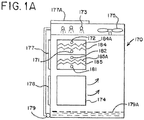
- a heat exchanger in accordance with another embodiment of the present invention is shown generally at 170.
- Such heat exchangers generally are present in a closed circuit cooling tower with a direct heat exchange section 174 and two indirect heat exchange sections 184 and 185 located above direct heat exchange section 174.
- Direct heat exchange section 174 is typically comprised of fill usually comprised of sheets of polyvinyl chloride.
- Direct heat exchange section 174 receives air through air inlet 178 on the outside of heat exchanger 170, with air being drawn generally across and somewhat upwardly through direct heat exchange section 174 by fan 175.
- the first indirect heat exchange section 184 is usually comprised of plate type heat exchanger 184A having a fluid outlet 172 and a fluid inlet 171.
- the second indirect heat exchange section 185 is usually comprised of plate type heat exchanger 185A having a fluid outlet 182 and a fluid inlet 181. It should be understood that the operation of fluid outlets 172 and 182 and fluid inlets 171 and 181 can be reversed if it is desired.
- the preferred air direction through the indirect heat exchange sections 184 and 185 is to enter from the top of the water distribution assembly 173. Air is then drawn generally downwardly from the top through the indirect heat exchanger sections 184 and 185 and exits from the bottom of section 184 and 185 by fan 175. In addition, air can also be optionally drawn through air inlet 177 and generally downwardly across and upwardly through indirect heat exchange section 184 and 185 by fan 175 with the top of the water distribution assembly 177A open or closed.
- An evaporative liquid flows downwardly from water distribution assembly 173 such that the evaporative liquid falls downwardly and through indirect heat exchange sections 184 and 185.
- the evaporative liquid that passes through indirect heat exchange sections 184 and 185 passes downwardly and through direct heat exchange section 174.
- the evaporative liquid that passes downwardly and out from direct heat exchange section 174 is collected in sump 179A and is pumped upwardly by pump 179 for redistribution through water distribution assembly 173.
- Water distribution assembly 173 can be comprised of a variety of pipes with openings, or any other water distribution arrangement such as using spray nozzles, troughs, or other water distribution assemblies.
- Indirect heat exchange sections 184 and 185 are usually comprised of a plate type heat exchanger 184 and 185A, respectively. Two fluids to be cooled, condensed, heated, or evaporated, pass independently within the joined plates or cassettes of plate heat exchanger 184 and 185A as separate fluid streams.
- FIG. 2 is a side view of the second embodiment of heat exchanger 20 in accordance with a second embodiment of the present invention.
- Heat exchanger 20 is usually a closed circuit cooling tower including an indirect heat exchange section 15 located above a direct heat exchange section 14, with the understanding that two such indirect and direct sections are provided as part of heat exchanger 20.
- Direct heat exchange section 14 is again comprised of fill sheets of a suitable material such as polyvinyl chloride. Air to be passed across and generally crossways through direct heat exchange section 14 enters through air inlet 18 and is drawn by fan 16.
- Indirect heat exchange section 15 is usually comprised of a plate heat exchanger 15A. The preferred air direction through the indirect heat exchange section 15 is to enter from the top of the evaporative liquid distribution arrangement 13A.
- Air is then drawn generally downwardly from the top through the indirect heat exchanger section 15 and exits from the bottom of section 15 by fan 16.
- air can also be optionally drawn downwardly, across and generally upwardly through indirect heat exchange section 15 entering through air inlet 17 by fan 16 with the top of the liquid distribution arrangement 17' open or closed.
- Evaporative liquid is provided to flow downwardly from an evaporative liquid distribution arrangement 13A. Such evaporative liquid passes generally downwardly across indirect heat exchange section 15.
- the evaporative liquid that exits indirect heat exchange section 15 passes downwardly through direct heat exchange section 14 and is collected in sump 19A.
- Such collected evaporative liquid is pumped by pump 19 upwardly for distribution to water evaporative liquid distribution assembly 13A.
- Plate heat exchanger 15A includes fluid outlet 12 and fluid inlet 13, which can be reversed if it is desired.
- a fluid to be cooled, condensed, heated or evaporated passes within the joined plates or cassettes of plate heat exchanger 15A.
- both such heat exchangers may be operated with both evaporative liquid exiting the evaporative liquid distribution system and the fan drawing air across and through the direct and indirect heat exchange sections.
- the unit may be operated such that the evaporative liquid would not be supplied through the evaporative liquid distribution assembly, and the heat exchanger would operate only with the fluid passing within the indirect heat exchange section joined plate pairs being cooled by air passing downwardly or across and upwardly drawn by the fan in the heat exchanger or cooling tower.
- Heat exchanger 30 is comprised of a direct heat exchange section 34 which is located generally above an indirect heat exchange section 35.
- Direct heat exchange section 34 is usually comprised of a fill sheet assembly wherein the fill sheets are typically comprised of polyvinyl chloride.
- An evaporative liquid usually water is distributed downwardly from evaporative liquid distribution assembly 33; such evaporative liquid passes downwardly and through direct heat exchange section 34.
- the top 33A of the evaporative liquid distribution assembly 33 is usually closed.
- Indirect heat exchange section 35 is usually comprised of a plate heat exchanger 35A which is comprised of a series of joined plate cassettes with separated spaces between each cassette. Fluid to be cooled, heated, condensed or evaporated enters through fluid inlet 31 and exits through fluid outlet 32, although such can be reversed if it is desired. Air passes through the indirect heat exchange section 35 and between plate pairs or cassettes of the plate heat exchanger entering through air inlet 37 and drawn by fan 36.
- air inlet 38 can be partially open to change the air flow ratio between the indirect and the direct heat exchange sections or can be fully closed which allows the full amount of air entering the direct heat exchange section
- Evaporative liquid falling from direct heat exchange section 34 passes between the plate pairs or cassettes of plate heat exchanger 35 and provides both sensible and latent heat transfer of the fluid passing within the joined plates in plate heat exchanger 35A.
- Such evaporative liquid is collected in sump 39A and is pumped upwardly through using pump 39 for redistribution through evaporative distribution assembly 33.
- FIG. 4 a fourth embodiment of a heat exchanger assembly is shown generally at 40 in accordance with the present invention.
- two direct heat exchanger sections 44 are located above two indirect heat exchanger sections 45.
- Evaporative liquid exits evaporative liquid distribution assembly 43 and is distributed downwardly through direct heat exchange section 44 which is usually comprised of a series of fill sheets made of polyvinyl chloride.
- the top 43A of the evaporative liquid distribution assembly 43 is usually closed. Air passed across and generally upwardly through direct heat exchange section 44 entering through air inlet 48 and with air drawn by fan 46.
- air inlet 48 can be partially open to change the air flow ratio between the indirect and the direct heat exchange sections or can be fully closed which allows the full amount of air entering the direct heat exchange section.
- Indirect heat exchange section 45 is usually comprised of a series of plate heat exchangers 45A.
- Such plate heat exchangers allow a fluid to be passed through the joined plates or cassettes thereby exposing such fluid to a large surface area of the plates themselves.
- Such plates are usually arranged such that a space between each joined plate pair or cassette is provided for the evaporative liquid to be passed there through, currently with air, to allow both sensible and latent heat transfer of the evaporative liquid passing between the plates. Further air enters and passes across and upwardly through the plate heat exchanger 45. Air is drawn through air inlet 47 and outwardly by fan 46. Evaporative liquid passing downwardly through indirect heat exchange section 45 is collected in sump 49A and is pumped upwardly by pump 49 to be distributed again through evaporative liquid distribution assembly 43.
- both such heat exchangers may be operated with both evaporative liquid exiting the evaporative liquid distribution system and the fan drawing air across and through the direct and heat exchange sections. It is possible to operate without the fan drawing air across the indirect and direct sections, such that only the evaporative liquid would exit and pass downwardly and through the indirect and direct heat exchange sections.
- the evaporative liquid would not be supplied through the evaporative liquid distribution assembly, and the heat exchanger would operate only with the fluid passing through the indirect heat exchange section joined plate pairs or cassettes being cooled, heated, condensed, or evaporated by air passing across and upwardly there through drawn by the fan in the heat exchanger or cooling tower.
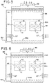
- a fifth embodiment of the present invention is shown as a heat exchanger in a closed circuit cooling tower assembly 50.
- Such heat exchanger is shown to be comprised of a direct heat exchange section 54 located generally above two indirect heat exchange sections 55.
- Direct heat exchange section 54 is usually comprised of a series of fill sheets with each fill sheet being comprised of polyvinyl chloride.
- Each indirect heat exchange section is comprised of a plate heat exchanger arrangement having a fluid outlet 52 and a fluid inlet 51, which can be reversed if it is desired. Air is drawn inwardly through air inlets 57 by fan 56. Evaporative liquid passes from evaporative distribution assembly 53 downwardly and through direct heat exchange section 54.
- Evaporative liquid passing through direct heat exchange section 54 passes downwardly through both indirect heat exchange sections 55, Evaporative liquid passing from indirect heat exchange sections 55 is collected in sump 59A, and is pumped upwardly by pump 59 for distribution through evaporative liquid distribution assembly 53.
- Indirect heat exchange section 55 is comprised of a collection of joined plate pairs or cassettes 55A. Each plate pair is separated such that evaporative liquid passing downwardly through indirect heat exchange section 55 can draw heat from the fluid within plate pairs 55A sensibly by contact with the outside of the plates. All of the heat is eventually released to the air from the evaporative fluid in both latent and sensible fashions in the evaporative passage.
- heat exchanger 50 may be operated with both evaporative liquid exiting the evaporative liquid distribution system and the fan drawing air across and through the direct and indirect heat exchange sections. It is possible to operate without the fan drawing air across the indirect and direct sections, such that only the evaporative liquid would exit and pass downwardly and through the indirect and direct heat exchange sections. Finally, it is possible again that the evaporative liquid would not be supplied through the evaporative liquid distribution assembly, and the heat exchanger would operate only with the fluid passing through the indirect heat exchange section plates being cooled, heated, condensed, or evaporated by air passing across and upwardly there through drawn by the fan in the heat exchanger or cooling tower.
- heat exchanger 60 which is usually a closed circuit cooling tower.
- Heat exchanger or cooling tower 60 is seen to be comprised of indirect heat exchange sections 65.
- Each indirect heat exchange section 65 is seen to be usually comprised of plate heat exchangers 65A, which are present as assemblies.
- Indirect heat exchange section 65 has a fluid outlet 61 and a fluid inlet 62, which can be reversed if it is desired.
- An evaporative liquid, usually water, is discharged from evaporative liquid distribution assembly 63 generally downwardly such that evaporative liquid passes downwardly and through indirect heat exchange section 65.
- Air is seen to be drawn inwardly through air inlets 67 generally upwardly through indirect heat exchange section 65 by fan 66. Further, evaporative liquid that passes through indirect heat exchange section 65 is collected in sump 69A and is pumped upwardly by pump 69 for redistribution through evaporative liquid distribution assembly 63. Evaporative liquid 63 that passes through plate heat exchanger 65 absorbs heat by contacting the large plate surface of plate heat exchanger 65A to absorb heat from the fluid within plate pairs 65A in a sensible fashion. All of the heat is eventually released to the air from the evaporative fluid in both latent and sensible fashions in the evaporative passage.
- heat exchanger 60 may be operated with both evaporative liquid exiting the evaporative liquid distribution system and the fan drawing air up and through the indirect heat exchange sections. If a lesser degree of heat exchange is required, it is possible to operate without the fan drawing air up and through the indirect section, such that only the evaporative liquid would exit and pass downwardly and through the indirect section. Further, if the evaporative liquid would not be supplied through the evaporative liquid distribution assembly, and the heat exchanger would operate only with the fluid passing through the indirect heat exchange section plates being cooled, heated, condensed, or evaporated by air passing up and upwardly there through drawn by the fan in the heat exchanger or cooling tower. Further, the heat exchanger may be operated with the fan drawing air up and through one of the two indirect sections, with or without the evaporative liquid being supplied.
- Heat exchanger 70 is seen to be comprised of a direct heat exchange section 74 for above two indirect heat exchange sections 75.
- Direct heat exchange section 74 is usually comprised of a series of fill sheets each comprised of polyvinyl chloride.
- Each indirect heat exchange section 75 is seen to be comprised of a series of joined plates or cassettes 75A with fluid outlet 72 and fluid inlet 71. These fluid inlet and outlet can be reversed if it is desired.
- Evaporative liquid is discharged from evaporative distribution assembly 73 downwardly onto and through direct heat exchange section 74.
- Evaporative liquid that passes through direct heat exchange section 74 passes downwardly and through indirect heat exchange sections 75.
- Evaporative liquid that passes through and out of indirect heat exchange sections 75 is collected in sump 79A and pumped upwardly by pump 79 for distribution through evaporative liquid distribution assembly 73.
- Evaporative liquid that passes through indirect heat exchange section 75 passes between the joined plates or cassettes of plate heat exchangers 75A thereby providing cooling, heating, evaporating, or condensing to the fluid passing through the joined plate pairs of plate heat exchangers 75A. Further, the evaporative liquid passes downwardly through indirect heat exchange section 75 passes between the joined plates of plate heat exchanger 75A along with air to thereby allow both sensible and latent heat exchanges of the fluid passing through the joined plate pairs of heat exchanger 75A.
- heat exchanger 70 may be operated with both evaporative liquid exiting the evaporative liquid distribution system and the fan drawing air up and through the direct and indirect heat exchange sections. It is possible to operate without the fan drawing air up and through the indirect and direct sections, such that only the evaporative liquid would exit and pass downwardly and through the indirect and direct heat exchange sections. Finally, it is possible again that the evaporative liquid would not be supplied through the evaporative liquid distribution assembly, and the heat exchanger would operate only with the fluid passing through the indirect heat exchange section plates being cooled, heated, condensed, or evaporated by air passing upwardly there through drawn by the fan in the heat exchanger or cooling tower.
- Heat exchanger 80 is seen to be comprised of a pair of indirect heat exchange sections 85.
- Each indirect heat exchange section 85 is comprised of a series of joined plates or cassettes 85 A.
- Indirect heat exchange section 85 also includes a fluid outlet 8 land a fluid inlet 82, which can be reversed as it is desired.
- Evaporative liquid is provided by evaporative liquid distribution assembly 83 to pass downwardly and through each indirect heat exchange section 85.
- Such evaporative liquid that passes through indirect heat exchange sections 85 is collected in sump 89A and is pumped upwardly by pump 89 back to evaporative liquid distribution assembly 83.
- Air that is drawn in air inlet 87 by centrifugal fan 86 passes generally upwardly or in a counter flow direction through indirect heat exchange sections 85.
- Evaporative liquid that passes through heat exchange section 85 passes between the joined plate pairs or cassettes of plate heat exchanger 85A such that the fluid passing through the joined plates of exchanger 85A is cooled, heated, condensed, or evaporated both sensibly and in a latent manner by such evaporative liquid passing downwardly over the outer surface area of the joined plates of plate heat exchanger 85A along with air.
- heat exchanger 80 may be operated with both evaporative liquid exiting the evaporative liquid distribution system and the fan drawing air up and through the indirect heat exchange section. It is possible to operate without the fan pushing air up and through the indirect section, such that only the evaporative liquid would exit and pass downwardly and through the indirect heat exchange section. Finally, it is possible again that the evaporative liquid would not be supplied through the evaporative liquid distribution assembly, and the heat exchanger would operate only with the fluid passing through the indirect heat exchange section plates being cooled, heated, condensed, or evaporated by air passing upwardly there through pushed by the fan in the heat exchanger or closed circuit cooling tower.
- Heat exchanger 90 is seen to be comprised of an indirect sections 95.
- Indirect heat exchange section 95 is seen to be comprised of a series of joined plates or cassettes 95A with fluid outlet 92 and fluid inlet 91. It should be understood that fluid outlet and fluid inlet 92 and 91 can be reversed if it is desired.
- centrifugal fan 96 is seen to be located outside the structure of heat exchanger 90 to thereby draw air inwardly through the fan structure to be passed generally upwardly through and across indirect heat exchange section 95.
- Evaporative liquid is distributed downwardly from evaporative liquid distribution assembly 93 to pass downwardly through indirect heat exchange section 95.
- Such evaporative liquid that passes out from indirect heat exchange assembly 95 is collected in sump 99A and is pumped upwardly by pump 99 for redistribution through evaporative liquid distribution assembly 93.
- Evaporative liquid that passes through heat exchange section 95 passes between the joined plate pairs or cassettes of plate heat exchanger 95A such that the fluid passing through inside of the joined plates of exchanger 95A is cooled, heated, condensed, or evaporated both sensibly and in a latent manner by such evaporative liquid passing downwardly over the outer surface area of the joined plates of plate heat exchanger 95A along with air.
- heat exchanger 90 may be operated with both evaporative liquid exiting the evaporative liquid distribution system and the fan pushing air up and through the indirect heat exchange section, it is possible to operate without the fan pushing air up and through the indirect section, such that only the evaporative liquid would exit and pass downwardly and through the indirect heat exchange section. Finally, it is possible again that the evaporative liquid would not be supplied through the evaporative liquid distribution assembly, and the heat exchanger would operate only with the fluid passing through the indirect heat exchange section plates being cooled, heated, condensed, or evaporated by air passing upwardly there through pushed by the fan in the heat exchanger or cooling tower.
- Heat exchanger 100 is seen to be comprised of an indirect heat exchange section 105 located generally below a direct heat exchange section 104.
- Direct heat exchange section 104 is usually comprised of a series of fill sheets each comprised of a polyvinyl chloride.
- Indirect heat exchange section 105 is usually comprised of a series of plate heat exchanger pairs or cassettes 105A, having a fluid outlet 101 and a fluid inlet 102. If it desired, such fluid inlet and outlet can be reversed.
- Air is seen to be drawn inwardly by fan 106 which is located outside the physical structure or attached to the outside of the physical structure of heat exchanger 100.
- Evaporative liquid is distributed downwardly from evaporative liquid distribution assembly 103. Such evaporative liquid passes downwardly through direct heat exchange section 104.
- the evaporative liquid that exits direct heat exchange section 104 passes downwardly through indirect heat exchange section 105 and is collected in a sump 109A. Such collected evaporative liquid is pumped from sump 109A by pump 109 back to water distribution assembly 103.
- Plate heat exchanger pairs or cassettes 105A are typically spaced from each other such that the fluid passing inside the plates of plate heat exchanger 105 is cooled, heated, condensed, and evaporated both sensibly and in a latent manner by the evaporative liquid passing on the outside of the plate pairs of plate heat exchanger 105 and also by the air being drawn by a counter-current manner across and generally upwardly through indirect heat exchange section 105.
- heat exchanger 100 may be operated with both evaporative liquid exiting the evaporative liquid distribution system and the fan forcing air up and through the direct and indirect heat exchange sections. It is possible to operate without the fan forcing air up and through the indirect and direct sections, such that only the evaporative liquid would exit and pass downwardly and through the indirect and direct heat exchange sections. Finally, it is possible again that the evaporative liquid would not be supplied through the evaporative liquid distribution assembly, and the heat exchanger would operate only with the fluid passing through the indirect heat exchange section plates being cooled, heated, condensed, or evaporated by air passing across and upwardly there through forced by the fan in the heat exchanger or cooling tower.
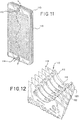
- FIGS. 11 and 12 a view of a plate heat exchanger in accordance with the present invention is shown generally at 110.
- Each plate heat exchanger is shown to be comprised of a series of joined pairs or cassettes of plates 116 spaced from each other.
- a fluid outlet header is shown at 112 and a fluid inlet header is shown at 114.
- fluid outlet header 112 is seen to include openings 118 such that fluid to be cooled, heated, evaporated or condensed may exit from within each plate pair 116.
- Each plate cassette 116 is seen to include an internal fluid passageway 122 that allows fluid to be cooled, heated, condensed, or evaporated to enter through fluid inlet header 114, pass through the interior of joined plate pairs or cassettes 116 and exit through openings 118 in each plate pair to enter outlet header 112.
- Such plate heat exchanger assembly 110 is seen to include usually a Chevron, embossing, cross hatch, dimpled, micro structurally extended, or any other surface enhancement pattern on both sides of each cassette assembly 116 to provide increased surface area and turbulent flow to allow improved performance and heat exchange between the fluid within the each cassette 116 and the air and evaporative liquid passing on the outside surface of each cassette 116.
- the geometries of the surface enhancement pattern on the plate are strategically selected such that the passageway formed in the space between each cassette assembly 116 allows good heat and mass transfer between the air and the evaporative liquid which pass concurrently between each cassette 116.
- This external passageway is usually, but not limited to, a general criss-cross pattern formed as the chevron patterns from adjacent cassettes approach close to, or even contacting, each other.
- the surface pattern could be different on each side of the plate.
- the plate surface could be chemically treated (i.e., nano spray coated) to achieve an optimized surface tension value and thus enhance the air and evaporative liquid interaction.
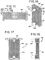
- Each plate heat exchanger in accordance with the present invention is shown generally at 130.
- Each plate heat exchanger is seen to be comprised of a series of adjacent plate pairs or cassettes 136.
- Each plate cassette 136 has an internal spacing within to allow a fluid to enter through fluid inlet header 134 pass within each plate cassette 136 and exit through fluid outlet header 132.
- Each inlet header includes a spacer ring 134A to allow header 134 to be affixed to the series of plate cassettes 1 36, and an outlet header spacer ring 1 32A to allow fluid outlet header 132 to be attached to the series of plate cassettes 136.
- spacing 138 is seen in an exploded arrangement to exist between each plate cassette 136 to provide an adequate passageway for evaporative liquid to pass in a cross-current, parallel-current, counter-current or some combination thereof arrangement with assembled plates 136.
- Such spacing also allows for air to pass between such plates such air usually being drawn in a cross-current, counter-current, parallel-current fashion or some combination thereof arrangement by fans within the heat exchanger.
- Such spacing between plate cassettes allows for increased performance of the indirect heat exchange section comprised of plate heat exchanger 130 by allowing both sensible and latent heat exchange to occur between the fluid within each plate pair or cassette 136 and the evaporative liquid and air passing in the passageway between such plate pair or cassettes 136.
- the internal passage within each plate cassette is labeled 139.
- Plate heat exchanger assembly 140 is seen to be comprised of a series of plate cassettes 146 each of which includes an internal passageway to allow fluid to pass therein. Each plate cassette is seen to ideally be comprised of a chevron or other surface arrangement to provide increased surface area of each plate pair. Plate heat exchanger assembly 140 is seen to also comprise a fluid outlet header 142 connected to the series of plate cassettes by outlet header spacer ring 142A, and a fluid inlet header 144 connected to the series of plate cassettes 146 by inlet header spacer ring 144A.
- Passageway 148 is seen to be created by the extended surface on the outside of each neighboring plate cassette 146 such that an evaporative liquid can be allowed to pass between each plate cassette 146 to provide sensible cooling for the liquid passing within each plate cassette 146. Further, passageway 148 provides space between plate cassettes 146 such that air can be drawn in a counter-current, parallel-current, cross-current fashion, or some combination thereof arrangement between plate cassettes 146 to also provide both sensible and latent heat exchange with the evaporative liquid and hence provide indirect cooling, heating, condensing, or evaporating for the fluid within plates 146.
- the spacers,149 are optional which provide extra structure support to the plate heat exchanger assembly 140 to prevent the extended surface from crushing when the plate heat exchanger assembly 140 is tightened by bolts. Also, the spacers 149 may be used to increase the width of the passageway 148 beyond its natural value which is two times of the height of the extended surface.
- Each plate heat exchanger assembly 150 is seen to be comprised of a series of plate pairs or cassettes 156 with a fluid outlet header 152 and a fluid inlet header 154.
- Each fluid inlet header 154 is connected by a fluid inlet header space ring 154A and fluid outlet header 152 is seen to be connected by a fluid outlet header space ring 152A.
- the series of plate pairs or cassettes 156 are seen to be spaced from each other by the extended surface pattern on the outside of each plate cassette 156.
- the enhanced surface pattern is on both sides. It is composed of extended surfaces (peaks, 158A) and downwardly extruded surfaces (valleys, 158B).
- the peaks 158A on one side of the plate is the valleys 158B on the other side (and vice versa).
- the valleys 158B touch each other to form the internal passageways 159 within the plate pair or cassette 156.
- the peaks 15BA on the outside surface of each plate pair 156 touch the peaks of the neighboring plate pair 156 to form the external passageway 158 (e.g., typically a criss-cross pattern) such that air and evaporative liquid can pass outside and between plate cassettes 156 to provide both good sensible and latent heat exchanges.
- Each plate cassette 156 is seen to usually have a Chevron or any other surface enhancement pattern on both sides of each cassette assembly 156 to provide increased surface area and turbulent flow to allow improved performance and heat exchange between the fluid within the each cassette 156 and the evaporative liquid passing between each cassette 156.
- the geometries of the surface enhancement pattern on the plate are strategically selected such that the external passageways 158 formed in the space between each cassette assembly 156 allows good heat and mass transfer between the air and the evaporative liquid which pass concurrently outside and between each cassette 156.
- This external passageway is usually, but not limited to, a general criss-cross pattern.
- the plates can be comprised of various steels such as stainless steel or other corrosion resistant steels and alloys. It is also possible that such plates can be comprised of other materials that would lead to good heat exchange between the fluid within the plate and the evaporative liquid or air passing outwardly therefrom. Such materials could be aluminum or copper; various alloys, or plastics that provide corrosion resistance and good heat exchange.
Landscapes
- Engineering & Computer Science (AREA)
- Mechanical Engineering (AREA)
- General Engineering & Computer Science (AREA)
- Physics & Mathematics (AREA)
- Thermal Sciences (AREA)
- Chemical & Material Sciences (AREA)
- Chemical Kinetics & Catalysis (AREA)
- Heat-Exchange Devices With Radiators And Conduit Assemblies (AREA)
Claims (9)
- Verfahren zum Wärmeaustausch, umfassend die folgenden Schritte:Bereitstellen eines indirekten Wärmeaustauschabschnitts (5; 184, 185; 15; 35; 45; 55; 65; 75; 85; 95; 105),wobei der indirekte Wärmeaustauschabschnitt (5; 184, 185; 15; 35; 45; 55; 65; 75; 85; 95; 105) einen Fluidstrom innerhalb einer Vielzahl von Wegen leitet, wobei der indirekte Wärmeaustauschabschnitt (5; 184, 185; 15; 35; 45; 55; 65; 75; 85; 95; 105) eine Oberseite, eine Unterseite, einen Lufteinlass und einen Luftauslass umfasst,Verteilen einer Verdampfungsflüssigkeit im Allgemeinen nach unten auf und durch den indirekten Wärmeaustauschabschnitt (5; 184, 185; 15; 35; 45; 55; 65; 75; 85; 95; 105), sodass indirekter Wärmeaustausch zwischen dem Fluidstrom innerhalb der Vielzahl von Wegen und der Verdampfungsflüssigkeit stattfindet,Bewegen von Luft zwischen dem Lufteinlass und dem Luftauslass des indirekten Wärmeaustauschabschnitts (5; 184, 185; 15; 35; 45; 55; 65; 75; 85; 95; 105), wobei die Luft, welche sich durch die indirekten Wärmeaustauschabschnitte (5; 184, 185; 15; 35; 45; 55; 65; 75; 85; 95; 105) bewegt, Wärme und Masse mit der Verdampfungsflüssigkeit austauscht, welche sich durch den indirekten Wärmeaustauschabschnitt (5; 184, 185; 15; 35; 45; 55; 65; 75; 85; 95; 105) bewegt, und daher indirekt Wärme mit dem Fluidstrom innerhalb der Vielzahl von Wegen in dem indirekten Bereich austauscht,wobei der indirekte Wärmeaustauschabschnitt (5; 184, 185; 15; 35; 45; 55; 65; 75; 85; 95; 105) aus einem Plattenwärmeaustauscher besteht, wobei der Plattenwärmeaustauscher aus einer Reihe von im Wesentlichen rechteckigen, benachbarten, zusammengefügten Plattenkassetten (116; 136; 146) besteht, welche voneinander beabstandet sind und eine abwechselnde Anordnung einer ersten Reihe von Strömungsdurchgängen mit geschlossenem Kreislauf und einer zweiten Reihe von Strömungsdurchgängen mit offenem Kreislauf bilden,wobei jede Plattenkassette (116; 136; 146) an einem Ende einen entsprechenden Einlasskopfabschnitt und an ihrem anderen Ende einen entsprechenden Auslasskopfabschnitt beinhaltet, wobei der entsprechende Einlass- und Auslasskopfabschnitt eine kreisförmige Öffnung mit einem umgebenden Flanschelement beinhalten, und so angeordnet sind, dass, wenn die Plattenkassetten zusammengefügt werden, um die Reihe von zusammengefügten Plattenkassetten zu definieren, die entsprechenden Einlass- und Auslasskopfabschnitte in den Plattenkassetten über die entsprechenden Flanschelemente miteinander verbunden sind, sodass die kreisförmigen Öffnungen für jede Plattenkassette in der Reihe von Plattenkassetten ausgerichtet sind, um einen Gesamteinlasskopf und einen Gesamtauslasskopf für die Plattenkassettenmontage zu definieren, welche Öffnungen (118) beinhalten, welche innerhalb jeder Plattenkassette mit einem internen Fluiddurchgang (122) funktional verbunden sind, welcher einen entsprechenden Strömungsdurchgang mit geschlossenem Kreislauf innerhalb der Plattenkassette definiert, sodass der Fluidstrom von dem Einlasskopf durch das Innere der Plattenkassette gelangen und durch die Öffnungen in jeder Plattenkassette austreten kann, um in den Auslasskopf einzutreten,wobei die zweite Reihe von Fluiddurchgängen mit offenem Kreislauf weitere Durchgänge (120) umfasst, welche durch den Abstand zwischen den benachbarten Plattenkassetten definiert sind und so angeordnet sind, dass die Verdampfungsflüssigkeit durch die zweite Reihe von Strömungsdurchgängen mit offenem Kreislauf an die Außenseite der Plattenkassetten gelangen kann, und sodass die Luft, welche sich durch den indirekten Abschnitt bewegt, durch die zweite Reihe von Strömungsdurchgängen mit offenem Kreislauf gelangt,und wobei jede Plattenkassette in der Reihe von benachbarten Plattenkassetten auf beiden Seiten der Plattenkassette ein erweitertes Oberflächenmuster beinhaltet, um die Fläche der Plattenoberfläche zu vergrößern und die empfindliche und latente Wärmeübertragung von der Verdampfungsflüssigkeit an die sich durch die zweite Reihe von Strömungsdurchgängen in dem Plattenwärmeaustauscher bewegende Luft zu vergrößern,wobei das Verfahren weiter umfasstBereitstellen eines direkten Verdampfungswärmeaustauschabschnitts, wobei der direkte Wärmeaustauschabschnitt eine Oberseite, eine Unterseite, einen Lufteinlass und einen Luftauslass umfasst, wobei der indirekte Wärmeaustauschabschnitt im Allgemeinen oberhalb oder unterhalb des direkten Wärmeaustauschabschnitts platziert ist.
- Verfahren zum Wärmeaustausch nach Anspruch 1, weiter umfassend:Sammeln von im Wesentlichen sämtlicher Verdampfungsflüssigkeit, welche in dem indirekten Wärmeaustauschabschnitt (5; 184, 185; 15; 35; 45; 55; 65; 75; 85; 95; 105) existiert, undPumpen der gesammelten Verdampfungsflüssigkeit nach oben, sodass sie im Allgemeinen nach unten auf und durch den indirekten Wärmeaustauschabschnitt (5; 184, 185; 15; 35; 45; 55; 65; 75; 85; 95; 105) verteilt werden kann.
- Verfahren zum Wärmeaustausch nach Anspruch 1 oder 2, wobei die sich durch den indirekten Wärmeaustauschabschnitt bewegende Luft sich im Gegenstrom zu der Strömungsrichtung der Verdampfungsflüssigkeit durch den indirekten Wärmeaustauschabschnitt bewegt.
- Verfahren zum Wärmeaustausch nach Anspruch 1 oder 2,
wobei die sich durch den indirekten Wärmeaustauschabschnitt bewegende Luft sich im Allgemeinen im Querstrom zu der Strömungsrichtung der Verdampfungsflüssigkeit durch den indirekten Wärmeaustauschabschnitt bewegt. - Verfahren zum Wärmeaustausch nach Anspruch 1 oder 2,
wobei die sich durch den indirekten Wärmeaustauschabschnitt bewegende Luft sich im Allgemeinen im Parallelstrom zu der Richtung der Verdampfungsflüssigkeit durch den indirekten Wärmeaustauschabschnitt bewegt. - Verfahren zum Wärmeaustausch nach einem vorstehenden Anspruch, wobei das erweiterte Oberflächenmuster ein/eine Zickzackleiste, Prägen, Kreuzschraffur, Versenkung und/oder mikrostrukturelle Erweiterung auf beiden Seiten jeder Plattenkassette beinhaltet.
- Verfahren zum Wärmeaustausch nach einem der Ansprüche 1 bis 6, wobei das erweiterte Oberflächenmuster eine oder mehrere Zickzackleisten auf beiden Seiten jeder Plattenkassette beinhaltet; und
wobei jeder Strömungsdurchgang mit offenem Kreislauf zwischen benachbarten Plattenkassetten in der Reihe von benachbarten Plattenkassetten ein Kreuzmuster als die Zickzackleisten einer Plattenkassette umfasst und die Zickzackleisten einer benachbarten Plattenkassette nahe aneinander oder in Kontakt miteinander sind. - Verfahren zum Wärmeaustausch nach einem vorstehenden Anspruch, wobei zwei direkte Wärmeaustauschabschnitte und zwei indirekte Wärmeaustauschabschnitte bereitgestellt werden, wobei ein indirekter Wärmeaustauschabschnitt sich im Allgemeinen oberhalb eines direkten Wärmeaustauschabschnitts befindet, wobei der zweite indirekte Wärmeaustauschabschnitt sich im Allgemeinen oberhalb des zweiten direkten Wärmeaustauschabschnitts befindet.
- Verfahren zum Wärmeaustausch nach einem vorstehenden Anspruch, wobei zwei direkte Wärmeaustauschabschnitte bereitgestellt werden, wobei der indirekte Wärmeaustauschabschnitt sich im Allgemeinen oberhalb beider direkter Wärmeaustauschabschnitte befindet.
Priority Applications (1)
| Application Number | Priority Date | Filing Date | Title |
|---|---|---|---|
| EP21171543.8A EP3885687B1 (de) | 2012-12-17 | 2013-12-16 | Kühlturm mit einem indirekten wärmetauscher |
Applications Claiming Priority (2)
| Application Number | Priority Date | Filing Date | Title |
|---|---|---|---|
| US13/716,772 US9057564B2 (en) | 2012-12-17 | 2012-12-17 | Cooling tower with indirect heat exchanger |
| PCT/US2013/075405 WO2014099792A2 (en) | 2012-12-17 | 2013-12-16 | Cooling tower with indirect heat exchanger |
Related Child Applications (2)
| Application Number | Title | Priority Date | Filing Date |
|---|---|---|---|
| EP21171543.8A Division EP3885687B1 (de) | 2012-12-17 | 2013-12-16 | Kühlturm mit einem indirekten wärmetauscher |
| EP21171543.8A Division-Into EP3885687B1 (de) | 2012-12-17 | 2013-12-16 | Kühlturm mit einem indirekten wärmetauscher |
Publications (3)
| Publication Number | Publication Date |
|---|---|
| EP2932178A2 EP2932178A2 (de) | 2015-10-21 |
| EP2932178A4 EP2932178A4 (de) | 2016-08-10 |
| EP2932178B1 true EP2932178B1 (de) | 2021-06-09 |
Family
ID=50929581
Family Applications (2)
| Application Number | Title | Priority Date | Filing Date |
|---|---|---|---|
| EP21171543.8A Active EP3885687B1 (de) | 2012-12-17 | 2013-12-16 | Kühlturm mit einem indirekten wärmetauscher |
| EP13865074.2A Active EP2932178B1 (de) | 2012-12-17 | 2013-12-16 | Kühlturm mit einem indirekten wärmetauscher |
Family Applications Before (1)
| Application Number | Title | Priority Date | Filing Date |
|---|---|---|---|
| EP21171543.8A Active EP3885687B1 (de) | 2012-12-17 | 2013-12-16 | Kühlturm mit einem indirekten wärmetauscher |
Country Status (11)
| Country | Link |
|---|---|
| US (1) | US9057564B2 (de) |
| EP (2) | EP3885687B1 (de) |
| JP (2) | JP2016503156A (de) |
| KR (1) | KR20160033065A (de) |
| CN (2) | CN105026866A (de) |
| AU (1) | AU2013363149B2 (de) |
| BR (1) | BR112015014024B1 (de) |
| CA (1) | CA2894693C (de) |
| ES (2) | ES2875467T3 (de) |
| MX (1) | MX383044B (de) |
| WO (1) | WO2014099792A2 (de) |
Families Citing this family (25)
| Publication number | Priority date | Publication date | Assignee | Title |
|---|---|---|---|---|
| EP3146279A4 (de) * | 2014-05-13 | 2018-02-14 | Klaas Visser | Verbesserter verdampfungskondensator |
| RU2675169C1 (ru) * | 2014-05-15 | 2018-12-17 | Фриджель Фиренце С.П.А. | Комбинированный конвектор |
| US10571197B2 (en) | 2016-10-12 | 2020-02-25 | Baltimore Aircoil Company, Inc. | Indirect heat exchanger |
| US10655918B2 (en) | 2016-10-12 | 2020-05-19 | Baltimore Aircoil Company, Inc. | Indirect heat exchanger having circuit tubes with varying dimensions |
| US10641554B2 (en) * | 2016-10-12 | 2020-05-05 | Baltimore Aircoil Company, Inc. | Indirect heat exchanger |
| US10415902B2 (en) | 2016-12-09 | 2019-09-17 | Baltimore Aircoil Company, Inc. | Cooling tower water distribution system |
| US11029093B2 (en) | 2017-03-30 | 2021-06-08 | Baltimore Aircoil Company, Inc. | Cooling tower with direct and indirect heat exchanger |
| US10677538B2 (en) * | 2018-01-05 | 2020-06-09 | Baltimore Aircoil Company | Indirect heat exchanger |
| USD889420S1 (en) | 2018-01-05 | 2020-07-07 | Baltimore Aircoil Company, Inc. | Heat exchanger cassette |
| WO2020123963A1 (en) | 2018-12-13 | 2020-06-18 | Baltimore Aircoil Company, Inc. | Fan array fault response control system |
| ES3029136T3 (en) | 2019-03-19 | 2025-06-23 | Baltimore Aircoil Co Inc | Heat exchanger having plume abatement assembly bypass |
| US11732967B2 (en) | 2019-12-11 | 2023-08-22 | Baltimore Aircoil Company, Inc. | Heat exchanger system with machine-learning based optimization |
| CN111271986B (zh) * | 2020-03-10 | 2025-03-28 | 福建省江南冷却科技有限公司 | 一种横流式消雾节水冷却塔 |
| CN115843350B (zh) | 2020-05-12 | 2026-03-27 | 巴尔的摩汽圈公司 | 冷却塔 |
| CN112097550A (zh) * | 2020-07-31 | 2020-12-18 | 合肥森印科技有限公司 | 一种用于智能集成式换热机组的板式换热器 |
| US11976882B2 (en) | 2020-11-23 | 2024-05-07 | Baltimore Aircoil Company, Inc. | Heat rejection apparatus, plume abatement system, and method |
| US12038233B2 (en) | 2020-12-23 | 2024-07-16 | Baltimore Aircoil Company, Inc. | Hybrid heat exchanger |
| KR102347352B1 (ko) * | 2021-10-12 | 2022-01-05 | 주식회사 파나시아 | 실시간 영상데이터를 갱신하는 항공촬영 시스템 |
| US12595967B2 (en) | 2022-06-10 | 2026-04-07 | Baltimore Aircoil Company, Inc. | Heat exchange apparatus, system, and method |
| GB2635978A (en) | 2022-06-24 | 2025-06-04 | Baltimore Aircoil Co Inc | Heat transfer apparatus and method |
| US12480693B2 (en) * | 2023-03-17 | 2025-11-25 | Mile High Equipment Llc | Dry cooler for an ice maker |
| EP4731948A2 (de) * | 2023-06-21 | 2026-04-29 | Evapco, Inc. | Kompakter wärmetauscherentwurf für hybridkühlung mit länglichen kopfteilen und verkürzten schaltungen |
| KR102739474B1 (ko) * | 2023-07-17 | 2024-12-06 | 알렌 주식회사 | 순환수 간접 접촉식 쿨링타워 |
| KR102739480B1 (ko) * | 2023-07-17 | 2024-12-06 | 알렌 주식회사 | 순환수 간접 접촉식 쿨링타워용 열교환유닛 |
| CN118149609A (zh) * | 2024-04-10 | 2024-06-07 | 浙江金菱制冷工程有限公司 | 新型蒸发冷凝器 |
Citations (3)
| Publication number | Priority date | Publication date | Assignee | Title |
|---|---|---|---|---|
| JPS52153152U (de) * | 1976-05-18 | 1977-11-19 | ||
| CN201463419U (zh) * | 2009-04-07 | 2010-05-12 | 大连亿斯德制冷设备有限公司 | 高效点波状板式蒸发冷式冷凝器 |
| WO2014149873A1 (en) * | 2013-03-15 | 2014-09-25 | Baltimore Aircoil Company, Inc. | Cooling tower with indirect heat exchanger |
Family Cites Families (36)
| Publication number | Priority date | Publication date | Assignee | Title |
|---|---|---|---|---|
| US3290025A (en) * | 1965-11-19 | 1966-12-06 | Baltimore Aircoil Co Inc | Trough system for evaporative heat exchangers |
| GB1395338A (en) * | 1972-04-12 | 1975-05-21 | Hall Thermotank Int Ltd | Cooling system |
| US3995689A (en) * | 1975-01-27 | 1976-12-07 | The Marley Cooling Tower Company | Air cooled atmospheric heat exchanger |
| US4434112A (en) | 1981-10-06 | 1984-02-28 | Frick Company | Heat transfer surface with increased liquid to air evaporative heat exchange |
| US4544513A (en) | 1983-04-15 | 1985-10-01 | Arvin Industries, Inc. | Combination direct and indirect evaporative media |
| JPH0449492Y2 (de) * | 1986-11-07 | 1992-11-20 | ||
| US4893669A (en) * | 1987-02-05 | 1990-01-16 | Shinwa Sangyo Co., Ltd. | Synthetic resin heat exchanger unit used for cooling tower and cooling tower utilizing heat exchanger consisting of such heat exchanger unit |
| EP0464874B1 (de) * | 1987-11-17 | 1996-02-28 | Shinwa Sangyo Co., Ltd. | Wärmetauscher für einen Kühlturm |
| JP2617762B2 (ja) * | 1988-04-08 | 1997-06-04 | 株式会社荏原シンワ | 直交流式冷却塔 |
| JPH05280888A (ja) * | 1992-03-31 | 1993-10-29 | Miura Kenkyusho:Kk | 冷却塔 |
| JPH06109378A (ja) * | 1992-09-29 | 1994-04-19 | Kuken Kogyo Kk | 押込式冷却塔 |
| US5435382A (en) * | 1993-06-16 | 1995-07-25 | Baltimore Aircoil Company, Inc. | Combination direct and indirect closed circuit evaporative heat exchanger |
| GB9426208D0 (en) | 1994-12-23 | 1995-02-22 | British Tech Group Usa | Plate heat exchanger |
| SE9502135D0 (sv) | 1995-06-13 | 1995-06-13 | Tetra Laval Holdings & Finance | Plattvärmeväxlare |
| US5664433A (en) * | 1995-12-14 | 1997-09-09 | Davis Energy Group, Inc. | Indirect and direct evaporative cooling system |
| US6142219A (en) * | 1999-03-08 | 2000-11-07 | Amstead Industries Incorporated | Closed circuit heat exchange system and method with reduced water consumption |
| US6568466B2 (en) | 2000-06-23 | 2003-05-27 | Andrew Lowenstein | Heat exchange assembly |
| US6598862B2 (en) * | 2001-06-20 | 2003-07-29 | Evapco International, Inc. | Evaporative cooler |
| US6516874B2 (en) | 2001-06-29 | 2003-02-11 | Delaware Capital Formation, Inc. | All welded plate heat exchanger |
| US6663694B2 (en) * | 2001-10-11 | 2003-12-16 | Marley Cooling Technologies, Inc. | Air-to-air atmospheric exchanger for condensing cooling tower effluent |
| WO2005088223A1 (de) * | 2004-03-11 | 2005-09-22 | Behr Gmbh & Co. Kg | Stapelscheiben-wärmetauscher |
| US7484718B2 (en) * | 2006-02-13 | 2009-02-03 | Baltimore Aircoil Company, Inc | Cooling tower with direct and indirect cooling sections |
| US7510174B2 (en) * | 2006-04-14 | 2009-03-31 | Kammerzell Larry L | Dew point cooling tower, adhesive bonded heat exchanger, and other heat transfer apparatus |
| US7896064B2 (en) * | 2006-06-27 | 2011-03-01 | Tranter, Inc. | Plate-type heat exchanger |
| JP2009097817A (ja) * | 2007-10-18 | 2009-05-07 | Tokyo Electric Power Co Inc:The | 冷却器、冷却装置、ヒートポンプ |
| WO2009129517A1 (en) * | 2008-04-18 | 2009-10-22 | Jarrell Wenger | Evaporative cooling tower enhancement through cooling recovery |
| WO2010006553A1 (zh) * | 2008-07-18 | 2010-01-21 | 广州市华德工业有限公司 | 带填料的板管蒸发式冷凝冷水机组 |
| JP2010025487A (ja) * | 2008-07-23 | 2010-02-04 | Nippon Spindle Mfg Co Ltd | 密閉式冷却塔 |
| CN201285231Y (zh) * | 2008-09-16 | 2009-08-05 | 黄荣锋 | 板式蒸发冷却器 |
| CN102245994B (zh) * | 2008-12-17 | 2015-09-23 | 舒瑞普国际股份公司 | 热交换器的开口 |
| BRPI1006288A2 (pt) * | 2009-03-03 | 2016-04-19 | Harold Dean Curtis | resfriador de fluído de tiragem forçada direta, dispositivo de coleta de água e torre de resfriamento compacta |
| US9250019B2 (en) * | 2009-07-27 | 2016-02-02 | Korea Delphi Automotive Systems Corporation | Plate heat exchanger |
| JP5733900B2 (ja) * | 2010-02-26 | 2015-06-10 | 三菱電機株式会社 | プレート式熱交換器の製造方法及びプレート式熱交換器 |
| CN201731738U (zh) * | 2010-08-25 | 2011-02-02 | 任松保 | 一种湿热排风热回收器及热回收系统 |
| CN202221251U (zh) * | 2011-09-05 | 2012-05-16 | 山东双一集团有限公司 | 板式换热冷却塔 |
| US20140096555A1 (en) | 2012-10-10 | 2014-04-10 | American Sino Heat Transfer LLC | Plate evaporative condenser and cooler |
-
2012
- 2012-12-17 US US13/716,772 patent/US9057564B2/en active Active
-
2013
- 2013-12-16 BR BR112015014024-6A patent/BR112015014024B1/pt active IP Right Grant
- 2013-12-16 CA CA2894693A patent/CA2894693C/en active Active
- 2013-12-16 ES ES13865074T patent/ES2875467T3/es active Active
- 2013-12-16 MX MX2015007659A patent/MX383044B/es unknown
- 2013-12-16 CN CN201380070708.8A patent/CN105026866A/zh active Pending
- 2013-12-16 AU AU2013363149A patent/AU2013363149B2/en active Active
- 2013-12-16 JP JP2015548042A patent/JP2016503156A/ja active Pending
- 2013-12-16 CN CN201910408849.5A patent/CN110081734A/zh active Pending
- 2013-12-16 WO PCT/US2013/075405 patent/WO2014099792A2/en not_active Ceased
- 2013-12-16 EP EP21171543.8A patent/EP3885687B1/de active Active
- 2013-12-16 KR KR1020157019513A patent/KR20160033065A/ko not_active Ceased
- 2013-12-16 EP EP13865074.2A patent/EP2932178B1/de active Active
- 2013-12-16 ES ES21171543T patent/ES3041487T3/es active Active
-
2017
- 2017-05-31 JP JP2017108360A patent/JP6553122B2/ja active Active
Patent Citations (3)
| Publication number | Priority date | Publication date | Assignee | Title |
|---|---|---|---|---|
| JPS52153152U (de) * | 1976-05-18 | 1977-11-19 | ||
| CN201463419U (zh) * | 2009-04-07 | 2010-05-12 | 大连亿斯德制冷设备有限公司 | 高效点波状板式蒸发冷式冷凝器 |
| WO2014149873A1 (en) * | 2013-03-15 | 2014-09-25 | Baltimore Aircoil Company, Inc. | Cooling tower with indirect heat exchanger |
Also Published As
| Publication number | Publication date |
|---|---|
| CA2894693C (en) | 2017-04-25 |
| EP3885687A1 (de) | 2021-09-29 |
| AU2013363149A1 (en) | 2015-07-30 |
| MX383044B (es) | 2025-03-13 |
| MX2015007659A (es) | 2015-10-09 |
| ES2875467T3 (es) | 2021-11-10 |
| US9057564B2 (en) | 2015-06-16 |
| EP3885687C0 (de) | 2025-08-20 |
| BR112015014024B1 (pt) | 2020-12-01 |
| AU2013363149B2 (en) | 2018-04-19 |
| WO2014099792A3 (en) | 2015-07-16 |
| EP3885687B1 (de) | 2025-08-20 |
| JP2016503156A (ja) | 2016-02-01 |
| KR20160033065A (ko) | 2016-03-25 |
| CA2894693A1 (en) | 2014-06-26 |
| US20140166240A1 (en) | 2014-06-19 |
| JP2017172964A (ja) | 2017-09-28 |
| ES3041487T3 (en) | 2025-11-12 |
| WO2014099792A2 (en) | 2014-06-26 |
| JP6553122B2 (ja) | 2019-07-31 |
| CN110081734A (zh) | 2019-08-02 |
| EP2932178A4 (de) | 2016-08-10 |
| EP2932178A2 (de) | 2015-10-21 |
| CN105026866A (zh) | 2015-11-04 |
Similar Documents
| Publication | Publication Date | Title |
|---|---|---|
| EP2932178B1 (de) | Kühlturm mit einem indirekten wärmetauscher | |
| US9057563B2 (en) | Cooling tower with indirect heat exchanger | |
| US9004463B2 (en) | Cooling tower with indirect heat exchanger | |
| EP2972038B1 (de) | Kühlturm mit einem indirekten wärmetauscher | |
| US10288351B2 (en) | Cooling tower with indirect heat exchanger | |
| US9995533B2 (en) | Cooling tower with indirect heat exchanger | |
| EP1818640B1 (de) | Kühlturm mit direkten und indirekten Kühlvorrichtungen | |
| US9587885B2 (en) | Cooling tower with indirect heat exchanger | |
| EP3601920B1 (de) | Kühlturm mit direktem und indirektem wärmetauscher |
Legal Events
| Date | Code | Title | Description |
|---|---|---|---|
| PUAI | Public reference made under article 153(3) epc to a published international application that has entered the european phase |
Free format text: ORIGINAL CODE: 0009012 |
|
| 17P | Request for examination filed |
Effective date: 20150716 |
|
| AK | Designated contracting states |
Kind code of ref document: A2 Designated state(s): AL AT BE BG CH CY CZ DE DK EE ES FI FR GB GR HR HU IE IS IT LI LT LU LV MC MK MT NL NO PL PT RO RS SE SI SK SM TR |
|
| AX | Request for extension of the european patent |
Extension state: BA ME |
|
| RAP1 | Party data changed (applicant data changed or rights of an application transferred) |
Owner name: BALTIMORE AIRCOIL COMPANY, INC. |
|
| DAX | Request for extension of the european patent (deleted) | ||
| A4 | Supplementary search report drawn up and despatched |
Effective date: 20160711 |
|
| RIC1 | Information provided on ipc code assigned before grant |
Ipc: F28D 9/00 20060101ALI20160705BHEP Ipc: F28F 3/04 20060101ALI20160705BHEP Ipc: F28C 1/14 20060101AFI20160705BHEP Ipc: F28D 5/00 20060101ALI20160705BHEP |
|
| STAA | Information on the status of an ep patent application or granted ep patent |
Free format text: STATUS: EXAMINATION IS IN PROGRESS |
|
| 17Q | First examination report despatched |
Effective date: 20180102 |
|
| GRAP | Despatch of communication of intention to grant a patent |
Free format text: ORIGINAL CODE: EPIDOSNIGR1 |
|
| STAA | Information on the status of an ep patent application or granted ep patent |
Free format text: STATUS: GRANT OF PATENT IS INTENDED |
|
| INTG | Intention to grant announced |
Effective date: 20201221 |
|
| GRAS | Grant fee paid |
Free format text: ORIGINAL CODE: EPIDOSNIGR3 |
|
| GRAA | (expected) grant |
Free format text: ORIGINAL CODE: 0009210 |
|
| STAA | Information on the status of an ep patent application or granted ep patent |
Free format text: STATUS: THE PATENT HAS BEEN GRANTED |
|
| AK | Designated contracting states |
Kind code of ref document: B1 Designated state(s): AL AT BE BG CH CY CZ DE DK EE ES FI FR GB GR HR HU IE IS IT LI LT LU LV MC MK MT NL NO PL PT RO RS SE SI SK SM TR |
|
| REG | Reference to a national code |
Ref country code: GB Ref legal event code: FG4D |
|
| REG | Reference to a national code |
Ref country code: CH Ref legal event code: EP Ref country code: AT Ref legal event code: REF Ref document number: 1400860 Country of ref document: AT Kind code of ref document: T Effective date: 20210615 |
|
| REG | Reference to a national code |
Ref country code: DE Ref legal event code: R096 Ref document number: 602013077889 Country of ref document: DE |
|
| REG | Reference to a national code |
Ref country code: IE Ref legal event code: FG4D |
|
| REG | Reference to a national code |
Ref country code: LT Ref legal event code: MG9D |
|
| PG25 | Lapsed in a contracting state [announced via postgrant information from national office to epo] |
Ref country code: HR Free format text: LAPSE BECAUSE OF FAILURE TO SUBMIT A TRANSLATION OF THE DESCRIPTION OR TO PAY THE FEE WITHIN THE PRESCRIBED TIME-LIMIT Effective date: 20210609 Ref country code: BG Free format text: LAPSE BECAUSE OF FAILURE TO SUBMIT A TRANSLATION OF THE DESCRIPTION OR TO PAY THE FEE WITHIN THE PRESCRIBED TIME-LIMIT Effective date: 20210909 Ref country code: LT Free format text: LAPSE BECAUSE OF FAILURE TO SUBMIT A TRANSLATION OF THE DESCRIPTION OR TO PAY THE FEE WITHIN THE PRESCRIBED TIME-LIMIT Effective date: 20210609 Ref country code: FI Free format text: LAPSE BECAUSE OF FAILURE TO SUBMIT A TRANSLATION OF THE DESCRIPTION OR TO PAY THE FEE WITHIN THE PRESCRIBED TIME-LIMIT Effective date: 20210609 |
|
| REG | Reference to a national code |
Ref country code: ES Ref legal event code: FG2A Ref document number: 2875467 Country of ref document: ES Kind code of ref document: T3 Effective date: 20211110 |
|
| REG | Reference to a national code |
Ref country code: AT Ref legal event code: MK05 Ref document number: 1400860 Country of ref document: AT Kind code of ref document: T Effective date: 20210609 |
|
| REG | Reference to a national code |
Ref country code: NL Ref legal event code: MP Effective date: 20210609 |
|
| PG25 | Lapsed in a contracting state [announced via postgrant information from national office to epo] |
Ref country code: NO Free format text: LAPSE BECAUSE OF FAILURE TO SUBMIT A TRANSLATION OF THE DESCRIPTION OR TO PAY THE FEE WITHIN THE PRESCRIBED TIME-LIMIT Effective date: 20210909 Ref country code: RS Free format text: LAPSE BECAUSE OF FAILURE TO SUBMIT A TRANSLATION OF THE DESCRIPTION OR TO PAY THE FEE WITHIN THE PRESCRIBED TIME-LIMIT Effective date: 20210609 Ref country code: SE Free format text: LAPSE BECAUSE OF FAILURE TO SUBMIT A TRANSLATION OF THE DESCRIPTION OR TO PAY THE FEE WITHIN THE PRESCRIBED TIME-LIMIT Effective date: 20210609 Ref country code: LV Free format text: LAPSE BECAUSE OF FAILURE TO SUBMIT A TRANSLATION OF THE DESCRIPTION OR TO PAY THE FEE WITHIN THE PRESCRIBED TIME-LIMIT Effective date: 20210609 Ref country code: GR Free format text: LAPSE BECAUSE OF FAILURE TO SUBMIT A TRANSLATION OF THE DESCRIPTION OR TO PAY THE FEE WITHIN THE PRESCRIBED TIME-LIMIT Effective date: 20210910 |
|
| PG25 | Lapsed in a contracting state [announced via postgrant information from national office to epo] |
Ref country code: SK Free format text: LAPSE BECAUSE OF FAILURE TO SUBMIT A TRANSLATION OF THE DESCRIPTION OR TO PAY THE FEE WITHIN THE PRESCRIBED TIME-LIMIT Effective date: 20210609 Ref country code: SM Free format text: LAPSE BECAUSE OF FAILURE TO SUBMIT A TRANSLATION OF THE DESCRIPTION OR TO PAY THE FEE WITHIN THE PRESCRIBED TIME-LIMIT Effective date: 20210609 Ref country code: EE Free format text: LAPSE BECAUSE OF FAILURE TO SUBMIT A TRANSLATION OF THE DESCRIPTION OR TO PAY THE FEE WITHIN THE PRESCRIBED TIME-LIMIT Effective date: 20210609 Ref country code: CZ Free format text: LAPSE BECAUSE OF FAILURE TO SUBMIT A TRANSLATION OF THE DESCRIPTION OR TO PAY THE FEE WITHIN THE PRESCRIBED TIME-LIMIT Effective date: 20210609 Ref country code: AT Free format text: LAPSE BECAUSE OF FAILURE TO SUBMIT A TRANSLATION OF THE DESCRIPTION OR TO PAY THE FEE WITHIN THE PRESCRIBED TIME-LIMIT Effective date: 20210609 Ref country code: NL Free format text: LAPSE BECAUSE OF FAILURE TO SUBMIT A TRANSLATION OF THE DESCRIPTION OR TO PAY THE FEE WITHIN THE PRESCRIBED TIME-LIMIT Effective date: 20210609 Ref country code: PT Free format text: LAPSE BECAUSE OF FAILURE TO SUBMIT A TRANSLATION OF THE DESCRIPTION OR TO PAY THE FEE WITHIN THE PRESCRIBED TIME-LIMIT Effective date: 20211011 Ref country code: RO Free format text: LAPSE BECAUSE OF FAILURE TO SUBMIT A TRANSLATION OF THE DESCRIPTION OR TO PAY THE FEE WITHIN THE PRESCRIBED TIME-LIMIT Effective date: 20210609 |
|
| PG25 | Lapsed in a contracting state [announced via postgrant information from national office to epo] |
Ref country code: PL Free format text: LAPSE BECAUSE OF FAILURE TO SUBMIT A TRANSLATION OF THE DESCRIPTION OR TO PAY THE FEE WITHIN THE PRESCRIBED TIME-LIMIT Effective date: 20210609 |
|
| REG | Reference to a national code |
Ref country code: DE Ref legal event code: R097 Ref document number: 602013077889 Country of ref document: DE |
|
| PLBE | No opposition filed within time limit |
Free format text: ORIGINAL CODE: 0009261 |
|
| STAA | Information on the status of an ep patent application or granted ep patent |
Free format text: STATUS: NO OPPOSITION FILED WITHIN TIME LIMIT |
|
| PG25 | Lapsed in a contracting state [announced via postgrant information from national office to epo] |
Ref country code: DK Free format text: LAPSE BECAUSE OF FAILURE TO SUBMIT A TRANSLATION OF THE DESCRIPTION OR TO PAY THE FEE WITHIN THE PRESCRIBED TIME-LIMIT Effective date: 20210609 |
|
| 26N | No opposition filed |
Effective date: 20220310 |
|
| PG25 | Lapsed in a contracting state [announced via postgrant information from national office to epo] |
Ref country code: AL Free format text: LAPSE BECAUSE OF FAILURE TO SUBMIT A TRANSLATION OF THE DESCRIPTION OR TO PAY THE FEE WITHIN THE PRESCRIBED TIME-LIMIT Effective date: 20210609 |
|
| PG25 | Lapsed in a contracting state [announced via postgrant information from national office to epo] |
Ref country code: MC Free format text: LAPSE BECAUSE OF FAILURE TO SUBMIT A TRANSLATION OF THE DESCRIPTION OR TO PAY THE FEE WITHIN THE PRESCRIBED TIME-LIMIT Effective date: 20210609 |
|
| REG | Reference to a national code |
Ref country code: CH Ref legal event code: PL |
|
| PG25 | Lapsed in a contracting state [announced via postgrant information from national office to epo] |
Ref country code: LU Free format text: LAPSE BECAUSE OF NON-PAYMENT OF DUE FEES Effective date: 20211216 Ref country code: IE Free format text: LAPSE BECAUSE OF NON-PAYMENT OF DUE FEES Effective date: 20211216 |
|
| PG25 | Lapsed in a contracting state [announced via postgrant information from national office to epo] |
Ref country code: LI Free format text: LAPSE BECAUSE OF NON-PAYMENT OF DUE FEES Effective date: 20211231 Ref country code: CH Free format text: LAPSE BECAUSE OF NON-PAYMENT OF DUE FEES Effective date: 20211231 |
|
| PG25 | Lapsed in a contracting state [announced via postgrant information from national office to epo] |
Ref country code: HU Free format text: LAPSE BECAUSE OF FAILURE TO SUBMIT A TRANSLATION OF THE DESCRIPTION OR TO PAY THE FEE WITHIN THE PRESCRIBED TIME-LIMIT; INVALID AB INITIO Effective date: 20131216 |
|
| PG25 | Lapsed in a contracting state [announced via postgrant information from national office to epo] |
Ref country code: CY Free format text: LAPSE BECAUSE OF FAILURE TO SUBMIT A TRANSLATION OF THE DESCRIPTION OR TO PAY THE FEE WITHIN THE PRESCRIBED TIME-LIMIT Effective date: 20210609 |
|
| PG25 | Lapsed in a contracting state [announced via postgrant information from national office to epo] |
Ref country code: MK Free format text: LAPSE BECAUSE OF FAILURE TO SUBMIT A TRANSLATION OF THE DESCRIPTION OR TO PAY THE FEE WITHIN THE PRESCRIBED TIME-LIMIT Effective date: 20210609 |
|
| PG25 | Lapsed in a contracting state [announced via postgrant information from national office to epo] |
Ref country code: TR Free format text: LAPSE BECAUSE OF FAILURE TO SUBMIT A TRANSLATION OF THE DESCRIPTION OR TO PAY THE FEE WITHIN THE PRESCRIBED TIME-LIMIT Effective date: 20210609 |
|
| PG25 | Lapsed in a contracting state [announced via postgrant information from national office to epo] |
Ref country code: MT Free format text: LAPSE BECAUSE OF FAILURE TO SUBMIT A TRANSLATION OF THE DESCRIPTION OR TO PAY THE FEE WITHIN THE PRESCRIBED TIME-LIMIT Effective date: 20210609 |
|
| PGFP | Annual fee paid to national office [announced via postgrant information from national office to epo] |
Ref country code: DE Payment date: 20251126 Year of fee payment: 13 |
|
| PGFP | Annual fee paid to national office [announced via postgrant information from national office to epo] |
Ref country code: GB Payment date: 20251119 Year of fee payment: 13 |
|
| PGFP | Annual fee paid to national office [announced via postgrant information from national office to epo] |
Ref country code: IT Payment date: 20251119 Year of fee payment: 13 |
|
| PGFP | Annual fee paid to national office [announced via postgrant information from national office to epo] |
Ref country code: FR Payment date: 20251120 Year of fee payment: 13 |
|
| PGFP | Annual fee paid to national office [announced via postgrant information from national office to epo] |
Ref country code: BE Payment date: 20251119 Year of fee payment: 13 |
|
| PGFP | Annual fee paid to national office [announced via postgrant information from national office to epo] |
Ref country code: ES Payment date: 20260102 Year of fee payment: 13 |