EP2932223B1 - Ensemble capteur à fibre - Google Patents
Ensemble capteur à fibre Download PDFInfo
- Publication number
- EP2932223B1 EP2932223B1 EP12815655.1A EP12815655A EP2932223B1 EP 2932223 B1 EP2932223 B1 EP 2932223B1 EP 12815655 A EP12815655 A EP 12815655A EP 2932223 B1 EP2932223 B1 EP 2932223B1
- Authority
- EP
- European Patent Office
- Prior art keywords
- groove
- bearing
- fibre
- fibre sensor
- bearing ring
- Prior art date
- Legal status (The legal status is an assumption and is not a legal conclusion. Google has not performed a legal analysis and makes no representation as to the accuracy of the status listed.)
- Not-in-force
Links
Images


Classifications
-
- F—MECHANICAL ENGINEERING; LIGHTING; HEATING; WEAPONS; BLASTING
- F16—ENGINEERING ELEMENTS AND UNITS; GENERAL MEASURES FOR PRODUCING AND MAINTAINING EFFECTIVE FUNCTIONING OF MACHINES OR INSTALLATIONS; THERMAL INSULATION IN GENERAL
- F16C—SHAFTS; FLEXIBLE SHAFTS; ELEMENTS OR CRANKSHAFT MECHANISMS; ROTARY BODIES OTHER THAN GEARING ELEMENTS; BEARINGS
- F16C41/00—Other accessories, e.g. devices integrated in the bearing not relating to the bearing function as such
-
- F—MECHANICAL ENGINEERING; LIGHTING; HEATING; WEAPONS; BLASTING
- F16—ENGINEERING ELEMENTS AND UNITS; GENERAL MEASURES FOR PRODUCING AND MAINTAINING EFFECTIVE FUNCTIONING OF MACHINES OR INSTALLATIONS; THERMAL INSULATION IN GENERAL
- F16C—SHAFTS; FLEXIBLE SHAFTS; ELEMENTS OR CRANKSHAFT MECHANISMS; ROTARY BODIES OTHER THAN GEARING ELEMENTS; BEARINGS
- F16C19/00—Bearings with rolling contact, for exclusively rotary movement
- F16C19/52—Bearings with rolling contact, for exclusively rotary movement with devices affected by abnormal or undesired conditions
- F16C19/522—Bearings with rolling contact, for exclusively rotary movement with devices affected by abnormal or undesired conditions related to load on the bearing, e.g. bearings with load sensors or means to protect the bearing against overload
-
- F—MECHANICAL ENGINEERING; LIGHTING; HEATING; WEAPONS; BLASTING
- F16—ENGINEERING ELEMENTS AND UNITS; GENERAL MEASURES FOR PRODUCING AND MAINTAINING EFFECTIVE FUNCTIONING OF MACHINES OR INSTALLATIONS; THERMAL INSULATION IN GENERAL
- F16C—SHAFTS; FLEXIBLE SHAFTS; ELEMENTS OR CRANKSHAFT MECHANISMS; ROTARY BODIES OTHER THAN GEARING ELEMENTS; BEARINGS
- F16C43/00—Assembling bearings
- F16C43/04—Assembling rolling-contact bearings
-
- G—PHYSICS
- G01—MEASURING; TESTING
- G01B—MEASURING LENGTH, THICKNESS OR SIMILAR LINEAR DIMENSIONS; MEASURING ANGLES; MEASURING AREAS; MEASURING IRREGULARITIES OF SURFACES OR CONTOURS
- G01B11/00—Measuring arrangements characterised by the use of optical techniques
- G01B11/16—Measuring arrangements characterised by the use of optical techniques for measuring the deformation in a solid, e.g. optical strain gauge
-
- G—PHYSICS
- G01—MEASURING; TESTING
- G01D—MEASURING NOT SPECIALLY ADAPTED FOR A SPECIFIC VARIABLE; ARRANGEMENTS FOR MEASURING TWO OR MORE VARIABLES NOT COVERED IN A SINGLE OTHER SUBCLASS; TARIFF METERING APPARATUS; MEASURING OR TESTING NOT OTHERWISE PROVIDED FOR
- G01D5/00—Mechanical means for transferring the output of a sensing member; Means for converting the output of a sensing member to another variable where the form or nature of the sensing member does not constrain the means for converting; Transducers not specially adapted for a specific variable
- G01D5/26—Mechanical means for transferring the output of a sensing member; Means for converting the output of a sensing member to another variable where the form or nature of the sensing member does not constrain the means for converting; Transducers not specially adapted for a specific variable characterised by optical transfer means, i.e. using infrared, visible, or ultraviolet light
- G01D5/32—Mechanical means for transferring the output of a sensing member; Means for converting the output of a sensing member to another variable where the form or nature of the sensing member does not constrain the means for converting; Transducers not specially adapted for a specific variable characterised by optical transfer means, i.e. using infrared, visible, or ultraviolet light with attenuation or whole or partial obturation of beams of light
- G01D5/34—Mechanical means for transferring the output of a sensing member; Means for converting the output of a sensing member to another variable where the form or nature of the sensing member does not constrain the means for converting; Transducers not specially adapted for a specific variable characterised by optical transfer means, i.e. using infrared, visible, or ultraviolet light with attenuation or whole or partial obturation of beams of light the beams of light being detected by photocells
- G01D5/353—Mechanical means for transferring the output of a sensing member; Means for converting the output of a sensing member to another variable where the form or nature of the sensing member does not constrain the means for converting; Transducers not specially adapted for a specific variable characterised by optical transfer means, i.e. using infrared, visible, or ultraviolet light with attenuation or whole or partial obturation of beams of light the beams of light being detected by photocells influencing the transmission properties of an optical fibre
-
- G—PHYSICS
- G01—MEASURING; TESTING
- G01D—MEASURING NOT SPECIALLY ADAPTED FOR A SPECIFIC VARIABLE; ARRANGEMENTS FOR MEASURING TWO OR MORE VARIABLES NOT COVERED IN A SINGLE OTHER SUBCLASS; TARIFF METERING APPARATUS; MEASURING OR TESTING NOT OTHERWISE PROVIDED FOR
- G01D5/00—Mechanical means for transferring the output of a sensing member; Means for converting the output of a sensing member to another variable where the form or nature of the sensing member does not constrain the means for converting; Transducers not specially adapted for a specific variable
- G01D5/26—Mechanical means for transferring the output of a sensing member; Means for converting the output of a sensing member to another variable where the form or nature of the sensing member does not constrain the means for converting; Transducers not specially adapted for a specific variable characterised by optical transfer means, i.e. using infrared, visible, or ultraviolet light
- G01D5/32—Mechanical means for transferring the output of a sensing member; Means for converting the output of a sensing member to another variable where the form or nature of the sensing member does not constrain the means for converting; Transducers not specially adapted for a specific variable characterised by optical transfer means, i.e. using infrared, visible, or ultraviolet light with attenuation or whole or partial obturation of beams of light
- G01D5/34—Mechanical means for transferring the output of a sensing member; Means for converting the output of a sensing member to another variable where the form or nature of the sensing member does not constrain the means for converting; Transducers not specially adapted for a specific variable characterised by optical transfer means, i.e. using infrared, visible, or ultraviolet light with attenuation or whole or partial obturation of beams of light the beams of light being detected by photocells
- G01D5/353—Mechanical means for transferring the output of a sensing member; Means for converting the output of a sensing member to another variable where the form or nature of the sensing member does not constrain the means for converting; Transducers not specially adapted for a specific variable characterised by optical transfer means, i.e. using infrared, visible, or ultraviolet light with attenuation or whole or partial obturation of beams of light the beams of light being detected by photocells influencing the transmission properties of an optical fibre
- G01D5/35306—Mechanical means for transferring the output of a sensing member; Means for converting the output of a sensing member to another variable where the form or nature of the sensing member does not constrain the means for converting; Transducers not specially adapted for a specific variable characterised by optical transfer means, i.e. using infrared, visible, or ultraviolet light with attenuation or whole or partial obturation of beams of light the beams of light being detected by photocells influencing the transmission properties of an optical fibre using an interferometer arrangement
- G01D5/35309—Mechanical means for transferring the output of a sensing member; Means for converting the output of a sensing member to another variable where the form or nature of the sensing member does not constrain the means for converting; Transducers not specially adapted for a specific variable characterised by optical transfer means, i.e. using infrared, visible, or ultraviolet light with attenuation or whole or partial obturation of beams of light the beams of light being detected by photocells influencing the transmission properties of an optical fibre using an interferometer arrangement using multiple waves interferometer
- G01D5/35316—Mechanical means for transferring the output of a sensing member; Means for converting the output of a sensing member to another variable where the form or nature of the sensing member does not constrain the means for converting; Transducers not specially adapted for a specific variable characterised by optical transfer means, i.e. using infrared, visible, or ultraviolet light with attenuation or whole or partial obturation of beams of light the beams of light being detected by photocells influencing the transmission properties of an optical fibre using an interferometer arrangement using multiple waves interferometer using a Bragg gratings
-
- G—PHYSICS
- G01—MEASURING; TESTING
- G01L—MEASURING FORCE, STRESS, TORQUE, WORK, MECHANICAL POWER, MECHANICAL EFFICIENCY, OR FLUID PRESSURE
- G01L1/00—Measuring force or stress, in general
- G01L1/24—Measuring force or stress, in general by measuring variations of optical properties of material when it is stressed, e.g. by photoelastic stress analysis using infrared, visible light, ultraviolet
- G01L1/242—Measuring force or stress, in general by measuring variations of optical properties of material when it is stressed, e.g. by photoelastic stress analysis using infrared, visible light, ultraviolet the material being an optical fibre
-
- G—PHYSICS
- G01—MEASURING; TESTING
- G01L—MEASURING FORCE, STRESS, TORQUE, WORK, MECHANICAL POWER, MECHANICAL EFFICIENCY, OR FLUID PRESSURE
- G01L1/00—Measuring force or stress, in general
- G01L1/24—Measuring force or stress, in general by measuring variations of optical properties of material when it is stressed, e.g. by photoelastic stress analysis using infrared, visible light, ultraviolet
- G01L1/242—Measuring force or stress, in general by measuring variations of optical properties of material when it is stressed, e.g. by photoelastic stress analysis using infrared, visible light, ultraviolet the material being an optical fibre
- G01L1/246—Measuring force or stress, in general by measuring variations of optical properties of material when it is stressed, e.g. by photoelastic stress analysis using infrared, visible light, ultraviolet the material being an optical fibre using integrated gratings, e.g. Bragg gratings
-
- G—PHYSICS
- G01—MEASURING; TESTING
- G01L—MEASURING FORCE, STRESS, TORQUE, WORK, MECHANICAL POWER, MECHANICAL EFFICIENCY, OR FLUID PRESSURE
- G01L5/00—Apparatus for, or methods of, measuring force, work, mechanical power, or torque, specially adapted for specific purposes
- G01L5/0009—Force sensors associated with a bearing
-
- G—PHYSICS
- G01—MEASURING; TESTING
- G01M—TESTING STATIC OR DYNAMIC BALANCE OF MACHINES OR STRUCTURES; TESTING OF STRUCTURES OR APPARATUS, NOT OTHERWISE PROVIDED FOR
- G01M11/00—Testing of optical apparatus; Testing structures by optical methods not otherwise provided for
- G01M11/08—Testing mechanical properties
- G01M11/083—Testing mechanical properties by using an optical fiber in contact with the device under test [DUT]
- G01M11/085—Testing mechanical properties by using an optical fiber in contact with the device under test [DUT] the optical fiber being on or near the surface of the DUT
-
- G—PHYSICS
- G01—MEASURING; TESTING
- G01M—TESTING STATIC OR DYNAMIC BALANCE OF MACHINES OR STRUCTURES; TESTING OF STRUCTURES OR APPARATUS, NOT OTHERWISE PROVIDED FOR
- G01M13/00—Testing of machine parts
- G01M13/04—Bearings
-
- F—MECHANICAL ENGINEERING; LIGHTING; HEATING; WEAPONS; BLASTING
- F16—ENGINEERING ELEMENTS AND UNITS; GENERAL MEASURES FOR PRODUCING AND MAINTAINING EFFECTIVE FUNCTIONING OF MACHINES OR INSTALLATIONS; THERMAL INSULATION IN GENERAL
- F16C—SHAFTS; FLEXIBLE SHAFTS; ELEMENTS OR CRANKSHAFT MECHANISMS; ROTARY BODIES OTHER THAN GEARING ELEMENTS; BEARINGS
- F16C19/00—Bearings with rolling contact, for exclusively rotary movement
- F16C19/02—Bearings with rolling contact, for exclusively rotary movement with bearing balls essentially of the same size in one or more circular rows
- F16C19/04—Bearings with rolling contact, for exclusively rotary movement with bearing balls essentially of the same size in one or more circular rows for radial load mainly
- F16C19/06—Bearings with rolling contact, for exclusively rotary movement with bearing balls essentially of the same size in one or more circular rows for radial load mainly with a single row or balls
-
- G—PHYSICS
- G01—MEASURING; TESTING
- G01D—MEASURING NOT SPECIALLY ADAPTED FOR A SPECIFIC VARIABLE; ARRANGEMENTS FOR MEASURING TWO OR MORE VARIABLES NOT COVERED IN A SINGLE OTHER SUBCLASS; TARIFF METERING APPARATUS; MEASURING OR TESTING NOT OTHERWISE PROVIDED FOR
- G01D11/00—Component parts of measuring arrangements not specially adapted for a specific variable
- G01D11/02—Bearings or suspensions for moving parts
-
- G—PHYSICS
- G02—OPTICS
- G02B—OPTICAL ELEMENTS, SYSTEMS OR APPARATUS
- G02B6/00—Light guides; Structural details of arrangements comprising light guides and other optical elements, e.g. couplings
- G02B6/24—Coupling light guides
- G02B6/36—Mechanical coupling means
- G02B6/3628—Mechanical coupling means for mounting fibres to supporting carriers
- G02B6/3632—Mechanical coupling means for mounting fibres to supporting carriers characterised by the cross-sectional shape of the mechanical coupling means
- G02B6/3636—Mechanical coupling means for mounting fibres to supporting carriers characterised by the cross-sectional shape of the mechanical coupling means the mechanical coupling means being grooves
-
- Y—GENERAL TAGGING OF NEW TECHNOLOGICAL DEVELOPMENTS; GENERAL TAGGING OF CROSS-SECTIONAL TECHNOLOGIES SPANNING OVER SEVERAL SECTIONS OF THE IPC; TECHNICAL SUBJECTS COVERED BY FORMER USPC CROSS-REFERENCE ART COLLECTIONS [XRACs] AND DIGESTS
- Y10—TECHNICAL SUBJECTS COVERED BY FORMER USPC
- Y10T—TECHNICAL SUBJECTS COVERED BY FORMER US CLASSIFICATION
- Y10T29/00—Metal working
- Y10T29/49—Method of mechanical manufacture
- Y10T29/49636—Process for making bearing or component thereof
- Y10T29/49643—Rotary bearing
- Y10T29/49679—Anti-friction bearing or component thereof
- Y10T29/4968—Assembling of race, cage, and rolling anti-friction members
Definitions
- the invention relates to a bearing comprising a fibre sensor assembly and furthermore to a method for connecting such a fibre sensor to a bearing.
- Bearings are a very important component in rotating machinery. If a bearing fails, then the functionality of the machinery can break down. In some applications it can be very difficult or extremely expensive to replace a failed bearing outside regular scheduled maintenance. Such applications include deep sea applications, ships or continuous manufacturing lines. In an attempt to predict when a bearing needs to be replaced before failure, condition monitoring is done. If the machinery and bearings are in a location that is easily accessible, then the condition of a bearing can be assessed by, for example, vibration measurement. For equipment which is not easily accessible, such as deep sea applications, other means are needed to assess the condition of a bearing to be able to determine when maintenance and/or replacement is required.
- the fibreoptic sensor comprises a glass fiber, which is fixed in or to the periphery of the bearing ring.
- the sensor is attached in a groove around the bearing ring by means of a cement connection.
- the sensor can be attached by a glue connection.
- One disadvantage of such connections is that the fibreoptic sensor does not directly contact the surface of the bearing ring being monitored, which may reduce measurement accuracy.
- Patent application WO2011/066926 A1 discloses also the use of fibre optic sensors integrated in a bearing for monitoring condition and load of the bearing.
- a bearing comprising a bearing ring and rolling elements, whereby the bearing ring comprises an outer surface with a groove around its circumference accommodating a fibre sensor, the bearing further comprising a clamping element, engaging the fibre sensor with a clamping force acting in a radial direction of the bearing ring such that the fibre sensor intimately engages the bearing ring. Due to the clamping force, relative movement of the fibre sensor may be reduced.
- clamping occurs with direct contact to the surface of the bearing ring, i.e. without an additional layer between the fibre sensor and the bearing ring surface, increasing the accuracy of subsequent deformation measurements. Furthermore, the presence of the clamping force obviates the necessity for a connection layer during use of the bearing ring.
- connection layer can deteriorate during use, thereby influencing the quality of the deformation measurements in an adverse way.
- use of a groove and a clamping element provides easy implementation of mass production of a bearing with a fibre sensor such as a fibreoptic sensor, since the size of the groove may be predefined by the diameter of the fibre sensor and the manufacturing process can be standardized.
- the bearing may include any suitable rolling elements, including ball bearings, roller bearings, needle bearings and the like.
- the invention will be applicable to bearings having an inner and an outer bearing ring, with roller elements located between the inner and outer bearing rings, which may be provided with suitable raceways. It will be understood that the invention may also be applicable to journal bearings and other devices in which rolling or even sliding contact with a bearing ring occurs.
- the bearing ring comprises a channel for accommodating the clamping element for clamping the fibre sensor within the groove.
- a channel has been shown to be advantageous in increasing the sensitivity of the sensor by reducing the material thickness of the bearing ring between the sensor and the rolling elements.
- the channel may be formed by two channel sidewalls comprising areas of increased thickness around the circumference of the bearing ring, either continuously or intermittently.
- the channel sidewalls can either be positioned at each edge of the bearing ring or at a distance from the edge of the bearing ring, or a combination thereof.
- the clamping ring may comprise an engagement arrangement for engaging with the channel.
- the engagement arrangement may itself ensure the requisite clamping force or may act together with a tightening arrangement.
- the clamping ring may have a form-fit engagement with the channel, e.g. by an interference fit within the channel sidewalls.
- the groove has an opening or entry with a width equal or greater than the diameter of the fibre sensor, whereby the width of the groove decreases with depth.
- the groove can comprise sidewalls defining the width of the groove. These sidewalls can be formed such that the width of the groove decreases with increasing distance from the outer surface of the bearing ring, e.g. into the bearing ring.
- the connection of the fibre sensor within the groove can be increased by adding a component in the axial direction of the bearing ring to the clamping force.
- the fibre sensor is not only stabilized with respect to the bearing ring in a radial direction by clamping of the fibre sensor against the surface of the bearing ring, but also in an axial direction by clamping of the fibre sensor against the sidewalls of the bearing ring.
- a first part of the groove has a width equal or greater than the diameter of the fibre sensor and a second part of the groove has a width smaller than the diameter of the fibre sensor. It will be understood that the fibre sensor should preferably not be inserted further into the groove beyond the point where it is level with the outer surface of the bearing ring.
- the skilled person will understand it may be possible to provide a ridge on an engaging surface of the clamping ring in order to engage the fibre sensor within the groove. It is also not excluded that both surfaces have a partial groove and that the fibre is held between the opposing grooves. Most preferably, the groove and the clamping element are sized with respect to the fibre sensor to ensure a close fit with a predefined pressure applied to the fibre sensor.
- At least part of the cross-section of the groove forms a linear shape, such as a V-shape or an isosceles trapezoid.
- the linear part of the cross-section forms inclined sidewalls, thereby decreasing the width of the groove with increasing depth.
- at least part of the cross-section of the groove forms a curved shape, such as a parabola, semi-circle, semi-ellipse or the like.
- the length of the groove may be any length sufficient to provide the desired sensing function.
- the groove may extend once around the full circumference of the outer surface or may extend only over part of the circumference.
- the groove may also make more than a single turn and may be serpentine or doubled-back on itself.
- the fibre sensor may be any suitable fibre capable of measuring the state of the bearing.
- the fibre sensor is an optical fibre, more preferably a fibre Bragg grating (FBG) sensor.
- FBG fibre Bragg grating
- a light signal generated by a light source is injected into the optical fiber, for example a glass fiber.
- the light signal is detected by a detector after passing through the optical fiber.
- the optical fibre is longitudinally deformed, this can be determined by a change of at least one parameter of the detected light signal passed through the optical fiber.
- a radial deformation of the bearing ring from this longitudinal deformation of the optical fibre is determined. Spatial resolution in the longitudinal direction of the sensor is achieved by a corresponding variation of the grating period, resulting in different Bragg wavelengths due to the variation of the grating period over the length of the sensor.
- the sensor can be attached at the side of the bearing ring facing away from the rolling bodies, preferably at the radially outer surface of the outer bearing ring. Nevertheless, the skilled person will recognize that a location at the radially inward surface of the inner bearing ring may also be considered.
- the sensor is preferably attached directly opposite the raceway along which the rolling bodies move.
- the sensor will generally be provided on the stationary bearing ring. However, it is also possible to provide the sensor on the rotating bearing ring.
- Clamping of the fibre sensor into the groove can be provided by various forms of clamping element.
- the clamping element may be provided by the outer housing in which the bearing is received.
- the clamping element comprises an annular clamping ring.
- the clamping ring is provided around the circumference of the bearing ring, exerting a clamping force on the fibre sensor and the surface of the first side of the bearing ring. If a channel is provided around the circumference of the bearing ring, the clamping ring can be accommodated in that channel.
- the ring may be a complete ring or a C-clip type ring.
- the skilled person will be well aware of a wide variety of clamping elements that could provide this function, including circlips, hose clamps, screw clips, spring clips, shape-memory alloy rings, shrink-fit elements and the like.
- the invention also encompasses a method for connecting a fibre sensor to a bearing, comprising a bearing ring and rolling elements, whereby the bearing ring comprises an outer surface, the method comprising: providing a groove along at least part of the circumference of the outer surface of the bearing ring, the groove having a width dimension parallel to an axial direction of the bearing ring and a height dimension parallel to a radial direction of the bearing ring, inserting a fibre sensor into at least part of the groove, mechanically clamping the fibre sensor within the groove, such that the fibre sensor intimately engages the bearing ring with a clamping force over that part of the groove in which it is inserted.
- the groove can be provided in either the inside of the inner bearing ring or the outside of the outer bearing ring. In addition, the groove can be provided at either the stationary or the rotating ring. The width and height dimensions of the groove are such that the fibre sensor can be at least partly accommodated in the groove.
- a temporary connection layer is provided at the fibre sensor or the groove or both. This connection layer should have disappeared, either by deterioration or by evaporation, at least upon use of the bearing and the fibre sensor, preferably after assembly.
- the clamping element is furnished over at least the fibre sensor, such that the clamping element can exert a clamping force onto the fibre sensor. Additionally, the clamping element can extend over at last part of the first surface of the bearing ring.
- the fibre sensor is then connected to the surface of the first side by the clamping force. This results at least in use in a direct contact of the fibre sensor with the surface of the first side of the fibre sensor.
- the method comprises providing a channel around at least part of the circumference of the first side of the bearing ring, whereby the groove is provided in the channel, such that the clamping element for clamping the fibre sensor into the groove is accommodated in the channel.
- the method comprises providing the groove with an opening having a width equal or greater than the diameter of the fibre sensor, whereby the width of the groove decreases with depth, such that a clamping force on the fibre sensor by the clamping element in an axial direction of the bearing ring is obtained.
- the groove in cross-section comprises one of the group of a V-shape, an isosceles trapezoid and a semi-ellipse or a combination thereof.
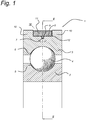
- Figure 1 shows an axial cross-section of a bearing 1 comprising an inner bearing ring 2 having an inner raceway 5, and an outer bearing ring 3 having an outer raceway 6.
- rolling elements 4 are provided such that the inner and outer bearing rings 2, 3 can rotate with respect to each other.
- the rolling elements 4 are located in between the inner and outer raceways 5, 6.
- a groove 7 is provided at an outer surface 8 of the outer bearing ring 3.
- the groove 7 accommodates a fibre sensor 9, comprising an optical fibre.
- the groove 7 is provided within a channel 12.
- the channel 12 is shaped as a recess between two sidewalls 10 forming an increase in thickness of the outer bearing ring 3.
- the fibre sensor 9 is accommodated in the groove 7 and connected to the outer bearing ring by means of a clamping ring 11.
- the clamping ring 11 is accommodated in the channel 12. Clamping ring 11 exerts a clamping force CF onto the fibre sensor 9, as shown in Figure 3 .
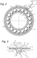
- Figure 2 shows a radial cross-section of the bearing 1.
- the clamping ring 11 is provided around a large part of the circumference of the outer bearing ring 3, except for a relatively small portion forming an opening 13, which is used for placing the clamping ring 11 over the fibre sensor 9 and into the channel 12.
- the fibre sensor 9 is accommodated within the groove 7, over essentially the full circumference of the outer bearing ring 3 from a first end 14 to a second end 15.
- the second end 15 extends from the bearing 1 and can be connected to a suitable detector assembly 30.
- the bearing 1 is manufactured by providing the groove 7 in the outer surface 8 of the outer bearing ring 3.
- the groove 7 has a tapered cross-section extending into the outer bearing ring 3, from the outer surface 8.
- the fibre sensor 9 is put in the groove 7, upon which the clamping ring 11 is snapped over the outer bearing ring 3.
- a temporary fixation can be provided, such as a glue that evaporates or disintegrates during the remainder of the assembly process. When the bearing 1 is ready for use, this temporary fixation should preferably have disappeared, such that a direct contact between the fibre sensor 9 and the groove 7 is established.
- the fibre sensor 9 comprises an optical fibre with fibre Bragg gratings 19.
- the fibre Bragg grating is therefore used as an inline wavelength-specific reflector. Operation of such a sensor is generally conventional and will not be discussed further in the present application.
- FIG 3 shows a detail of the bearing 1 of Figure 1 indicated by III.
- the tapered shape of the groove 7 is clearly shown.
- the width of the entry 16 of the groove 7 is larger than the diameter D of the fibre sensor 9, which in turn is wider than a base 21 of the groove 7.
- the groove 7 and fibre 9 are dimensioned specifically such that on insertion of the fibre 9 into the groove 7, the inner surface 20 of the clamping ring 11 is tangential to the periphery 18 of the fibre 9.
- a clamping force CF is exerted onto the fibre sensor 9. Due to the inclined sidewalls 17 of the groove 7, the clamping force CF has an axial component A and a radial component R.
- FIG. 4 shows a bearing 101 according to an alternative embodiment of the invention in axial cross-section with an alternative clamping ring 111.
- Clamping ring 111 is distinguished from that of the first embodiment by a pair of shoulders 112 extending around the inner circumference. As can be seen in Figure 4 , the shoulders 112 serve to determine the degree of clamping of the fibre sensor 9. The fibre sensor 9 is thus partially received in groove 107 and partially received by the recessed inner surface 120 of the clamping ring 111. It will be understood that other shapes of clamping element and channel may be provided to achieve the same effect.
- FIG 5 shows the bearing 1 of Figures 1 to 3 in perspective view with a number of different clamping rings.
- Clamping ring 111 as shown in Figure 4 is formed to have an opening 113 allowing the ring 111 to be slipped over the outer bearing ring 3 and into the channel 12. Clamping takes place by the inherent spring properties of the ring 111, which is made of spring steel.
- Clamping ring 211 is a complete circumferential ring made of elastic material. It can be slipped over the outer bearing ring 3 by stretching and is retained in the channel 12 by its natural resilience.
- Clamping ring 311 is of a screw clamp type, having a pair of flanges 314, that can be drawn to each other by a screw 315. It will be understood that the clamping ring 311 and bearing 1 are shown schematically and that in reality, the flanges 314 will be of a size that they fit within the channel 12.
- Clamping ring 411 is of a hose clamp type, having a captive screw 415 that engages with thread sections 414 formed along the ring 411.
- Clamping ring 511 is of a cable-tie type. It is formed of plastic and has a ratchet element 515 that engages with serrations 514 formed on the inner surface of the ring 511.
- the skilled person will recognise that many other alternative forms of clamping ring may be implemented.
Landscapes
- Physics & Mathematics (AREA)
- General Physics & Mathematics (AREA)
- Engineering & Computer Science (AREA)
- General Engineering & Computer Science (AREA)
- Mechanical Engineering (AREA)
- Chemical & Material Sciences (AREA)
- Analytical Chemistry (AREA)
- Rolling Contact Bearings (AREA)
Claims (15)
- Palier comprenant une bague de palier supportant une pluralité d'éléments roulants, la bague de palier présentant une surface extérieure et une rainure autour d'une circonférence de la surface extérieure pour recevoir un capteur à fibre, le palier comprenant en outre un élément de serrage, qui engage le capteur à fibre avec une force de serrage qui agit dans une direction radiale de la bague de palier de telle sorte que le capteur à fibre engage de façon intime la bague de palier.
- Palier selon la revendication 1, dans lequel la bague de palier comprend un canal pour recevoir l'élément de serrage, la rainure étant située à l'intérieur du canal.
- Palier selon la revendication 1 ou 2, dans lequel la rainure présente une entrée dont la largeur est égale ou supérieure à un diamètre du capteur à fibre, dans lequel la largeur de la rainure diminue avec l'augmentation de la profondeur, de telle sorte qu'une force de serrage sur le capteur à fibre exercée par l'élément de serrage dans une direction axiale de la bague de palier soit obtenue.
- Palier selon la revendication 3, dans lequel au moins une partie de la largeur de la rainure diminue de façon linéaire avec la profondeur.
- Palier selon la revendication 3 ou 4, dans lequel au moins une partie de la largeur de la rainure diminue avec la profondeur d'une manière parabolique.
- Palier selon l'une quelconque des revendications précédentes, dans lequel le capteur à fibre est une fibre optique.
- Palier selon la revendication 6, dans lequel la fibre optique comprend un capteur à réseau de Bragg sur fibre (FBG).
- Palier selon l'une quelconque des revendications précédentes, dans lequel l'élément de serrage comprend un anneau de serrage.
- Procédé pour connecter un capteur à fibre à un palier, comprenant une bague de palier et des éléments roulants, dans lequel la bague de palier présente une surface extérieure, le procédé comprenant les étapes suivantes:- former une rainure le long d'au moins une partie d'une circonférence de la surface extérieure de la bague de palier, la rainure présentant une dimension de largeur parallèle à une direction axiale de la bague de palier et une dimension de profondeur parallèle à une direction radiale de la bague de palier,- insérer un capteur à fibre dans au moins une partie de la rainure, et- serrer de façon mécanique le capteur à fibre à l'intérieur de la rainure, de telle sorte que le capteur à fibre engage de façon intime la bague de palier avec une force de serrage exercée sur cette partie de la rainure dans laquelle il est inséré.
- Procédé selon la revendication 9, comprenant en outre la fourniture d'un élément de serrage pour serrer le capteur à fibre dans la rainure, de préférence un anneau de serrage.
- Procédé selon la revendication 10, comprenant la formation d'un canal autour d'au moins une partie de la circonférence de la surface extérieure de la bague de palier, dans lequel la rainure est formée dans le canal et l'élément de serrage est reçu dans le canal.
- Procédé selon l'une quelconque des revendications 9 à 11, comprenant la formation d'une rainure présentant une entrée dont la largeur est égale ou supérieure à un diamètre du capteur à fibre, dans lequel la largeur de la rainure diminue avec la profondeur, de telle sorte que la force de serrage exercée sur le capteur à fibre agisse dans une direction radiale du capteur à fibre.
- Procédé selon la revendication 12, dans lequel la forme de la section transversale de la rainure est soit un V, soit un trapézoïde isocèle, soit une semi-ellipse, soit une combinaison de celles-ci.
- Procédé selon l'une quelconque des revendications 9 à 13, dans lequel le capteur à fibre est une fibre optique.
- Procédé selon la revendication 14, dans lequel la fibre optique comprend un capteur à réseau de Bragg sur fibre (FBG).
Applications Claiming Priority (1)
| Application Number | Priority Date | Filing Date | Title |
|---|---|---|---|
| PCT/EP2012/075555 WO2014090332A1 (fr) | 2012-12-14 | 2012-12-14 | Ensemble capteur à fibre |
Publications (2)
| Publication Number | Publication Date |
|---|---|
| EP2932223A1 EP2932223A1 (fr) | 2015-10-21 |
| EP2932223B1 true EP2932223B1 (fr) | 2017-02-15 |
Family
ID=47559386
Family Applications (1)
| Application Number | Title | Priority Date | Filing Date |
|---|---|---|---|
| EP12815655.1A Not-in-force EP2932223B1 (fr) | 2012-12-14 | 2012-12-14 | Ensemble capteur à fibre |
Country Status (4)
| Country | Link |
|---|---|
| US (1) | US9546690B2 (fr) |
| EP (1) | EP2932223B1 (fr) |
| CN (1) | CN105122025A (fr) |
| WO (1) | WO2014090332A1 (fr) |
Families Citing this family (18)
| Publication number | Priority date | Publication date | Assignee | Title |
|---|---|---|---|---|
| CN104380074A (zh) * | 2012-06-15 | 2015-02-25 | Skf公司 | 机械装置 |
| US10428871B2 (en) * | 2014-12-19 | 2019-10-01 | Aktiebolaget Skf | Bearing ring |
| DE102017218878A1 (de) * | 2016-11-07 | 2018-05-24 | Aktiebolaget Skf | Verkabeltes Lager |
| CN108318248B (zh) * | 2017-01-16 | 2021-09-28 | 舍弗勒技术股份两合公司 | 基于光纤振动传感的轴承状态在线监测系统 |
| FR3067074B1 (fr) * | 2017-06-02 | 2019-07-26 | Skf Aerospace France | Ensemble de roulement instrumente |
| CN107870052B (zh) * | 2017-10-20 | 2020-01-31 | 重庆大学 | 一种微型光纤法珀压力传感器 |
| DE102018214195A1 (de) | 2018-08-22 | 2020-03-19 | Aktiebolaget Skf | Verfahren zum Befestigen einer Faser mit einem Faser-Bragg-Sensorsegment an eine Komponente oder Lagervorrichtung mit einer derartigen Faser |
| CN109990723B (zh) * | 2018-11-30 | 2021-01-12 | 东莞理工学院 | 一种可重复使用的埋入式光栅测量装置 |
| CN111853071B (zh) * | 2019-04-11 | 2024-09-03 | 斯凯孚公司 | 一种滚子轴承、风力涡轮机和风力涡轮机的控制方法 |
| DE102019109939A1 (de) * | 2019-04-15 | 2020-10-15 | Bayerische Motoren Werke Aktiengesellschaft | Einrichtung zur Visualisierung von Auslenkungen eines Elastomerlagers |
| DE102019116999A1 (de) * | 2019-06-25 | 2020-12-31 | Schaeffler Technologies AG & Co. KG | Rollenlageranordnung zum Bestimmen von Belastungen |
| CN110645266B (zh) * | 2019-06-26 | 2020-11-27 | 扬州市舜意机械有限公司 | 一种传感一体化的关节轴承及其使用方法 |
| DE102019209910A1 (de) * | 2019-07-05 | 2021-01-07 | Aktiebolaget Skf | Wälzlager mit integriertem Glasfasersensor |
| DE102019214488A1 (de) | 2019-09-23 | 2021-03-25 | Aktiebolaget Skf | Lager mit einer einzelnen optischen Messfaser zur Lasterfassung und Lagereinheit mit kombinierten Lagern |
| DE102020103421A1 (de) | 2020-02-11 | 2021-08-12 | Liebherr-Components Biberach Gmbh | Wälzlager mit Überwachungsvorrichtung |
| DE102020208508A1 (de) * | 2020-07-07 | 2022-01-13 | Aktiebolaget Skf | Lagerring mit integriertem Fasersensor und zugehörigem Lager |
| US12352650B2 (en) * | 2021-12-07 | 2025-07-08 | Aktiebolaget Skf | Device equipped with an optical sensing element for sensing axial loads, notably for a bearing |
| DE102024101658A1 (de) * | 2024-01-22 | 2025-07-24 | Schaeffler Technologies AG & Co. KG | Radlagereinheit zur Lagerung eines Fahrzeugrades mit einer Messvorrichtung und Verfahren zur Montage einer Messvorrichtung |
Family Cites Families (20)
| Publication number | Priority date | Publication date | Assignee | Title |
|---|---|---|---|---|
| JPS6346407A (ja) * | 1987-08-07 | 1988-02-27 | Mirai Ind Co Ltd | 光ファイバ−接続具 |
| FR2626631B1 (fr) * | 1988-01-29 | 1994-03-25 | Snr Roulements | Montage de palier a roulement avec dispositif capteur |
| DE3940777A1 (de) * | 1989-12-06 | 1991-06-13 | Siemens Ag | Verfahren zum herstellen einer spleissvorrichtung fuer zwei optische fasern |
| FR2673713B1 (fr) * | 1991-03-07 | 1993-06-25 | Framatome Sa | Capteur optique, en particulier capteur de pression et procede de mesure optique correspondant. |
| JPH1082428A (ja) * | 1996-07-17 | 1998-03-31 | Nippon Seiko Kk | 転がり軸受のクリープ防止装置 |
| US6080982A (en) * | 1998-05-13 | 2000-06-27 | The United States Of America As Represented By The Secretary Of The Navy | Embedded wear sensor |
| US6948856B2 (en) * | 2000-11-06 | 2005-09-27 | Nsk Ltd. | Rolling bearing device and ring with sensor for the rolling bearing device |
| US20030113090A1 (en) * | 2001-12-18 | 2003-06-19 | Lee Nicholas A. | Method for aligning a plurality of optical fibers in a parallel array |
| DE10303876A1 (de) * | 2003-01-31 | 2004-08-12 | Fag Kugelfischer Ag | Messanordnung, Wälzlager und Verfahren zur Ermittlung der Bewegungsrichtung eines Wälzlagerbauteils |
| DE10304592A1 (de) * | 2003-02-05 | 2004-08-19 | Fag Kugelfischer Ag | Messlager mit integriertem Datenerfassungs- und verarbeitungssystems |
| JP2005291287A (ja) * | 2004-03-31 | 2005-10-20 | Koyo Seiko Co Ltd | センサ付転がり軸受 |
| JP2006343402A (ja) * | 2005-06-07 | 2006-12-21 | Olympus Medical Systems Corp | 光ファイバー束及びその製造方法 |
| US7240570B2 (en) * | 2005-09-06 | 2007-07-10 | The Timken Company | Load-sensing bearing |
| GB2457277B (en) | 2008-02-08 | 2010-10-13 | Schlumberger Holdings | Methods and apparatus for detecting strain in structures |
| WO2010043699A1 (fr) * | 2008-10-16 | 2010-04-22 | Siemens Aktiengesellschaft | Dispositif de surveillance de roulement |
| DE102008061553B4 (de) | 2008-12-11 | 2018-03-01 | Prüftechnik Dieter Busch AG | Verfahren und Vorrichtung zur dynamischen Messung der radialen Deformation eines Wälzlagerrings |
| US8790013B2 (en) * | 2009-12-04 | 2014-07-29 | Aktiebolaget Skf | Bearing monitoring using a fibre bragg grating |
| CN201772884U (zh) * | 2010-09-02 | 2011-03-23 | 中国地震局地壳应力研究所 | 一种压板式光纤光栅传感器 |
| CN102519381A (zh) * | 2011-12-19 | 2012-06-27 | 广州南洋理工职业学院 | 微弯式强度调制型光纤传感器 |
| CN202563119U (zh) * | 2012-03-31 | 2012-11-28 | 成都捷康特科技有限公司 | 一种切割定位式光纤熔接机 |
-
2012
- 2012-12-14 CN CN201280078114.7A patent/CN105122025A/zh active Pending
- 2012-12-14 WO PCT/EP2012/075555 patent/WO2014090332A1/fr not_active Ceased
- 2012-12-14 US US14/652,233 patent/US9546690B2/en not_active Expired - Fee Related
- 2012-12-14 EP EP12815655.1A patent/EP2932223B1/fr not_active Not-in-force
Non-Patent Citations (1)
| Title |
|---|
| None * |
Also Published As
| Publication number | Publication date |
|---|---|
| US20150323013A1 (en) | 2015-11-12 |
| US9546690B2 (en) | 2017-01-17 |
| EP2932223A1 (fr) | 2015-10-21 |
| CN105122025A (zh) | 2015-12-02 |
| WO2014090332A1 (fr) | 2014-06-19 |
Similar Documents
| Publication | Publication Date | Title |
|---|---|---|
| EP2932223B1 (fr) | Ensemble capteur à fibre | |
| US8790013B2 (en) | Bearing monitoring using a fibre bragg grating | |
| WO2014090324A1 (fr) | Ensemble capteur à fibre optique | |
| US10352364B2 (en) | State detector for roller bearing and roller bearing device | |
| JP7549578B2 (ja) | 測定ロールを介してガイドされる帯状の物品の特性を検出するための測定ロール | |
| JP7628950B2 (ja) | 測定ロールを介してガイドされる帯状の物品の特性を検出するための方法 | |
| US11656150B2 (en) | Rolling bearing with integrated optical fiber sensor | |
| WO2014108170A1 (fr) | Attache pour capteur à fibre optique | |
| EP3722628B1 (fr) | Roulement à rouleaux, éolienne et méthode pour sa régulation | |
| CN112539221B (zh) | 具有用于载荷感测的单个感测光纤的轴承和轴承单元 | |
| JP2015529803A (ja) | トルクを測定するためのシステムおよび方法 | |
| JP2009216665A (ja) | 外輪へのひずみセンサ内蔵型転がり軸受の荷重分布測定方法及びその装置 | |
| CN211205608U (zh) | 螺栓组件及检测螺栓受力的系统 | |
| JP5621440B2 (ja) | 光ファイバ用巻取りボビン | |
| CN113898666A (zh) | 具有集成纤维传感器的轴承圈和相关联的轴承 | |
| CN108759681A (zh) | 光纤光栅传感器 | |
| US12352650B2 (en) | Device equipped with an optical sensing element for sensing axial loads, notably for a bearing | |
| JP4656995B2 (ja) | 回転体装置 | |
| CN117685299A (zh) | 具有距离传感器的滚动轴承 | |
| JP2009128009A (ja) | 光ファイバセンサ | |
| GB2576167A (en) | Sensing assembly for bearing and mounting method |
Legal Events
| Date | Code | Title | Description |
|---|---|---|---|
| PUAI | Public reference made under article 153(3) epc to a published international application that has entered the european phase |
Free format text: ORIGINAL CODE: 0009012 |
|
| 17P | Request for examination filed |
Effective date: 20150528 |
|
| AK | Designated contracting states |
Kind code of ref document: A1 Designated state(s): AL AT BE BG CH CY CZ DE DK EE ES FI FR GB GR HR HU IE IS IT LI LT LU LV MC MK MT NL NO PL PT RO RS SE SI SK SM TR |
|
| AX | Request for extension of the european patent |
Extension state: BA ME |
|
| DAX | Request for extension of the european patent (deleted) | ||
| GRAP | Despatch of communication of intention to grant a patent |
Free format text: ORIGINAL CODE: EPIDOSNIGR1 |
|
| INTG | Intention to grant announced |
Effective date: 20160831 |
|
| GRAS | Grant fee paid |
Free format text: ORIGINAL CODE: EPIDOSNIGR3 |
|
| GRAA | (expected) grant |
Free format text: ORIGINAL CODE: 0009210 |
|
| AK | Designated contracting states |
Kind code of ref document: B1 Designated state(s): AL AT BE BG CH CY CZ DE DK EE ES FI FR GB GR HR HU IE IS IT LI LT LU LV MC MK MT NL NO PL PT RO RS SE SI SK SM TR |
|
| REG | Reference to a national code |
Ref country code: CH Ref legal event code: EP Ref country code: GB Ref legal event code: FG4D |
|
| REG | Reference to a national code |
Ref country code: IE Ref legal event code: FG4D |
|
| REG | Reference to a national code |
Ref country code: AT Ref legal event code: REF Ref document number: 868178 Country of ref document: AT Kind code of ref document: T Effective date: 20170315 |
|
| REG | Reference to a national code |
Ref country code: DE Ref legal event code: R096 Ref document number: 602012028772 Country of ref document: DE |
|
| REG | Reference to a national code |
Ref country code: NL Ref legal event code: MP Effective date: 20170215 |
|
| REG | Reference to a national code |
Ref country code: LT Ref legal event code: MG4D |
|
| REG | Reference to a national code |
Ref country code: AT Ref legal event code: MK05 Ref document number: 868178 Country of ref document: AT Kind code of ref document: T Effective date: 20170215 |
|
| PG25 | Lapsed in a contracting state [announced via postgrant information from national office to epo] |
Ref country code: NO Free format text: LAPSE BECAUSE OF FAILURE TO SUBMIT A TRANSLATION OF THE DESCRIPTION OR TO PAY THE FEE WITHIN THE PRESCRIBED TIME-LIMIT Effective date: 20170515 Ref country code: FI Free format text: LAPSE BECAUSE OF FAILURE TO SUBMIT A TRANSLATION OF THE DESCRIPTION OR TO PAY THE FEE WITHIN THE PRESCRIBED TIME-LIMIT Effective date: 20170215 Ref country code: LT Free format text: LAPSE BECAUSE OF FAILURE TO SUBMIT A TRANSLATION OF THE DESCRIPTION OR TO PAY THE FEE WITHIN THE PRESCRIBED TIME-LIMIT Effective date: 20170215 Ref country code: GR Free format text: LAPSE BECAUSE OF FAILURE TO SUBMIT A TRANSLATION OF THE DESCRIPTION OR TO PAY THE FEE WITHIN THE PRESCRIBED TIME-LIMIT Effective date: 20170516 Ref country code: HR Free format text: LAPSE BECAUSE OF FAILURE TO SUBMIT A TRANSLATION OF THE DESCRIPTION OR TO PAY THE FEE WITHIN THE PRESCRIBED TIME-LIMIT Effective date: 20170215 |
|
| PG25 | Lapsed in a contracting state [announced via postgrant information from national office to epo] |
Ref country code: RS Free format text: LAPSE BECAUSE OF FAILURE TO SUBMIT A TRANSLATION OF THE DESCRIPTION OR TO PAY THE FEE WITHIN THE PRESCRIBED TIME-LIMIT Effective date: 20170215 Ref country code: AT Free format text: LAPSE BECAUSE OF FAILURE TO SUBMIT A TRANSLATION OF THE DESCRIPTION OR TO PAY THE FEE WITHIN THE PRESCRIBED TIME-LIMIT Effective date: 20170215 Ref country code: PT Free format text: LAPSE BECAUSE OF FAILURE TO SUBMIT A TRANSLATION OF THE DESCRIPTION OR TO PAY THE FEE WITHIN THE PRESCRIBED TIME-LIMIT Effective date: 20170615 Ref country code: ES Free format text: LAPSE BECAUSE OF FAILURE TO SUBMIT A TRANSLATION OF THE DESCRIPTION OR TO PAY THE FEE WITHIN THE PRESCRIBED TIME-LIMIT Effective date: 20170215 Ref country code: LV Free format text: LAPSE BECAUSE OF FAILURE TO SUBMIT A TRANSLATION OF THE DESCRIPTION OR TO PAY THE FEE WITHIN THE PRESCRIBED TIME-LIMIT Effective date: 20170215 Ref country code: SE Free format text: LAPSE BECAUSE OF FAILURE TO SUBMIT A TRANSLATION OF THE DESCRIPTION OR TO PAY THE FEE WITHIN THE PRESCRIBED TIME-LIMIT Effective date: 20170215 Ref country code: BG Free format text: LAPSE BECAUSE OF FAILURE TO SUBMIT A TRANSLATION OF THE DESCRIPTION OR TO PAY THE FEE WITHIN THE PRESCRIBED TIME-LIMIT Effective date: 20170515 Ref country code: NL Free format text: LAPSE BECAUSE OF NON-PAYMENT OF DUE FEES Effective date: 20170215 |
|
| PG25 | Lapsed in a contracting state [announced via postgrant information from national office to epo] |
Ref country code: IT Free format text: LAPSE BECAUSE OF FAILURE TO SUBMIT A TRANSLATION OF THE DESCRIPTION OR TO PAY THE FEE WITHIN THE PRESCRIBED TIME-LIMIT Effective date: 20170215 Ref country code: RO Free format text: LAPSE BECAUSE OF FAILURE TO SUBMIT A TRANSLATION OF THE DESCRIPTION OR TO PAY THE FEE WITHIN THE PRESCRIBED TIME-LIMIT Effective date: 20170215 Ref country code: CZ Free format text: LAPSE BECAUSE OF FAILURE TO SUBMIT A TRANSLATION OF THE DESCRIPTION OR TO PAY THE FEE WITHIN THE PRESCRIBED TIME-LIMIT Effective date: 20170215 Ref country code: SK Free format text: LAPSE BECAUSE OF FAILURE TO SUBMIT A TRANSLATION OF THE DESCRIPTION OR TO PAY THE FEE WITHIN THE PRESCRIBED TIME-LIMIT Effective date: 20170215 Ref country code: EE Free format text: LAPSE BECAUSE OF FAILURE TO SUBMIT A TRANSLATION OF THE DESCRIPTION OR TO PAY THE FEE WITHIN THE PRESCRIBED TIME-LIMIT Effective date: 20170215 |
|
| REG | Reference to a national code |
Ref country code: DE Ref legal event code: R097 Ref document number: 602012028772 Country of ref document: DE |
|
| PG25 | Lapsed in a contracting state [announced via postgrant information from national office to epo] |
Ref country code: DK Free format text: LAPSE BECAUSE OF FAILURE TO SUBMIT A TRANSLATION OF THE DESCRIPTION OR TO PAY THE FEE WITHIN THE PRESCRIBED TIME-LIMIT Effective date: 20170215 Ref country code: SM Free format text: LAPSE BECAUSE OF FAILURE TO SUBMIT A TRANSLATION OF THE DESCRIPTION OR TO PAY THE FEE WITHIN THE PRESCRIBED TIME-LIMIT Effective date: 20170215 Ref country code: PL Free format text: LAPSE BECAUSE OF FAILURE TO SUBMIT A TRANSLATION OF THE DESCRIPTION OR TO PAY THE FEE WITHIN THE PRESCRIBED TIME-LIMIT Effective date: 20170215 |
|
| PLBE | No opposition filed within time limit |
Free format text: ORIGINAL CODE: 0009261 |
|
| STAA | Information on the status of an ep patent application or granted ep patent |
Free format text: STATUS: NO OPPOSITION FILED WITHIN TIME LIMIT |
|
| 26N | No opposition filed |
Effective date: 20171116 |
|
| PG25 | Lapsed in a contracting state [announced via postgrant information from national office to epo] |
Ref country code: SI Free format text: LAPSE BECAUSE OF FAILURE TO SUBMIT A TRANSLATION OF THE DESCRIPTION OR TO PAY THE FEE WITHIN THE PRESCRIBED TIME-LIMIT Effective date: 20170215 |
|
| REG | Reference to a national code |
Ref country code: CH Ref legal event code: PL |
|
| GBPC | Gb: european patent ceased through non-payment of renewal fee |
Effective date: 20171214 |
|
| REG | Reference to a national code |
Ref country code: IE Ref legal event code: MM4A |
|
| PG25 | Lapsed in a contracting state [announced via postgrant information from national office to epo] |
Ref country code: LU Free format text: LAPSE BECAUSE OF NON-PAYMENT OF DUE FEES Effective date: 20171214 Ref country code: MT Free format text: LAPSE BECAUSE OF NON-PAYMENT OF DUE FEES Effective date: 20171214 |
|
| REG | Reference to a national code |
Ref country code: FR Ref legal event code: ST Effective date: 20180831 |
|
| REG | Reference to a national code |
Ref country code: BE Ref legal event code: MM Effective date: 20171231 |
|
| PG25 | Lapsed in a contracting state [announced via postgrant information from national office to epo] |
Ref country code: FR Free format text: LAPSE BECAUSE OF NON-PAYMENT OF DUE FEES Effective date: 20180102 Ref country code: IE Free format text: LAPSE BECAUSE OF NON-PAYMENT OF DUE FEES Effective date: 20171214 |
|
| PG25 | Lapsed in a contracting state [announced via postgrant information from national office to epo] |
Ref country code: BE Free format text: LAPSE BECAUSE OF NON-PAYMENT OF DUE FEES Effective date: 20171231 Ref country code: CH Free format text: LAPSE BECAUSE OF NON-PAYMENT OF DUE FEES Effective date: 20171231 Ref country code: GB Free format text: LAPSE BECAUSE OF NON-PAYMENT OF DUE FEES Effective date: 20171214 Ref country code: LI Free format text: LAPSE BECAUSE OF NON-PAYMENT OF DUE FEES Effective date: 20171231 |
|
| PGFP | Annual fee paid to national office [announced via postgrant information from national office to epo] |
Ref country code: DE Payment date: 20190228 Year of fee payment: 7 |
|
| PG25 | Lapsed in a contracting state [announced via postgrant information from national office to epo] |
Ref country code: HU Free format text: LAPSE BECAUSE OF FAILURE TO SUBMIT A TRANSLATION OF THE DESCRIPTION OR TO PAY THE FEE WITHIN THE PRESCRIBED TIME-LIMIT; INVALID AB INITIO Effective date: 20121214 Ref country code: MC Free format text: LAPSE BECAUSE OF FAILURE TO SUBMIT A TRANSLATION OF THE DESCRIPTION OR TO PAY THE FEE WITHIN THE PRESCRIBED TIME-LIMIT Effective date: 20170215 |
|
| PG25 | Lapsed in a contracting state [announced via postgrant information from national office to epo] |
Ref country code: CY Free format text: LAPSE BECAUSE OF FAILURE TO SUBMIT A TRANSLATION OF THE DESCRIPTION OR TO PAY THE FEE WITHIN THE PRESCRIBED TIME-LIMIT Effective date: 20170215 |
|
| PG25 | Lapsed in a contracting state [announced via postgrant information from national office to epo] |
Ref country code: MK Free format text: LAPSE BECAUSE OF FAILURE TO SUBMIT A TRANSLATION OF THE DESCRIPTION OR TO PAY THE FEE WITHIN THE PRESCRIBED TIME-LIMIT Effective date: 20170215 |
|
| PG25 | Lapsed in a contracting state [announced via postgrant information from national office to epo] |
Ref country code: TR Free format text: LAPSE BECAUSE OF FAILURE TO SUBMIT A TRANSLATION OF THE DESCRIPTION OR TO PAY THE FEE WITHIN THE PRESCRIBED TIME-LIMIT Effective date: 20170215 |
|
| REG | Reference to a national code |
Ref country code: DE Ref legal event code: R119 Ref document number: 602012028772 Country of ref document: DE |
|
| PG25 | Lapsed in a contracting state [announced via postgrant information from national office to epo] |
Ref country code: AL Free format text: LAPSE BECAUSE OF FAILURE TO SUBMIT A TRANSLATION OF THE DESCRIPTION OR TO PAY THE FEE WITHIN THE PRESCRIBED TIME-LIMIT Effective date: 20170215 Ref country code: IS Free format text: LAPSE BECAUSE OF FAILURE TO SUBMIT A TRANSLATION OF THE DESCRIPTION OR TO PAY THE FEE WITHIN THE PRESCRIBED TIME-LIMIT Effective date: 20170615 |
|
| PG25 | Lapsed in a contracting state [announced via postgrant information from national office to epo] |
Ref country code: DE Free format text: LAPSE BECAUSE OF NON-PAYMENT OF DUE FEES Effective date: 20200701 |