EP2932485B1 - Système et procédé de collecte de données portables - Google Patents
Système et procédé de collecte de données portables Download PDFInfo
- Publication number
- EP2932485B1 EP2932485B1 EP13863062.9A EP13863062A EP2932485B1 EP 2932485 B1 EP2932485 B1 EP 2932485B1 EP 13863062 A EP13863062 A EP 13863062A EP 2932485 B1 EP2932485 B1 EP 2932485B1
- Authority
- EP
- European Patent Office
- Prior art keywords
- tag
- data collector
- mobile data
- rfid tags
- machines
- Prior art date
- Legal status (The legal status is an assumption and is not a legal conclusion. Google has not performed a legal analysis and makes no representation as to the accuracy of the status listed.)
- Active
Links
Images


Classifications
-
- G—PHYSICS
- G06—COMPUTING OR CALCULATING; COUNTING
- G06K—GRAPHICAL DATA READING; PRESENTATION OF DATA; RECORD CARRIERS; HANDLING RECORD CARRIERS
- G06K7/00—Methods or arrangements for sensing record carriers, e.g. for reading patterns
- G06K7/10—Methods or arrangements for sensing record carriers, e.g. for reading patterns by electromagnetic radiation, e.g. optical sensing; by corpuscular radiation
- G06K7/10009—Methods or arrangements for sensing record carriers, e.g. for reading patterns by electromagnetic radiation, e.g. optical sensing; by corpuscular radiation sensing by radiation using wavelengths larger than 0.1 mm, e.g. radio-waves or microwaves
- G06K7/10366—Methods or arrangements for sensing record carriers, e.g. for reading patterns by electromagnetic radiation, e.g. optical sensing; by corpuscular radiation sensing by radiation using wavelengths larger than 0.1 mm, e.g. radio-waves or microwaves the interrogation device being adapted for miscellaneous applications
-
- G—PHYSICS
- G05—CONTROLLING; REGULATING
- G05B—CONTROL OR REGULATING SYSTEMS IN GENERAL; FUNCTIONAL ELEMENTS OF SUCH SYSTEMS; MONITORING OR TESTING ARRANGEMENTS FOR SUCH SYSTEMS OR ELEMENTS
- G05B19/00—Program-control systems
- G05B19/02—Program-control systems electric
- G05B19/418—Total factory control, i.e. centrally controlling a plurality of machines, e.g. direct or distributed numerical control [DNC], flexible manufacturing systems [FMS], integrated manufacturing systems [IMS] or computer integrated manufacturing [CIM]
- G05B19/4183—Total factory control, i.e. centrally controlling a plurality of machines, e.g. direct or distributed numerical control [DNC], flexible manufacturing systems [FMS], integrated manufacturing systems [IMS] or computer integrated manufacturing [CIM] characterised by data acquisition, e.g. workpiece identification
-
- G—PHYSICS
- G05—CONTROLLING; REGULATING
- G05B—CONTROL OR REGULATING SYSTEMS IN GENERAL; FUNCTIONAL ELEMENTS OF SUCH SYSTEMS; MONITORING OR TESTING ARRANGEMENTS FOR SUCH SYSTEMS OR ELEMENTS
- G05B2219/00—Program-control systems
- G05B2219/30—Nc systems
- G05B2219/33—Director till display
- G05B2219/33192—Radio link, wireless
-
- G—PHYSICS
- G05—CONTROLLING; REGULATING
- G05B—CONTROL OR REGULATING SYSTEMS IN GENERAL; FUNCTIONAL ELEMENTS OF SUCH SYSTEMS; MONITORING OR TESTING ARRANGEMENTS FOR SUCH SYSTEMS OR ELEMENTS
- G05B2219/00—Program-control systems
- G05B2219/30—Nc systems
- G05B2219/49—Nc machine tool, till multiple
- G05B2219/49302—Part, workpiece, code, tool identification
-
- Y—GENERAL TAGGING OF NEW TECHNOLOGICAL DEVELOPMENTS; GENERAL TAGGING OF CROSS-SECTIONAL TECHNOLOGIES SPANNING OVER SEVERAL SECTIONS OF THE IPC; TECHNICAL SUBJECTS COVERED BY FORMER USPC CROSS-REFERENCE ART COLLECTIONS [XRACs] AND DIGESTS
- Y02—TECHNOLOGIES OR APPLICATIONS FOR MITIGATION OR ADAPTATION AGAINST CLIMATE CHANGE
- Y02P—CLIMATE CHANGE MITIGATION TECHNOLOGIES IN THE PRODUCTION OR PROCESSING OF GOODS
- Y02P90/00—Enabling technologies with a potential contribution to greenhouse gas [GHG] emissions mitigation
- Y02P90/02—Total factory control, e.g. smart factories, flexible manufacturing systems [FMS] or integrated manufacturing systems [IMS]
Definitions
- the present disclosure relates to management of data collection, e.g., of operating conditions of a machine.
- Data is often collected to monitor the operation of industrial machines. Such data collection may be used to diagnose problems, troubleshoot, trend operating changes, or otherwise record data points indicative of machine operation.
- a variety of data types may be collected, including temperature, vibration, and the like.
- the data collection may be continuous, i.e., using dedicated resources for individual machines or groups of machines. In other cases, data collection may be on-demand, for example, in routine checking and maintenance of the machines. In the latter case, mobile units may be provided that use sensors that are either permanently or temporarily coupled with the machine being measured.
- Such a data collection system is known from document US 2008/201388 A1 .
- Such on-demand data collection may, however, be costly in terms of time and resources. For example, if several machines are being checked using a mobile unit, complexity in the operation of the data collection unit may be multiplied and may require significant time allocation. Further, bulkiness of such units may hinder movement between machines being measured. However, a reduction in unit size may reduce functionality, such as the ability to retain measurements from previous operations, execute data collection/management software, etc. Complexity may also introduce the possibility of human error, and thus resources may be expended in training users to operate the units.
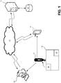
- FIG. 1 illustrates a schematic view of a system 100 for collecting and/or managing data, according to an embodiment.
- the system 100 may include a mobile data collector 102 configured to collect data related to a machine 104.
- the mobile data collector 102 may include one or more sensors, probes, or the like.
- the mobile data collector 102 may include a temperature sensor such as a thermistor, thermocouple, infrared sensor, or the like, a velocity sensor, an accelerometer, a vibration sensor, a potentiometer, an ammeter, an ohmmeter, a magnetic field sensor, and/or any other suitable type of sensor configured to collect any type of data characterizing operation of the machine 104.
- the mobile data collector 102 may be configured to measure multiple types of operating conditions (e.g., temperature and vibration) simultaneously, sequentially, selectively, or a combination thereof.
- the machine 104 may represent any number of machines with which teh system 100 may be employed or may include.
- the machines 104 may be rotary machines, such as compressors, pumps, turbines, gensets, engines, motors, or the like. In other embodiments, the machines 104 may be any other type of machine. Further, the machines 104 may be organized as a "route," i.e., a planned or preselected sequence or progression of machines 104 to be measured using the mobile data collector 102 (e.g., as part of a session).
- the mobile data collector 102 may also include a tag reader configured to read a tag identifier (ID) from one or more radio frequency identification (RFID) tags (two are shown: 106, 108).
- ID tag identifier
- RFID radio frequency identification
- the mobile data collector 102 may include an inductor configured to energize passive RFID tags 106, 108, when the mobile data collector 102 is brought into proximity therewith, and thereby read data such as the tag ID from the RFID tags 106, 108.
- the RFID tags 106, 108 may be active RFID tags, which may transmit data to the mobile data collector 102 without requiring the mobile data collector 102 to provide the energizing.
- the RFID tags 106, 108 may be coupled with a single machine 104. In various cases, one, three, or more RFID tags 106, 108 may be coupled with a single machine 104. Further, each of the RFID tags 106, 108 may be associated with a location of (e.g., on, within, etc.) the machine 104. The location may be at or near a point where measurements are to be collected, such as a shaft, bearing housing, and/or other components for which monitoring the operating conditions is useful.
- multiple RFID tags 106, 108 may be associated with the same machine 104, while multiple RFID tags 106, 108 may be associated with the same location on different machines; however, in at least one embodiment, the combination of machine 104 identity and location thereof may be unique for each RFID tag 106, 108.
- the mobile data collector 102 is depicted as being proximal to the RFID tag 106 for purposes of illustration.
- proximal In proximity to
- grammatical equivalents are defined to mean “within an effective range,” which may vary according to the devices of the system 100 being discussed and/or the types of devices in various embodiments.
- the RFID tags 106, 108 may be near field communication (NFC) tags, which may have an effective range of one meter or less, or may be another type of RFID tag 106, 108 having a longer range.
- NFC near field communication
- the mobile data collector 102 may be configured to read the tag ID from the RFID tag 106.
- the mobile collector device 102 may then store the tag ID of the RFID tag 106 and take one or more measurements of the operating conditions of the machine 104 in association with the tag ID read.
- the mobile data collector 102 when activated (e.g., in response to actuating an activation switch or button), may be configured to automatically determine when it is in proximity to the RFID tag 106.
- the mobile data collector 102 may display a successful reading of the tag ID from the RFID tag 106, and may automatically commence taking one or more measurements of operating conditions.
- the mobile data collector 102 may be configured to detect when the condition being measured has reached a steady state in the mobile data collector 102, and may take one, some, or all of the measurements at steady state.
- the mobile data collector 102 may also include one or more processors, a display, and memory, for example, to store an internal database of information.
- the processor may be any suitable type of processor and may be configured to communicate with the probe or sensor and the tag reader, so as to at least receive information therefrom.
- the processor may also be coupled with a display. Accordingly, the processor may determine a status of operation of the mobile data collector 102 and/or receive and interpret data collected using the probe/sensor and/or the tag reader, and show the data on the display so the user may read the data, e.g., in real time.
- the display may be any suitable type of display, such as a liquid crystal display (LCD), touchscreen, or the like.
- the mobile data collector 102 may also include an image capture device (camera), audio capture device (microphone), or the like, as well as memory sufficient to record such non-text data.
- the mobile data collector 102 may be configured to extract information (e.g., tag ID, machine identifying information, location information, etc.) from the non-text data. Additionally or alternatively, the mobile data collector 102 may be configured to transmit the non-text data to another device, such that the extraction may be conducted by the other device.
- information e.g., tag ID, machine identifying information, location information, etc.
- the system 100 may also include a host computing device 110, which may be disposed at the same or a different facility or area as the mobile data collector 102.
- the illustrated host computing device 110 may be representative of one or several (e.g., an array of) computing devices, which may be accessed by one or several different entities.
- the host computing device 110 may include a memory, as will be described in greater detail below, which may store thereon a database 112.
- the database 112 may associate tag IDs of each of the RFID tags 106, 108 with information about the machines 104 on or near to which they are attached.
- the database 112 may associate the tag IDs with an identity (e.g., serial number, location, facility, name, etc.) of the machine 104 with the tag IDs of the RFID tags 106, 108. Further, the database 112 may associate the particular location of the RFID tags 106, 108 on the machine 104 with the tag IDs. Additionally, the database 112 may associate the tag ID of each of the RFID tags 106, 108 with acceptable operating conditions for the machine 104 to which the RFID tags 106, 108 are attached. Such acceptable operating conditions may be referred to as an "operating envelope," which may or may not include manufacturer data, factors of safety, other safety requirements or standards, design conditions, operating environment, and/or the like.
- the system 100 may provide for the data (e.g., tag ID and measurements of operating conditions) captured by the mobile data collector 102 to be transmitted to the host computing device 110.
- the mobile collector device 102 may include a radio and/or other hardware and may packetize the measurement with the tag ID and transmit the data to the host computing device 110, for example, via a network 114.
- the network 114 may be a local area network, or wide area network such as the internet, and may be or include wireless connections, wired transmission lines, or both, as well as switches, routers, servers, etc.
- the mobile data collector 102 may provide the measurements to a mobile computing device 116.
- the mobile computing device 116 may also be mobile (e.g., portable), allowing it to be conveniently moved along with the mobile data collector 102.
- the mobile computing device 116 may be or include one or more notebook or laptop computers, tablet devices, smartphones, etc.
- the mobile computing device 116 may communicate with the mobile data collector 102 via a wired connection such as a universal serial bus (USB) connection, Ethernet connection, or the like. Additionally or alternatively, the mobile computing device 116 may communicate with the mobile data collector 102 via a wireless connection, such as a BLUETOOTH® or another wireless protocol.
- the mobile computing device 116 may transmit data received from the mobile data collector 102 to the host computing device 110 via the network 114.
- the mobile computing device 116 may be considered to be part of the mobile data collector 102, whether contained in a single housing or being configured as separate units.
- the host computing device 110 may analyze the data received from the mobile data collector 102 (e.g., by way of the mobile computing device 116). For example, the host computing device 110 may receive the tag ID and access an index of the database 112 associated with the tag ID. The host computing device 110 may then analyze the operation of the machine 104 based on the operating conditions. For example, the host computing device 110 may compare the measurement of the operating conditions with the operating envelope to determine whether the machine 104 is operating within design constraints. Additionally, the host computing device 110 may compute operating trends, diagnose system health, wear, remaining life, etc., based on the conditions and/or using the trends.
- the system 100 may further provide for the display of the results of the analysis by the host computing device 110. In some cases, this may be provided by way of a graphical user interface.
- the graphical user interface may provide intuitive access for a user to view the trends, operating history, etc., as determined by the host computing device 110.
- the graphical user interface may be accessible to a local computing device 120, such as a computer, workstation, or the like. Additionally or alternatively, the graphical user interface may be accessible to the mobile computing device 116. In some cases, different graphical user interfaces may be tailored for use for the mobile computing device 116 and the local computing device 120.
- the local computing device 120 and/or mobile computing device 116 may display the results of the analyses conducted by the host computing device 110, allow for interaction with the results, etc., without having to perform the analyses locally.
- Such an arrangement may be generally known as "cloud computing,” and may combine the computing power and/or storage resources of the host computing device 110 with the convenience of the mobile computing device 116, for example.
- Figure 2 illustrates a flowchart of a method 200 for managing and/or collecting data, according to an embodiment.
- the method 200 may proceed by operation of one or more portions of the system 100 and thus is described reference thereto; however, it will be appreciated that the method 200 is not limited to any particular structure unless otherwise expressly stated herein.
- the method 200 may include a user collecting identifying data for the machines 104, as at 202.
- the identifying data may include the type of machine (e.g., pump, compressor, motor, etc.), manufacturer, serial number, location in a factory, and/or any other relevant data.
- the identifying data may also indicate a location of the machine 104 where measurements are to be taken (e.g., by referencing a particular component of the machine 104, a side of the machine 104, etc.).
- the identifying data may indicate a total number of machines 104 that are to be monitored and/or a total number of locations thereof. If a single location is selected for each machine 104, these two numbers may be the same; however, if the user requires two or more monitoring locations for any of the machines 104, the numbers may differ.
- the method 200 may proceed to the user submitting the identifying data, as at 204, to a supplier.
- Such submitting may proceed by the mobile data collector 102, the mobile computing device 116, and/or the local computing device 120 transmitting the information electronically to the supplier, e.g., to the host computing device 110 provided or controlled by the supplier, via the network 114.
- such electronic transmission may employ electronic mail, a TCP/IP connection, FTP, short message system (SMS), or any other type of or protocol for transmission.
- the identifying data may be transmitted via telephone, written communication, etc.
- the supplier may receive the identifying data, as at 206, for example, using the host computing device 110.
- the supplier may then allocate RFID tags 106, 108 to the submission and associate the machines 104 with the tag IDs of the RFID tags 106, 108, e.g., using the database 112, as at 208.
- the supplier may associate the locations of the machines 104 with the tag IDs. As noted above, the combination of machine identity and location thereon may be unique for each RFID tag 106, 108.
- the supplier may then associate operating envelopes of the machines 104 with the corresponding tag ID, as at 210.
- the operating envelopes may be provided by the user.
- the supplier may determine the operating envelopes, for example, by reference to manufacturer guidelines, standards, etc. Further, the supplier may take into consideration operating environment, wear, age, maintenance schedules, etc. to determine the operating envelope. This information may be provided by the user, calculated by the supplier, or a combination thereof. Accordingly, the operating envelopes may be dynamic, and may change over the course of the lifecycle of the machines 104. In other cases, the operating envelopes may be static.
- the supplier may provide the RFID tags 106, 108 having the tag IDs to the user, as at 212.
- the tag IDs may be coded into the RFID tags, such that the RFID tags 106, 108 transmit the tag IDs to the tag reader provided by the mobile data collector 102 when in proximity thereto.
- the RFID tags 106, 108 may also be programmed to provide additional information to the mobile data collector 102.
- the user may then receive the RFID tags, as at 214.
- the RFID tags received at 214 may be labeled or otherwise indicated with the identity of the machine 104 and/or location thereon that is associated with the RFID tags 106, 108 in the database 112. Accordingly, the user may position the RFID tags 106, 108 on or near the indicated machines 104, e.g., at the specified location, according to the association, as at 216.
- This may complete system 100 setup, according to the embodiment of the method 200; however, in other embodiments, setup may include additional elements.
- the user may then collect operating data for the machines 104, e.g., using at least the mobile data collector 102, as at 218.
- the mobile data collector 102 may read the tag ID of the proximal RFID tag 106 and may take measurements of one or more operating conditions.
- the mobile data collector 102 may be configured to take a single measurement, e.g., when steady state is determined, or may take multiple measurements and may save, average, compress, etc., the measurement(s).
- the user may submit the operating data, e.g., in association with the tag ID of the read, proximal RFID tag 106, back to the supplier, as at 220.
- the mobile data collector 102 may submit the operating data (e.g., via the mobile computing device 116, the local computing device 120, etc.) to the host computing device 110 over the network 114.
- the supplier that provides the RFID tags 106, 108 at 212 may be the same or different from the supplier to which the operating data is submitted at 220; however, for illustrative purposes, they are referred to by the same name (“supplier”) herein.
- the supplier having received the operating data, may find the appropriate index in the database 112, e.g., using the tag ID submitted in association with or as part of the operating data.
- the supplier may then analyze the operation of the machine 104 using the one or more measurements of the operating conditions, as at 222. For example, the supplier may determine whether the measurements indicate that that the machine 104 is operating within the prescribed operating envelope. If the measurements indicate that the machine 104 is outside of the operating envelope, corrective action (e.g., initiating an alarm) may be required, and may be a result of the analysis at 222.
- the supplier e.g., the host computing device 110
- results e.g., numerically, graphically, etc.
- the supplier may then transmit the results, as at 224, back to the user.
- the user receives the results, as at 226, e.g., using graphical user interface displayed using the mobile computing device 116.
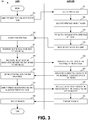
- Figure 3 illustrates a schematic view of a method 300 for managing data, e.g., using the system 100, in which the RFID tags 106, 108 may be provided to the user prior to the tag IDs thereof being associated with the machines 104 (and/or locations thereon) in the database 112.
- the method 300 may begin by the user requesting a number of RFID tags 106, 108, as at 302.
- the number of RFID tags 106, 108 may be requested, for example, as part of a standardized lot or kit including a preselected number of tags, e.g., 30 tags. In other cases, the number of tags may be defined at the discretion of the user.
- the supplier may receive the request, as at 304, and allocate the number of RFID tags 106, 108, as at 306.
- the RFID tags 106, 108 may each be associated with a tag ID, and may be configured to transmit the tag ID to a tag reader, such as the tag reader included in the mobile data collector 102.
- the tag ID may thus be employed to populate the database 112, e.g., with indices for each of the tag IDs, as at 308.
- the tag IDs may be printed on labels fixed to or otherwise visibly indicted on or proximal to the RFID tags 106, 108.
- the RFID tags 106, 108 may not bear any visible indication of the tag ID. In either case and/or others, the RFID tags 106, 108 may be provided to the user, as at 310.
- the user may receive the RFID tags 106, 108, as at 312.
- the user may then attach one or more of the RFID tags 106, 108 to a desired location on or near the machines 104, as at 314.
- the user may then transmit data indicative of an association between the tag IDs of the RFID tags 106, 108 and the machine 104, e.g., including a location on the machines 104 where the RFID tags 106, 108 are positioned.
- Determining and sending the association of the tag IDs and machines 104 may be conducted in one or more of several ways.
- blank labels may be sent to a user along with the RFID tags 106, 108 at 310.
- the user may then access a program to name machines/locations.
- the tag numbers of one of the RFID tags 106, 108 may then be logged and associated with the machine/location named on the label in the database 112, and the label affixed to the RFID tag (e.g., RFID tag 106). Subsequently, the RFID tag 106 may be attached to the location indicated on the label attached thereto.
- the RFID tags 106, 108 may be fixed to a desired machine 104 and/or location.
- the image capture device of the mobile data collector 102 may then be employed to photograph the RFID tag (e.g., the RFID tag 106) and machine identifying information (e.g., as provided on a nameplate) of the machine 104.
- the machine identifying information and/or the tag ID may then be extracted from the captured image and associated together in the database 112.
- the photograph may be time stamped, e.g., as part of a route of several machines 104 with RFID tags 106, 108 considered in a particular order.
- the timestamp may be used to later establish a chronology, from which the machine 104 and/or location association may be determined.
- the mobile data collector 102 may capture an audio recording, e.g., of a user's voice speaking the machine/location identifying information and the tag ID.
- the mobile data collector 102 may be used to read the tag ID from the RFID tag, rather than or in addition using visual or audio cues for the tag ID.
- the tag IDs may be associated with the machines 104 and/or locations thereon on an ad hoc basis.
- the method 300 may proceed to the supplier associating the tag IDs with the appropriate machine identifying data in the database 112, as at 318. As with the method 200, the method 300 may then proceed to the supplier determining the operating envelope, as at 320. Further, the user may then collect the operating data, including appropriate measurement(s) of operating conditions, as at 322. The operating data collected may then be submitted back to the supplier (i.e., to the host computing device 110), as at 324, in association with the appropriate tag ID, where the data collected may be analyzed, as at 326. The results of the analyses may then be transmitted at 328 and received at 330, e.g., using a graphical user interface, or any other type of interface, telephone, written communication, etc.
- FIG. 4 illustrates a schematic view of a computing or processor system 400, according to an embodiment.
- the processor system 400 may be embodied by hardware and/or software included in the mobile data collector 102, the host computing device 110, the user computing device 120, and/or the mobile computing device 116, where included, and thus may operate to implement one or more aspects of the method(s) 100 and/or 200. Further, it will be appreciated that in various embodiments, any of the aforementioned elements of the system 100 may include multiple processor systems 400.
- the processor system 400 may include one or more processors 402 of varying core configurations (including multiple cores) and clock frequencies. The one or more processors 402 may be operable to execute instructions, apply logic, etc. It may be appreciated that these functions may be provided by multiple processors or multiple cores on a single chip operating in parallel and/or communicably linked together.
- the processor system 400 may also include a memory system, which may be or include one or more memory devices and/or computer-readable media 404 of varying physical dimensions, accessibility, storage capacities, etc. such as flash drives, hard drives, disks, random access memory, etc., for storing data, such as images, files, and program instructions for execution by the processor 402.
- the computer-readable media 404 may store instructions that, when executed by the processor 402, are configured to cause the processor system 400 to perform operations. For example, execution of such instructions may cause the processor system 400 to implement one or more portions and/or embodiments of the method(s) 200, 300 described above.
- the processor system 400 may also include one or more network interfaces 406.
- the network interfaces 406 may include any hardware, applications, and/or other software. Accordingly, the network interfaces 406 may include Ethernet adapters, wireless transceivers, PCI interfaces, and/or serial network components, for communicating over wired or wireless media using protocols, such as Ethernet, wireless Ethernet, etc.
- the processor system 400 may further include one or more peripheral interfaces 408, for communication with the display(s), the input devices, etc.
- the peripheral interface 408 may also communicate with any projectors, keyboards, mice, touchpads, sensors, other types of input and/or output peripherals, and/or the like.
- the components of processor system 400 need not be enclosed within a single enclosure or even located in close proximity to one another, but in other implementations, the components and/or others may be provided in a single enclosure.
- the memory device 404 may be physically or logically arranged or configured to store data on one or more storage devices 410.
- the storage device 410 may include one or more file systems or databases, such as the database 112 in any suitable format.
- the storage device 410 may also include one or more software programs 412, which may contain interpretable or executable instructions for performing one or more of the disclosed processes. When requested by the processor 402, one or more of the software programs 412, or a portion thereof, may be loaded from the storage devices 410 to the memory devices 404 for execution by the processor 402.
- processor system 400 may include any type of hardware components, including any necessary accompanying firmware or software, for performing the disclosed implementations.
- the processor system 400 may also be implemented in part or in whole by electronic circuit components or processors, such as application-specific integrated circuits (ASICs) or field-programmable gate arrays (FPGAs).
- ASICs application-specific integrated circuits
- FPGAs field-programmable gate arrays
- processor system 400 may be used to execute programs according to instructions received from another program or from another processor system altogether.
- commands may be received, executed, and their output returned entirely within the processing and/or memory of the processor system 400. Accordingly, neither a visual interface command terminal nor any terminal at all is strictly necessary for performing the described embodiments.
- first and second features are formed in direct contact
- additional features may be formed interposing the first and second features, such that the first and second features may not be in direct contact.
Landscapes
- Engineering & Computer Science (AREA)
- Physics & Mathematics (AREA)
- General Physics & Mathematics (AREA)
- Toxicology (AREA)
- Health & Medical Sciences (AREA)
- General Engineering & Computer Science (AREA)
- Automation & Control Theory (AREA)
- Quality & Reliability (AREA)
- Manufacturing & Machinery (AREA)
- Artificial Intelligence (AREA)
- Theoretical Computer Science (AREA)
- Computer Vision & Pattern Recognition (AREA)
- General Health & Medical Sciences (AREA)
- Electromagnetism (AREA)
- Arrangements For Transmission Of Measured Signals (AREA)
Claims (8)
- Système (100) de gestion de données, comprenant :une pluralité d'étiquettes d'identification radiofréquence (RFID) (106, 108) fixées à une pluralité de machines (104), chacune de la pluralité d'étiquettes RFID stockant une ID d'étiquette ;un collecteur de données mobile (102) configuré pour prendre une mesure d'une ou de plusieurs conditions de fonctionnement de la pluralité de machines et pour lire l'ID d'étiquette depuis une étiquette RFID proximale de la pluralité d'étiquettes RFID ; etun dispositif informatique (110, 116) comprenant un processeur et une mémoire stockant une base de données, la base de données associant l'ID d'étiquette de chacune de la pluralité d'étiquettes RFID à ladite une de la pluralité de machines à laquelle elle est fixée, le dispositif informatique étant configuré pour recevoir la mesure et l'ID d'étiquette depuis le collecteur de données mobile et analyser les une ou plusieurs conditions de fonctionnement,caractérisé en ce que le collecteur de données mobile est équipé d'un ou de plusieurs capteurs ; etle collecteur de données mobile (102) est configuré en outre pour déterminer automatiquement lorsque le collecteur de données mobile est à proximité d'une étiquette RFID et démarrer automatiquement la prise d'une ou de plusieurs mesures de conditions de fonctionnement.
- Système selon la revendication 1, dans lequel le collecteur de données mobile (102) est configuré en outre pour détecter lorsqu'une condition en cours de mesure a atteint un état stable dans le collecteur de données mobile et pour prendre une mesure de la condition à l'état stable.
- Système selon la revendication 1, dans lequel le dispositif informatique (110, 116) est configuré pour transmettre un résultat de l'analyse au collecteur de données mobile.
- Système selon la revendication 1, dans lequel le collecteur de données mobile (102) comprend un dispositif de capture d'image et/ou un dispositif de capture audio, et dans lequel le collecteur de données mobile est configuré pour capturer une image et/ou un enregistrement audio indiquant une identité de l'une de la pluralité de machines et l'ID d'étiquette de l'une de la pluralité d'étiquettes RFID.
- Système selon la revendication 4, dans lequel le collecteur de données mobile (102) est configuré pour extraire de l'image et/ou de l'enregistrement audio l'identité de ladite une de la pluralité de machines et l'ID d'étiquette, et transmettre l'identité et l'ID d'étiquette au dispositif informatique.
- Système selon la revendication 4, dans lequel le collecteur de données mobile (102) est configuré pour transmettre l'image et/ou l'enregistrement audio au dispositif informations en vue de leur extraction.
- Système selon la revendication 1, dans lequel la pluralité d'étiquettes RFID (106, 108) sont positionnées à des emplacements sur la pluralité de machines, dans lequel l'ID d'étiquette de chacune des étiquettes RFID est associée à l'emplacement auquel l'étiquette RFID respective est fixée, et dans lequel au moins une de la pluralité de machines possède au moins deux étiquettes RFID qui y sont fixées à des emplacements différents.
- Système selon la revendication 7, dans lequel le collecteur de données mobile (102) est configuré pour capturer l'ID d'étiquette de l'une de la pluralité d'étiquettes RFID lorsque le collecteur de données mobile est positionné à proximité d'un emplacement auquel ladite une de la pluralité d'étiquettes RFID est fixée, et dans lequel l'ID d'étiquette est stockée en association avec l'emplacement.
Applications Claiming Priority (2)
| Application Number | Priority Date | Filing Date | Title |
|---|---|---|---|
| US201261737290P | 2012-12-14 | 2012-12-14 | |
| PCT/US2013/075283 WO2014093963A1 (fr) | 2012-12-14 | 2013-12-16 | Système et procédé de collecte de données portables |
Publications (3)
| Publication Number | Publication Date |
|---|---|
| EP2932485A1 EP2932485A1 (fr) | 2015-10-21 |
| EP2932485A4 EP2932485A4 (fr) | 2016-09-21 |
| EP2932485B1 true EP2932485B1 (fr) | 2019-09-18 |
Family
ID=50935025
Family Applications (1)
| Application Number | Title | Priority Date | Filing Date |
|---|---|---|---|
| EP13863062.9A Active EP2932485B1 (fr) | 2012-12-14 | 2013-12-16 | Système et procédé de collecte de données portables |
Country Status (5)
| Country | Link |
|---|---|
| US (1) | US9773135B2 (fr) |
| EP (1) | EP2932485B1 (fr) |
| CN (1) | CN105164736B (fr) |
| BR (1) | BR112015013946A2 (fr) |
| WO (1) | WO2014093963A1 (fr) |
Families Citing this family (13)
| Publication number | Priority date | Publication date | Assignee | Title |
|---|---|---|---|---|
| US9171192B2 (en) * | 2013-04-29 | 2015-10-27 | Aktiebolaget Skf | One touch data collection method and medium |
| FR3041419B1 (fr) * | 2015-09-21 | 2017-11-24 | Seb Sa | Procede d’identification d’un filtre et appareil domestique de traitement de l’air associe |
| DE102016100691A1 (de) * | 2016-01-18 | 2017-07-20 | Sick Ag | System und Verfahren mit einem System |
| JP6412055B2 (ja) * | 2016-05-18 | 2018-10-24 | ファナック株式会社 | 射出成形機管理システム |
| CN107066457B (zh) * | 2016-08-23 | 2019-12-17 | 平安科技(深圳)有限公司 | 用户信息视图构建方法和系统 |
| DE202016105595U1 (de) * | 2016-10-07 | 2018-01-09 | Sick Ag | Sicherheitssystem mit einem Sicherheitsschalter |
| DE112018000705T5 (de) | 2017-03-06 | 2019-11-14 | Cummins Filtration Ip, Inc. | Erkennung von echten filtern mit einem filterüberwachungssystem |
| US10208589B2 (en) | 2017-06-16 | 2019-02-19 | Forum Us, Inc. | Methods and systems for tracking drilling equipment |
| US10794150B2 (en) | 2017-06-16 | 2020-10-06 | Forum Us, Inc. | Predicting and optimizing drilling equipment operating life using condition based maintenance |
| US10591908B2 (en) | 2017-06-16 | 2020-03-17 | Forum Us, Inc. | Rig or wellsite safety intervention |
| CN110866612A (zh) * | 2018-08-10 | 2020-03-06 | 奥的斯电梯公司 | 使用识别标签创建用于维护记录的区块链 |
| CN110858329A (zh) * | 2018-08-10 | 2020-03-03 | 奥的斯电梯公司 | 创建用于维护记录的区块链 |
| WO2021030175A1 (fr) | 2019-08-09 | 2021-02-18 | Particle Measuring Systems, Inc | Systèmes à restriction d'accès utilisateur et procédés pour faire fonctionner des dispositifs d'échantillonnage de particules |
Family Cites Families (8)
| Publication number | Priority date | Publication date | Assignee | Title |
|---|---|---|---|---|
| US7503478B2 (en) * | 2000-05-01 | 2009-03-17 | Jeffery R Clark | Light fixture management system |
| US7142114B2 (en) * | 2003-09-30 | 2006-11-28 | General Electric Company | Non-contact patient temperature measurement |
| US7142107B2 (en) * | 2004-05-27 | 2006-11-28 | Lawrence Kates | Wireless sensor unit |
| US7400054B2 (en) * | 2006-01-10 | 2008-07-15 | General Electric Company | Method and assembly for detecting blade status in a wind turbine |
| US8212655B2 (en) * | 2006-03-30 | 2012-07-03 | Rosemount Inc. | System and method for identification of process components |
| US20080201388A1 (en) * | 2007-02-20 | 2008-08-21 | Luke Wood | System and method for equipment tracking and preventative maintenance scheduling and verification |
| US20110279245A1 (en) * | 2010-05-13 | 2011-11-17 | Advanced Manufacturing Control Systems Ltd. | System and method for associating rfid smart labels with customer database records for use with automated tracking of waste and recyclable material |
| CN102700797A (zh) * | 2012-06-05 | 2012-10-03 | 深圳市神拓机电设备有限公司 | 轴承座密封储料箱 |
-
2013
- 2013-12-16 EP EP13863062.9A patent/EP2932485B1/fr active Active
- 2013-12-16 BR BR112015013946A patent/BR112015013946A2/pt not_active IP Right Cessation
- 2013-12-16 CN CN201380070564.6A patent/CN105164736B/zh active Active
- 2013-12-16 WO PCT/US2013/075283 patent/WO2014093963A1/fr not_active Ceased
- 2013-12-16 US US14/652,265 patent/US9773135B2/en active Active
Non-Patent Citations (1)
| Title |
|---|
| None * |
Also Published As
| Publication number | Publication date |
|---|---|
| US20150332073A1 (en) | 2015-11-19 |
| US9773135B2 (en) | 2017-09-26 |
| EP2932485A1 (fr) | 2015-10-21 |
| CN105164736B (zh) | 2018-01-12 |
| BR112015013946A2 (pt) | 2017-07-11 |
| WO2014093963A1 (fr) | 2014-06-19 |
| CN105164736A (zh) | 2015-12-16 |
| EP2932485A4 (fr) | 2016-09-21 |
Similar Documents
| Publication | Publication Date | Title |
|---|---|---|
| EP2932485B1 (fr) | Système et procédé de collecte de données portables | |
| US10915204B2 (en) | Systems and methods for identifying faulty touch panel having intermittent field failures | |
| US10317474B2 (en) | Systems and methods for identifying faulty battery in an electronic device | |
| US9886338B1 (en) | Health check solution evaluating system status | |
| EP3441836B1 (fr) | Algorithme et procédé pour détecter des défauts d'une machine sur la base d'une technique d'apprentissage automatique | |
| JP6546907B2 (ja) | 機器用統合データ収集及び報告インタフェース | |
| US20180120265A1 (en) | Automatic mechanical systems diagnosis | |
| EP2686771B1 (fr) | Essai de facilité d'emploi | |
| JP6112220B2 (ja) | トレースデータ記録システム、トレースデータ記録サーバ、トレースデータ記録方法、プログラム、及び情報記憶媒体 | |
| CN115038937B (zh) | 运行状况监测系统 | |
| CN108920337A (zh) | 一种设备异常信息展示方法和计算机设备 | |
| WO2017058948A1 (fr) | Système et procédés de mise en service et de maintenance d'un équipement industriel | |
| CN103336256B (zh) | Wat探针卡智能处理系统及方法 | |
| CN113570009A (zh) | 电力设备出入库识别系统、方法、装置和计算机设备 | |
| EP2992518B1 (fr) | Procédé de collecte de données en un seul contact et support | |
| US8973815B2 (en) | One touch data collection apparatus | |
| CN111935247B (zh) | 一种基于物联网的实验设备管理系统及其使用方法 | |
| CN112019600A (zh) | 一种基于教学器材的信息数据点检处理系统及方法 | |
| TW202127159A (zh) | 用於控制可變物理參數的功能裝置及方法 | |
| TR201813425U5 (tr) | Bi̇r lazer epi̇lasyon ci̇hazi |
Legal Events
| Date | Code | Title | Description |
|---|---|---|---|
| PUAI | Public reference made under article 153(3) epc to a published international application that has entered the european phase |
Free format text: ORIGINAL CODE: 0009012 |
|
| 17P | Request for examination filed |
Effective date: 20150615 |
|
| AK | Designated contracting states |
Kind code of ref document: A1 Designated state(s): AL AT BE BG CH CY CZ DE DK EE ES FI FR GB GR HR HU IE IS IT LI LT LU LV MC MK MT NL NO PL PT RO RS SE SI SK SM TR |
|
| AX | Request for extension of the european patent |
Extension state: BA ME |
|
| DAX | Request for extension of the european patent (deleted) | ||
| REG | Reference to a national code |
Ref country code: DE Ref legal event code: R079 Ref document number: 602013060805 Country of ref document: DE Free format text: PREVIOUS MAIN CLASS: G08B0013140000 Ipc: G05B0019418000 |
|
| A4 | Supplementary search report drawn up and despatched |
Effective date: 20160819 |
|
| RIC1 | Information provided on ipc code assigned before grant |
Ipc: G08B 13/14 20060101ALI20160815BHEP Ipc: G05B 19/418 20060101AFI20160815BHEP |
|
| GRAP | Despatch of communication of intention to grant a patent |
Free format text: ORIGINAL CODE: EPIDOSNIGR1 |
|
| STAA | Information on the status of an ep patent application or granted ep patent |
Free format text: STATUS: GRANT OF PATENT IS INTENDED |
|
| INTG | Intention to grant announced |
Effective date: 20190416 |
|
| RIN1 | Information on inventor provided before grant (corrected) |
Inventor name: MURPHY, JONATHAN D. |
|
| GRAS | Grant fee paid |
Free format text: ORIGINAL CODE: EPIDOSNIGR3 |
|
| GRAA | (expected) grant |
Free format text: ORIGINAL CODE: 0009210 |
|
| STAA | Information on the status of an ep patent application or granted ep patent |
Free format text: STATUS: THE PATENT HAS BEEN GRANTED |
|
| AK | Designated contracting states |
Kind code of ref document: B1 Designated state(s): AL AT BE BG CH CY CZ DE DK EE ES FI FR GB GR HR HU IE IS IT LI LT LU LV MC MK MT NL NO PL PT RO RS SE SI SK SM TR |
|
| REG | Reference to a national code |
Ref country code: GB Ref legal event code: FG4D |
|
| REG | Reference to a national code |
Ref country code: CH Ref legal event code: EP |
|
| REG | Reference to a national code |
Ref country code: DE Ref legal event code: R096 Ref document number: 602013060805 Country of ref document: DE |
|
| REG | Reference to a national code |
Ref country code: AT Ref legal event code: REF Ref document number: 1182062 Country of ref document: AT Kind code of ref document: T Effective date: 20191015 |
|
| REG | Reference to a national code |
Ref country code: IE Ref legal event code: FG4D |
|
| REG | Reference to a national code |
Ref country code: NL Ref legal event code: MP Effective date: 20190918 |
|
| PG25 | Lapsed in a contracting state [announced via postgrant information from national office to epo] |
Ref country code: LT Free format text: LAPSE BECAUSE OF FAILURE TO SUBMIT A TRANSLATION OF THE DESCRIPTION OR TO PAY THE FEE WITHIN THE PRESCRIBED TIME-LIMIT Effective date: 20190918 Ref country code: HR Free format text: LAPSE BECAUSE OF FAILURE TO SUBMIT A TRANSLATION OF THE DESCRIPTION OR TO PAY THE FEE WITHIN THE PRESCRIBED TIME-LIMIT Effective date: 20190918 Ref country code: BG Free format text: LAPSE BECAUSE OF FAILURE TO SUBMIT A TRANSLATION OF THE DESCRIPTION OR TO PAY THE FEE WITHIN THE PRESCRIBED TIME-LIMIT Effective date: 20191218 Ref country code: SE Free format text: LAPSE BECAUSE OF FAILURE TO SUBMIT A TRANSLATION OF THE DESCRIPTION OR TO PAY THE FEE WITHIN THE PRESCRIBED TIME-LIMIT Effective date: 20190918 Ref country code: FI Free format text: LAPSE BECAUSE OF FAILURE TO SUBMIT A TRANSLATION OF THE DESCRIPTION OR TO PAY THE FEE WITHIN THE PRESCRIBED TIME-LIMIT Effective date: 20190918 Ref country code: NO Free format text: LAPSE BECAUSE OF FAILURE TO SUBMIT A TRANSLATION OF THE DESCRIPTION OR TO PAY THE FEE WITHIN THE PRESCRIBED TIME-LIMIT Effective date: 20191218 |
|
| REG | Reference to a national code |
Ref country code: LT Ref legal event code: MG4D |
|
| PG25 | Lapsed in a contracting state [announced via postgrant information from national office to epo] |
Ref country code: LV Free format text: LAPSE BECAUSE OF FAILURE TO SUBMIT A TRANSLATION OF THE DESCRIPTION OR TO PAY THE FEE WITHIN THE PRESCRIBED TIME-LIMIT Effective date: 20190918 Ref country code: RS Free format text: LAPSE BECAUSE OF FAILURE TO SUBMIT A TRANSLATION OF THE DESCRIPTION OR TO PAY THE FEE WITHIN THE PRESCRIBED TIME-LIMIT Effective date: 20190918 Ref country code: AL Free format text: LAPSE BECAUSE OF FAILURE TO SUBMIT A TRANSLATION OF THE DESCRIPTION OR TO PAY THE FEE WITHIN THE PRESCRIBED TIME-LIMIT Effective date: 20190918 Ref country code: GR Free format text: LAPSE BECAUSE OF FAILURE TO SUBMIT A TRANSLATION OF THE DESCRIPTION OR TO PAY THE FEE WITHIN THE PRESCRIBED TIME-LIMIT Effective date: 20191219 |
|
| REG | Reference to a national code |
Ref country code: AT Ref legal event code: MK05 Ref document number: 1182062 Country of ref document: AT Kind code of ref document: T Effective date: 20190918 |
|
| PG25 | Lapsed in a contracting state [announced via postgrant information from national office to epo] |
Ref country code: NL Free format text: LAPSE BECAUSE OF FAILURE TO SUBMIT A TRANSLATION OF THE DESCRIPTION OR TO PAY THE FEE WITHIN THE PRESCRIBED TIME-LIMIT Effective date: 20190918 Ref country code: ES Free format text: LAPSE BECAUSE OF FAILURE TO SUBMIT A TRANSLATION OF THE DESCRIPTION OR TO PAY THE FEE WITHIN THE PRESCRIBED TIME-LIMIT Effective date: 20190918 Ref country code: PT Free format text: LAPSE BECAUSE OF FAILURE TO SUBMIT A TRANSLATION OF THE DESCRIPTION OR TO PAY THE FEE WITHIN THE PRESCRIBED TIME-LIMIT Effective date: 20200120 Ref country code: PL Free format text: LAPSE BECAUSE OF FAILURE TO SUBMIT A TRANSLATION OF THE DESCRIPTION OR TO PAY THE FEE WITHIN THE PRESCRIBED TIME-LIMIT Effective date: 20190918 Ref country code: IT Free format text: LAPSE BECAUSE OF FAILURE TO SUBMIT A TRANSLATION OF THE DESCRIPTION OR TO PAY THE FEE WITHIN THE PRESCRIBED TIME-LIMIT Effective date: 20190918 Ref country code: RO Free format text: LAPSE BECAUSE OF FAILURE TO SUBMIT A TRANSLATION OF THE DESCRIPTION OR TO PAY THE FEE WITHIN THE PRESCRIBED TIME-LIMIT Effective date: 20190918 Ref country code: EE Free format text: LAPSE BECAUSE OF FAILURE TO SUBMIT A TRANSLATION OF THE DESCRIPTION OR TO PAY THE FEE WITHIN THE PRESCRIBED TIME-LIMIT Effective date: 20190918 Ref country code: AT Free format text: LAPSE BECAUSE OF FAILURE TO SUBMIT A TRANSLATION OF THE DESCRIPTION OR TO PAY THE FEE WITHIN THE PRESCRIBED TIME-LIMIT Effective date: 20190918 |
|
| PG25 | Lapsed in a contracting state [announced via postgrant information from national office to epo] |
Ref country code: SM Free format text: LAPSE BECAUSE OF FAILURE TO SUBMIT A TRANSLATION OF THE DESCRIPTION OR TO PAY THE FEE WITHIN THE PRESCRIBED TIME-LIMIT Effective date: 20190918 Ref country code: CZ Free format text: LAPSE BECAUSE OF FAILURE TO SUBMIT A TRANSLATION OF THE DESCRIPTION OR TO PAY THE FEE WITHIN THE PRESCRIBED TIME-LIMIT Effective date: 20190918 Ref country code: IS Free format text: LAPSE BECAUSE OF FAILURE TO SUBMIT A TRANSLATION OF THE DESCRIPTION OR TO PAY THE FEE WITHIN THE PRESCRIBED TIME-LIMIT Effective date: 20200224 Ref country code: SK Free format text: LAPSE BECAUSE OF FAILURE TO SUBMIT A TRANSLATION OF THE DESCRIPTION OR TO PAY THE FEE WITHIN THE PRESCRIBED TIME-LIMIT Effective date: 20190918 |
|
| REG | Reference to a national code |
Ref country code: DE Ref legal event code: R097 Ref document number: 602013060805 Country of ref document: DE |
|
| PLBE | No opposition filed within time limit |
Free format text: ORIGINAL CODE: 0009261 |
|
| STAA | Information on the status of an ep patent application or granted ep patent |
Free format text: STATUS: NO OPPOSITION FILED WITHIN TIME LIMIT |
|
| PG2D | Information on lapse in contracting state deleted |
Ref country code: IS |
|
| PG25 | Lapsed in a contracting state [announced via postgrant information from national office to epo] |
Ref country code: DK Free format text: LAPSE BECAUSE OF FAILURE TO SUBMIT A TRANSLATION OF THE DESCRIPTION OR TO PAY THE FEE WITHIN THE PRESCRIBED TIME-LIMIT Effective date: 20190918 Ref country code: IS Free format text: LAPSE BECAUSE OF FAILURE TO SUBMIT A TRANSLATION OF THE DESCRIPTION OR TO PAY THE FEE WITHIN THE PRESCRIBED TIME-LIMIT Effective date: 20200119 |
|
| REG | Reference to a national code |
Ref country code: CH Ref legal event code: PL |
|
| 26N | No opposition filed |
Effective date: 20200619 |
|
| REG | Reference to a national code |
Ref country code: BE Ref legal event code: MM Effective date: 20191231 |
|
| PG25 | Lapsed in a contracting state [announced via postgrant information from national office to epo] |
Ref country code: MC Free format text: LAPSE BECAUSE OF FAILURE TO SUBMIT A TRANSLATION OF THE DESCRIPTION OR TO PAY THE FEE WITHIN THE PRESCRIBED TIME-LIMIT Effective date: 20190918 Ref country code: SI Free format text: LAPSE BECAUSE OF FAILURE TO SUBMIT A TRANSLATION OF THE DESCRIPTION OR TO PAY THE FEE WITHIN THE PRESCRIBED TIME-LIMIT Effective date: 20190918 |
|
| GBPC | Gb: european patent ceased through non-payment of renewal fee |
Effective date: 20191218 |
|
| PG25 | Lapsed in a contracting state [announced via postgrant information from national office to epo] |
Ref country code: FR Free format text: LAPSE BECAUSE OF NON-PAYMENT OF DUE FEES Effective date: 20191231 Ref country code: LU Free format text: LAPSE BECAUSE OF NON-PAYMENT OF DUE FEES Effective date: 20191216 Ref country code: GB Free format text: LAPSE BECAUSE OF NON-PAYMENT OF DUE FEES Effective date: 20191218 Ref country code: IE Free format text: LAPSE BECAUSE OF NON-PAYMENT OF DUE FEES Effective date: 20191216 |
|
| PG25 | Lapsed in a contracting state [announced via postgrant information from national office to epo] |
Ref country code: LI Free format text: LAPSE BECAUSE OF NON-PAYMENT OF DUE FEES Effective date: 20191231 Ref country code: CH Free format text: LAPSE BECAUSE OF NON-PAYMENT OF DUE FEES Effective date: 20191231 Ref country code: BE Free format text: LAPSE BECAUSE OF NON-PAYMENT OF DUE FEES Effective date: 20191231 |
|
| PG25 | Lapsed in a contracting state [announced via postgrant information from national office to epo] |
Ref country code: CY Free format text: LAPSE BECAUSE OF FAILURE TO SUBMIT A TRANSLATION OF THE DESCRIPTION OR TO PAY THE FEE WITHIN THE PRESCRIBED TIME-LIMIT Effective date: 20190918 |
|
| PG25 | Lapsed in a contracting state [announced via postgrant information from national office to epo] |
Ref country code: MT Free format text: LAPSE BECAUSE OF FAILURE TO SUBMIT A TRANSLATION OF THE DESCRIPTION OR TO PAY THE FEE WITHIN THE PRESCRIBED TIME-LIMIT Effective date: 20190918 Ref country code: HU Free format text: LAPSE BECAUSE OF FAILURE TO SUBMIT A TRANSLATION OF THE DESCRIPTION OR TO PAY THE FEE WITHIN THE PRESCRIBED TIME-LIMIT; INVALID AB INITIO Effective date: 20131216 |
|
| PG25 | Lapsed in a contracting state [announced via postgrant information from national office to epo] |
Ref country code: TR Free format text: LAPSE BECAUSE OF FAILURE TO SUBMIT A TRANSLATION OF THE DESCRIPTION OR TO PAY THE FEE WITHIN THE PRESCRIBED TIME-LIMIT Effective date: 20190918 |
|
| PG25 | Lapsed in a contracting state [announced via postgrant information from national office to epo] |
Ref country code: MK Free format text: LAPSE BECAUSE OF FAILURE TO SUBMIT A TRANSLATION OF THE DESCRIPTION OR TO PAY THE FEE WITHIN THE PRESCRIBED TIME-LIMIT Effective date: 20190918 |
|
| P01 | Opt-out of the competence of the unified patent court (upc) registered |
Effective date: 20230513 |
|
| PGFP | Annual fee paid to national office [announced via postgrant information from national office to epo] |
Ref country code: DE Payment date: 20251229 Year of fee payment: 13 |