EP2932576B1 - Schnelles aufladesystem für elektrofahrzeuge - Google Patents
Schnelles aufladesystem für elektrofahrzeuge Download PDFInfo
- Publication number
- EP2932576B1 EP2932576B1 EP13863124.7A EP13863124A EP2932576B1 EP 2932576 B1 EP2932576 B1 EP 2932576B1 EP 13863124 A EP13863124 A EP 13863124A EP 2932576 B1 EP2932576 B1 EP 2932576B1
- Authority
- EP
- European Patent Office
- Prior art keywords
- component
- electric vehicle
- fuel
- natural gas
- gas
- Prior art date
- Legal status (The legal status is an assumption and is not a legal conclusion. Google has not performed a legal analysis and makes no representation as to the accuracy of the status listed.)
- Active
Links
Images



Classifications
-
- B—PERFORMING OPERATIONS; TRANSPORTING
- B60—VEHICLES IN GENERAL
- B60L—PROPULSION OF ELECTRICALLY-PROPELLED VEHICLES; SUPPLYING ELECTRIC POWER FOR AUXILIARY EQUIPMENT OF ELECTRICALLY-PROPELLED VEHICLES; ELECTRODYNAMIC BRAKE SYSTEMS FOR VEHICLES IN GENERAL; MAGNETIC SUSPENSION OR LEVITATION FOR VEHICLES; MONITORING OPERATING VARIABLES OF ELECTRICALLY-PROPELLED VEHICLES; ELECTRIC SAFETY DEVICES FOR ELECTRICALLY-PROPELLED VEHICLES
- B60L50/00—Electric propulsion with power supplied within the vehicle
- B60L50/50—Electric propulsion with power supplied within the vehicle using propulsion power supplied by batteries or fuel cells
- B60L50/60—Electric propulsion with power supplied within the vehicle using propulsion power supplied by batteries or fuel cells using power supplied by batteries
- B60L50/66—Arrangements of batteries
-
- B—PERFORMING OPERATIONS; TRANSPORTING
- B60—VEHICLES IN GENERAL
- B60L—PROPULSION OF ELECTRICALLY-PROPELLED VEHICLES; SUPPLYING ELECTRIC POWER FOR AUXILIARY EQUIPMENT OF ELECTRICALLY-PROPELLED VEHICLES; ELECTRODYNAMIC BRAKE SYSTEMS FOR VEHICLES IN GENERAL; MAGNETIC SUSPENSION OR LEVITATION FOR VEHICLES; MONITORING OPERATING VARIABLES OF ELECTRICALLY-PROPELLED VEHICLES; ELECTRIC SAFETY DEVICES FOR ELECTRICALLY-PROPELLED VEHICLES
- B60L53/00—Methods of charging batteries, specially adapted for electric vehicles; Charging stations or on-board charging equipment therefor; Exchange of energy storage elements in electric vehicles
- B60L53/10—Methods of charging batteries, specially adapted for electric vehicles; Charging stations or on-board charging equipment therefor; Exchange of energy storage elements in electric vehicles characterised by the energy transfer between the charging station and the vehicle
- B60L53/11—DC charging controlled by the charging station, e.g. mode 4
-
- B—PERFORMING OPERATIONS; TRANSPORTING
- B60—VEHICLES IN GENERAL
- B60L—PROPULSION OF ELECTRICALLY-PROPELLED VEHICLES; SUPPLYING ELECTRIC POWER FOR AUXILIARY EQUIPMENT OF ELECTRICALLY-PROPELLED VEHICLES; ELECTRODYNAMIC BRAKE SYSTEMS FOR VEHICLES IN GENERAL; MAGNETIC SUSPENSION OR LEVITATION FOR VEHICLES; MONITORING OPERATING VARIABLES OF ELECTRICALLY-PROPELLED VEHICLES; ELECTRIC SAFETY DEVICES FOR ELECTRICALLY-PROPELLED VEHICLES
- B60L53/00—Methods of charging batteries, specially adapted for electric vehicles; Charging stations or on-board charging equipment therefor; Exchange of energy storage elements in electric vehicles
- B60L53/30—Constructional details of charging stations
-
- B—PERFORMING OPERATIONS; TRANSPORTING
- B60—VEHICLES IN GENERAL
- B60L—PROPULSION OF ELECTRICALLY-PROPELLED VEHICLES; SUPPLYING ELECTRIC POWER FOR AUXILIARY EQUIPMENT OF ELECTRICALLY-PROPELLED VEHICLES; ELECTRODYNAMIC BRAKE SYSTEMS FOR VEHICLES IN GENERAL; MAGNETIC SUSPENSION OR LEVITATION FOR VEHICLES; MONITORING OPERATING VARIABLES OF ELECTRICALLY-PROPELLED VEHICLES; ELECTRIC SAFETY DEVICES FOR ELECTRICALLY-PROPELLED VEHICLES
- B60L53/00—Methods of charging batteries, specially adapted for electric vehicles; Charging stations or on-board charging equipment therefor; Exchange of energy storage elements in electric vehicles
- B60L53/30—Constructional details of charging stations
- B60L53/31—Charging columns specially adapted for electric vehicles
-
- B—PERFORMING OPERATIONS; TRANSPORTING
- B60—VEHICLES IN GENERAL
- B60L—PROPULSION OF ELECTRICALLY-PROPELLED VEHICLES; SUPPLYING ELECTRIC POWER FOR AUXILIARY EQUIPMENT OF ELECTRICALLY-PROPELLED VEHICLES; ELECTRODYNAMIC BRAKE SYSTEMS FOR VEHICLES IN GENERAL; MAGNETIC SUSPENSION OR LEVITATION FOR VEHICLES; MONITORING OPERATING VARIABLES OF ELECTRICALLY-PROPELLED VEHICLES; ELECTRIC SAFETY DEVICES FOR ELECTRICALLY-PROPELLED VEHICLES
- B60L53/00—Methods of charging batteries, specially adapted for electric vehicles; Charging stations or on-board charging equipment therefor; Exchange of energy storage elements in electric vehicles
- B60L53/50—Charging stations characterised by energy-storage or power-generation means
-
- B—PERFORMING OPERATIONS; TRANSPORTING
- B60—VEHICLES IN GENERAL
- B60L—PROPULSION OF ELECTRICALLY-PROPELLED VEHICLES; SUPPLYING ELECTRIC POWER FOR AUXILIARY EQUIPMENT OF ELECTRICALLY-PROPELLED VEHICLES; ELECTRODYNAMIC BRAKE SYSTEMS FOR VEHICLES IN GENERAL; MAGNETIC SUSPENSION OR LEVITATION FOR VEHICLES; MONITORING OPERATING VARIABLES OF ELECTRICALLY-PROPELLED VEHICLES; ELECTRIC SAFETY DEVICES FOR ELECTRICALLY-PROPELLED VEHICLES
- B60L53/00—Methods of charging batteries, specially adapted for electric vehicles; Charging stations or on-board charging equipment therefor; Exchange of energy storage elements in electric vehicles
- B60L53/50—Charging stations characterised by energy-storage or power-generation means
- B60L53/54—Fuel cells
-
- B—PERFORMING OPERATIONS; TRANSPORTING
- B60—VEHICLES IN GENERAL
- B60L—PROPULSION OF ELECTRICALLY-PROPELLED VEHICLES; SUPPLYING ELECTRIC POWER FOR AUXILIARY EQUIPMENT OF ELECTRICALLY-PROPELLED VEHICLES; ELECTRODYNAMIC BRAKE SYSTEMS FOR VEHICLES IN GENERAL; MAGNETIC SUSPENSION OR LEVITATION FOR VEHICLES; MONITORING OPERATING VARIABLES OF ELECTRICALLY-PROPELLED VEHICLES; ELECTRIC SAFETY DEVICES FOR ELECTRICALLY-PROPELLED VEHICLES
- B60L53/00—Methods of charging batteries, specially adapted for electric vehicles; Charging stations or on-board charging equipment therefor; Exchange of energy storage elements in electric vehicles
- B60L53/60—Monitoring or controlling charging stations
- B60L53/62—Monitoring or controlling charging stations in response to charging parameters, e.g. current, voltage or electrical charge
-
- B—PERFORMING OPERATIONS; TRANSPORTING
- B60—VEHICLES IN GENERAL
- B60L—PROPULSION OF ELECTRICALLY-PROPELLED VEHICLES; SUPPLYING ELECTRIC POWER FOR AUXILIARY EQUIPMENT OF ELECTRICALLY-PROPELLED VEHICLES; ELECTRODYNAMIC BRAKE SYSTEMS FOR VEHICLES IN GENERAL; MAGNETIC SUSPENSION OR LEVITATION FOR VEHICLES; MONITORING OPERATING VARIABLES OF ELECTRICALLY-PROPELLED VEHICLES; ELECTRIC SAFETY DEVICES FOR ELECTRICALLY-PROPELLED VEHICLES
- B60L53/00—Methods of charging batteries, specially adapted for electric vehicles; Charging stations or on-board charging equipment therefor; Exchange of energy storage elements in electric vehicles
- B60L53/60—Monitoring or controlling charging stations
- B60L53/65—Monitoring or controlling charging stations involving identification of vehicles or their battery types
-
- B—PERFORMING OPERATIONS; TRANSPORTING
- B60—VEHICLES IN GENERAL
- B60L—PROPULSION OF ELECTRICALLY-PROPELLED VEHICLES; SUPPLYING ELECTRIC POWER FOR AUXILIARY EQUIPMENT OF ELECTRICALLY-PROPELLED VEHICLES; ELECTRODYNAMIC BRAKE SYSTEMS FOR VEHICLES IN GENERAL; MAGNETIC SUSPENSION OR LEVITATION FOR VEHICLES; MONITORING OPERATING VARIABLES OF ELECTRICALLY-PROPELLED VEHICLES; ELECTRIC SAFETY DEVICES FOR ELECTRICALLY-PROPELLED VEHICLES
- B60L53/00—Methods of charging batteries, specially adapted for electric vehicles; Charging stations or on-board charging equipment therefor; Exchange of energy storage elements in electric vehicles
- B60L53/60—Monitoring or controlling charging stations
- B60L53/66—Data transfer between charging stations and vehicles
- B60L53/665—Methods related to measuring, billing or payment
-
- B—PERFORMING OPERATIONS; TRANSPORTING
- B60—VEHICLES IN GENERAL
- B60L—PROPULSION OF ELECTRICALLY-PROPELLED VEHICLES; SUPPLYING ELECTRIC POWER FOR AUXILIARY EQUIPMENT OF ELECTRICALLY-PROPELLED VEHICLES; ELECTRODYNAMIC BRAKE SYSTEMS FOR VEHICLES IN GENERAL; MAGNETIC SUSPENSION OR LEVITATION FOR VEHICLES; MONITORING OPERATING VARIABLES OF ELECTRICALLY-PROPELLED VEHICLES; ELECTRIC SAFETY DEVICES FOR ELECTRICALLY-PROPELLED VEHICLES
- B60L58/00—Methods or circuit arrangements for monitoring or controlling batteries or fuel cells, specially adapted for electric vehicles
- B60L58/10—Methods or circuit arrangements for monitoring or controlling batteries or fuel cells, specially adapted for electric vehicles for monitoring or controlling batteries
- B60L58/12—Methods or circuit arrangements for monitoring or controlling batteries or fuel cells, specially adapted for electric vehicles for monitoring or controlling batteries responding to state of charge [SoC]
-
- H—ELECTRICITY
- H01—ELECTRIC ELEMENTS
- H01M—PROCESSES OR MEANS, e.g. BATTERIES, FOR THE DIRECT CONVERSION OF CHEMICAL ENERGY INTO ELECTRICAL ENERGY
- H01M8/00—Fuel cells; Manufacture thereof
- H01M8/04—Auxiliary arrangements, e.g. for control of pressure or for circulation of fluids
- H01M8/04007—Auxiliary arrangements, e.g. for control of pressure or for circulation of fluids related to heat exchange
- H01M8/04014—Heat exchange using gaseous fluids; Heat exchange by combustion of reactants
-
- H—ELECTRICITY
- H01—ELECTRIC ELEMENTS
- H01M—PROCESSES OR MEANS, e.g. BATTERIES, FOR THE DIRECT CONVERSION OF CHEMICAL ENERGY INTO ELECTRICAL ENERGY
- H01M8/00—Fuel cells; Manufacture thereof
- H01M8/04—Auxiliary arrangements, e.g. for control of pressure or for circulation of fluids
- H01M8/04082—Arrangements for control of reactant parameters, e.g. pressure or concentration
- H01M8/04089—Arrangements for control of reactant parameters, e.g. pressure or concentration of gaseous reactants
- H01M8/04111—Arrangements for control of reactant parameters, e.g. pressure or concentration of gaseous reactants using a compressor turbine assembly
-
- H—ELECTRICITY
- H01—ELECTRIC ELEMENTS
- H01M—PROCESSES OR MEANS, e.g. BATTERIES, FOR THE DIRECT CONVERSION OF CHEMICAL ENERGY INTO ELECTRICAL ENERGY
- H01M8/00—Fuel cells; Manufacture thereof
- H01M8/04—Auxiliary arrangements, e.g. for control of pressure or for circulation of fluids
- H01M8/04082—Arrangements for control of reactant parameters, e.g. pressure or concentration
- H01M8/04201—Reactant storage and supply, e.g. means for feeding, pipes
-
- H—ELECTRICITY
- H01—ELECTRIC ELEMENTS
- H01M—PROCESSES OR MEANS, e.g. BATTERIES, FOR THE DIRECT CONVERSION OF CHEMICAL ENERGY INTO ELECTRICAL ENERGY
- H01M8/00—Fuel cells; Manufacture thereof
- H01M8/04—Auxiliary arrangements, e.g. for control of pressure or for circulation of fluids
- H01M8/04298—Processes for controlling fuel cells or fuel cell systems
- H01M8/04313—Processes for controlling fuel cells or fuel cell systems characterised by the detection or assessment of variables; characterised by the detection or assessment of failure or abnormal function
- H01M8/04537—Electric variables
- H01M8/04604—Power, energy, capacity or load
- H01M8/04619—Power, energy, capacity or load of fuel cell stacks
-
- H—ELECTRICITY
- H01—ELECTRIC ELEMENTS
- H01M—PROCESSES OR MEANS, e.g. BATTERIES, FOR THE DIRECT CONVERSION OF CHEMICAL ENERGY INTO ELECTRICAL ENERGY
- H01M8/00—Fuel cells; Manufacture thereof
- H01M8/04—Auxiliary arrangements, e.g. for control of pressure or for circulation of fluids
- H01M8/04298—Processes for controlling fuel cells or fuel cell systems
- H01M8/04694—Processes for controlling fuel cells or fuel cell systems characterised by variables to be controlled
- H01M8/04858—Electric variables
- H01M8/04925—Power, energy, capacity or load
- H01M8/0494—Power, energy, capacity or load of fuel cell stacks
-
- H—ELECTRICITY
- H01—ELECTRIC ELEMENTS
- H01M—PROCESSES OR MEANS, e.g. BATTERIES, FOR THE DIRECT CONVERSION OF CHEMICAL ENERGY INTO ELECTRICAL ENERGY
- H01M8/00—Fuel cells; Manufacture thereof
- H01M8/06—Combination of fuel cells with means for production of reactants or for treatment of residues
- H01M8/0606—Combination of fuel cells with means for production of reactants or for treatment of residues with means for production of gaseous reactants
-
- H—ELECTRICITY
- H01—ELECTRIC ELEMENTS
- H01M—PROCESSES OR MEANS, e.g. BATTERIES, FOR THE DIRECT CONVERSION OF CHEMICAL ENERGY INTO ELECTRICAL ENERGY
- H01M8/00—Fuel cells; Manufacture thereof
- H01M8/24—Grouping of fuel cells, e.g. stacking of fuel cells
- H01M8/249—Grouping of fuel cells, e.g. stacking of fuel cells comprising two or more groupings of fuel cells, e.g. modular assemblies
-
- B—PERFORMING OPERATIONS; TRANSPORTING
- B60—VEHICLES IN GENERAL
- B60L—PROPULSION OF ELECTRICALLY-PROPELLED VEHICLES; SUPPLYING ELECTRIC POWER FOR AUXILIARY EQUIPMENT OF ELECTRICALLY-PROPELLED VEHICLES; ELECTRODYNAMIC BRAKE SYSTEMS FOR VEHICLES IN GENERAL; MAGNETIC SUSPENSION OR LEVITATION FOR VEHICLES; MONITORING OPERATING VARIABLES OF ELECTRICALLY-PROPELLED VEHICLES; ELECTRIC SAFETY DEVICES FOR ELECTRICALLY-PROPELLED VEHICLES
- B60L2240/00—Control parameters of input or output; Target parameters
- B60L2240/60—Navigation input
- B60L2240/66—Ambient conditions
- B60L2240/662—Temperature
-
- H—ELECTRICITY
- H01—ELECTRIC ELEMENTS
- H01M—PROCESSES OR MEANS, e.g. BATTERIES, FOR THE DIRECT CONVERSION OF CHEMICAL ENERGY INTO ELECTRICAL ENERGY
- H01M8/00—Fuel cells; Manufacture thereof
- H01M8/10—Fuel cells with solid electrolytes
- H01M2008/1095—Fuel cells with polymeric electrolytes
-
- H—ELECTRICITY
- H01—ELECTRIC ELEMENTS
- H01M—PROCESSES OR MEANS, e.g. BATTERIES, FOR THE DIRECT CONVERSION OF CHEMICAL ENERGY INTO ELECTRICAL ENERGY
- H01M2250/00—Fuel cells for particular applications; Specific features of fuel cell system
- H01M2250/20—Fuel cells in motive systems, e.g. vehicle, ship, plane
-
- Y—GENERAL TAGGING OF NEW TECHNOLOGICAL DEVELOPMENTS; GENERAL TAGGING OF CROSS-SECTIONAL TECHNOLOGIES SPANNING OVER SEVERAL SECTIONS OF THE IPC; TECHNICAL SUBJECTS COVERED BY FORMER USPC CROSS-REFERENCE ART COLLECTIONS [XRACs] AND DIGESTS
- Y02—TECHNOLOGIES OR APPLICATIONS FOR MITIGATION OR ADAPTATION AGAINST CLIMATE CHANGE
- Y02T—CLIMATE CHANGE MITIGATION TECHNOLOGIES RELATED TO TRANSPORTATION
- Y02T10/00—Road transport of goods or passengers
- Y02T10/60—Other road transportation technologies with climate change mitigation effect
- Y02T10/70—Energy storage systems for electromobility, e.g. batteries
-
- Y—GENERAL TAGGING OF NEW TECHNOLOGICAL DEVELOPMENTS; GENERAL TAGGING OF CROSS-SECTIONAL TECHNOLOGIES SPANNING OVER SEVERAL SECTIONS OF THE IPC; TECHNICAL SUBJECTS COVERED BY FORMER USPC CROSS-REFERENCE ART COLLECTIONS [XRACs] AND DIGESTS
- Y02—TECHNOLOGIES OR APPLICATIONS FOR MITIGATION OR ADAPTATION AGAINST CLIMATE CHANGE
- Y02T—CLIMATE CHANGE MITIGATION TECHNOLOGIES RELATED TO TRANSPORTATION
- Y02T10/00—Road transport of goods or passengers
- Y02T10/60—Other road transportation technologies with climate change mitigation effect
- Y02T10/7072—Electromobility specific charging systems or methods for batteries, ultracapacitors, supercapacitors or double-layer capacitors
-
- Y—GENERAL TAGGING OF NEW TECHNOLOGICAL DEVELOPMENTS; GENERAL TAGGING OF CROSS-SECTIONAL TECHNOLOGIES SPANNING OVER SEVERAL SECTIONS OF THE IPC; TECHNICAL SUBJECTS COVERED BY FORMER USPC CROSS-REFERENCE ART COLLECTIONS [XRACs] AND DIGESTS
- Y02—TECHNOLOGIES OR APPLICATIONS FOR MITIGATION OR ADAPTATION AGAINST CLIMATE CHANGE
- Y02T—CLIMATE CHANGE MITIGATION TECHNOLOGIES RELATED TO TRANSPORTATION
- Y02T10/00—Road transport of goods or passengers
- Y02T10/60—Other road transportation technologies with climate change mitigation effect
- Y02T10/72—Electric energy management in electromobility
-
- Y—GENERAL TAGGING OF NEW TECHNOLOGICAL DEVELOPMENTS; GENERAL TAGGING OF CROSS-SECTIONAL TECHNOLOGIES SPANNING OVER SEVERAL SECTIONS OF THE IPC; TECHNICAL SUBJECTS COVERED BY FORMER USPC CROSS-REFERENCE ART COLLECTIONS [XRACs] AND DIGESTS
- Y02—TECHNOLOGIES OR APPLICATIONS FOR MITIGATION OR ADAPTATION AGAINST CLIMATE CHANGE
- Y02T—CLIMATE CHANGE MITIGATION TECHNOLOGIES RELATED TO TRANSPORTATION
- Y02T90/00—Enabling technologies or technologies with a potential or indirect contribution to GHG emissions mitigation
- Y02T90/10—Technologies relating to charging of electric vehicles
- Y02T90/12—Electric charging stations
-
- Y—GENERAL TAGGING OF NEW TECHNOLOGICAL DEVELOPMENTS; GENERAL TAGGING OF CROSS-SECTIONAL TECHNOLOGIES SPANNING OVER SEVERAL SECTIONS OF THE IPC; TECHNICAL SUBJECTS COVERED BY FORMER USPC CROSS-REFERENCE ART COLLECTIONS [XRACs] AND DIGESTS
- Y02—TECHNOLOGIES OR APPLICATIONS FOR MITIGATION OR ADAPTATION AGAINST CLIMATE CHANGE
- Y02T—CLIMATE CHANGE MITIGATION TECHNOLOGIES RELATED TO TRANSPORTATION
- Y02T90/00—Enabling technologies or technologies with a potential or indirect contribution to GHG emissions mitigation
- Y02T90/10—Technologies relating to charging of electric vehicles
- Y02T90/14—Plug-in electric vehicles
-
- Y—GENERAL TAGGING OF NEW TECHNOLOGICAL DEVELOPMENTS; GENERAL TAGGING OF CROSS-SECTIONAL TECHNOLOGIES SPANNING OVER SEVERAL SECTIONS OF THE IPC; TECHNICAL SUBJECTS COVERED BY FORMER USPC CROSS-REFERENCE ART COLLECTIONS [XRACs] AND DIGESTS
- Y02—TECHNOLOGIES OR APPLICATIONS FOR MITIGATION OR ADAPTATION AGAINST CLIMATE CHANGE
- Y02T—CLIMATE CHANGE MITIGATION TECHNOLOGIES RELATED TO TRANSPORTATION
- Y02T90/00—Enabling technologies or technologies with a potential or indirect contribution to GHG emissions mitigation
- Y02T90/10—Technologies relating to charging of electric vehicles
- Y02T90/16—Information or communication technologies improving the operation of electric vehicles
-
- Y—GENERAL TAGGING OF NEW TECHNOLOGICAL DEVELOPMENTS; GENERAL TAGGING OF CROSS-SECTIONAL TECHNOLOGIES SPANNING OVER SEVERAL SECTIONS OF THE IPC; TECHNICAL SUBJECTS COVERED BY FORMER USPC CROSS-REFERENCE ART COLLECTIONS [XRACs] AND DIGESTS
- Y02—TECHNOLOGIES OR APPLICATIONS FOR MITIGATION OR ADAPTATION AGAINST CLIMATE CHANGE
- Y02T—CLIMATE CHANGE MITIGATION TECHNOLOGIES RELATED TO TRANSPORTATION
- Y02T90/00—Enabling technologies or technologies with a potential or indirect contribution to GHG emissions mitigation
- Y02T90/10—Technologies relating to charging of electric vehicles
- Y02T90/16—Information or communication technologies improving the operation of electric vehicles
- Y02T90/167—Systems integrating technologies related to power network operation and communication or information technologies for supporting the interoperability of electric or hybrid vehicles, i.e. smartgrids as interface for battery charging of electric vehicles [EV] or hybrid vehicles [HEV]
-
- Y—GENERAL TAGGING OF NEW TECHNOLOGICAL DEVELOPMENTS; GENERAL TAGGING OF CROSS-SECTIONAL TECHNOLOGIES SPANNING OVER SEVERAL SECTIONS OF THE IPC; TECHNICAL SUBJECTS COVERED BY FORMER USPC CROSS-REFERENCE ART COLLECTIONS [XRACs] AND DIGESTS
- Y04—INFORMATION OR COMMUNICATION TECHNOLOGIES HAVING AN IMPACT ON OTHER TECHNOLOGY AREAS
- Y04S—SYSTEMS INTEGRATING TECHNOLOGIES RELATED TO POWER NETWORK OPERATION, COMMUNICATION OR INFORMATION TECHNOLOGIES FOR IMPROVING THE ELECTRICAL POWER GENERATION, TRANSMISSION, DISTRIBUTION, MANAGEMENT OR USAGE, i.e. SMART GRIDS
- Y04S30/00—Systems supporting specific end-user applications in the sector of transportation
- Y04S30/10—Systems supporting the interoperability of electric or hybrid vehicles
- Y04S30/14—Details associated with the interoperability, e.g. vehicle recognition, authentication, identification or billing
Definitions
- the embodiments described and claimed herein relate generally to systems, apparatus, and methods for simultaneously charging the batteries of multiple Electric Vehicles. More specifically, at least some of the embodiments described herein relate to systems, apparatus, and methods for charging Electric Vehicles independent from the electric grid, using Liquid Natural Gas (referred to herein as "LNG”) or Natural Gas (“NG”) as an energy source.
- LNG Liquid Natural Gas
- NG Natural Gas
- WO 2009/105448 A2 is directed to a fuel cell system suitable for charging an electric vehicle in which charge is delivered from the fuel cell system to the battery of an electric vehicle through the vehicle interface without use of a direct current to alternating current converter.
- US 2005/0287404 A1 is directed to a fuel cell system and method of removing impurities from a catalyst.
- the Fast Charging System provides a method for simultaneously charging the batteries of multiple electric vehicles, largely independent from the electric grid (the power that is used to charge the Electric Vehicle does not originate from the grid; however, certain components of the embodiments described and claimed herein may be powered by the grid), using LNG or NG as an energy source. It can efficiently provide DC charging power tailored to the requirements of the individual vehicles being charged. It is estimated that a vehicle with a battery capacity of 85 kWh can be fully charged in less than 10 minutes using the Fast Charging System.
- an electric vehicle charging facility comprising a power generation component for generating a DC electric power, the power generation component comprising a plurality of fuel cells including a stack of up to about ten individual polymer electrolyte membrane fuel cells which operate independently, a fuel component supplying a fuel to the power generation component, a charging component electrically connected to the power generation component for charging an electric vehicle using the DC electric power, the charging component comprising a first customer charging station, and a control system component, wherein the control system component comprises a processor, a data storage, and instructions stored in the data storage and executable by the processor to activate the plurality of fuel cells individually and sequentially to meet an energy demand of the charging component, and based on information regarding the amount of charge and the rate of charge sent by the first customer charging station, compute an amount of fuel needed, and adjust a mass flow rate of fuel from the fuel component to the power generation component.
- an electric vehicle charging facility includes a power generation component, a fuel component, a charging component and a control system component.
- the power generation component generates DC electric power and includes a plurality of fuel cells having a capacity of between approximately 400 kW and approximately 500 kW.
- the fuel component supplies natural gas to the power generation component.
- the charging component is electrically connected to the power generation component for charging an electric vehicle using the DC electric power and includes at least one customer charging station.
- the power generation component also includes a converter for converting at least a portion of the DC electric power to an AC electric power.
- the control system component comprises a processor, a data storage, and instructions stored in the data storage and executable by the processor to activate the plurality of fuel cells sequentially to meet an energy demand of the charging component.
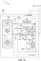
- the Fast Charge System 1 includes four main components, the Automated Control System Component 100, the Fuel Component 200, the Power Generation Component 300, and the Charging Component 400.
- the Automated Control System Component 100 controls the system.
- the Fuel Component 200 stores LNG and converts it, at a controlled and varying rate, into Natural Gas that will be used to produce DC Power to charge Electric Vehicles.
- the Fuel Component 200 can provide low pressure, piped NG instead of storing and converting LNG.
- the Power Generation Component 300 using the Natural Gas from the Fuel Component 200, produces, at a controlled and varying rate, DC Power 302 for the Charging Component 400 and Hot Water 502 that is used by the Fuel Component 200, and may optionally produce AC Power 304 that can be sold back to the grid or used for other purposes at the facility.
- the Charging Component 400 is the element used to dispense the DC Power 302 to the customer through separate Customer Charging Stations 410A, 410B (shown in Figure 1A -2) .
- the Automated Control System Component 100 controls the system.
- the customers will select the charging time, with the shorter the time the higher the price. More particularly, the customer inputs the time of charge and the amount of charge. For instance, the customer might select a charge time of 15 minutes and a total charge of 80% of the total capacity of the vehicle battery system. Alternatively, the customer can be presented with multiple charging options representing different charging times, different total charges, different rates of charge, and different prices, from which the customer can select.
- the connection plug from the vehicle to the charging station 410A, 410B will communicate the level of charge in the vehicle system before the charging begins as well as the vehicle battery system characteristics and capabilities.
- the Automated Control System 100 will register the customer payment information, the amount and rate of charge, and compute the volume of Natural Gas 273 required for the Power Generation Component 300 to generate the DC Power 302 required to charge all vehicles at the station and the amount of LNG necessary to produce that Natural Gas 273. More particularly, the Automated Control System 100 computes the amount of power required to charge the customer's battery in the time selected.
- the volume of Natural Gas 273 required is based upon the efficiency and productivity of the Fuel Cell(s) 310.
- the volume of LNG required is based upon the efficiency and productivity of the Liquid to Natural Gas Fast Transformer (referred to herein as "LNFT") 230.
- LNFT Liquid to Natural Gas Fast Transformer
- the Automated Control System 100 also controls and monitors other components in the system.
- the Automated Control System Component 100 also keeps track of LNG supply, provides an accounting and billing system and monitors the performance of various components.
- the Fast Charge System 1 can be monitored locally, remotely or both.
- the Fuel Component 200 stores LNG and converts it, at a controlled and varying rate, into Natural Gas 273 that will be used to produce DC Power 302 to charge Electric Vehicles.
- the Fuel Component 200 consists of three elements - the LNG Storage Tank 210, the LNFT 230, and the Gas Flow Buffering System 250.
- the LNG Storage Tank 210 is a standard LNG cryogenic double-wall container able to keep the LNG 214 at the needed temperature.
- the LNG Storage Tank 210 is a conventional or standard tank.
- LNG 214 is stored at approximately -260 degrees F. Although at that temperature, it exists at atmospheric pressure, LNG tanks are usually rated at 200 psig.
- the LNG 214 is usually stored at 40 psig.
- the size of the tank will depend upon the market at the location of the installation as well as the frequency of delivery of LNG 214 replacement. It is expected that in no case will the tank be larger than that with a capacity of about 3,000 gallons of LNG.
- the LNG Storage Tank 210 may include an internal submerged variable speed pump 212 to send LNG 214 to the LNFT 230.
- the size of the variable speed pump 212 will depend upon the number of charging stations 410A, 410B, the capacity of the LNFT 230 and the expected market. To charge an 85 kWh battery in approximately five minutes will require the simultaneous operation of one 500 kW fuel cell stack or five 100 kW fuel cell stacks. In either case, the fuel stack(s) will require approximately 1 ⁇ 2 gallon of LNG per minute worth of energy. If the service station installation had ten 100 kW fuel cell stacks, then the maximum flow rate from the variable speed pump would be 1 gallon per minute.
- the pressure rating required for the pump will be specific to the piping design at the individual site. As an option, the pump 212 can be external or included within the LNFT 230.
- the LNFT 230 produces the fuel (Natural Gas 243) needed for the Power Generation Component 300 by a fast and automated pressure and flow controlled transformation of the LNG 214 into Natural Gas 243.
- the pumped LNG 214 is received by the LNFT 230 and then boosted internally by a high-pressure pump 232 and sent to the Vaporizer 234.
- the size of the pump 232 will depend upon the specific piping pressure loss at the site as well as the specific pressure requirements of the Vaporizer 234.
- the heating of the boosted LNG 233 in the Vaporizer 234 is done initially using electric resistance and later through hot water 502 from the heat recovery system in the Customized Fuel Cell 310.
- the Vaporizer 234 is similar to the Electric Heated Water Bath LNG Vaporizer as manufactured by DenEB Solutions, or equal, modified to accept hot water 502 that is heated using reclaimed heat from the Power Generation Component 300.
- the Natural Gas 235 is sent to the Gas Heater 236.
- the Boil Off Gas (referred to herein as "BOG") 216 from the LNG Storage Tank 210 is recovered, received by the LNFT 230 and sent directly to the BOG Compressor 238.
- Compressed BOG 239 is sent by the BOG Compressor 238 to the Gas Heater 236.
- the heating of the gas 235, 239 in the Gas Heater 236 is also done initially with electric resistance heating and later with hot water 502 from the heat recovery system in the Fuel Cell(s).
- the purpose of the gas heater is to heat the combined gas from the vaporizer 234 and the BOG Compressor 238 to ambient air temperature, or within the input gas temperature requirements of the Fuel Cell Stack Assemblies.
- the flow and pressure of the Natural Gas 240 is controlled internally by the Flow and Pressure Control Unit 242.
- the Flow and Pressure Control Unit 242 is a standard part of all standard vaporizer assemblies.
- the Gas Flow Buffering System 260 is intended to provide for instantaneous flow of Natural Gas 243 from the Fuel Component 200 to the Power Generation Component 300 upon system start up, and to allow quick adjustments in fuel flow by throttling in stored Compressed Natural Gas 267 from a Gas Buffering Tank 266.
- Flow and pressure controlled Natural Gas 243 is received by the Gas Flow Buffering System 260 and can be sent to the Power Generation Component 300 either directly or indirectly.
- Natural Gas 243 passes through a gas pressure and flow sensor 263, a gas temperature sensor 265, an In Line Gas Heater 270, and a Fuel Component Output Control Valve 272.
- the purpose of the Gas Buffering System 260 is to buffer the flow of natural gas and to be able to alter the flow quicker, and not necessarily to increase the overall capacity.
- the flow of natural gas 273 exiting the Fuel Component 200 will depend upon the demand of the Power Generation Component 300. If there were ten 100 kW Fuel Cell stacks operating simultaneously at peak output then the natural gas flow would be approximately 120 cubic feet per minute, as shown in the chart below. Approximate Flow Rates Number of Operating 100 kW fuel cells 5 10 Assumed Gallons/min LNG 0.75 1.5 Gallons of LNG/Hr 45 90 Gallons per Cu. Ft. 7.48 7.48 Cu. Ft. of LNG per Hr 6.02 12.03 Cu. Ft. of CNG per Cu. Ft. of LNG 6 6 Cu. Ft.
- the temperature of the Natural Gas 273 should be close to ambient temperature and within the operating parameters of the fuel cell system.
- the pressure should be close to atmospheric pressure.
- Natural Gas 243 bypasses the Gas Pressure and Flow Sensor 263, and is directed through a Gas Buffering System Supply Valve 264 on route to the Gas Buffering Tank 266 for later use by the Power Generation Component 300.
- Pressure in the Gas Buffering Tank 266 is monitored using Pressure Sensing Device 261.
- the Gas Buffering Tank 266 allows for instantaneous response when a customer calls for a DC charge. While there is nearly an instantaneous response from the Power Generation Component 300 (e.g., if a Polymer Electrolyte Membrane fuel cell is used), meaning that when gas is introduced to the Customized Fuel Cell 310, power is generated almost instantaneously, such is not the case with the regasification process of the LNFT 230.
- the Gas Buffering Tank 266, can provide instantaneous Natural Gas 273 to the Power Generation Component 300, allowing time for the LNFT 230 to spool up.
- stored Natural Gas 267 can be throttled in via Gas Buffering Tank Relief Valve 268 at the outlet side of the Gas Pressure and Flow Sensor 263.
- the Gas Buffering Tank 266 should be a Type 1 CNG Storage Tank capable of storing up to 10,000 cu. Ft. of natural gas under 5,000 psi, which is the industry standard.
- Natural Gas 246 may be stored in the Buffering Tank at approximately 3,600 psi. When the Natural Gas exits the tank 266, it will be cold as it expands to atmospheric pressure and will need to be heated. The amount of heating required will depend upon the actual pressure in the Buffering Tank 266.
- the in line gas heater 270 is a standard system for treating gas. From the Gas Flow Buffering System 260, Natural Gas 273 is delivered to the Fuel Processing System 312 in the Power Generation Component 300.
- the Fuel Component 200 omits LNG, the LNG Storage Tank 210, the LNFT 230 and the Gas Buffering System 260, and instead simply supplies low pressure, natural gas through appropriately sized piping with flow regulators and other necessary components known in the art to the Power Generation Component 300.
- the natural gas would be supplied to the Fuel Component, for example, by a local natural gas utility through high capacity pipelines.
- the Power Generation Component 300 uses the Natural Gas 273 from the Fuel Component 200, produces, at a controlled and varying rate, DC Power 302 for the Charging Component 400, hot water 323 that is used in the LNFT 230 to convert LNG 214 to Natural Gas 243, and, optionally, AC current 304 , where appropriate, that can be sold back to the grid.
- the Power Generation Component 300 shown in Figure 1A -1, is comprised of a Fuel Processing System 312, a Fuel Cell Assembly 314, and a Thermal Management System 320.
- the Fuel Processing System 312 extracts hydrogen from the natural gas using a catalytic reforming process, or other suitable method.
- the hydrogen 313 is sent to the Fuel Cell Assembly 314 at approximately atmospheric pressure for the production of DC power 301.
- the Fuel Cell Assembly 314 consists of a stack of up to approximately ten individual Polymer Electrolyte Membrane (PEM) fuel cells, each one of which is capable of producing up to 100 kW. These fuel cells operate independently and are activated individually and sequentially, by the Automated Control System Component 100 to meet the energy demands of the Charging Component 400. In this embodiment, it would not be necessary for the Power Generation Component 200 to produce AC current 304, because the power output of the Fuel Cell Assembly 314 can be easily tailored to match the demand of the Charging Component 400. The operation of each fuel cell of the Fuel Cell Assembly can be randomized to equalize wear and tear among the various units. Power 301 produced by the individual fuel cells in the Fuel Cell Assembly is sent to the central DC Electrical System monitor 316 of the Power Generation Component 300 and from there on to the Charging Component 400.
- PEM Polymer Electrolyte Membrane
- the Fuel Cell Assembly 314 can comprise one or more customized fuel cells, each one of which is capable of producing up to, e.g., approximately 400-500 kW of DC power, designed to work with other components of the Fast Charge System. In this case, it is contemplated that the fuel cell will be operating full time. Excess capacity not being used by the Charging Component 400 would be converted to AC power 304 and either used by the facility or sold to the grid. For this embodiment, a Gas Flow Buffering System 260 would not be necessary.
- the Thermal Management System 320 recovers excess heat generated by the fuel cells for use in the LNG vaporization process.
- a closed loop water cooling system 500 shown in Figure 1A -1, is used with the Heat Exchanger 322 to cool the fuel cells of the Fuel Cell Assembly 314 and to provide hot water to the LNFT 230 for the conversion of LNG into Natural Gas.
- Hot Water Pump 504 pulls Hi-Temperature Outlet Water 502 from Heat Exchanger 322. Pump Outlet Water is directed to the vaporizer 234 and Gas Heater 236, which are aligned in parallel.
- Lo-Temperature Outlet Water 505 from the LNFT 230 is treated in the Water Treatment System 506 before being directed back to the Heat Exchanger 322 of the Customized fuel Cell 310.
- the purpose of the treatment is to basically filter the water of any particles or impurities it may have acquired in the flow through the vaporizer process.
- the Charging Component 400 is the element used to dispense the DC Power 302 to the customer through separate Customer Charging Stations 410A, 410B. Two Customer Charging Stations 410A, 410B are shown, although any number can be provided. Customer Charging Station 410A, 410B may be any type of appropriate device for communicating with the Automated Control System Component 100.
- the Customer Charging Station may include one or more processors, storage devices, and communication interfaces, all communicatively interconnected. Each processor may include, for example, one or more integrated circuit microprocessors, and each storage may be a ROM, flash memory, non-volatile memory, optical memory, magnetic medium, combinations of the above, or any other suitable memory. Each storage may include more than one physical element, and may also include a number of software routines, program steps, or modules that are executable by a processor to carry out the various functions and processes described herein.
- a typical site will include from four to eight Customer Charging Stations 410A, 410B. Since the voltage of the DC Power 302 generated by the Power Generation Component 300 varies in magnitude, it has to be converted by an Isolated DC/DC Converter 402 within the Charging Component 400. Each Customer Charging Station will have its own Constant Voltage Regulator 412A, 412B, Power Control Management Module 414A, 414B, and Customer Input Data and Metering Device 416A, 416B.
- the Automated Control System Component 100 provides an Accounting and Billing Interface 110, a System Control 140, and a System Monitor 170.
- the Automated Control System Component 100 may include one or more processors, storage devices, and communication interfaces, all communicatively interconnected.
- Each processor may include, for example, one or more integrated circuit microprocessors, and each storage may be a ROM, flash memory, non-volatile memory, optical memory, magnetic medium, combinations of the above, or any other suitable memory.
- Each storage may include more than one physical element, and may also include a number of software routines, program steps, or modules that are executable by a processor to carry out the various functions and processes described herein.
- the System Control 140 communicates with and/or controls the Internal Submerged Variable Speed Pump 212, the Gas Pressure and Flow Sensor 263, the Gas Temperature Sensor 265, the Gas Buffering system Supply Valve 262, the Gas Buffering Tank Relief Valve 268, the Gas Compressor 264, the Pressure Sensing Device 261, the DC/AC Converter 318, and the Customer's Input Data and Metering Device 416A, 416B.
- the System Monitor 170 communicates with and/or monitors the LNG level in the LNG Storage Tank 210, the Gas Pressure and Flow Sensor 263, the Gas Temperature Sensor 265, the Pressure Sensing Device 261, the DC Electrical System 316, and the Customer's Input Data and Metering Device 416A, 416B.
- the network interconnections between the Automated Control System Component 100 and the other components of the Fast Charge System can be implemented through a shared, public, or private network and encompass a wide are or local area.
- the network may be implemented through any suitable combination of wired and/or wireless communication networks.
- the network may be implemented through a wide area network (WAN), local area network (LAN), an intranet, or the Internet.
- the transaction start up process begins after the customer has selected the charging time and makes payment (e.g., cash) or inputs payment information (e.g., debit or credit card number) at the Customer Charging Station 410A, 410B.
- the Charging Station 410A, 410B sends information to the Accounting and Billing Interface 110 of the Automated Control System Component 100 regarding credit and billing, amount of charge, and rate of charge.
- the Accounting and Billing Interface 110 computes the DC power required for the transaction, computes the value of the transaction based upon pre-established power rates, and verifies credits and limits.
- the Accounting and Billing Interface 110 determines whether credit is sufficient. If not, in the next step 612, the Accounting and Billing Interface 110 rejects the sale for insufficient credit. If credit is sufficient, in the next step 614, the Accounting and Billing Interface 110 computes the amount of fuel required and transmits that information to the System Control 140. In the next step 616, the System Control 140 activates and adjusts the Pump 212 in the LNG Storage Tank 210 to add LNG flow to the LNFT 230. In step 618, the System Control 140 supplements Natural Gas Flow 243 from the LNFT 230, if required, by adding Natural Gas 267 from the Gas Buffering Tank 266 through the gas flow buffering process shown in Figure 3 and described below.
- step 620 the System Control 140 adjusts the mass flow rate of Natural Gas 270 from the Fuel Component 200 to the Power Generation Component 300 by adjusting the Fuel Component Output Control Valve 272.
- step 622 the System Monitor 170 monitors the DC Power 302. Steps 616, 618, 620, and 622 are contemplated as occurring concurrently, but can be initiated in any order.
- DC Power 302 is delivered to the Customer Charging Station 410A, 410B.
- a flow chart depicts the gas flow buffering process of the first embodiment.
- the System Control 140 of the Automated Control System 100 continuously verifies that Natural Gas 273 is required for the Power Generation Component 300 to supply DC Power 302 for an ongoing transaction.
- the gas flow buffering process terminates when DC Power 302 is no longer required for an ongoing transaction.
- the System Monitor 170 of the Automated Control System 100 continuously monitors the flow rate and pressure of the Natural Gas 243 via Gas Pressure and Flow Sensor 263.
- the System Control 140 continuously determines whether pressure and flow is sufficient.
- the System Control 140 opens the Gas Buffering Tank Relief Valve 268 and the System Monitor 170 measures gas temperature via Gas Temperature Sensor 265.
- the System Control 140 continuously determines when the gas temperature is acceptable for the Power Generation Component 300. Generally this will be ambient temperature, although it will depend upon the specifications of the fuel cell manufacturer. If not, in step 644, the System Control 140 activates the In Line Gas Heater 270. If the gas temperature is determined to be acceptable in step 642, the System Control 140 opens the Fuel Component Output Control Valve 272 in step 646. In step 648, Natural Gas 273 is sent to the Power Generation Component. If in step 636 it is determined that pressure and flow is sufficient, step 646 is initiated.
- a flow chart depicts the pressure monitoring process for the Gas Buffering Tank 266, which ensures that the Gas Buffering Tank is maintained at an adequate pressure. It is contemplates that the Gas Buffering Tank 266 will be maintained at about 500 psi in order to avoid the need to heat Natural Gas 267 when it is throttled for use in the Power Generation Component 300. However, Natural Gas 267 could be stored at a much higher pressure, e.g., 3000 psi, but in that case the In Line Gas Heater 270 would most likely be required to warm the Natural Gas 273 before sending it to the Power Generation Component 300.
- step 650 the System Monitor 170 of the Automated Control System 100 continuously monitors gas pressure in the Gas Buffering Tank 266 via Pressure Sensing Device 261.
- step 652 the System Control 140 of the Automated Control System 100 determines whether pressure is sufficient. If so, step 650 is reinitiated. If gas pressure is not sufficient, the System Control 140 opens the Gas Buffering System Supply Valve 262 in step 654 and activates the Gas Compressor in step 656.
- step 658 the System Monitor 170 monitors gas pressure in the Gas Buffering Tank 266 during the fill process.
- step 660 the System Control 170 determines whether the Gas Buffering Tank 266 is full (i.e., whether the pressure has reached the predetermined threshold).
- step 658 If not, the process returns to step 658. If the Gas Buffering Tank 266 is determined to be full, the System control 140 deactivates the Gas Compressor 264 and closes the Gas Buffering System Supply Valve 262 in steps 662 and 664. At this point, the process returns to step 650.
- a flow chart depicts the transaction monitoring and shut down process.
- the Customer Charging Station 410A, 410B sends information, including the completeness of the charge, regarding the status of charge to the System Monitor 170 of the Automated Control System Component 100. For instance, if the customer has selected to have a 75% charge and the vehicle is now 60% charged, that information is communicated to the Automated Control System.
- the System Control 140 of the Automated Control System Component 100 determines whether the charge has reached 95% of the way to completion. If not, the System Control 140 continues charging in step 674 and the process returns to step 670. If the charge reaches 95% complete, the System Control 140 determines whether the charge has reached 100% completion.
- step 678 slows the charging process by reducing by 50% the LNG flow required for the transaction to the LNFT 230 by adjusting the speed of Pump 212 in the LNG Storage Tank 210 and in step 680 adjusts the Fuel Component Output Control Valve to account for a decrease in the flow of Natural Gas 273 to the Power Generation Component 300.
- step 682 the Fast Charge System 1 continues to charge the customer's vehicle at a reduced rated. The process then continuously loops between steps 670, 672, 676, 680, and 682 until it is determined in step 676 that the charge is 100% complete.
- the System Control 140 in step 684 reduces the output of DC Power 302 from the Power Generation Component 300 by the amount assigned to the transaction (if no other vehicles are being charged, the DC Power 302 will be reduced to zero; if other vehicles are being charged, the DC Power 302 will be reduced to the cumulative amount required for other transactions).
- the System Control 140 adjusts the Fuel Component Output Control Valve 272 to eliminate the flow of Natural Gas 273 from the Fuel Component 200 to the Power Generation Component 300 and adjusts the speed of the Pump 212 to eliminate the flow rate of the LNG 214 required for the transaction (if no other vehicles are being charged, the Fuel Component Output Control Valve 272 will be fully closed and the Pump 212 will be turned off; if other vehicles are being charged, the Fuel Component Output Control Valve 272 will be throttled and the speed of the Pump 212 will be reduced to accommodate the cumulative amount of LNG 214 and Natural Gas 273 required for other transactions).
- the Accounting and Billing Interface 110 charges the customer's credit or debit card for the cost of the transaction.
- charging is terminated and the transaction is complete.
Landscapes
- Engineering & Computer Science (AREA)
- Power Engineering (AREA)
- Transportation (AREA)
- Mechanical Engineering (AREA)
- Life Sciences & Earth Sciences (AREA)
- Sustainable Development (AREA)
- Sustainable Energy (AREA)
- Chemical & Material Sciences (AREA)
- Manufacturing & Machinery (AREA)
- Chemical Kinetics & Catalysis (AREA)
- Electrochemistry (AREA)
- General Chemical & Material Sciences (AREA)
- Combustion & Propulsion (AREA)
- Fuel Cell (AREA)
- Electric Propulsion And Braking For Vehicles (AREA)
- Charge And Discharge Circuits For Batteries Or The Like (AREA)
Claims (16)
- Ladeeinrichtung für Elektrofahrzeuge, die Folgendes umfasst:eine Stromerzeugungskomponente (300) zum Erzeugen von elektrischem Gleichstrom, wobei die Stromerzeugungskomponente (300) eine Vielzahl von Brennstoffzellen umfasst, die einen Stapel von bis zu etwa zehn einzelnen Polymerelektrolytmembran-Brennstoffzellen umfassen, die unabhängig voneinander arbeiten;eine Brennstoffkomponente (200), die der Stromerzeugungskomponente (300) einen Brennstoff zuführt;eine Ladekomponente (400), die elektrisch mit der Stromerzeugungskomponente (300) verbunden ist, um ein Elektrofahrzeug unter Verwendung des elektrischen Gleichstroms zu laden, wobei die Ladekomponente (400) eine erste Kundenladestation (410A) umfasst; undeine Steuersystemkomponente (100), wobei die Steuersystemkomponente (100) einen Prozessor, einen Datenspeicher und in dem Datenspeicher gespeicherte und durch den Prozessor ausführbare Anweisungen umfasst, um die Vielzahl von Brennstoffzellen (310) einzeln und nacheinander zu aktivieren, um einen Energiebedarf der Ladekomponente (400) zu decken, und auf der Grundlage von Informationen bezüglich der von der ersten Kundenladestation gesendeten Lademenge und Laderate eine benötigte Brennstoffmenge zu berechnen und einen Massendurchsatz von Brennstoff von der Brennstoffkomponente zu der Steuersystemkomponente einzustellen.
- Ladeeinrichtung für Elektrofahrzeuge nach Anspruch 1,
wobei die Anweisungen ferner durch den Prozessor ausführbar sind, so dass der Betrieb jeder der Vielzahl von Brennstoffzellen (310) im Wesentlichen nach dem Zufallsprinzip erfolgen kann, um den Energiebedarf der Ladekomponente (400) zu decken. - Ladeeinrichtung für Elektrofahrzeuge nach Anspruch 1 oder 2,
wobei weitere in dem Datenspeicher gespeicherte Anweisungen von dem Prozessor ausführbar sind, um eine Größe der zugeführten elektrischen Gleichstromleistung entsprechend den Anforderungen des Elektrofahrzeugs zu steuern. - Ladeeinrichtung für Elektrofahrzeuge nach Anspruch 1 oder 2,
wobei weitere in dem Datenspeicher gespeicherte Anweisungen von dem Prozessor ausgeführt werden können, um Informationen von der Ladekomponente (400) zu empfangen, die eine Ladung in dem Elektrofahrzeug anzeigen, und um eine Größe der zugeführten elektrischen Gleichstromleistung zu verringern, wenn die Ladung in dem Elektrofahrzeug einen Schwellenwert erreicht. - Ladeeinrichtung für Elektrofahrzeuge nach Anspruch 1 oder 2,
wobei die Ladekomponente (400) eine Vielzahl von Kundenladestationen (410A, 410B) umfasst, wobei die Vielzahl von Kundenladestationen (410A, 410B) die erste Kundenladestation (410A, 410B) einschließt. - Ladeeinrichtung für Elektrofahrzeuge nach Anspruch 1,
wobei die Stromerzeugungskomponente (300) einen Wandler zur Umwandlung mindestens eines Teils des elektrischen Gleichstroms in einen elektrischen Wechselstrom enthält. - Ladeeinrichtung für Elektrofahrzeuge nach Anspruch 1,
wobei der Brennstoff ein Erdgas ist. - Ladeeinrichtung für Elektrofahrzeuge nach Anspruch 7,
wobei das Erdgas der Brennstoffkomponente (200) aus einer hochkapazitiven Erdgaspipeline zugeführt wird. - Ladeeinrichtung für Elektrofahrzeuge nach Anspruch 7,
wobei die Brennstoffkomponente (200) einen Brennstoffspeicher zum Speichern eines flüssigen Erdgases und einen Flüssigerdgas-zu-Erdgas-Transformator zum Umwandeln des flüssigen Erdgases in Erdgas umfasst. - Ladeeinrichtung für Elektrofahrzeuge nach Anspruch 9,
wobei die Kraftstoffkomponente (200) ein Zapfgasrückgewinnungssystem zur Rückgewinnung von Zapfgas aus dem Kraftstoffspeicher zur Verwendung durch die Stromerzeugungskomponente umfasst. - Ladeeinrichtung für Elektrofahrzeuge nach Anspruch 9 oder 10,
wobei die Brennstoffkomponente (200) ein Gaspuffersystem (260) zur nahezu sofortigen Bereitstellung von Erdgas für die Stromerzeugungskomponente (300) umfasst, wobei das Gaspuffersystem (260) einen Gasspeichertank und einen Kompressor zur Speicherung des Erdgases bei einem erhöhten Druck umfasst. - Ladeeinrichtung für Elektrofahrzeuge nach einem der Ansprüche 9 bis 11, die ferner ein Wärmerückgewinnungssystem umfasst, das die von der Brennstoffzellenanordnung (314) erzeugte Wärme auf das Erdgas überträgt.
- Ladeeinrichtung für Elektrofahrzeuge nach Anspruch 12,
wobei der Flüssigerdgas-zu-Erdgas-Transformator eine elektrische Widerstandsheizung zum Erhitzen von Erdgas enthält, und wobei die Steuersystemkomponente (100) der Elektrofahrzeug-Ladeeinrichtung ferner so angeordnet ist, dass sie die elektrische Heizung während des Systemstarts aktiviert und nach einer Zeitspanne von der elektrischen Widerstandsheizung auf das Wärmerückgewinnungssystem umschaltet. - Ladeeinrichtung für Elektrofahrzeuge nach Anspruch 12,
wobei das Wärmerückgewinnungssystem ein geschlossener Wasserkreislauf ist, der über einen ersten Wärmetauscher Wärme von der Brennstoffzellenanordnung (314) aufnimmt und über einen zweiten Wärmetauscher Wärme an das Erdgas abgibt. - Ladeeinrichtung für Elektrofahrzeuge nach einem der vorhergehenden Ansprüche,
wobei jede der Vielzahl von Brennstoffzellen (310) eine maximale Kapazität von etwa 100 kW oder weniger hat. - Ladeeinrichtung für Elektrofahrzeuge nach einem der Ansprüche 1 bis 14,
wobei jede der Vielzahl von Brennstoffzellen (310) eine Kapazität zwischen etwa 400 kW und etwa 500 kW hat.
Priority Applications (3)
| Application Number | Priority Date | Filing Date | Title |
|---|---|---|---|
| EP24212519.3A EP4513602A3 (de) | 2012-12-14 | 2013-12-09 | Schnellladesystem für elektrofahrzeuge |
| RS20250047A RS67062B1 (sr) | 2012-12-14 | 2013-12-09 | Sistem za brzo punjenje za električna vozila |
| HRP20250046TT HRP20250046T1 (hr) | 2012-12-14 | 2013-12-09 | Sustav za brzo punjenje za električna vozila |
Applications Claiming Priority (3)
| Application Number | Priority Date | Filing Date | Title |
|---|---|---|---|
| US201261737260P | 2012-12-14 | 2012-12-14 | |
| US13/898,055 US9637016B2 (en) | 2012-12-14 | 2013-05-20 | Fast charging system for electric vehicles |
| PCT/US2013/073909 WO2014093237A1 (en) | 2012-12-14 | 2013-12-09 | Fast charging system for electric vehicles |
Related Child Applications (1)
| Application Number | Title | Priority Date | Filing Date |
|---|---|---|---|
| EP24212519.3A Division EP4513602A3 (de) | 2012-12-14 | 2013-12-09 | Schnellladesystem für elektrofahrzeuge |
Publications (4)
| Publication Number | Publication Date |
|---|---|
| EP2932576A1 EP2932576A1 (de) | 2015-10-21 |
| EP2932576A4 EP2932576A4 (de) | 2016-09-07 |
| EP2932576B1 true EP2932576B1 (de) | 2024-11-13 |
| EP2932576C0 EP2932576C0 (de) | 2024-11-13 |
Family
ID=50930137
Family Applications (2)
| Application Number | Title | Priority Date | Filing Date |
|---|---|---|---|
| EP24212519.3A Pending EP4513602A3 (de) | 2012-12-14 | 2013-12-09 | Schnellladesystem für elektrofahrzeuge |
| EP13863124.7A Active EP2932576B1 (de) | 2012-12-14 | 2013-12-09 | Schnelles aufladesystem für elektrofahrzeuge |
Family Applications Before (1)
| Application Number | Title | Priority Date | Filing Date |
|---|---|---|---|
| EP24212519.3A Pending EP4513602A3 (de) | 2012-12-14 | 2013-12-09 | Schnellladesystem für elektrofahrzeuge |
Country Status (11)
| Country | Link |
|---|---|
| US (2) | US9637016B2 (de) |
| EP (2) | EP4513602A3 (de) |
| CN (2) | CN104919673B (de) |
| CA (1) | CA2895066C (de) |
| EA (1) | EA032517B1 (de) |
| ES (1) | ES3009369T3 (de) |
| HR (1) | HRP20250046T1 (de) |
| HU (1) | HUE070196T2 (de) |
| PL (1) | PL2932576T3 (de) |
| RS (1) | RS67062B1 (de) |
| WO (1) | WO2014093237A1 (de) |
Families Citing this family (32)
| Publication number | Priority date | Publication date | Assignee | Title |
|---|---|---|---|---|
| CN103561999B (zh) * | 2011-05-27 | 2016-07-06 | 丰田自动车株式会社 | 车辆 |
| US9218043B2 (en) * | 2012-07-26 | 2015-12-22 | Intersil Americas LLC | Battery charge system and method capable of operating in different configurations |
| US9637016B2 (en) * | 2012-12-14 | 2017-05-02 | Agim GJINALI | Fast charging system for electric vehicles |
| EP2987677A1 (de) | 2014-08-19 | 2016-02-24 | Vestel Elektronik Sanayi ve Ticaret A.S. | Ladegerät mit einem Universalstecker, der kompatibel für Level 1 und Level 2 Ladesysteme ist |
| TWI537865B (zh) * | 2015-03-11 | 2016-06-11 | Liquid Gas Transmission and Distribution and Gasification Management System | |
| US10536026B2 (en) * | 2015-07-29 | 2020-01-14 | Toshiba International Corporation | Compact passenger station structure containing vehicle charging components |
| US10843581B2 (en) * | 2015-12-04 | 2020-11-24 | Cyberswitchingpatents, Llc | Electric vehicle charging method |
| US11104246B2 (en) | 2015-12-04 | 2021-08-31 | Cyber Switching Solutions, Inc. | Electric vehicle charging system interface |
| US11180034B2 (en) | 2015-12-04 | 2021-11-23 | Cyberswitchingpatents, Llc | Electric vehicle charging system with priority charging |
| US10850627B2 (en) | 2015-12-04 | 2020-12-01 | Cyberswitchingpatents, Llc | Electric vehicle charging system |
| US11088549B2 (en) | 2016-03-22 | 2021-08-10 | Intersil Americas LLC | Multiple chargers configuration in one system |
| US10594152B1 (en) | 2016-03-25 | 2020-03-17 | Intersil Americas LLC | Method and system for a battery charger |
| CA3019622A1 (en) * | 2016-04-01 | 2018-02-15 | Power Hero Corp. | An automated system for managing and providing a network of charging stations |
| DE102017002823A1 (de) * | 2017-03-23 | 2018-09-27 | blauwerk GmbH | Vorrichtung zum Laden eines Energiespeichers eines Fahrzeugs |
| US11600996B2 (en) | 2017-03-24 | 2023-03-07 | The Noco Company | Electric vehicle (EV) fast recharge station and system |
| EP3600947B1 (de) * | 2017-03-24 | 2021-10-20 | The Noco Company | Schnellladestation und -system für elektrofahrzeug (ev) |
| US11796340B2 (en) | 2017-04-03 | 2023-10-24 | Power Hero Corp. | Universal automated system for identifying, registering and verifying the existence, location and characteristics of electric and other power outlets by random users and for retrieval and utilization of such parametric data and outlets by all users |
| DE102017220695B4 (de) * | 2017-11-20 | 2019-10-24 | Audi Ag | Verfahren und Ladesäule zum Aufladen mehrerer Elektrofahrzeuge |
| DE102019005071A1 (de) * | 2019-04-27 | 2020-10-29 | Deutz Aktiengesellschaft | Schnellladestation und Verfahren zum Laden von elektrisch betriebenen Land-, Wasser-, Luftfahrzeugen und/oder Arbeitsmaschinen und/oder Batterien |
| US11135931B2 (en) * | 2019-05-28 | 2021-10-05 | GM Global Technology Operations LLC | System for charging a battery electric vehicle or a plugin hybrid vehicle using a mobile fuel cell |
| RU2722894C1 (ru) * | 2019-11-14 | 2020-06-04 | Федеральное государственное бюджетное учреждение "Национальный исследовательский центр "Курчатовский институт" | Зарядная система для электрического транспорта |
| US11493175B2 (en) * | 2019-12-31 | 2022-11-08 | L'air Liquide, Societe Anonyme Pour L'etude Et L'exploitation Des Procedes Georges Claude | Method for filling tanks of hydrogen-fueled vehicles |
| DE102020102518A1 (de) * | 2020-01-31 | 2021-08-05 | ME Energy - Liquid Electricity GmbH | Ladesäule |
| KR102352048B1 (ko) * | 2020-05-28 | 2022-01-17 | 하재청 | 수소연료전지 일체형 급속전용 전기차 충전기 |
| DE102020122083A1 (de) | 2020-08-24 | 2022-02-24 | Audi Aktiengesellschaft | Verfahren zur Nutzung der bei einer Hochtemperatur-Brennstoffzellenvorrichtung entstehenden Abwärme |
| CN112537218B (zh) * | 2020-11-26 | 2022-07-12 | 哈尔滨工业大学 | 一种基于制冷循环的低温储氢技术的燃料电池充电系统 |
| GB202100555D0 (en) * | 2021-01-15 | 2021-03-03 | Afc Energy Plc | Bipolar plate and resilent conduction member |
| US12377745B2 (en) | 2021-01-21 | 2025-08-05 | Ghd, Inc. | Combined hydrogen fuel cell for vehicle fueling, electric vehicle fast charging and fuel cell back-up power forecourt |
| NO346794B1 (en) * | 2021-05-03 | 2023-01-16 | Petro Well Services As | Charging station for electrical vehicles |
| US20240278670A1 (en) * | 2021-06-14 | 2024-08-22 | Worksport Ltd. | Electric vehicle service station |
| US20240092498A1 (en) * | 2022-09-15 | 2024-03-21 | Lockheed Martin Corporation | Wing tank vaporizer for solid oxide fuel cell on unmanned aircraft |
| DE112024001368T5 (de) * | 2023-03-23 | 2026-01-08 | U.S. Venture, Inc. | Ladestation zum Laden eines Elektrofahrzeugs |
Citations (2)
| Publication number | Priority date | Publication date | Assignee | Title |
|---|---|---|---|---|
| US20110015799A1 (en) * | 2009-07-17 | 2011-01-20 | Gridpoint, Inc. | Smart charging value and guarantee application |
| WO2011060269A2 (en) * | 2009-11-13 | 2011-05-19 | Dresser, Inc. | Recharging electric vehicles |
Family Cites Families (36)
| Publication number | Priority date | Publication date | Assignee | Title |
|---|---|---|---|---|
| JP2989353B2 (ja) * | 1991-11-29 | 1999-12-13 | 三洋電機株式会社 | ハイブリッド燃料電池システム |
| CA2271448A1 (en) * | 1999-05-12 | 2000-11-12 | Stuart Energy Systems Inc. | Energy distribution network |
| CA2378242A1 (en) * | 1999-07-05 | 2001-01-11 | Siemens Aktiengesellschaft | Fuel cell installation and method for operating a fuel cell installation |
| DE10055106B4 (de) * | 2000-11-07 | 2006-07-06 | Nucellsys Gmbh | Brennstoffzellensystem |
| MXPA02009333A (es) | 2001-01-24 | 2003-03-10 | Casio Computer Co Ltd | Sistema de suministro de energia, paquete de combustible que constituye el sistema, y dispositivo impulsado por un generador de energia y sistema de suministro de energia. |
| US6770186B2 (en) * | 2001-11-13 | 2004-08-03 | Eldat Communication Ltd. | Rechargeable hydrogen-fueled motor vehicle |
| WO2005001960A2 (en) * | 2003-06-27 | 2005-01-06 | Ultracell Corporation | Fuel preheat in fuel cells and portable electronics |
| US20050287404A1 (en) * | 2004-06-29 | 2005-12-29 | Nissan Technical Center N.A. Inc. | Fuel cell system and method for removal of impurities from fuel cell electrodes |
| JP5322339B2 (ja) * | 2005-10-28 | 2013-10-23 | レオニダ アンドレイ | 複雑な組成の燃料に適した燃料電池システム |
| US20080044323A1 (en) | 2006-08-15 | 2008-02-21 | Pete Rosas | Power generation system |
| EP2176935A4 (de) * | 2007-07-26 | 2013-01-23 | Silver Spring Networks Inc | System und verfahren zum transfer von elektrischem strom zwischen netz und fahrzeug |
| DE102007054246A1 (de) * | 2007-11-14 | 2009-05-20 | Daimler Ag | Brennstoffzellenantrieb für ein Kraftfahrzeug |
| US8624549B2 (en) * | 2008-02-19 | 2014-01-07 | Bloom Energy Corporation | Fuel cell system for charging an electric vehicle |
| KR100921125B1 (ko) * | 2008-03-04 | 2009-10-12 | 현대자동차주식회사 | 멀티동력원 및 멀티구동계를 갖는 하이브리드 연료전지차량 |
| US8810194B2 (en) * | 2008-11-20 | 2014-08-19 | Qualcomm Incorporated | Retrofitting wireless power and near-field communication in electronic devices |
| JP5106461B2 (ja) * | 2009-03-27 | 2012-12-26 | 中国電力株式会社 | 二酸化炭素回収装置 |
| US8013570B2 (en) * | 2009-07-23 | 2011-09-06 | Coulomb Technologies, Inc. | Electrical circuit sharing for electric vehicle charging stations |
| WO2011019855A1 (en) * | 2009-08-11 | 2011-02-17 | Aerovironment, Inc. | Stored energy and charging appliance |
| CN201666006U (zh) * | 2010-01-29 | 2010-12-08 | 窦观一 | 利用传感电网和物联网为新能源调峰的智能房 |
| KR101130253B1 (ko) * | 2010-02-05 | 2012-03-26 | 하성의 | 발전기 병합 충전기 |
| AP2012006479A0 (en) * | 2010-02-26 | 2012-10-31 | Statoil Petroleum As | Method for start-up of a liquefied natural gas (LNG) plant |
| NL2004350C2 (en) * | 2010-03-05 | 2011-09-06 | Epyon B V | System, devices and method for charging a battery of an electric vehicle. |
| KR101239323B1 (ko) * | 2010-04-30 | 2013-03-05 | 삼성중공업 주식회사 | 전기 시스템을 구비한 액화 가스 운반선 |
| US8727821B2 (en) * | 2010-05-07 | 2014-05-20 | Daewoo Shipbuilding & Marine Engineering Co., Ltd. | Apparatus and method for generating electricity in liquefied natural gas carrier |
| US8704484B2 (en) * | 2010-05-28 | 2014-04-22 | Qualcomm Incorporated | Temperature sensor interface for wireless and wired charging |
| WO2011151844A2 (en) * | 2010-06-02 | 2011-12-08 | Anil Ananthakrishna | Charging power outpost for an electric powered/hybrid vehicle |
| KR101240987B1 (ko) * | 2010-12-06 | 2013-03-11 | 현대자동차주식회사 | 연료전지 차량 |
| KR101106089B1 (ko) * | 2011-03-11 | 2012-01-18 | 대우조선해양 주식회사 | 고압 천연가스 분사 엔진을 위한 연료 공급 방법 |
| CN202405829U (zh) * | 2012-01-04 | 2012-08-29 | 韩明亮 | 一种充电站系统 |
| US9637016B2 (en) * | 2012-12-14 | 2017-05-02 | Agim GJINALI | Fast charging system for electric vehicles |
| US9209646B2 (en) * | 2013-07-29 | 2015-12-08 | Broadcom Corporation | Wireless communication device with connection restoration and methods for use therewith |
| US20150303704A1 (en) * | 2014-04-16 | 2015-10-22 | Mediatek Inc. | Charging system automatically switching between wired charging mode and wireless charging mode, and related charging control method and wireless power receiver circuit |
| KR102135263B1 (ko) * | 2014-04-23 | 2020-07-17 | 엘지전자 주식회사 | 이동 단말기 |
| US9634514B2 (en) * | 2014-05-30 | 2017-04-25 | Infineon Technologies Austria Ag | Single stage rectification and regulation for wireless charging systems |
| KR102408846B1 (ko) * | 2015-10-07 | 2022-06-15 | 삼성전자주식회사 | 전자 장치, 충전 제어 방법 및 컴퓨터 판독가능 기록매체 |
| CN106537720B (zh) * | 2016-10-21 | 2020-06-19 | 北京小米移动软件有限公司 | 充电方法及电子设备 |
-
2013
- 2013-05-20 US US13/898,055 patent/US9637016B2/en active Active
- 2013-12-09 EA EA201591142A patent/EA032517B1/ru not_active IP Right Cessation
- 2013-12-09 CA CA2895066A patent/CA2895066C/en active Active
- 2013-12-09 EP EP24212519.3A patent/EP4513602A3/de active Pending
- 2013-12-09 EP EP13863124.7A patent/EP2932576B1/de active Active
- 2013-12-09 HU HUE13863124A patent/HUE070196T2/hu unknown
- 2013-12-09 HR HRP20250046TT patent/HRP20250046T1/hr unknown
- 2013-12-09 RS RS20250047A patent/RS67062B1/sr unknown
- 2013-12-09 WO PCT/US2013/073909 patent/WO2014093237A1/en not_active Ceased
- 2013-12-09 CN CN201380070379.7A patent/CN104919673B/zh active Active
- 2013-12-09 CN CN201810151643.4A patent/CN108202641B/zh active Active
- 2013-12-09 ES ES13863124T patent/ES3009369T3/es active Active
- 2013-12-09 PL PL13863124.7T patent/PL2932576T3/pl unknown
-
2017
- 2017-04-13 US US15/486,482 patent/US10814734B2/en active Active
Patent Citations (2)
| Publication number | Priority date | Publication date | Assignee | Title |
|---|---|---|---|---|
| US20110015799A1 (en) * | 2009-07-17 | 2011-01-20 | Gridpoint, Inc. | Smart charging value and guarantee application |
| WO2011060269A2 (en) * | 2009-11-13 | 2011-05-19 | Dresser, Inc. | Recharging electric vehicles |
Also Published As
| Publication number | Publication date |
|---|---|
| EP2932576A1 (de) | 2015-10-21 |
| US10814734B2 (en) | 2020-10-27 |
| HRP20250046T1 (hr) | 2025-06-06 |
| RS67062B1 (sr) | 2025-08-29 |
| HUE070196T2 (hu) | 2025-05-28 |
| US9637016B2 (en) | 2017-05-02 |
| EA201591142A1 (ru) | 2015-11-30 |
| CA2895066C (en) | 2019-03-05 |
| CN104919673B (zh) | 2018-03-27 |
| CN108202641B (zh) | 2021-06-01 |
| CN104919673A (zh) | 2015-09-16 |
| US20180009324A1 (en) | 2018-01-11 |
| WO2014093237A1 (en) | 2014-06-19 |
| EP4513602A3 (de) | 2025-05-21 |
| CA2895066A1 (en) | 2014-06-19 |
| PL2932576T3 (pl) | 2025-06-16 |
| US20140167694A1 (en) | 2014-06-19 |
| CN108202641A (zh) | 2018-06-26 |
| ES3009369T3 (en) | 2025-03-26 |
| EP2932576C0 (de) | 2024-11-13 |
| EP4513602A2 (de) | 2025-02-26 |
| EA032517B1 (ru) | 2019-06-28 |
| EP2932576A4 (de) | 2016-09-07 |
Similar Documents
| Publication | Publication Date | Title |
|---|---|---|
| EP2932576B1 (de) | Schnelles aufladesystem für elektrofahrzeuge | |
| US11268201B2 (en) | Electrolyser and energy system | |
| US9365127B2 (en) | Recharging electric vehicles | |
| JP2010510463A (ja) | 水素充填方法および水素充填場 | |
| CN111692520B (zh) | 一种供应气体的方法 | |
| Richardson et al. | Low-cost, transportable hydrogen fueling station for early market adoption of fuel cell electric vehicles | |
| US20220299165A1 (en) | Mobile liquid hydrogen recharger | |
| JP2024504038A (ja) | オフグリッド型の非定常状態水素燃料補給インフラストラクチャのための方法及びシステム | |
| KR101792761B1 (ko) | 연료전지 시스템의 운전방법 | |
| JP2017219152A (ja) | 水素供給施設および水素供給方法 | |
| WO2023179832A1 (en) | Self-supplied hydrogen tube trailer | |
| CN104779408A (zh) | 一种快速启动的甲醇燃料电源系统 | |
| KR102421415B1 (ko) | 액화 수소 기지 운반 차량, 액화 수소 배송 차량 및 이를 포함하는 액화 수소 충전 시스템 | |
| CN203871427U (zh) | 一种快速启动的甲醇燃料电源系统 | |
| CN119755696A (zh) | 一种基于有机液储氢技术的移动供热系统及方法 | |
| JP2025127535A (ja) | 水素ステーション及び水素ステーションの運転方法 |
Legal Events
| Date | Code | Title | Description |
|---|---|---|---|
| REG | Reference to a national code |
Ref country code: HR Ref legal event code: TUEP Ref document number: P20250046T Country of ref document: HR |
|
| PUAI | Public reference made under article 153(3) epc to a published international application that has entered the european phase |
Free format text: ORIGINAL CODE: 0009012 |
|
| 17P | Request for examination filed |
Effective date: 20150612 |
|
| AK | Designated contracting states |
Kind code of ref document: A1 Designated state(s): AL AT BE BG CH CY CZ DE DK EE ES FI FR GB GR HR HU IE IS IT LI LT LU LV MC MK MT NL NO PL PT RO RS SE SI SK SM TR |
|
| AX | Request for extension of the european patent |
Extension state: BA ME |
|
| DAX | Request for extension of the european patent (deleted) | ||
| A4 | Supplementary search report drawn up and despatched |
Effective date: 20160805 |
|
| RIC1 | Information provided on ipc code assigned before grant |
Ipc: H02J 7/00 20060101ALI20160801BHEP Ipc: B60L 11/18 20060101ALI20160801BHEP Ipc: H02J 7/02 20060101AFI20160801BHEP |
|
| STAA | Information on the status of an ep patent application or granted ep patent |
Free format text: STATUS: EXAMINATION IS IN PROGRESS |
|
| 17Q | First examination report despatched |
Effective date: 20191023 |
|
| REG | Reference to a national code |
Ref country code: DE Ref legal event code: R079 Ref document number: 602013086297 Country of ref document: DE Free format text: PREVIOUS MAIN CLASS: H02J0007020000 Ipc: B60L0053540000 |
|
| GRAP | Despatch of communication of intention to grant a patent |
Free format text: ORIGINAL CODE: EPIDOSNIGR1 |
|
| STAA | Information on the status of an ep patent application or granted ep patent |
Free format text: STATUS: GRANT OF PATENT IS INTENDED |
|
| RIC1 | Information provided on ipc code assigned before grant |
Ipc: H01M 8/249 20160101ALI20240702BHEP Ipc: B60L 53/62 20190101ALI20240702BHEP Ipc: B60L 53/54 20190101AFI20240702BHEP |
|
| INTG | Intention to grant announced |
Effective date: 20240722 |
|
| GRAS | Grant fee paid |
Free format text: ORIGINAL CODE: EPIDOSNIGR3 |
|
| GRAA | (expected) grant |
Free format text: ORIGINAL CODE: 0009210 |
|
| STAA | Information on the status of an ep patent application or granted ep patent |
Free format text: STATUS: THE PATENT HAS BEEN GRANTED |
|
| AK | Designated contracting states |
Kind code of ref document: B1 Designated state(s): AL AT BE BG CH CY CZ DE DK EE ES FI FR GB GR HR HU IE IS IT LI LT LU LV MC MK MT NL NO PL PT RO RS SE SI SK SM TR |
|
| REG | Reference to a national code |
Ref country code: GB Ref legal event code: FG4D |
|
| REG | Reference to a national code |
Ref country code: CH Ref legal event code: EP |
|
| REG | Reference to a national code |
Ref country code: IE Ref legal event code: FG4D |
|
| REG | Reference to a national code |
Ref country code: DE Ref legal event code: R096 Ref document number: 602013086297 Country of ref document: DE |
|
| U01 | Request for unitary effect filed |
Effective date: 20241210 |
|
| U07 | Unitary effect registered |
Designated state(s): AT BE BG DE DK EE FI FR IT LT LU LV MT NL PT RO SE SI Effective date: 20241219 |
|
| REG | Reference to a national code |
Ref country code: CH Ref legal event code: PK Free format text: BERICHTIGUNGEN |
|
| REG | Reference to a national code |
Ref country code: GR Ref legal event code: EP Ref document number: 20250400289 Country of ref document: GR Effective date: 20250314 |
|
| RAP2 | Party data changed (patent owner data changed or rights of a patent transferred) |
Owner name: GJINALI, RRON Owner name: O'CONNOR, CHRISTINE Owner name: GJINALI, AGIM |
|
| REG | Reference to a national code |
Ref country code: ES Ref legal event code: FG2A Ref document number: 3009369 Country of ref document: ES Kind code of ref document: T3 Effective date: 20250326 |
|
| RIN2 | Information on inventor provided after grant (corrected) |
Inventor name: GJINALI, RRON Inventor name: O'CONNOR, BRIAN JOSEPH Inventor name: GJINALI, AGIM |
|
| U1K | Transfer of rights of the unitary patent after the registration of the unitary effect |
Owner name: GJINALI, RRON; CH Owner name: O'CONNOR, CHRISTINE; US Owner name: GJINALI, AGIM; CH |
|
| RAP4 | Party data changed (patent owner data changed or rights of a patent transferred) |
Owner name: GJINALI, RRON Owner name: O'CONNOR, CHRISTINE Owner name: GJINALI, AGIM |
|
| U1H | Name or address of the proprietor changed after the registration of the unitary effect |
Owner name: GJINALI, RRON; CH Owner name: O'CONNOR, CHRISTINE; US Owner name: GJINALI, AGIM; CH |
|
| REG | Reference to a national code |
Ref country code: HR Ref legal event code: ODRP Ref document number: P20250046T Country of ref document: HR Payment date: 20250227 Year of fee payment: 12 |
|
| REG | Reference to a national code |
Ref country code: GB Ref legal event code: 732E Free format text: REGISTERED BETWEEN 20250320 AND 20250326 |
|
| REG | Reference to a national code |
Ref country code: SK Ref legal event code: T3 Ref document number: E 46123 Country of ref document: SK |
|
| REG | Reference to a national code |
Ref country code: HU Ref legal event code: GB9C Owner name: GJINALI, RRON, CH Free format text: FORMER OWNER(S): O'CONNOR, BRIAN JOSEPH, US Ref country code: HU Ref legal event code: GB9C Owner name: GJINALI, AGIM, CH Free format text: FORMER OWNER(S): O'CONNOR, BRIAN JOSEPH, US Ref country code: HU Ref legal event code: GB9C Owner name: O'CONNOR, CHRISTINE, US Free format text: FORMER OWNER(S): O'CONNOR, BRIAN JOSEPH, US Ref country code: HU Ref legal event code: FH1C Free format text: FORMER REPRESENTATIVE(S): SBGK SZABADALMI UEGYVIVOEI IRODA, HU Representative=s name: SBGK SZABADALMI UEGYVIVOEI IRODA, HU Ref country code: HU Ref legal event code: AG4A Ref document number: E070196 Country of ref document: HU |
|
| REG | Reference to a national code |
Ref country code: HR Ref legal event code: T1PR Ref document number: P20250046 Country of ref document: HR |
|
| PG25 | Lapsed in a contracting state [announced via postgrant information from national office to epo] |
Ref country code: SM Free format text: LAPSE BECAUSE OF FAILURE TO SUBMIT A TRANSLATION OF THE DESCRIPTION OR TO PAY THE FEE WITHIN THE PRESCRIBED TIME-LIMIT Effective date: 20241113 |
|
| U21 | Renewal fee for the european patent with unitary effect paid with additional fee |
Year of fee payment: 12 Effective date: 20250603 |
|
| PLBE | No opposition filed within time limit |
Free format text: ORIGINAL CODE: 0009261 |
|
| STAA | Information on the status of an ep patent application or granted ep patent |
Free format text: STATUS: NO OPPOSITION FILED WITHIN TIME LIMIT |
|
| 26N | No opposition filed |
Effective date: 20250814 |
|
| PGFP | Annual fee paid to national office [announced via postgrant information from national office to epo] |
Ref country code: MK Payment date: 20250321 Year of fee payment: 13 |
|
| U20 | Renewal fee for the european patent with unitary effect paid |
Year of fee payment: 13 Effective date: 20251110 |
|
| REG | Reference to a national code |
Ref country code: HR Ref legal event code: ODRP Ref document number: P20250046 Country of ref document: HR Payment date: 20251110 Year of fee payment: 13 |
|
| REG | Reference to a national code |
Ref country code: CH Ref legal event code: U11 Free format text: ST27 STATUS EVENT CODE: U-0-0-U10-U11 (AS PROVIDED BY THE NATIONAL OFFICE) Effective date: 20260101 |
|
| PGFP | Annual fee paid to national office [announced via postgrant information from national office to epo] |
Ref country code: IS Payment date: 20251211 Year of fee payment: 13 |
|
| PGFP | Annual fee paid to national office [announced via postgrant information from national office to epo] |
Ref country code: GB Payment date: 20251114 Year of fee payment: 13 |
|
| PGFP | Annual fee paid to national office [announced via postgrant information from national office to epo] |
Ref country code: NO Payment date: 20251210 Year of fee payment: 13 Ref country code: MC Payment date: 20251127 Year of fee payment: 13 |
|
| PGFP | Annual fee paid to national office [announced via postgrant information from national office to epo] |
Ref country code: HR Payment date: 20251110 Year of fee payment: 13 Ref country code: HU Payment date: 20251127 Year of fee payment: 13 |
|
| PGFP | Annual fee paid to national office [announced via postgrant information from national office to epo] |
Ref country code: TR Payment date: 20251204 Year of fee payment: 13 Ref country code: AL Payment date: 20251215 Year of fee payment: 13 Ref country code: GR Payment date: 20251114 Year of fee payment: 13 |
|
| PGFP | Annual fee paid to national office [announced via postgrant information from national office to epo] |
Ref country code: IE Payment date: 20251111 Year of fee payment: 13 Ref country code: CZ Payment date: 20251124 Year of fee payment: 13 Ref country code: CY Payment date: 20251126 Year of fee payment: 13 |
|
| PGFP | Annual fee paid to national office [announced via postgrant information from national office to epo] |
Ref country code: PL Payment date: 20251117 Year of fee payment: 13 |
|
| PGFP | Annual fee paid to national office [announced via postgrant information from national office to epo] |
Ref country code: SK Payment date: 20251112 Year of fee payment: 13 |
|
| PGFP | Annual fee paid to national office [announced via postgrant information from national office to epo] |
Ref country code: RS Payment date: 20251119 Year of fee payment: 13 |
|
| PGFP | Annual fee paid to national office [announced via postgrant information from national office to epo] |
Ref country code: ES Payment date: 20260119 Year of fee payment: 13 |
|
| PGFP | Annual fee paid to national office [announced via postgrant information from national office to epo] |
Ref country code: CH Payment date: 20260101 Year of fee payment: 13 |