EP2933048B1 - Wendeschneidplatte für ein fräswerkzeug - Google Patents
Wendeschneidplatte für ein fräswerkzeug Download PDFInfo
- Publication number
- EP2933048B1 EP2933048B1 EP14164906.1A EP14164906A EP2933048B1 EP 2933048 B1 EP2933048 B1 EP 2933048B1 EP 14164906 A EP14164906 A EP 14164906A EP 2933048 B1 EP2933048 B1 EP 2933048B1
- Authority
- EP
- European Patent Office
- Prior art keywords
- cutting insert
- cutting
- chip
- edge
- centre axis
- Prior art date
- Legal status (The legal status is an assumption and is not a legal conclusion. Google has not performed a legal analysis and makes no representation as to the accuracy of the status listed.)
- Not-in-force
Links
Images





Classifications
-
- B—PERFORMING OPERATIONS; TRANSPORTING
- B23—MACHINE TOOLS; METAL-WORKING NOT OTHERWISE PROVIDED FOR
- B23C—MILLING
- B23C5/00—Milling-cutters
- B23C5/16—Milling-cutters characterised by physical features other than shape
- B23C5/20—Milling-cutters characterised by physical features other than shape with removable cutter bits or teeth or cutting inserts
- B23C5/22—Securing arrangements for bits or teeth or cutting inserts
- B23C5/2239—Securing arrangements for bits or teeth or cutting inserts with cutting inserts clamped by a clamping member acting almost perpendicular on the cutting face
- B23C5/2252—Securing arrangements for bits or teeth or cutting inserts with cutting inserts clamped by a clamping member acting almost perpendicular on the cutting face for plate-like cutting inserts fitted on an intermediate carrier, e.g. shank fixed in the cutter body
-
- B—PERFORMING OPERATIONS; TRANSPORTING
- B23—MACHINE TOOLS; METAL-WORKING NOT OTHERWISE PROVIDED FOR
- B23C—MILLING
- B23C5/00—Milling-cutters
- B23C5/16—Milling-cutters characterised by physical features other than shape
- B23C5/20—Milling-cutters characterised by physical features other than shape with removable cutter bits or teeth or cutting inserts
- B23C5/202—Plate-like cutting inserts with special form
-
- B—PERFORMING OPERATIONS; TRANSPORTING
- B23—MACHINE TOOLS; METAL-WORKING NOT OTHERWISE PROVIDED FOR
- B23C—MILLING
- B23C5/00—Milling-cutters
- B23C5/16—Milling-cutters characterised by physical features other than shape
- B23C5/20—Milling-cutters characterised by physical features other than shape with removable cutter bits or teeth or cutting inserts
- B23C5/22—Securing arrangements for bits or teeth or cutting inserts
- B23C5/2204—Securing arrangements for bits or teeth or cutting inserts with cutting inserts clamped against the walls of the recess in the cutter body by a clamping member acting upon the wall of a hole in the insert
- B23C5/2208—Securing arrangements for bits or teeth or cutting inserts with cutting inserts clamped against the walls of the recess in the cutter body by a clamping member acting upon the wall of a hole in the insert for plate-like cutting inserts
- B23C5/2213—Securing arrangements for bits or teeth or cutting inserts with cutting inserts clamped against the walls of the recess in the cutter body by a clamping member acting upon the wall of a hole in the insert for plate-like cutting inserts having a special shape
-
- B—PERFORMING OPERATIONS; TRANSPORTING
- B23—MACHINE TOOLS; METAL-WORKING NOT OTHERWISE PROVIDED FOR
- B23C—MILLING
- B23C2200/00—Details of milling cutting inserts
- B23C2200/04—Overall shape
- B23C2200/045—Round
-
- B—PERFORMING OPERATIONS; TRANSPORTING
- B23—MACHINE TOOLS; METAL-WORKING NOT OTHERWISE PROVIDED FOR
- B23C—MILLING
- B23C2200/00—Details of milling cutting inserts
- B23C2200/32—Chip breaking or chip evacuation
-
- B—PERFORMING OPERATIONS; TRANSPORTING
- B23—MACHINE TOOLS; METAL-WORKING NOT OTHERWISE PROVIDED FOR
- B23C—MILLING
- B23C2200/00—Details of milling cutting inserts
- B23C2200/36—Other features of the milling insert not covered by B23C2200/04 - B23C2200/32
- B23C2200/363—Lines for indexing round inserts
-
- B—PERFORMING OPERATIONS; TRANSPORTING
- B23—MACHINE TOOLS; METAL-WORKING NOT OTHERWISE PROVIDED FOR
- B23C—MILLING
- B23C2200/00—Details of milling cutting inserts
- B23C2200/36—Other features of the milling insert not covered by B23C2200/04 - B23C2200/32
- B23C2200/367—Mounted tangentially, i.e. where the rake face is not the face with largest area
-
- B—PERFORMING OPERATIONS; TRANSPORTING
- B23—MACHINE TOOLS; METAL-WORKING NOT OTHERWISE PROVIDED FOR
- B23C—MILLING
- B23C2210/00—Details of milling cutters
- B23C2210/16—Fixation of inserts or cutting bits in the tool
- B23C2210/163—Indexing
-
- B—PERFORMING OPERATIONS; TRANSPORTING
- B23—MACHINE TOOLS; METAL-WORKING NOT OTHERWISE PROVIDED FOR
- B23C—MILLING
- B23C2210/00—Details of milling cutters
- B23C2210/16—Fixation of inserts or cutting bits in the tool
- B23C2210/168—Seats for cutting inserts, supports for replacable cutting bits
-
- Y—GENERAL TAGGING OF NEW TECHNOLOGICAL DEVELOPMENTS; GENERAL TAGGING OF CROSS-SECTIONAL TECHNOLOGIES SPANNING OVER SEVERAL SECTIONS OF THE IPC; TECHNICAL SUBJECTS COVERED BY FORMER USPC CROSS-REFERENCE ART COLLECTIONS [XRACs] AND DIGESTS
- Y10—TECHNICAL SUBJECTS COVERED BY FORMER USPC
- Y10T—TECHNICAL SUBJECTS COVERED BY FORMER US CLASSIFICATION
- Y10T407/00—Cutters, for shaping
- Y10T407/23—Cutters, for shaping including tool having plural alternatively usable cutting edges
- Y10T407/235—Cutters, for shaping including tool having plural alternatively usable cutting edges with integral chip breaker, guide or deflector
-
- Y—GENERAL TAGGING OF NEW TECHNOLOGICAL DEVELOPMENTS; GENERAL TAGGING OF CROSS-SECTIONAL TECHNOLOGIES SPANNING OVER SEVERAL SECTIONS OF THE IPC; TECHNICAL SUBJECTS COVERED BY FORMER USPC CROSS-REFERENCE ART COLLECTIONS [XRACs] AND DIGESTS
- Y10—TECHNICAL SUBJECTS COVERED BY FORMER USPC
- Y10T—TECHNICAL SUBJECTS COVERED BY FORMER US CLASSIFICATION
- Y10T407/00—Cutters, for shaping
- Y10T407/24—Cutters, for shaping with chip breaker, guide or deflector
Definitions
- This invention concerns an indexable cutting insert according to the preamble of claim 1, for tools for chip removing machining, comprising a pair of opposite outsides and insides, a periphery, a centre axis, which extends between said outsides and insides, as well as a plurality of homologous and alternately individually usable cutting edges, which are rotationally symmetrically arranged in respect of the centre axis (C3).
- An exemplary cutting insert is known from US 2012/201722 A1 .
- cutting inserts of the above-mentioned type are used for cutting tools for the machining of workpieces of metal and similar materials, such as composites.
- the tools for which the cutting inserts are a matter of concern are primarily in the form of milling cutters, e.g., face and end mills.
- radially mounted and tangentially mounted cutting inserts when the tool is a milling tool.
- tangentially mounted milling cutting inserts reference is here made to cutting inserts, which are mounted on the milling cutter body so that they have their centre axes radially and their principal planes tangentially oriented in relation to the milling cutter body.
- an indexable cutting insert intended for milling tools is previously known, which is tangentially mounted and double-sided, i.e., includes two identical halves on both sides of a centre plane, each half including four alternately individually usable cutting edges.
- the cutting insert includes eight individual, separately usable cutting edges.
- a disadvantage of the above-mentioned cutting inserts is that the number of cutting edges on each side of the cutting insert is maximized to just four. Namely, if attempts to increase the number of cutting edges would be made using the present insert design, the cutting insert would become star-shaped, and each cutting edge would follow each an edge.
- the present invention aims at obviating at least the above-mentioned disadvantage of the cutting insert known by US 2012/195700 and at providing an improved cutting insert of the type that is indexable.
- An object of the invention is to provide a cutting insert, which is particularly suitable for milling tools and comprises more than four cutting edges per side, and which allows greater freedom to form each cutting edge.
- cutting edges are arranged on ridges, which are situated on the outside of the indexable milling cutting insert and which are tangentially spaced-apart by chip channels.
- the ridges extend from a central hub portion toward the periphery of the cutting insert. More precisely, each cutting edge is formed between a chip surface, which consists of a flank of the ridge in question, and a clearance surface, which is formed of a crown of the ridge in question. Thanks to the cutting edges being situated on ridges, the number of cutting edges is not limited by the number of edge sides of the cutting insert, but the indexable milling cutting insert according to the invention may be provided with a large number of ridges and the same number of cutting edges.
- the cutting edges can be given a desired shape and angle for providing the desired cutting edge geometry in use.
- the designing of the individual cutting edge is limited by requirements of the external geometry of the cutting insert.
- a cutting insert is obtained having large inherent strength at the same time as the cutting insert can be formed with a plurality of easy-cutting cutting edges in the area between the hub portion and the periphery of the cutting insert.
- the invention envisages the possibility of forming between five and seven cutting edges on single-sided cutting inserts (i.e., 10-14 cutting edges on double-sided cutting inserts).
- hub portion With hub portion, reference is here made to a central area around the centre axis, and where appropriate, around a screw hole in the cutting insert intended for mounting.
- the ridges with their respective cutting edges extend like spokes outward from the hub portion.
- the hub portion may be formed as a supporting portion intended to interact with a corresponding portion of a seat in a tool body when the cutting insert is mounted.
- the hub portion may be provided with means for rotary locking of the cutting insert, for example a gear rim, suitable projections, or countersinks.
- the chip flow will hit the cutting insert and thereby spare the basic body.
- the indexable milling cutting insert according to the invention allows a tangential mounting on the basic body of a milling tool.
- a first one of the cutting edges of the cutting insert is used, all other cutting edges being inactive.
- this first cutting edge has been worn to a specific extent, a new cutting edge can be indexed up by the cutting insert being detached from the seat, rotated and clamped once again.
- the periphery of the cutting insert may be a line along which the outside and the inside meet. In other embodiments, the periphery may be situated in an edge side between the outside and inside of the cutting insert. Usually, the outside and inside of the cutting insert are formed by their principal planes.
- the cutting insert has a generally circular basic shape. This is advantageous in applications where the cutting insert is mounted countersunk in a recess in the basic body, in which the inactive cutting edges are well protected from hammering, hot chips, since the cutting insert then can be turned between different index positions as soon as possible clamping means has been released and it is lifted out far enough to go free from possible lock means.
- the clearance surface has a convexly arched shape in arbitrary sections transversely to the ridge, more precisely by coinciding with a geometrical surface of revolution situated between the outside and the periphery.
- a geometrical surface of revolution situated between the outside and the periphery.
- the individual chip channel has a depth, which is the greatest nearest the chip surface, and which successively decreases toward an end in which the same transforms into a ridge being in front. In such a way, a good strength of the cutting insert is guaranteed at the same time as the chip evacuation from the cutting edge is facilitated.
- the bottom of the chip channel is in the form of a concave double-arched surface. Via this surface, the chip flow is guided from the cutting edge in a well-defined way.
- Embodiments wherein the chip channels are formed so that the chip flows from the cutting edges are directed toward the bottoms of the chip channels, which are included in the proper cutting insert, are advantageous, since the chips thereby not at all or later contact the basic body, whereby the basic body, which should have a considerably greater service life than the cutting inserts, is spared.
- a peripherally outer boundary line of the chip channel is concavely curved and spaced apart radially inward from a circumscribed circle, which defines the periphery of the cutting insert. In such a way, the chip flow from the cutting edge is further facilitated.
- At least the main part of the main edge of an individual cutting edge - as viewed in plane elevation - is located tangentially behind an imaginary radius r between the centre axis of the cutting insert and an end point of the main edge situated nearest the periphery.
- behind refers to the workshop drawing that the cutting insert is aimed at.
- the part in question of the main edge obtains a positive cutting geometry in so far that the same "digs" into the material of the workpiece and “lifts out” the chips from the same (rather than thrusting and shearing the material in front of itself, as at negative cutting geometries).
- the cutting edge becomes particularly easy-cutting.
- the entire main edge that is, the part of the cutting edge that extends from an end point nearest the hub portion to an end point nearest the periphery, is located tangentially behind said imaginary radius r .
- the cutting insert is double-sided and invertible by including two identical, halves on both sides of a centre plane, which extends perpendicular to the centre axis of the cutting insert.
- the two halves of the cutting insert are identical so far that the inside is identical to the outside in the outwardly turned position of the respective side, or, in other words, the outside and the inside are rotationally symmetrical over an axis in the centre plane, which intersects the centre axis at a right angle.
- the number of usable cutting edges is doubled in comparison with single-sided cutting inserts, simultaneously as the cutting edges on both sides are adapted to the same direction of rotation of the tool.
- the cutting insert may be formed in such a way that the ridges included in the respective halves intersect each other in pairs as viewed in an imaginary, transparent plane elevation. This crosswise disposition of the ridges contributes significantly to a good inherent strength of the cutting insert.
- the chip channels have bottoms, which extend between the ridges and out toward the periphery. Such bottoms contribute to giving the cutting insert a good inherent strength.
- this milling cutting insert has one side that is adapted to clockwise rotation in a tool and one side that is adapted to anti-clockwise rotation in a tool.
- the cutting insert according to the invention is suitable for mounting on a cutting edge exchange mechanism integrated in the milling cutter body, by means of which the cutting insert can be ejected from the milling cutter body and be turned from one index position to another, without being touched by any human hand.
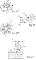
- a milling tool having a rotatable basic or tool body 1, which is equipped with a plurality of replaceable and indexable cutting inserts 2 according to the invention.
- the basic body 1 is rotatable on a centre axis designated C1, in relation to which a rotationally symmetrical envelope surface 3 is generated.
- the envelope surface 3 extends between a pair of opposite, front and rear ends 4, 5, which generally are flat and extend perpendicular to the centre axis C1.
- a reference plane RP is shown, which is parallel to the plane of the ends 4, 5 and extends perpendicular to the centre axis C1.
- the individual cutting inserts 2 is detachably mounted on a radially outer end of a cutting edge exchange mechanism 6, which is housed in a bore 7, which mouths in the envelope surface 3, more precisely in a transition between the same and the front end plane 4.
- a spring-loaded ejector 8 is included, by means of which the cutting insert can be thrust outward a distance from the basic body and simultaneously be turned from one index position to another.
- Fig. 1 it is shown how the ejectors for all cutting inserts have their inner ends 9 accessible from a central hollow space 10 in the basic body.
- the inner ends of the ejectors stick inward a distance in this hollow space, whereby all cutting inserts can be ejected by means of a suitable accessory, e.g., a mandrel, which can be pressed into the hollow space 10 and rectilinearly thrust out the ejectors 8, wherein these simultaneously are turned on their centre axes C2.
- a suitable accessory e.g., a mandrel
- the ejectors are spring-loaded by means of screw compression springs 11 (see Fig. 2 ), which automatically bring back the ejectors to their initial positions as soon as the mandrel is removed from the hollow space.
- the cutting insert 2 In its operative state, the cutting insert 2 is kept fixed in a seat 13 included in the cutting edge exchange mechanism (see Fig. 3 ), more precisely by means of a screw 14 (see Fig. 1 ), which, via a hole 15 in the cutting insert, can be tightened in a threaded hole 16, which is included in the movable ejector 8.
- the seat 13 is in the form of a rim of alternating cogs 17 and gashes 18, one of two flanks 19, 20 of each cog rising at a fairly steep flank angle (for rotational securing of the cutting insert), while the other flank leans at a flatter angle (for contributing to the turning of the cutting insert, when this is returned to an initial position).
- an interacting gear rim 21 In each one of two opposite sides of the cutting insert, there is included an interacting gear rim 21 having alternating cogs 22 and gashes 23. In the operative state, the two gear rims engage each other.
- the milling cutting inserts according to the invention are conventionally, or in another suitable way, mounted in a milling cutter body.
- the cutting inserts of such embodiments are provided with support surfaces and in certain embodiments also locking surfaces of another type.
- a support surface may, for example, be a surface on the inside of the cutting insert or along the periphery of the cutting insert, which is intended to abut against surfaces intended therefor in the seat of the milling cutter body.
- a locking surface may, for example, be situated on a ridge or in a groove and interacts with the corresponding surface of the corresponding member of the milling cutter body.
- the cutting inserts may be clamped in the seat of the milling cutter body by means of a screw or another suitable clamping device.
- the cutting insert includes a pair of opposite sides 24, 25, which are axially separated along a centre axis C3.
- the first-mentioned one is henceforth denominated outside and the last-mentioned one inside.
- the outside 24 is facing outward from the basic body, and the inside inward toward the same.
- the geometrical basic shape of the cutting insert is shown in simplified form, more precisely so far that the gear rims 21 have been eliminated and replaced by flat, ring-shaped surfaces, which have been designated hub portion 47 and 48.
- the cutting insert has a circular basic shape, which is represented by a dash-dotted circle S, the centre of which coincides with the centre axis C3.
- the cutting insert is double-sided and invertible by including two identical halves on both sides of a centre plane MP, which extends perpendicular to the centre axis C3 and is parallel to those planes in which the hub portions 47, 48 are located.
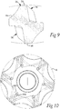
- Fig. 11 schematically shows a geometrical surface of revolution, which is assumed to surround the cutting insert.
- a plurality of part surfaces are included, a first one of which 26 - in the example - is conical and extends from the flat hub portion 47 to a first, circular boundary line 27 against a cross-sectionally convexly arched surface 28.
- This forms a so-called radius transition, which via a second boundary line 29 transforms into a second conical surface 30, which in turn - via a third boundary line 31 - transforms into a central girth surface 32, which may be cylindrical.
- the angle designated ⁇ between the cone surface 26 and the plane of the hub portion 24 is acute and amounts in the example to approx. 33°.
- the corresponding angle ⁇ between the cone surface 30 and said plane is considerably greater, and amounts in the example to approx. 83°.
- an imaginary generatrix along the cone surface 30 forms an angle of 7° with the centre axis C3.
- the surfaces 26, 28, 30 and 32 form an envelope surface generally designated 33 belonging to the outside.
- a plurality of chip channels 34 are countersunk in the individual envelope surface 33.
- Said chip channels are tangentially spaced-apart from each other via ridges 35, which individually include a cutting edge generally designated 36.
- ridges 35 which individually include a cutting edge generally designated 36.
- This is formed between, on one hand, a chip surface 37, which is included in the chip channel 34 and situated on a flank of the individual ridge 35, and, on the other hand, a clearance surface 38, which forms a crest or, in other words, a crown of the individual ridge 35.
- the cutting insert includes in total six cutting edges 36 per side, which cutting edges 36 have a uniform pitch of 60° (see Fig. 6 ).
- the cutting insert may have another number of cutting edges and accordingly also ridges/chip channels, more or fewer.
- the chip channel 34 is - in addition to the chip surface 37 - delimited by a bottom 39, the contour shape of which in plane elevation is determined by boundary lines 40, 41, 42, 43.
- the bottom 39 has the shape of a concavely double-arched surface, i.e., a softly arched surface, which is concave as viewed in a cross-section between the boundary lines 40, 42, as well as in a cross-section between the boundary lines 41, 43.
- the depth of the chip channel is the greatest nearest the boundary line 40 to successively decrease toward the boundary line 42.
- the chip channel 34 transforms into a ridge being in front.
- the individual cutting edge 36 (see Fig. 7 ) includes a main edge 36a, which extends between two radially separated end points, viz. an inner end point 45 and an outer one 46.
- the inner end point 45 is situated in the plane of the hub portion 47, while the outer one 46 is situated along the boundary line 27 (see also Fig. 11 ) between the cone surface 26 and the part surface 28.
- the main edge 36a transforms into a convex, arched secondary edge 36b, which extends between the boundary lines 27 and 29 of the part surface 28.
- the secondary edge 36b provides a concave transition between a shoulder cut-out by the main edge and the flat surface generated in the workpiece.
- the inner end point 45 of the main edge 36a is located at a greater axial distance from the centre plane MP (or the hub portion 25 of the inside of the cutting insert) than the outer end point 46.
- the cutting edge in its entirety designated 36, includes a plurality of different part edges, viz. the main edge designated 36a and the secondary edge 36b.
- the last-mentioned one extends between the radially outer end point 46 of the main edge 36a to an end point 47 (see the left part in Fig. 7 ).
- the last-mentioned one is situated along the geometrical boundary line 29 according to Fig. 11 , i.e., nearer the centre plane MP than the end point 46.
- Fig. 7 it is seen that the outer boundary line 43 of the bottom 39 of the chip channel is concavely curved and spaced apart radially inward from the circumscribed circle S that defines the periphery of the cutting insert. In such a way, a crescent-shaped opening or passage is formed between the chip channel and the flat surface generated in the workpiece. Through this opening, removed chips can freely pass from one side of the cutting insert toward the other.
- the two identical halves of the cutting insert on both sides in the centre plane MP are rotationally symmetrical over an axis in the centre plane, which intersects the centre axis so that all cutting edges on both sides should be mountable on a tool body rotating in one and the same direction.
- ridges 35 in which the cutting edges 36 are included and which are situated on opposite sides, will intersect each other when they are regarded in a transparent plane elevation, of the type shown in Fig. 10 , where the ridges turned upward from the plane of the drawing are designated 35a and the opposite ones 35b.
- This crosswise disposition of the ridges contributes significantly to a good strength and a long service life of the cutting insert.
- Fig. 7 it is seen that the main edge 36a of the individual cutting edge - as viewed in plane elevation - in its entirety is located tangentially behind an imaginary radius r between the centre axis C3 of the cutting insert and the end point 46.
- an edge designated 36c forms an integrated, chip removing part edge of the cutting edge 36.
- the main edge 36a and the part edge 36c form a right angle with each other. Therefore, during milling, the part edge 36c generates a flat bottom surface GS, and the main edge 36a a cylindrical surface, while the convex secondary edge 36b generates a concave transition surface (a so-called radius transition) between the cylinder surface and the flat bottom surface.
- the cutting insert is formed for quick milling-off of thin surface layers from a workpiece.
- the principal chip removal is carried out by means of the part edge 36c in combination with the secondary edge 36b, more precisely as a consequence of the setting angle of the cutting insert in an operative state being small, e.g. in the order of 1-5°.
- a cutting depth that is smaller than the radius of the secondary edge 36b is selected, involving that the part edge 36a only in exceptional cases is used for chip removal, e.g. when the surface of the workpiece is uneven.
- the cutting insert is formed for demanding milling at large cutting depths.
- the individual cutting edge 36 is arched along its entire length, more precisely as a consequence of the individual clearance surface 38 coinciding with a surface of revolution, the shape of which is determined by a circular arc-shaped generatrix.
- the cutting insert 2 In the operative state, which is shown in Figs. 2 and 12 , the cutting insert 2 assumes a tipped-in position in relation to the flat surface GS to be generated in the workpiece. To this surface GS, the centre axis C1 of the basic body 1 is perpendicular, and hence it follows that the cutting inserts are tilted in relation to the reference plane RP (see Fig. 2 ). In the example, the cutting insert assumes a position in which its centre axis C3 forms an angle ⁇ of 12° in relation to the surface GS. This means that the main cutting edge 36a of the cutting edge 36, as this is regarded in Fig.
- a primary advantage of the invention is that a large number of cutting edges can be formed in a cutting insert having a circular basic shape - irrespective of whether the cutting insert is single-sided or double-sided - without the size of the cutting insert becoming too large to allow mounting of the cutting insert in the available space in a milling cutter body.
- the cutting insert may in practice be formed with 5 to 7 cutting edges in the area of an outside and/or an inside.
- the cutting insert as a consequence of the clearance surfaces coinciding with a surface of revolution, can, if required, be precision ground to a micrometrical dimensional accuracy in respect of the shape and position of the different cutting edges in relation to the centre axis of the cutting insert.
- the cutting insert protects the basic body from the destructive impact of the chips.
- the invention is not limited only to the embodiments described above and shown in the drawings.
- the cutting insert may be formed with other rotationally securing means than the exemplified gear rims.
- the cutting insert could be formed with holes or female-like recesses, in which male-like members included in the basic body engage.
Landscapes
- Engineering & Computer Science (AREA)
- Mechanical Engineering (AREA)
- Milling Processes (AREA)
Claims (8)
- Indexierbarer Schneideinsatz für einen Fräser, welcher umfasst:ein Paar von gegenüberliegenden Außenseiten und Innenseiten (24, 25),einen Umfang (S),eine Vielzahl von einander entsprechenden und abwechselnd einzeln verwendbaren Schneidkanten (36) undeine Mittelachse (C3), welche sich zwischen den Außenseiten und den Innenseiten erstreckt,
wobeidie Schneidkanten (36) bezüglich der Mittelachse (C3) rotationssymmetrisch angeordnet sind, und wobeidie Außenseite (24) einen Nabenabschnitt (47) aufweist, welcher bezüglich der Mittelachse (C3) zentrisch angeordnet ist,
dadurch gekennzeichnet, dassdie Außenseite (24) eine Mehrzahl von Rippen (35) aufweist, welche sich von dem Nabenabschnitt (47) in Richtung des Umfangs (S) erstrecken,wobei eine Mehrzahl von Spankanälen (34) in der Außenseite (24) eingelassen sind,
wobeidie Spankanäle (34) in tangentialer Richtung durch die Rippen (35) voneinander beabstandet sind, wobei die Rippen jeweils eine der Schneidkanten (36) umfassen, und wobeijede der Schneidkanten (36) zwischen einerseits einer Spanfläche (37), welche auf einer Flanke der dazugehörigen Rippe (35) angeordnet ist und in einem ersten Spankanal (34) aufgenommen ist, und andererseits einer Freifläche (38), welche auf einem Scheitel der dazugehörigen Rippe (35) angeordnet ist und an einen zweiten Spankanal (34) angrenzt, gebildet ist. - Schneideinsatz nach Anspruch 1, dadurch gekennzeichnet, dass die Freifläche (38) in beliebigen Schnitten quer zu der Rippe (35) eine konvex gebogene Form hat, und zwar indem sie mit einer geometrischen Rotationsfläche einer Umdrehung (26) zusammenfällt, die zwischen dem Nabenabschnitt (47) und dem Umfang (S) angeordnet ist.
- Schneideinsatz nach Anspruch 1 oder 2, dadurch gekennzeichnet, dass der einzelne Spankanal (34) eine Tiefe aufweist, die nahe der Spanfläche (37) am größten ist, und die sich in Richtung zu einem Ende schrittweise verringert, an dem der Spankanal in eine davorliegende Rippe (35) übergeht.
- Schneideinsatz nach einem der vorherigen Ansprüche, dadurch gekennzeichnet, dass der Boden (39) des Spankanals (35) eine doppelt konkav gekrümmte Fläche ist.
- Schneideinsatz nach einem der vorherigen Ansprüche, dadurch gekennzeichnet, dass eine umfangsseitig äußere Begrenzungslinie (43) des Spankanals konkav gekrümmt ist und radial nach innen von einem Umkreis (S) beabstandet ist, welcher den Umfang des Schneideinsatzes bestimmt.
- Schneideinsatz nach einem der vorherigen Ansprüche, dadurch gekennzeichnet, dass zumindest der Hauptteil der Hauptkante einer jeweiligen Schneidkante - in ebener Draufsicht - in tangentialer Richtung hinter einem imaginären Radius r zwischen der Mittelachse des Schneideinsatzes und einem Endpunkt der Hauptkante angeordnet ist, der dem Umfang am nächsten liegt.
- Schneideinsatz nach einem der vorherigen Ansprüche, dadurch gekennzeichnet, dass dieser doppelseitig und wendbar ist, indem zwei identische Hälften auf beiden Seiten einer Mittelebene (MP), welche sich senkrecht zu der Mittelachse (C3) erstreckt, aufweist sind, wobei die Hälften bezüglich einer Achse in der Mittelebene, welche die Mittelachse (C3) kreuzt, rotationssymmetrisch sind.
- Schneideinsatz nach Anspruch 7, dadurch gekennzeichnet, dass sich die in den entsprechenden Hälften aufgenommenen Erhöhungen (35), aus einer gedachten, ebenen Draufsichtprojektion paarweise kreuzen.
Priority Applications (4)
| Application Number | Priority Date | Filing Date | Title |
|---|---|---|---|
| EP14164906.1A EP2933048B1 (de) | 2014-04-16 | 2014-04-16 | Wendeschneidplatte für ein fräswerkzeug |
| PCT/EP2015/053369 WO2015158449A1 (en) | 2014-04-16 | 2015-02-18 | An indexable milling cutting insert |
| US15/303,643 US9782845B2 (en) | 2014-04-16 | 2015-02-18 | Indexable milling cutting insert |
| CN201580019027.8A CN106170358B (zh) | 2014-04-16 | 2015-02-18 | 可转位的铣削切削刀片 |
Applications Claiming Priority (1)
| Application Number | Priority Date | Filing Date | Title |
|---|---|---|---|
| EP14164906.1A EP2933048B1 (de) | 2014-04-16 | 2014-04-16 | Wendeschneidplatte für ein fräswerkzeug |
Publications (2)
| Publication Number | Publication Date |
|---|---|
| EP2933048A1 EP2933048A1 (de) | 2015-10-21 |
| EP2933048B1 true EP2933048B1 (de) | 2017-02-01 |
Family
ID=50942021
Family Applications (1)
| Application Number | Title | Priority Date | Filing Date |
|---|---|---|---|
| EP14164906.1A Not-in-force EP2933048B1 (de) | 2014-04-16 | 2014-04-16 | Wendeschneidplatte für ein fräswerkzeug |
Country Status (4)
| Country | Link |
|---|---|
| US (1) | US9782845B2 (de) |
| EP (1) | EP2933048B1 (de) |
| CN (1) | CN106170358B (de) |
| WO (1) | WO2015158449A1 (de) |
Families Citing this family (2)
| Publication number | Priority date | Publication date | Assignee | Title |
|---|---|---|---|---|
| EP3587011B1 (de) * | 2018-06-21 | 2021-04-21 | AB Sandvik Coromant | Indexierungssystem für ein fräswerkzeug |
| US20250269442A1 (en) * | 2024-02-28 | 2025-08-28 | Iscar, Ltd. | Cutting tool and indexable cutting insert having a plurality of circumferential cutting portions and a central mounting portion |
Family Cites Families (13)
| Publication number | Priority date | Publication date | Assignee | Title |
|---|---|---|---|---|
| JP3003230B2 (ja) * | 1991-02-05 | 2000-01-24 | 三菱マテリアル株式会社 | スローアウェイチップ及びスローアウェイ式カッタ |
| DE10326662A1 (de) * | 2003-06-11 | 2005-01-05 | Sandvik Ab | Schneideinsatz zum Drehen und Fräsen |
| SE531850C2 (sv) * | 2007-12-13 | 2009-08-25 | Seco Tools Ab | Skär och verktyg för spånavskiljande bearbetning |
| SE533269C2 (sv) * | 2008-12-17 | 2010-08-03 | Sandvik Intellectual Property | Dubbelsidigt, indexerbart planfrässkär |
| CN102264495B (zh) * | 2009-02-26 | 2014-05-21 | 京瓷株式会社 | 切削镶刀及切削工具、以及使用该切削工具的被切削件的切削方法 |
| US9475132B2 (en) * | 2009-10-15 | 2016-10-25 | Sandvik, Inc. | Multiteeth indexable insert with locating means and material removal tool with same |
| IL210966A (en) | 2011-01-31 | 2015-06-30 | Iscar Ltd | Tangential and milling |
| EP2680992A1 (de) * | 2011-02-28 | 2014-01-08 | CeramTec GmbH | Fräser für die hartzerspanung |
| EP2596889B1 (de) * | 2011-11-23 | 2017-04-26 | Sandvik Intellectual Property AB | Schneideinsatz und Fräser |
| ES2657114T3 (es) * | 2011-11-25 | 2018-03-01 | Sumitomo Electric Hardmetal Corp. | Accesorio de corte indexable para fresado |
| SE536343C2 (sv) * | 2012-01-16 | 2013-09-03 | Sandvik Intellectual Property | Fräsverktyg jämte dubbelsidigt indexerbart frässkär |
| SE536344C2 (sv) * | 2012-01-30 | 2013-09-03 | Sandvik Intellectual Property | Fräsverktyg jämte frässkär där skäreggen har spetsig stigningsvinkel |
| US8573905B2 (en) * | 2012-03-22 | 2013-11-05 | Iscar, Ltd. | Triangular cutting insert and cutting tool |
-
2014
- 2014-04-16 EP EP14164906.1A patent/EP2933048B1/de not_active Not-in-force
-
2015
- 2015-02-18 WO PCT/EP2015/053369 patent/WO2015158449A1/en not_active Ceased
- 2015-02-18 US US15/303,643 patent/US9782845B2/en not_active Expired - Fee Related
- 2015-02-18 CN CN201580019027.8A patent/CN106170358B/zh not_active Expired - Fee Related
Non-Patent Citations (1)
| Title |
|---|
| None * |
Also Published As
| Publication number | Publication date |
|---|---|
| US9782845B2 (en) | 2017-10-10 |
| CN106170358B (zh) | 2018-09-18 |
| CN106170358A (zh) | 2016-11-30 |
| WO2015158449A1 (en) | 2015-10-22 |
| EP2933048A1 (de) | 2015-10-21 |
| US20170036280A1 (en) | 2017-02-09 |
Similar Documents
| Publication | Publication Date | Title |
|---|---|---|
| CA2956392C (en) | Double-sided cutting insert and milling tool | |
| EP2620243B1 (de) | Fräser sowie Fräseinsatz | |
| JP5475808B2 (ja) | 切削加工用の回転工具及び切削インサート | |
| EP3308891B1 (de) | T-nut-schneider | |
| JP7098538B2 (ja) | 表および裏面取り用回転式フライスのための星形切削インサート | |
| CA2689115C (en) | Adjustable indexable drill | |
| CN103658799B (zh) | 铣削刀具 | |
| CN103252538B (zh) | 面滚铣刀系统及用于该面滚铣刀系统的可转位铣削刀片 | |
| WO2002092267A9 (en) | Cutting tool with improved insert seat arrangement for indexable cutting inserts | |
| US9796028B2 (en) | Prismatic and cylindrical cutting inserts | |
| EP3233340B1 (de) | Drehschneidwerkzeug mit einer vorgegebenen anzahl von links- und rechtsläufigen spiralnuten und stirnschneidzähnen | |
| US12434309B2 (en) | Milling cutter and blade part thereof | |
| US10384276B2 (en) | Insert type tool and thread mill | |
| WO2016009995A1 (ja) | 刃先交換式回転切削工具 | |
| EP2764938B1 (de) | Vorrichtung zur spanabhebenden Bearbeitung | |
| US9782845B2 (en) | Indexable milling cutting insert | |
| US9981324B2 (en) | Milling tool | |
| US20180133823A1 (en) | Reamer | |
| JP2015196203A (ja) | 刃先交換式メタルソー | |
| JP2021065937A (ja) | 切削インサートおよび刃先交換式切削工具 | |
| JP2011121134A (ja) | 刃先交換式カッタ |
Legal Events
| Date | Code | Title | Description |
|---|---|---|---|
| PUAI | Public reference made under article 153(3) epc to a published international application that has entered the european phase |
Free format text: ORIGINAL CODE: 0009012 |
|
| AK | Designated contracting states |
Kind code of ref document: A1 Designated state(s): AL AT BE BG CH CY CZ DE DK EE ES FI FR GB GR HR HU IE IS IT LI LT LU LV MC MK MT NL NO PL PT RO RS SE SI SK SM TR |
|
| AX | Request for extension of the european patent |
Extension state: BA ME |
|
| 17P | Request for examination filed |
Effective date: 20160421 |
|
| RBV | Designated contracting states (corrected) |
Designated state(s): AL AT BE BG CH CY CZ DE DK EE ES FI FR GB GR HR HU IE IS IT LI LT LU LV MC MK MT NL NO PL PT RO RS SE SI SK SM TR |
|
| GRAP | Despatch of communication of intention to grant a patent |
Free format text: ORIGINAL CODE: EPIDOSNIGR1 |
|
| INTG | Intention to grant announced |
Effective date: 20160927 |
|
| GRAS | Grant fee paid |
Free format text: ORIGINAL CODE: EPIDOSNIGR3 |
|
| GRAA | (expected) grant |
Free format text: ORIGINAL CODE: 0009210 |
|
| AK | Designated contracting states |
Kind code of ref document: B1 Designated state(s): AL AT BE BG CH CY CZ DE DK EE ES FI FR GB GR HR HU IE IS IT LI LT LU LV MC MK MT NL NO PL PT RO RS SE SI SK SM TR |
|
| REG | Reference to a national code |
Ref country code: GB Ref legal event code: FG4D |
|
| REG | Reference to a national code |
Ref country code: CH Ref legal event code: EP Ref country code: AT Ref legal event code: REF Ref document number: 865133 Country of ref document: AT Kind code of ref document: T Effective date: 20170215 |
|
| REG | Reference to a national code |
Ref country code: IE Ref legal event code: FG4D |
|
| REG | Reference to a national code |
Ref country code: DE Ref legal event code: R096 Ref document number: 602014006463 Country of ref document: DE |
|
| REG | Reference to a national code |
Ref country code: FR Ref legal event code: PLFP Year of fee payment: 4 |
|
| PGFP | Annual fee paid to national office [announced via postgrant information from national office to epo] |
Ref country code: FR Payment date: 20170324 Year of fee payment: 4 |
|
| REG | Reference to a national code |
Ref country code: NL Ref legal event code: MP Effective date: 20170201 |
|
| REG | Reference to a national code |
Ref country code: LT Ref legal event code: MG4D |
|
| REG | Reference to a national code |
Ref country code: AT Ref legal event code: MK05 Ref document number: 865133 Country of ref document: AT Kind code of ref document: T Effective date: 20170201 |
|
| PG25 | Lapsed in a contracting state [announced via postgrant information from national office to epo] |
Ref country code: LT Free format text: LAPSE BECAUSE OF FAILURE TO SUBMIT A TRANSLATION OF THE DESCRIPTION OR TO PAY THE FEE WITHIN THE PRESCRIBED TIME-LIMIT Effective date: 20170201 Ref country code: FI Free format text: LAPSE BECAUSE OF FAILURE TO SUBMIT A TRANSLATION OF THE DESCRIPTION OR TO PAY THE FEE WITHIN THE PRESCRIBED TIME-LIMIT Effective date: 20170201 Ref country code: NO Free format text: LAPSE BECAUSE OF FAILURE TO SUBMIT A TRANSLATION OF THE DESCRIPTION OR TO PAY THE FEE WITHIN THE PRESCRIBED TIME-LIMIT Effective date: 20170501 Ref country code: HR Free format text: LAPSE BECAUSE OF FAILURE TO SUBMIT A TRANSLATION OF THE DESCRIPTION OR TO PAY THE FEE WITHIN THE PRESCRIBED TIME-LIMIT Effective date: 20170201 Ref country code: GR Free format text: LAPSE BECAUSE OF FAILURE TO SUBMIT A TRANSLATION OF THE DESCRIPTION OR TO PAY THE FEE WITHIN THE PRESCRIBED TIME-LIMIT Effective date: 20170502 Ref country code: IS Free format text: LAPSE BECAUSE OF FAILURE TO SUBMIT A TRANSLATION OF THE DESCRIPTION OR TO PAY THE FEE WITHIN THE PRESCRIBED TIME-LIMIT Effective date: 20170601 |
|
| PG25 | Lapsed in a contracting state [announced via postgrant information from national office to epo] |
Ref country code: NL Free format text: LAPSE BECAUSE OF NON-PAYMENT OF DUE FEES Effective date: 20170201 Ref country code: BG Free format text: LAPSE BECAUSE OF FAILURE TO SUBMIT A TRANSLATION OF THE DESCRIPTION OR TO PAY THE FEE WITHIN THE PRESCRIBED TIME-LIMIT Effective date: 20170501 Ref country code: AT Free format text: LAPSE BECAUSE OF FAILURE TO SUBMIT A TRANSLATION OF THE DESCRIPTION OR TO PAY THE FEE WITHIN THE PRESCRIBED TIME-LIMIT Effective date: 20170201 Ref country code: PT Free format text: LAPSE BECAUSE OF FAILURE TO SUBMIT A TRANSLATION OF THE DESCRIPTION OR TO PAY THE FEE WITHIN THE PRESCRIBED TIME-LIMIT Effective date: 20170601 Ref country code: ES Free format text: LAPSE BECAUSE OF FAILURE TO SUBMIT A TRANSLATION OF THE DESCRIPTION OR TO PAY THE FEE WITHIN THE PRESCRIBED TIME-LIMIT Effective date: 20170201 Ref country code: PL Free format text: LAPSE BECAUSE OF FAILURE TO SUBMIT A TRANSLATION OF THE DESCRIPTION OR TO PAY THE FEE WITHIN THE PRESCRIBED TIME-LIMIT Effective date: 20170201 Ref country code: RS Free format text: LAPSE BECAUSE OF FAILURE TO SUBMIT A TRANSLATION OF THE DESCRIPTION OR TO PAY THE FEE WITHIN THE PRESCRIBED TIME-LIMIT Effective date: 20170201 Ref country code: SE Free format text: LAPSE BECAUSE OF FAILURE TO SUBMIT A TRANSLATION OF THE DESCRIPTION OR TO PAY THE FEE WITHIN THE PRESCRIBED TIME-LIMIT Effective date: 20170201 Ref country code: LV Free format text: LAPSE BECAUSE OF FAILURE TO SUBMIT A TRANSLATION OF THE DESCRIPTION OR TO PAY THE FEE WITHIN THE PRESCRIBED TIME-LIMIT Effective date: 20170201 |
|
| PG25 | Lapsed in a contracting state [announced via postgrant information from national office to epo] |
Ref country code: CZ Free format text: LAPSE BECAUSE OF FAILURE TO SUBMIT A TRANSLATION OF THE DESCRIPTION OR TO PAY THE FEE WITHIN THE PRESCRIBED TIME-LIMIT Effective date: 20170201 Ref country code: SK Free format text: LAPSE BECAUSE OF FAILURE TO SUBMIT A TRANSLATION OF THE DESCRIPTION OR TO PAY THE FEE WITHIN THE PRESCRIBED TIME-LIMIT Effective date: 20170201 Ref country code: EE Free format text: LAPSE BECAUSE OF FAILURE TO SUBMIT A TRANSLATION OF THE DESCRIPTION OR TO PAY THE FEE WITHIN THE PRESCRIBED TIME-LIMIT Effective date: 20170201 Ref country code: RO Free format text: LAPSE BECAUSE OF FAILURE TO SUBMIT A TRANSLATION OF THE DESCRIPTION OR TO PAY THE FEE WITHIN THE PRESCRIBED TIME-LIMIT Effective date: 20170201 Ref country code: IT Free format text: LAPSE BECAUSE OF FAILURE TO SUBMIT A TRANSLATION OF THE DESCRIPTION OR TO PAY THE FEE WITHIN THE PRESCRIBED TIME-LIMIT Effective date: 20170201 |
|
| REG | Reference to a national code |
Ref country code: DE Ref legal event code: R097 Ref document number: 602014006463 Country of ref document: DE |
|
| PG25 | Lapsed in a contracting state [announced via postgrant information from national office to epo] |
Ref country code: SM Free format text: LAPSE BECAUSE OF FAILURE TO SUBMIT A TRANSLATION OF THE DESCRIPTION OR TO PAY THE FEE WITHIN THE PRESCRIBED TIME-LIMIT Effective date: 20170201 Ref country code: DK Free format text: LAPSE BECAUSE OF FAILURE TO SUBMIT A TRANSLATION OF THE DESCRIPTION OR TO PAY THE FEE WITHIN THE PRESCRIBED TIME-LIMIT Effective date: 20170201 |
|
| REG | Reference to a national code |
Ref country code: CH Ref legal event code: PL |
|
| PLBE | No opposition filed within time limit |
Free format text: ORIGINAL CODE: 0009261 |
|
| STAA | Information on the status of an ep patent application or granted ep patent |
Free format text: STATUS: NO OPPOSITION FILED WITHIN TIME LIMIT |
|
| 26N | No opposition filed |
Effective date: 20171103 |
|
| REG | Reference to a national code |
Ref country code: IE Ref legal event code: MM4A |
|
| PG25 | Lapsed in a contracting state [announced via postgrant information from national office to epo] |
Ref country code: MC Free format text: LAPSE BECAUSE OF FAILURE TO SUBMIT A TRANSLATION OF THE DESCRIPTION OR TO PAY THE FEE WITHIN THE PRESCRIBED TIME-LIMIT Effective date: 20170201 |
|
| PG25 | Lapsed in a contracting state [announced via postgrant information from national office to epo] |
Ref country code: LI Free format text: LAPSE BECAUSE OF NON-PAYMENT OF DUE FEES Effective date: 20170430 Ref country code: CH Free format text: LAPSE BECAUSE OF NON-PAYMENT OF DUE FEES Effective date: 20170430 Ref country code: LU Free format text: LAPSE BECAUSE OF NON-PAYMENT OF DUE FEES Effective date: 20170416 Ref country code: SI Free format text: LAPSE BECAUSE OF FAILURE TO SUBMIT A TRANSLATION OF THE DESCRIPTION OR TO PAY THE FEE WITHIN THE PRESCRIBED TIME-LIMIT Effective date: 20170201 |
|
| REG | Reference to a national code |
Ref country code: BE Ref legal event code: MM Effective date: 20170430 |
|
| PG25 | Lapsed in a contracting state [announced via postgrant information from national office to epo] |
Ref country code: IE Free format text: LAPSE BECAUSE OF NON-PAYMENT OF DUE FEES Effective date: 20170416 |
|
| PG25 | Lapsed in a contracting state [announced via postgrant information from national office to epo] |
Ref country code: BE Free format text: LAPSE BECAUSE OF NON-PAYMENT OF DUE FEES Effective date: 20170430 |
|
| PG25 | Lapsed in a contracting state [announced via postgrant information from national office to epo] |
Ref country code: MT Free format text: LAPSE BECAUSE OF NON-PAYMENT OF DUE FEES Effective date: 20170416 |
|
| GBPC | Gb: european patent ceased through non-payment of renewal fee |
Effective date: 20180416 |
|
| PG25 | Lapsed in a contracting state [announced via postgrant information from national office to epo] |
Ref country code: GB Free format text: LAPSE BECAUSE OF NON-PAYMENT OF DUE FEES Effective date: 20180416 |
|
| PG25 | Lapsed in a contracting state [announced via postgrant information from national office to epo] |
Ref country code: FR Free format text: LAPSE BECAUSE OF NON-PAYMENT OF DUE FEES Effective date: 20180430 |
|
| PG25 | Lapsed in a contracting state [announced via postgrant information from national office to epo] |
Ref country code: HU Free format text: LAPSE BECAUSE OF FAILURE TO SUBMIT A TRANSLATION OF THE DESCRIPTION OR TO PAY THE FEE WITHIN THE PRESCRIBED TIME-LIMIT; INVALID AB INITIO Effective date: 20140416 |
|
| PGFP | Annual fee paid to national office [announced via postgrant information from national office to epo] |
Ref country code: DE Payment date: 20190402 Year of fee payment: 6 |
|
| PG25 | Lapsed in a contracting state [announced via postgrant information from national office to epo] |
Ref country code: CY Free format text: LAPSE BECAUSE OF FAILURE TO SUBMIT A TRANSLATION OF THE DESCRIPTION OR TO PAY THE FEE WITHIN THE PRESCRIBED TIME-LIMIT Effective date: 20170201 |
|
| PG25 | Lapsed in a contracting state [announced via postgrant information from national office to epo] |
Ref country code: MK Free format text: LAPSE BECAUSE OF FAILURE TO SUBMIT A TRANSLATION OF THE DESCRIPTION OR TO PAY THE FEE WITHIN THE PRESCRIBED TIME-LIMIT Effective date: 20170201 |
|
| PG25 | Lapsed in a contracting state [announced via postgrant information from national office to epo] |
Ref country code: TR Free format text: LAPSE BECAUSE OF FAILURE TO SUBMIT A TRANSLATION OF THE DESCRIPTION OR TO PAY THE FEE WITHIN THE PRESCRIBED TIME-LIMIT Effective date: 20170201 |
|
| PG25 | Lapsed in a contracting state [announced via postgrant information from national office to epo] |
Ref country code: AL Free format text: LAPSE BECAUSE OF FAILURE TO SUBMIT A TRANSLATION OF THE DESCRIPTION OR TO PAY THE FEE WITHIN THE PRESCRIBED TIME-LIMIT Effective date: 20170201 |
|
| REG | Reference to a national code |
Ref country code: DE Ref legal event code: R119 Ref document number: 602014006463 Country of ref document: DE |
|
| PG25 | Lapsed in a contracting state [announced via postgrant information from national office to epo] |
Ref country code: DE Free format text: LAPSE BECAUSE OF NON-PAYMENT OF DUE FEES Effective date: 20201103 |