EP2933053A1 - Dispositif pour connecter des tubes - Google Patents
Dispositif pour connecter des tubes Download PDFInfo
- Publication number
- EP2933053A1 EP2933053A1 EP15163415.1A EP15163415A EP2933053A1 EP 2933053 A1 EP2933053 A1 EP 2933053A1 EP 15163415 A EP15163415 A EP 15163415A EP 2933053 A1 EP2933053 A1 EP 2933053A1
- Authority
- EP
- European Patent Office
- Prior art keywords
- pipes
- frame
- pipe coupler
- coupler according
- roller
- Prior art date
- Legal status (The legal status is an assumption and is not a legal conclusion. Google has not performed a legal analysis and makes no representation as to the accuracy of the status listed.)
- Granted
Links
- 238000005096 rolling process Methods 0.000 claims abstract description 12
- 238000005304 joining Methods 0.000 claims abstract description 8
- 238000003466 welding Methods 0.000 claims description 20
- 238000004804 winding Methods 0.000 claims description 6
- 239000000463 material Substances 0.000 claims description 4
- 239000002184 metal Substances 0.000 claims description 3
- 239000004033 plastic Substances 0.000 claims description 3
- 238000010276 construction Methods 0.000 description 2
- 230000008878 coupling Effects 0.000 description 2
- 238000010168 coupling process Methods 0.000 description 2
- 238000005859 coupling reaction Methods 0.000 description 2
- 238000004519 manufacturing process Methods 0.000 description 2
- 230000000694 effects Effects 0.000 description 1
- 238000003860 storage Methods 0.000 description 1
Images


Classifications
-
- B—PERFORMING OPERATIONS; TRANSPORTING
- B23—MACHINE TOOLS; METAL-WORKING NOT OTHERWISE PROVIDED FOR
- B23K—SOLDERING OR UNSOLDERING; WELDING; CLADDING OR PLATING BY SOLDERING OR WELDING; CUTTING BY APPLYING HEAT LOCALLY, e.g. FLAME CUTTING; WORKING BY LASER BEAM
- B23K37/00—Auxiliary devices or processes, not specially adapted for a procedure covered by only one of the other main groups of this subclass
- B23K37/04—Auxiliary devices or processes, not specially adapted for a procedure covered by only one of the other main groups of this subclass for holding or positioning work
- B23K37/053—Auxiliary devices or processes, not specially adapted for a procedure covered by only one of the other main groups of this subclass for holding or positioning work aligning cylindrical work; Clamping devices therefor
- B23K37/0533—External pipe alignment clamps
Definitions
- the present invention relates to a pipe coupler and in particular a coupler used to seam weld two ends of two cylindrical pipes.
- the invention can be used particularly in the production field of medium and large sized pipelines, such as oil pipelines, gas pipelines or the like.
- pipelines are typically assembled at the construction site, joining various tubular sections arranged aligned with one another along the edge of a trench by welding.
- Couplers For this purpose, the two ends of the pipes are held in position, against each other, by special devices named "couplers”.
- coupling devices are also configured to align the end edges of the two pipes along a circular profile that substantially coincides with the nominal diameter of the pipe.
- couplers are generally divided into two different types, internal couplers and external couplers.
- the invention relates in particular to the second type.
- Known external couplers generally comprise a pair of semi-circular jaws that are clamped around the pipes over the joining area. On the jaws there are arranged a plurality of gauge blocks adapted to contact the outer surface of the pipes, constraining the two ends of the pipes along their axis.
- Each of these gauge blocks is also provided with a screw, or a bolt, arranged radially with respect to the axis of the pipe and passing through the block so as to be able to contact the outer surface thereof.
- the two ends of the pipes are moved into contact with each other and enclosed between the jaws of the coupler.
- the screws of the various gauge blocks are clamped to a greater or lesser degree, so as to press against the surface of the pipes, elastically deforming their edges until they are perfectly aligned with each other.
- the couplers described above can be fitted to pipes having a specific outer diameter as, when the jaws are clamped, the gauge blocks are arranged along a circumference with a diameter that must coincide with the outer diameter of the pipe.
- the clamping step is performed manually by an operator, who must check alignment of the edges along the whole circumference of the pipes.
- One more disadvantage is represented by the difficulty encountered by the operator carrying out seam welding in the limited spaces between the two jaws, above all in the lower part of the pipes, which are generally raised off the ground by only a few tens of centimeters.
- the object of the present invention is to provide a pipe coupler that solves the problems of the prior art described above.
- Another object of the present invention is to produce a pipe coupler that can be used, efficiently, with pipes of different diameters.
- a further object of the present invention is that of providing a pipe coupler that allows the welding operator to weld in simpler manner with respect to known systems.
- a pipe coupler comprising a frame that defines an open housing in which the ends of two pipes to be welded are at least partially contained, and rolling means, facing each other in said housing to contact the outer surface of the pipes, configured to allow relative rotation between the frame and said pipes.
- the rolling means comprise at least one roller placed in proximity of the joining area of the two pipes, so as to contact the outer surfaces of both the pipes.
- the outer surface of said roller is provided with thrust means adapted to exert, following rotation in contact with the surfaces of the pipes, two opposing forces, acting on the respective ends of the two pipes to hold them against each other.
- the rolling means which contact the outer surfaces of the pipes, have the task of aligning their end edges so that they can be joined by welding.
- the aforesaid at least one roller also allows said end edges to be held facing and in contact with each other.
- the open housing allows the coupler to be fitted rapidly and simply to the ends of the pipes, without manual operations by one or more operators.
- the thrust means comprise a first helical profile, produced on a first segment of the roller, with a first winding direction, and a second helical profile, produced on a second segment of the roller, with a second winding direction opposite the first.
- the helical profiles are made of metal, so as to ensure resistance to contact pressures that are generated with the surface of the pipes.
- a spiral made of plastic or rubber material, adapted to contact the surface of the pipes.
- This material coming into contact with the outer surface of the pipes, allows the friction between the rollers and the surfaces of the pipes to be increased, increasing the intensity of the axial forces generated.
- a projecting annular portion with two stop surfaces adapted to contact the respective edges of the ends of the pipes.
- this annular portion has a substantially rectangular section having the two stop surfaces converging toward each other.
- This variant can be used when the pipes have tapered or beveled end edges to create an annular seat adapted to contain the seam weld.
- the rolling means comprise a plurality of rollers connected to the frame, directly or indirectly, so as to rotate about an axis parallel to the axis of the pipes.
- rollers can be provided with the thrust means described above.
- At least one of said rollers is connected to motor means.
- Said motor means allow relative rotation between the frame and the pipes.
- the coupler can be used holding the pipes fixed and rotating the frame around them.
- the rolling means can be movable inside the housing.
- the coupler can be used to couple pipes of different diameters.
- the frame comprises an arc-shaped structure with a substantially semi-circular inner edge.
- Said roller can be connected, directly or indirectly, to the arc-shaped structure.
- At least a first pair of coupled rollers is supported in a rotating manner by said movable portion.
- the movable portion allows the rollers to be carried from an idle position, in which the frame can be arranged around the pipes, to an operating position in which they contact the surfaces of the pipes.
- a second movable portion connected to actuator means adapted to move it in the housing. At least a second pair of rollers is supported in a rotating manner by said movable portion.
- the first, the second, or both movable portions can be connected directly to an actuator.
- the movable portion is hinged on the arc-shaped structure or, alternatively, is hinged on an arm, in turn hinged on the arc-shaped structure, connected to actuator means.
- At least a first roller is provided with thrust means adapted to exert on the end of the two pipes two opposing forces, acting to hold them against each other when the relative rotation between the frame and the pipes takes place in a first rotation direction
- at least a second roller is provided with thrust means adapted to exert on the end of the two pipes two opposing forces, acting to hold them against each other when the relative rotation between the frame and the pipes takes place in a second rotation direction, opposite the first.
- the first roller or the second roller is selectively carried into contact with the pipes as a function of the rotation direction that is to be imparted to the frame.
- the coupler is provided with a welding device applied to the frame and configured to seam weld the ends of the pipes during relative rotation between the frame and the pipes.
- the coupler thus configured is therefore able to automatically position two pipes correctly and to join them by seam welding.
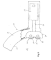
- the pipe coupler indicated as a whole with 1, comprises a frame 10 structured to define an open housing 11, in which the ends of two pipes T1, T2, to be joined to each other by welding, are partly contained.
- said frame 10 comprises, for example, an arc-shaped structure 12 with an inner edge 13 having a substantially semi-circular profile that partly surrounds the pipes T1, T2.
- rolling means for example rollers, facing the housing 11 and configured to allow relative rotation between the frame 10 and the pipes T1, T2.
- these rollers are connected to the frame 10 so as to rotate each around an axis parallel to the axis of the pipes T1, T2.
- the coupler comprises a first pair of rollers 14, 15 arranged along the inner edge 13 of the arc-shaped structure 12.
- Said rollers 14, 15 are preferably coupled, i.e. side by side but with the respective surfaces not in contact.
- rollers 14, 15 are mounted on the arc-shaped structure 12 so that their outer surface 14' and 15' projects beyond the inner edge 13 so as to come into contact with the outer surfaces T1' and T2' of pipes T1, T2 contained in the housing 11.
- the coupler also comprises a second pair of coupled rollers 22, 23 projecting toward the housing 11.
- this second pair of rollers 22, 23 is supported by a movable portion 20 connected to actuator means 21 adapted to move it inside the housing 11 toward or away from the first pair of rollers 14, 15.
- the coupler can be fitted to pipes with different outer diameters.
- the outermost rollers 14 and 22 are arranged so that their distance measured on a circular arc, inside the housing, is greater than 180 °, for example at least 190 °.
- the actuator means comprise a hydraulic cylinder 21 connected to the frame 10 provided with a rod 26 connected to the movable portion 20.
- the cylinder 21 can be connected to the movable portion and the rod 26 can be connected to the frame 10.
- the frame is provided with a flange 16 in which there are produced a plurality of seats 17 adapted to house a pin 19 that connects the hydraulic cylinder 21 to the frame.
- At least one of said rollers 14, 15, 22, 23 is placed in proximity of the joining area of the two pipes T1, T2, so as to contact the outer surfaces of both.
- At least one of these rollers comprises a first segment L1 and a second segment L2, between which there is interposed an annular projection 25.
- This annular projection 25 is preferably placed along the centerline of the roller defining two segments L1 and L2 of the same length.
- this annular projection is adapted to contact the end edges B1, B2 of the respective pipes T1, T2, when these are held against each other for welding.
- said annular portion 25 has a substantially triangular section, so as to define two inclined and converging stop surfaces 25'.
- the first segment L1 has the outer surface provided with a first projecting helical profile P1 with a first winding direction and the second segment L2 having the outer surface provided with a second helical profile P2 with a second winding direction opposite the first ( Fig. 8 ).
- Each of the two segments L1 and L2 is configured to rotate in contact with the outer surface of a portion of pipe.
- the profiles P1, P2 generate, through friction between the crests and the surfaces of the pipes, two opposing forces F1, F2 parallel to the axis of the pipes and opposite each other that tend move the two pipes T1, T2 toward each other.
- said helical profiles P1, P2 are made of metal so as to be able to withstand the pressure with which the rollers are pressed by the actuator 21 against the outer surfaces of the pipes.
- a spiral M made of plastic or rubber material, that allows the friction force between the roller and the pipes, and therefore the intensity of the forces F1, F2 that hold the two pipes against each other, to be increased.
- rollers 14, 15, 22, 23 have the structure described above.
- At least one of the rollers is connected to motor means 18 adapted to generate the torque required to rotate the frame 10 around the two pipes T1, T2.
- a hydraulic motor 18 is connected to the first pair of rollers 14, 15 mounted in a fixed manner on the arc-shaped structure 12.
- rollers can be connected to motor means adapted to rotate them.
- the actuator 21 is operated to translate the movable portion 20 toward the inside of the housing so that the pipes T1, T2 are clamped between the two pairs of rollers 14, 15, 22, 23.
- the hydraulic motor 18 is operated to rotate the rollers 14, 15 with respect to the surface of the pipes.
- Rotation of these rollers causes the rotation of the frame 10 around the pipes T1, T2 and also the generation of the forces F1, F2 that hold the two ends thrust toward each other.
- the welding operator can then seam weld the area in which the pipes are not surrounded by the frame 10 in a more convenient and simpler manner.
- the hydraulic motor 18 is provided with a control system to control the rotation speed of the frame with respect to the pipes T1, T2.
- This rotation can take place continuously or discretely, at the convenience of the welding operator.
- Figs. 9 and 10 show another variant of the coupler, indicated as a whole with 100.
- this variant at a first end of this arc-shaped structure there is hinged an arm 130 connected to an actuator 121. On the arm 130 there is hinged a first movable portion 120.
- the movable portion 120 can therefore swivel freely with respect to the arm 130.
- the extension of the actuator 121 rotates the arm 130, which in turn moves the movable portion inside the housing to carry the rollers 122, 123 into contact with the surface of the pipes T1, T2.
- a roller 114 On a second opposite end of the arc-shaped structure 112 there is placed a roller 114, the axis of which is fixed with respect to the arc-shaped structure 112.
- At least one of the rollers 114, 122, 123 is motorized to rotate the frame.
- a welding device 50 adapted to seam weld the end edges of the pipes while the coupler is rotated about the axis of the pipes. This device is already known and will not be described in more detail.
- the welding device 50 can be associated with guide means adapted to regulate the rotation speed of the frame, and therefore of the welding device, to obtain a seam weld that is as uniform as possible.
- Said guide means comprise, for example, a gear wheel 52, connected to a motor 51, meshed with a crown wheel 53 fitted around the surface of one of the pipes.
- the motor 51 can be a dedicated motor or the same motor that operates one of the rollers.
- the welding device 50 can be applied to all variants of the coupler, even if not specifically shown in the figures.
- Fig. 10 shows a further variant of the coupler in which, with respect to the variant of Fig. 9 , at the second end of the arc-shaped structure 112 there is hinged a second arm 131 connected to an actuator 132.
- a second movable portion 133 On the second arm 131 there is hinged a second movable portion 133. On said second movable portion 133 there is supported a pair of rollers 114, 115.
- Fig. 11 shows another variant of the coupler, additional with respect to the variant of Fig. 9 , in which also a second movable portion 133 is hinged to the second end of the arc-shaped structure 112.
- the second movable portion 133 is connected directly to an actuator 132.
- the actuator 121 moves the first movable portion until the rollers 122, 123, and subsequently the roller 114, are in contact with the pipes T1, T2.
- the second movable portion 133 is instead swiveling so that one of the two rollers 115, 116 can be carried into contact with the surface of the pipes.
- a first roller 115 is provided with thrust means adapted to exert on the end of the two pipes two opposing forces, acting to hold them against each other when the relative rotation between the frame and the pipes takes place in a first rotation direction R1.
- the second roller 116 is provided with thrust means adapted to exert on the end of the two pipes these opposing forces when the relative rotation between the frame and the pipes takes place in a second rotation direction R2, opposite the first.
Landscapes
- Physics & Mathematics (AREA)
- Optics & Photonics (AREA)
- Engineering & Computer Science (AREA)
- Mechanical Engineering (AREA)
- Butt Welding And Welding Of Specific Article (AREA)
Applications Claiming Priority (1)
| Application Number | Priority Date | Filing Date | Title |
|---|---|---|---|
| ITPC20140009 | 2014-04-14 |
Publications (2)
| Publication Number | Publication Date |
|---|---|
| EP2933053A1 true EP2933053A1 (fr) | 2015-10-21 |
| EP2933053B1 EP2933053B1 (fr) | 2017-04-05 |
Family
ID=50982945
Family Applications (1)
| Application Number | Title | Priority Date | Filing Date |
|---|---|---|---|
| EP15163415.1A Not-in-force EP2933053B1 (fr) | 2014-04-14 | 2015-04-13 | Dispositif pour connecter des tubes |
Country Status (1)
| Country | Link |
|---|---|
| EP (1) | EP2933053B1 (fr) |
Cited By (5)
| Publication number | Priority date | Publication date | Assignee | Title |
|---|---|---|---|---|
| CN107175457A (zh) * | 2017-06-23 | 2017-09-19 | 安徽普伦智能装备有限公司 | 一种罐车封头焊接固定装置 |
| CN114535855A (zh) * | 2022-04-27 | 2022-05-27 | 山西省安装集团股份有限公司 | 一种供热管道对接焊接工具 |
| CN116408583A (zh) * | 2021-12-31 | 2023-07-11 | 中核北方核燃料元件有限公司 | 一种核燃料元件焊接变形控制装置 |
| CN117773448A (zh) * | 2024-01-10 | 2024-03-29 | 常州百事瑞机电设备有限公司 | 一种空间弯曲钢管焊接装置及成型工艺 |
| CN119747868A (zh) * | 2025-01-22 | 2025-04-04 | 郴州市华夏力森机械设备有限公司 | 一种烟管加工自动化生产线 |
Citations (1)
| Publication number | Priority date | Publication date | Assignee | Title |
|---|---|---|---|---|
| US4153194A (en) * | 1976-06-14 | 1979-05-08 | Bechtel International Corporation | Clamping and welding a pipe joint |
Family Cites Families (1)
| Publication number | Priority date | Publication date | Assignee | Title |
|---|---|---|---|---|
| US3422519A (en) * | 1966-08-31 | 1969-01-21 | Barry F Fehlman | Lineup clamp for pipe |
-
2015
- 2015-04-13 EP EP15163415.1A patent/EP2933053B1/fr not_active Not-in-force
Patent Citations (1)
| Publication number | Priority date | Publication date | Assignee | Title |
|---|---|---|---|---|
| US4153194A (en) * | 1976-06-14 | 1979-05-08 | Bechtel International Corporation | Clamping and welding a pipe joint |
Cited By (6)
| Publication number | Priority date | Publication date | Assignee | Title |
|---|---|---|---|---|
| CN107175457A (zh) * | 2017-06-23 | 2017-09-19 | 安徽普伦智能装备有限公司 | 一种罐车封头焊接固定装置 |
| CN116408583A (zh) * | 2021-12-31 | 2023-07-11 | 中核北方核燃料元件有限公司 | 一种核燃料元件焊接变形控制装置 |
| CN114535855A (zh) * | 2022-04-27 | 2022-05-27 | 山西省安装集团股份有限公司 | 一种供热管道对接焊接工具 |
| CN114535855B (zh) * | 2022-04-27 | 2022-07-08 | 山西省安装集团股份有限公司 | 一种供热管道对接焊接工具 |
| CN117773448A (zh) * | 2024-01-10 | 2024-03-29 | 常州百事瑞机电设备有限公司 | 一种空间弯曲钢管焊接装置及成型工艺 |
| CN119747868A (zh) * | 2025-01-22 | 2025-04-04 | 郴州市华夏力森机械设备有限公司 | 一种烟管加工自动化生产线 |
Also Published As
| Publication number | Publication date |
|---|---|
| EP2933053B1 (fr) | 2017-04-05 |
Similar Documents
| Publication | Publication Date | Title |
|---|---|---|
| EP2933053B1 (fr) | Dispositif pour connecter des tubes | |
| DE102012007563B3 (de) | Vorrichtung zum Verbinden der Enden von Rohren aus Stahl mittels Orbitalschweißen | |
| CN116921945B (zh) | 一种输电线路平台组装焊接装置 | |
| US9555463B2 (en) | Piping system | |
| US9682448B1 (en) | Apparatus for torch cutting large pipe | |
| DE2334028C3 (de) | Schweißmaschine | |
| KR101160251B1 (ko) | 지반 공사용 파일 용접 장치 | |
| US3555875A (en) | Pipe end swaging device | |
| EP1181128B1 (fr) | Procede et dispositif de soudage de pieces longues | |
| JP7040753B2 (ja) | 拡径装置及び弾性スリーブの設置工法 | |
| US11065725B2 (en) | Pipeline internal centering device and associated method | |
| DE2708040A1 (de) | Vorrichtung zum zusammenhalten zweier aneinanderstossender und miteinander zu verschweissender rohrenden oder aehnlicher hohlkoerper | |
| JP7330815B2 (ja) | 貫通孔位置合わせ治具、及び貫通孔位置合わせ方法 | |
| JP5926661B2 (ja) | 製管装置 | |
| CN113547185B (zh) | 长管内自适应同轴横缝电焊装置和方法 | |
| JP6170360B2 (ja) | 製管装置 | |
| JP2013240823A (ja) | 管材芯出し装置 | |
| CN103753086A (zh) | 煤气钢管焊接装置 | |
| CN115266945A (zh) | 一种港用油气管路焊接质量检测装置 | |
| JP2015112790A (ja) | 製管装置 | |
| JP2013230601A (ja) | 更生管の製管方法 | |
| JP7364856B2 (ja) | 管体の加締め具および加締め方法 | |
| JP6170359B2 (ja) | 製管装置 | |
| CN116727853B (zh) | 一种激光复合焊接用智能辅助设备 | |
| US1177915A (en) | Pipe-laying machine. |
Legal Events
| Date | Code | Title | Description |
|---|---|---|---|
| PUAI | Public reference made under article 153(3) epc to a published international application that has entered the european phase |
Free format text: ORIGINAL CODE: 0009012 |
|
| AK | Designated contracting states |
Kind code of ref document: A1 Designated state(s): AL AT BE BG CH CY CZ DE DK EE ES FI FR GB GR HR HU IE IS IT LI LT LU LV MC MK MT NL NO PL PT RO RS SE SI SK SM TR |
|
| AX | Request for extension of the european patent |
Extension state: BA ME |
|
| RAP1 | Party data changed (applicant data changed or rights of an application transferred) |
Owner name: SA.FO COSTRUZIONI MECCANICHE S.R.L. |
|
| RIN1 | Information on inventor provided before grant (corrected) |
Inventor name: SA.FO COSTRUZIONI MECCANICHE S.R.L. |
|
| 17P | Request for examination filed |
Effective date: 20160420 |
|
| RAP1 | Party data changed (applicant data changed or rights of an application transferred) |
Owner name: XCOUPLERS S.R.L. |
|
| RBV | Designated contracting states (corrected) |
Designated state(s): AL AT BE BG CH CY CZ DE DK EE ES FI FR GB GR HR HU IE IS IT LI LT LU LV MC MK MT NL NO PL PT RO RS SE SI SK SM TR |
|
| RIN1 | Information on inventor provided before grant (corrected) |
Inventor name: LORETI, SERGIO Inventor name: BADALOTTI, IVAN |
|
| GRAP | Despatch of communication of intention to grant a patent |
Free format text: ORIGINAL CODE: EPIDOSNIGR1 |
|
| INTG | Intention to grant announced |
Effective date: 20161025 |
|
| RIN1 | Information on inventor provided before grant (corrected) |
Inventor name: LORETI, SERGIO Inventor name: BADALOTTI, IVAN |
|
| GRAS | Grant fee paid |
Free format text: ORIGINAL CODE: EPIDOSNIGR3 |
|
| GRAA | (expected) grant |
Free format text: ORIGINAL CODE: 0009210 |
|
| AK | Designated contracting states |
Kind code of ref document: B1 Designated state(s): AL AT BE BG CH CY CZ DE DK EE ES FI FR GB GR HR HU IE IS IT LI LT LU LV MC MK MT NL NO PL PT RO RS SE SI SK SM TR |
|
| REG | Reference to a national code |
Ref country code: GB Ref legal event code: FG4D |
|
| REG | Reference to a national code |
Ref country code: CH Ref legal event code: EP |
|
| REG | Reference to a national code |
Ref country code: AT Ref legal event code: REF Ref document number: 881355 Country of ref document: AT Kind code of ref document: T Effective date: 20170415 |
|
| REG | Reference to a national code |
Ref country code: IE Ref legal event code: FG4D |
|
| REG | Reference to a national code |
Ref country code: DE Ref legal event code: R096 Ref document number: 602015002084 Country of ref document: DE |
|
| REG | Reference to a national code |
Ref country code: NL Ref legal event code: MP Effective date: 20170405 |
|
| REG | Reference to a national code |
Ref country code: LT Ref legal event code: MG4D |
|
| REG | Reference to a national code |
Ref country code: AT Ref legal event code: MK05 Ref document number: 881355 Country of ref document: AT Kind code of ref document: T Effective date: 20170405 |
|
| PG25 | Lapsed in a contracting state [announced via postgrant information from national office to epo] |
Ref country code: NL Free format text: LAPSE BECAUSE OF FAILURE TO SUBMIT A TRANSLATION OF THE DESCRIPTION OR TO PAY THE FEE WITHIN THE PRESCRIBED TIME-LIMIT Effective date: 20170405 |
|
| PG25 | Lapsed in a contracting state [announced via postgrant information from national office to epo] |
Ref country code: ES Free format text: LAPSE BECAUSE OF FAILURE TO SUBMIT A TRANSLATION OF THE DESCRIPTION OR TO PAY THE FEE WITHIN THE PRESCRIBED TIME-LIMIT Effective date: 20170405 Ref country code: FI Free format text: LAPSE BECAUSE OF FAILURE TO SUBMIT A TRANSLATION OF THE DESCRIPTION OR TO PAY THE FEE WITHIN THE PRESCRIBED TIME-LIMIT Effective date: 20170405 Ref country code: LT Free format text: LAPSE BECAUSE OF FAILURE TO SUBMIT A TRANSLATION OF THE DESCRIPTION OR TO PAY THE FEE WITHIN THE PRESCRIBED TIME-LIMIT Effective date: 20170405 Ref country code: AT Free format text: LAPSE BECAUSE OF FAILURE TO SUBMIT A TRANSLATION OF THE DESCRIPTION OR TO PAY THE FEE WITHIN THE PRESCRIBED TIME-LIMIT Effective date: 20170405 Ref country code: GR Free format text: LAPSE BECAUSE OF FAILURE TO SUBMIT A TRANSLATION OF THE DESCRIPTION OR TO PAY THE FEE WITHIN THE PRESCRIBED TIME-LIMIT Effective date: 20170706 Ref country code: NO Free format text: LAPSE BECAUSE OF FAILURE TO SUBMIT A TRANSLATION OF THE DESCRIPTION OR TO PAY THE FEE WITHIN THE PRESCRIBED TIME-LIMIT Effective date: 20170705 Ref country code: HR Free format text: LAPSE BECAUSE OF FAILURE TO SUBMIT A TRANSLATION OF THE DESCRIPTION OR TO PAY THE FEE WITHIN THE PRESCRIBED TIME-LIMIT Effective date: 20170405 |
|
| REG | Reference to a national code |
Ref country code: DE Ref legal event code: R119 Ref document number: 602015002084 Country of ref document: DE |
|
| PG25 | Lapsed in a contracting state [announced via postgrant information from national office to epo] |
Ref country code: BG Free format text: LAPSE BECAUSE OF FAILURE TO SUBMIT A TRANSLATION OF THE DESCRIPTION OR TO PAY THE FEE WITHIN THE PRESCRIBED TIME-LIMIT Effective date: 20170705 Ref country code: PL Free format text: LAPSE BECAUSE OF FAILURE TO SUBMIT A TRANSLATION OF THE DESCRIPTION OR TO PAY THE FEE WITHIN THE PRESCRIBED TIME-LIMIT Effective date: 20170405 Ref country code: IS Free format text: LAPSE BECAUSE OF FAILURE TO SUBMIT A TRANSLATION OF THE DESCRIPTION OR TO PAY THE FEE WITHIN THE PRESCRIBED TIME-LIMIT Effective date: 20170805 Ref country code: RS Free format text: LAPSE BECAUSE OF FAILURE TO SUBMIT A TRANSLATION OF THE DESCRIPTION OR TO PAY THE FEE WITHIN THE PRESCRIBED TIME-LIMIT Effective date: 20170405 Ref country code: SE Free format text: LAPSE BECAUSE OF FAILURE TO SUBMIT A TRANSLATION OF THE DESCRIPTION OR TO PAY THE FEE WITHIN THE PRESCRIBED TIME-LIMIT Effective date: 20170405 Ref country code: LV Free format text: LAPSE BECAUSE OF FAILURE TO SUBMIT A TRANSLATION OF THE DESCRIPTION OR TO PAY THE FEE WITHIN THE PRESCRIBED TIME-LIMIT Effective date: 20170405 |
|
| REG | Reference to a national code |
Ref country code: IE Ref legal event code: MM4A |
|
| PG25 | Lapsed in a contracting state [announced via postgrant information from national office to epo] |
Ref country code: SK Free format text: LAPSE BECAUSE OF FAILURE TO SUBMIT A TRANSLATION OF THE DESCRIPTION OR TO PAY THE FEE WITHIN THE PRESCRIBED TIME-LIMIT Effective date: 20170405 Ref country code: MC Free format text: LAPSE BECAUSE OF FAILURE TO SUBMIT A TRANSLATION OF THE DESCRIPTION OR TO PAY THE FEE WITHIN THE PRESCRIBED TIME-LIMIT Effective date: 20170405 Ref country code: DE Free format text: LAPSE BECAUSE OF NON-PAYMENT OF DUE FEES Effective date: 20171103 Ref country code: RO Free format text: LAPSE BECAUSE OF FAILURE TO SUBMIT A TRANSLATION OF THE DESCRIPTION OR TO PAY THE FEE WITHIN THE PRESCRIBED TIME-LIMIT Effective date: 20170405 Ref country code: CZ Free format text: LAPSE BECAUSE OF FAILURE TO SUBMIT A TRANSLATION OF THE DESCRIPTION OR TO PAY THE FEE WITHIN THE PRESCRIBED TIME-LIMIT Effective date: 20170405 Ref country code: DK Free format text: LAPSE BECAUSE OF FAILURE TO SUBMIT A TRANSLATION OF THE DESCRIPTION OR TO PAY THE FEE WITHIN THE PRESCRIBED TIME-LIMIT Effective date: 20170405 Ref country code: EE Free format text: LAPSE BECAUSE OF FAILURE TO SUBMIT A TRANSLATION OF THE DESCRIPTION OR TO PAY THE FEE WITHIN THE PRESCRIBED TIME-LIMIT Effective date: 20170405 |
|
| PLBE | No opposition filed within time limit |
Free format text: ORIGINAL CODE: 0009261 |
|
| STAA | Information on the status of an ep patent application or granted ep patent |
Free format text: STATUS: NO OPPOSITION FILED WITHIN TIME LIMIT |
|
| PG25 | Lapsed in a contracting state [announced via postgrant information from national office to epo] |
Ref country code: LU Free format text: LAPSE BECAUSE OF NON-PAYMENT OF DUE FEES Effective date: 20170413 Ref country code: IT Free format text: LAPSE BECAUSE OF FAILURE TO SUBMIT A TRANSLATION OF THE DESCRIPTION OR TO PAY THE FEE WITHIN THE PRESCRIBED TIME-LIMIT Effective date: 20170405 Ref country code: SM Free format text: LAPSE BECAUSE OF FAILURE TO SUBMIT A TRANSLATION OF THE DESCRIPTION OR TO PAY THE FEE WITHIN THE PRESCRIBED TIME-LIMIT Effective date: 20170405 |
|
| 26N | No opposition filed |
Effective date: 20180108 |
|
| REG | Reference to a national code |
Ref country code: FR Ref legal event code: ST Effective date: 20180212 |
|
| REG | Reference to a national code |
Ref country code: BE Ref legal event code: MM Effective date: 20170430 |
|
| PG25 | Lapsed in a contracting state [announced via postgrant information from national office to epo] |
Ref country code: IE Free format text: LAPSE BECAUSE OF NON-PAYMENT OF DUE FEES Effective date: 20170413 |
|
| PG25 | Lapsed in a contracting state [announced via postgrant information from national office to epo] |
Ref country code: BE Free format text: LAPSE BECAUSE OF NON-PAYMENT OF DUE FEES Effective date: 20170430 Ref country code: FR Free format text: LAPSE BECAUSE OF NON-PAYMENT OF DUE FEES Effective date: 20170606 Ref country code: SI Free format text: LAPSE BECAUSE OF FAILURE TO SUBMIT A TRANSLATION OF THE DESCRIPTION OR TO PAY THE FEE WITHIN THE PRESCRIBED TIME-LIMIT Effective date: 20170405 |
|
| PG25 | Lapsed in a contracting state [announced via postgrant information from national office to epo] |
Ref country code: MT Free format text: LAPSE BECAUSE OF NON-PAYMENT OF DUE FEES Effective date: 20170413 |
|
| REG | Reference to a national code |
Ref country code: CH Ref legal event code: PL |
|
| PG25 | Lapsed in a contracting state [announced via postgrant information from national office to epo] |
Ref country code: CH Free format text: LAPSE BECAUSE OF NON-PAYMENT OF DUE FEES Effective date: 20180430 Ref country code: LI Free format text: LAPSE BECAUSE OF NON-PAYMENT OF DUE FEES Effective date: 20180430 |
|
| PG25 | Lapsed in a contracting state [announced via postgrant information from national office to epo] |
Ref country code: HU Free format text: LAPSE BECAUSE OF FAILURE TO SUBMIT A TRANSLATION OF THE DESCRIPTION OR TO PAY THE FEE WITHIN THE PRESCRIBED TIME-LIMIT; INVALID AB INITIO Effective date: 20150413 |
|
| PG25 | Lapsed in a contracting state [announced via postgrant information from national office to epo] |
Ref country code: CY Free format text: LAPSE BECAUSE OF FAILURE TO SUBMIT A TRANSLATION OF THE DESCRIPTION OR TO PAY THE FEE WITHIN THE PRESCRIBED TIME-LIMIT Effective date: 20170405 |
|
| PG25 | Lapsed in a contracting state [announced via postgrant information from national office to epo] |
Ref country code: MK Free format text: LAPSE BECAUSE OF FAILURE TO SUBMIT A TRANSLATION OF THE DESCRIPTION OR TO PAY THE FEE WITHIN THE PRESCRIBED TIME-LIMIT Effective date: 20170405 |
|
| GBPC | Gb: european patent ceased through non-payment of renewal fee |
Effective date: 20190413 |
|
| PG25 | Lapsed in a contracting state [announced via postgrant information from national office to epo] |
Ref country code: GB Free format text: LAPSE BECAUSE OF NON-PAYMENT OF DUE FEES Effective date: 20190413 |
|
| PG25 | Lapsed in a contracting state [announced via postgrant information from national office to epo] |
Ref country code: TR Free format text: LAPSE BECAUSE OF FAILURE TO SUBMIT A TRANSLATION OF THE DESCRIPTION OR TO PAY THE FEE WITHIN THE PRESCRIBED TIME-LIMIT Effective date: 20170405 |
|
| PG25 | Lapsed in a contracting state [announced via postgrant information from national office to epo] |
Ref country code: PT Free format text: LAPSE BECAUSE OF FAILURE TO SUBMIT A TRANSLATION OF THE DESCRIPTION OR TO PAY THE FEE WITHIN THE PRESCRIBED TIME-LIMIT Effective date: 20170405 |
|
| PG25 | Lapsed in a contracting state [announced via postgrant information from national office to epo] |
Ref country code: AL Free format text: LAPSE BECAUSE OF FAILURE TO SUBMIT A TRANSLATION OF THE DESCRIPTION OR TO PAY THE FEE WITHIN THE PRESCRIBED TIME-LIMIT Effective date: 20170405 |