EP2933080B1 - Extrudeuse a plusieurs arbres avec une partie rapportee d'usure remplacable ("inliner") - Google Patents
Extrudeuse a plusieurs arbres avec une partie rapportee d'usure remplacable ("inliner") Download PDFInfo
- Publication number
- EP2933080B1 EP2933080B1 EP15162505.0A EP15162505A EP2933080B1 EP 2933080 B1 EP2933080 B1 EP 2933080B1 EP 15162505 A EP15162505 A EP 15162505A EP 2933080 B1 EP2933080 B1 EP 2933080B1
- Authority
- EP
- European Patent Office
- Prior art keywords
- extruder
- insert
- housing
- cooling
- screw
- Prior art date
- Legal status (The legal status is an assumption and is not a legal conclusion. Google has not performed a legal analysis and makes no representation as to the accuracy of the status listed.)
- Active
Links
Images

Classifications
-
- B—PERFORMING OPERATIONS; TRANSPORTING
- B29—WORKING OF PLASTICS; WORKING OF SUBSTANCES IN A PLASTIC STATE IN GENERAL
- B29B—PREPARATION OR PRETREATMENT OF THE MATERIAL TO BE SHAPED; MAKING GRANULES OR PREFORMS; RECOVERY OF PLASTICS OR OTHER CONSTITUENTS OF WASTE MATERIAL CONTAINING PLASTICS
- B29B7/00—Mixing; Kneading
- B29B7/80—Component parts, details or accessories; Auxiliary operations
- B29B7/82—Heating or cooling
- B29B7/823—Temperature control
-
- B—PERFORMING OPERATIONS; TRANSPORTING
- B29—WORKING OF PLASTICS; WORKING OF SUBSTANCES IN A PLASTIC STATE IN GENERAL
- B29B—PREPARATION OR PRETREATMENT OF THE MATERIAL TO BE SHAPED; MAKING GRANULES OR PREFORMS; RECOVERY OF PLASTICS OR OTHER CONSTITUENTS OF WASTE MATERIAL CONTAINING PLASTICS
- B29B7/00—Mixing; Kneading
- B29B7/30—Mixing; Kneading continuous, with mechanical mixing or kneading devices
- B29B7/34—Mixing; Kneading continuous, with mechanical mixing or kneading devices with movable mixing or kneading devices
- B29B7/38—Mixing; Kneading continuous, with mechanical mixing or kneading devices with movable mixing or kneading devices rotary
- B29B7/46—Mixing; Kneading continuous, with mechanical mixing or kneading devices with movable mixing or kneading devices rotary with more than one shaft
- B29B7/48—Mixing; Kneading continuous, with mechanical mixing or kneading devices with movable mixing or kneading devices rotary with more than one shaft with intermeshing devices, e.g. screws
- B29B7/485—Mixing; Kneading continuous, with mechanical mixing or kneading devices with movable mixing or kneading devices rotary with more than one shaft with intermeshing devices, e.g. screws with three or more shafts provided with screws
-
- B—PERFORMING OPERATIONS; TRANSPORTING
- B29—WORKING OF PLASTICS; WORKING OF SUBSTANCES IN A PLASTIC STATE IN GENERAL
- B29C—SHAPING OR JOINING OF PLASTICS; SHAPING OF MATERIAL IN A PLASTIC STATE, NOT OTHERWISE PROVIDED FOR; AFTER-TREATMENT OF THE SHAPED PRODUCTS, e.g. REPAIRING
- B29C48/00—Extrusion moulding, i.e. expressing the moulding material through a die or nozzle which imparts the desired form; Apparatus therefor
- B29C48/25—Component parts, details or accessories; Auxiliary operations
- B29C48/36—Means for plasticising or homogenising the moulding material or forcing it through the nozzle or die
- B29C48/395—Means for plasticising or homogenising the moulding material or forcing it through the nozzle or die using screws surrounded by a cooperating barrel, e.g. single screw extruders
- B29C48/40—Means for plasticising or homogenising the moulding material or forcing it through the nozzle or die using screws surrounded by a cooperating barrel, e.g. single screw extruders using two or more parallel screws or at least two parallel non-intermeshing screws, e.g. twin screw extruders
- B29C48/425—Means for plasticising or homogenising the moulding material or forcing it through the nozzle or die using screws surrounded by a cooperating barrel, e.g. single screw extruders using two or more parallel screws or at least two parallel non-intermeshing screws, e.g. twin screw extruders using three or more screws
- B29C48/43—Ring extruders
-
- B—PERFORMING OPERATIONS; TRANSPORTING
- B29—WORKING OF PLASTICS; WORKING OF SUBSTANCES IN A PLASTIC STATE IN GENERAL
- B29C—SHAPING OR JOINING OF PLASTICS; SHAPING OF MATERIAL IN A PLASTIC STATE, NOT OTHERWISE PROVIDED FOR; AFTER-TREATMENT OF THE SHAPED PRODUCTS, e.g. REPAIRING
- B29C48/00—Extrusion moulding, i.e. expressing the moulding material through a die or nozzle which imparts the desired form; Apparatus therefor
- B29C48/25—Component parts, details or accessories; Auxiliary operations
- B29C48/36—Means for plasticising or homogenising the moulding material or forcing it through the nozzle or die
- B29C48/395—Means for plasticising or homogenising the moulding material or forcing it through the nozzle or die using screws surrounded by a cooperating barrel, e.g. single screw extruders
- B29C48/40—Means for plasticising or homogenising the moulding material or forcing it through the nozzle or die using screws surrounded by a cooperating barrel, e.g. single screw extruders using two or more parallel screws or at least two parallel non-intermeshing screws, e.g. twin screw extruders
- B29C48/435—Sub-screws
-
- B—PERFORMING OPERATIONS; TRANSPORTING
- B29—WORKING OF PLASTICS; WORKING OF SUBSTANCES IN A PLASTIC STATE IN GENERAL
- B29B—PREPARATION OR PRETREATMENT OF THE MATERIAL TO BE SHAPED; MAKING GRANULES OR PREFORMS; RECOVERY OF PLASTICS OR OTHER CONSTITUENTS OF WASTE MATERIAL CONTAINING PLASTICS
- B29B7/00—Mixing; Kneading
- B29B7/30—Mixing; Kneading continuous, with mechanical mixing or kneading devices
- B29B7/34—Mixing; Kneading continuous, with mechanical mixing or kneading devices with movable mixing or kneading devices
- B29B7/38—Mixing; Kneading continuous, with mechanical mixing or kneading devices with movable mixing or kneading devices rotary
- B29B7/46—Mixing; Kneading continuous, with mechanical mixing or kneading devices with movable mixing or kneading devices rotary with more than one shaft
- B29B7/48—Mixing; Kneading continuous, with mechanical mixing or kneading devices with movable mixing or kneading devices rotary with more than one shaft with intermeshing devices, e.g. screws
- B29B7/488—Parts, e.g. casings, sealings; Accessories, e.g. flow controlling or throttling devices
-
- B—PERFORMING OPERATIONS; TRANSPORTING
- B29—WORKING OF PLASTICS; WORKING OF SUBSTANCES IN A PLASTIC STATE IN GENERAL
- B29B—PREPARATION OR PRETREATMENT OF THE MATERIAL TO BE SHAPED; MAKING GRANULES OR PREFORMS; RECOVERY OF PLASTICS OR OTHER CONSTITUENTS OF WASTE MATERIAL CONTAINING PLASTICS
- B29B7/00—Mixing; Kneading
- B29B7/30—Mixing; Kneading continuous, with mechanical mixing or kneading devices
- B29B7/34—Mixing; Kneading continuous, with mechanical mixing or kneading devices with movable mixing or kneading devices
- B29B7/38—Mixing; Kneading continuous, with mechanical mixing or kneading devices with movable mixing or kneading devices rotary
- B29B7/46—Mixing; Kneading continuous, with mechanical mixing or kneading devices with movable mixing or kneading devices rotary with more than one shaft
- B29B7/48—Mixing; Kneading continuous, with mechanical mixing or kneading devices with movable mixing or kneading devices rotary with more than one shaft with intermeshing devices, e.g. screws
- B29B7/488—Parts, e.g. casings, sealings; Accessories, e.g. flow controlling or throttling devices
- B29B7/489—Screws
-
- B—PERFORMING OPERATIONS; TRANSPORTING
- B29—WORKING OF PLASTICS; WORKING OF SUBSTANCES IN A PLASTIC STATE IN GENERAL
- B29B—PREPARATION OR PRETREATMENT OF THE MATERIAL TO BE SHAPED; MAKING GRANULES OR PREFORMS; RECOVERY OF PLASTICS OR OTHER CONSTITUENTS OF WASTE MATERIAL CONTAINING PLASTICS
- B29B7/00—Mixing; Kneading
- B29B7/80—Component parts, details or accessories; Auxiliary operations
- B29B7/84—Venting or degassing ; Removing liquids, e.g. by evaporating components
- B29B7/845—Venting, degassing or removing evaporated components in devices with rotary stirrers
-
- B—PERFORMING OPERATIONS; TRANSPORTING
- B29—WORKING OF PLASTICS; WORKING OF SUBSTANCES IN A PLASTIC STATE IN GENERAL
- B29C—SHAPING OR JOINING OF PLASTICS; SHAPING OF MATERIAL IN A PLASTIC STATE, NOT OTHERWISE PROVIDED FOR; AFTER-TREATMENT OF THE SHAPED PRODUCTS, e.g. REPAIRING
- B29C48/00—Extrusion moulding, i.e. expressing the moulding material through a die or nozzle which imparts the desired form; Apparatus therefor
- B29C48/25—Component parts, details or accessories; Auxiliary operations
- B29C48/36—Means for plasticising or homogenising the moulding material or forcing it through the nozzle or die
- B29C48/50—Details of extruders
- B29C48/68—Barrels or cylinders
-
- B—PERFORMING OPERATIONS; TRANSPORTING
- B29—WORKING OF PLASTICS; WORKING OF SUBSTANCES IN A PLASTIC STATE IN GENERAL
- B29C—SHAPING OR JOINING OF PLASTICS; SHAPING OF MATERIAL IN A PLASTIC STATE, NOT OTHERWISE PROVIDED FOR; AFTER-TREATMENT OF THE SHAPED PRODUCTS, e.g. REPAIRING
- B29C48/00—Extrusion moulding, i.e. expressing the moulding material through a die or nozzle which imparts the desired form; Apparatus therefor
- B29C48/25—Component parts, details or accessories; Auxiliary operations
- B29C48/36—Means for plasticising or homogenising the moulding material or forcing it through the nozzle or die
- B29C48/50—Details of extruders
- B29C48/68—Barrels or cylinders
- B29C48/6803—Materials, coating or lining therefor
-
- B—PERFORMING OPERATIONS; TRANSPORTING
- B29—WORKING OF PLASTICS; WORKING OF SUBSTANCES IN A PLASTIC STATE IN GENERAL
- B29C—SHAPING OR JOINING OF PLASTICS; SHAPING OF MATERIAL IN A PLASTIC STATE, NOT OTHERWISE PROVIDED FOR; AFTER-TREATMENT OF THE SHAPED PRODUCTS, e.g. REPAIRING
- B29C48/00—Extrusion moulding, i.e. expressing the moulding material through a die or nozzle which imparts the desired form; Apparatus therefor
- B29C48/25—Component parts, details or accessories; Auxiliary operations
- B29C48/36—Means for plasticising or homogenising the moulding material or forcing it through the nozzle or die
- B29C48/50—Details of extruders
- B29C48/68—Barrels or cylinders
- B29C48/683—Barrels or cylinders for more than two screws
Definitions
- the invention relates to a multi-screw extruder with an extruder housing, which has a carrier material in which runs at least one supply channel, which encloses at least one process space, which accommodates at least two extruder screws. Between the extruder housing and the process space an insert is arranged, whose wall thickness does not exceed 10 mm.
- an extruder having a housing having a cylindrical bore formed therein and passageways for heating or cooling media outside the bore.
- the extruder has a screw which extends axially in the bore of the extruder barrel and which is adapted to be rotated.
- an extruder with a core which is provided with cooling channels, through which a cooling liquid flows, in order to provide heat in the process chamber from the inside and to cool it.
- the extruder has its own inner body, which is shrunk in the surrounding actual housing and / or glued into this.
- the wear insert in particular in the exemplary embodiment of FIG. 7 shown there, has an outer cross section which is formed by two semicircles, which are connected tangentially to one another by two straight lines, and which can be made very thin in the area of the semicircles and reinforced only in the region of the saddles. although details are missing, for example, with regard to the wall thicknesses used.
- the screw housing has no holes or supply channels, for example for a coolant supply.
- the areas of the extruder housing which are particularly thermally stressed, are made of ductile material, since a too hard and brittle material could tear by thermal stresses.
- housings In casings without cooling and hard materials, especially metals are used.
- Such housings are often used in combination housings, that is to say housings which have lateral openings over which e.g. Sidefeeder can be connected.
- devices for venting the extruder housing can be arranged at the top of the combi housing.
- the extruder housing is made of a soft material.
- the extruder housing may be composed of different areas and / or modules, the z. B. are bolted together.
- the inliner is exposed to strong wear loads by the at least one extruder screw rotating in the interior of the inliner about its own longitudinal axis.
- the insert In order to be able to counteract these loads effectively, the insert is made of a hardenable, wear-resistant material or of a natural-hard material. For this reason, the insert used in the prior art also has a large wall thickness in the Ratio to the screw diameter. In the prior art, this ratio regularly exceeds the order of magnitude of 10%.
- the liner can be made of a variety of materials, whereby the wear protection can be targeted and flexibly adapted to the most affected areas of the process part.
- the functions "wear protection” and “cooling” can be separated by using an inliner. If an inliner damaged due to wear is replaced, the surrounding carrier housing can continue to be used.
- extruder housings equipped with inliners have the disadvantage that the required cooling bores are arranged comparatively far away from the process space due to the materials used in particular in the area of the process space, which has a disadvantageous effect on the cooling capacity.
- Nitrided extruder housings are characterized by good dry running properties.
- cooling holes can be arranged in the narrower area around the process area.
- the nitriding layer has a high hardness, it is relatively thin, so that it offers only a limited amount of wear reserve.
- Housing with directly connected protective layer also have the disadvantage that in case of damage or wear, the entire extruder housing must be replaced, which has a negative effect on the repair costs.
- cooling holes must be arranged in particular in a region of the extruder housing, which is made of relatively soft material.
- the soft material for the manufacture of the housing must be weldable.
- a nitrided steel with surface nitriding or alternatively the application of a coating offers only a comparatively low wear protection, since only a small number of suitable materials are available and the layers are generally relatively thin.
- Such a wear protection layer enables a positioning of the cooling bores which is particularly close to the process chamber and, moreover, a variable wear protection possibility, which may be possible even with embedded tungsten carbide, in particular through the use of special materials such as nickel-base alloys, cobalt base alloys or NiCrBSi.
- the invention therefore has the object to provide a multi-screw extruder, in which the insert can be replaced detached from the rest of the extruder housing, but in which the process space can be cooled in a satisfactory manner.
- Another object is to provide an extruder housing, the material composition is matched to the functions "wear protection” and “cooling”, so that the extruder housing meets both functions.
- an insert is to be created, which by its configuration, in particular in the configuration of its outer contour and / or its adaptation to the inner contour of the radially outer following region of the extruder housing a significant reduction in its wall thickness in relation to the outer screw diameter compared to such inserts in State of the art allowed, without thereby its functions of storage, management, force and / or torque transmission and the Implementation of the process activity of the extruder screw are affected.
- Another object is to provide a multi-shaft extruder whose manufacturing process remains reasonable in terms of cost, delivery time, and manufacturing risk.
- a multi-screw extruder with an extruder housing according to claim 1, which has a carrier material in which extends at least one supply channel, which encloses at least one process space, which accommodates at least two extruder screws. Between the extruder housing and the process space an insert is arranged, whose wall thickness does not exceed the percentage size mentioned in claim 1.
- An insert for placement in an extruder barrel of a multi-screw extruder is claimed with the features of claim 14.
- the insert in particular an inliner, is a type of sleeve, a kind of bushing, a type of pipe or a cylindrical body, which fulfills a fixing, wear protection and / or insulating function and accommodates and surrounds the at least two extruder screws in the extruder housing ,
- a particular advantage of the insert results from its use with a so-called ring extruder.
- the process unit of the RingExtruder consists of 12 co-rotating, tightly intermeshing screws, which are arranged in a ring. These screws are comprised of the inner core and the outer housing.
- the melt stream is hereby subdivided into 12 individual streams, which ensure high mixing performance. Due to the favorable volume-surface ratio, there are process engineering advantages such as exact temperature control or intensive surface renewal and thus degassing performance.
- inliner a wide variety of materials can be used to produce the inliner.
- high-alloy tool steels chrome steels but also powder-metallurgically produced materials based on nickel or cobalt or NiCrBSimit embedded hard materials are used.
- the insert can be inserted, fitted or shrunk into the extruder housing.
- Shape memory alloys can also be used to make the insert. These are to be understood as meaning special metals that can exist in two different crystal structures.
- the shape memory effect is characterized by a change in shape during the heating of the metal. In the course of a subsequent cooling process, the shape memory alloy resumes its original shape.
- the insert can lie with its outer contour completely or at least partially flat or in the form of a grid structure on the inner contour of the extruder housing.
- the shape of the insert may be cylindrical, oval or elliptical.
- the insert may be formed in any other geometric shape.
- the two-dimensionally formed wall of the insert can be corrugated to increase its surface in order to enable improved heat dissipation can.
- the wall may have ribs or fins to increase its surface area.
- lattice bars extending axially parallel to the extruder and / or radially arranged lattice bars may be used.
- a preferably soft metallic coating can be arranged on the inner contour of the extruder housing.
- the outer structure of the insert engages in the soft coating on the inner contour of the extruder housing.
- this coating may be configured as a layer of copper, which is the preferred material in terms of cooling conductivity.
- a potting compound between the extruder housing and insert can be introduced, which optimizes heat conduction between the two assemblies.
- the extruder housing is constructed of different areas, which are manufactured depending on, for example, the respective function of the range of dissimilar metals or metal alloys. Areas that receive supply lines, preferably cooling lines, are made in particular of softer metals / metal alloys. The to Process area adjacent area, however, is preferably made of harder, brittle metals / metal alloys, especially for reasons of strength.
- the regions can be arranged radially relative to one another with respect to the process chamber. As an alternative or in addition, the regions can also be arranged on the outer circumference of the process space adjacent to one another.
- the invention makes it possible to optimize the cooling and / or the temperature of the process space, the at least one supply channel, e.g. Cooling channel, seen radially as close to the process space to order.
- the at least one supply channel e.g. Cooling channel
- an insert which encloses at least one process space in which at least two extruder screws extend has a wall thickness which, at least in some areas, does not exceed 7% of the external screw diameter. As far as is spoken of a wall thickness, this also applies approximately to the bars of a grid-like use.
- the extruder comprises the extruder screws, each extending in an extruder barrel of an extruder barrel.
- the outer diameter of the screw corresponds to the outer diameter of an extruder screw.
- the process chamber is located between the insert and the extruder screw.
- an outer process space is located between the insert and the extruder screws and has e.g. eight or twelve auger channels.
- An inner process space is located between the screws and another insert surrounding the stationary extruder core.
- the product to be processed becomes exemplary and in no way exclusive, e.g. a plastic or a rubber or rubber product, conveyed by means of the extruder screw, blended and / or melted or masticated and / or comminuted and / or homogenized.
- the process space is enclosed by an insert, in particular a so-called inliner.
- the insert serves to accommodate the extruder screw. It may be cylindrical, rosette-shaped or elliptical or have other geometric shapes. Of the In particular, use can fulfill the functions of storage, guidance, force and / or torque transmission and the execution of the process operation of the extruder screw.
- the inliner has the form of a sliding bearing in which the extruder screws rotate about their own axis relative to each other and relative to the plain bearing.
- the insert is insertable into and removable from the extruder housing.
- the wall thickness of the insert, in particular of the inliner is adapted with its outer contour substantially to the inner contour of the radially outer following region of the extruder housing.
- the adaptation of the outer contour of the insert, in particular of the inliner to the inner contour of the radially outer following region of the extruder housing, takes place in particular by wire eroding, such that the extruder housing supports the insert.
- the outer contour of the insert is adapted to the inner contour of the extruder housing in such a way that its wall thickness in comparison to the outer diameter of the screw does not exceed 7%, preferably 6%, more preferably 5%, and most preferably 4.5%, at least in some areas.
- the outer contour of the insert is adapted by way of example to the inner contour of the extruder housing in such a way that the wall thickness also in the gusset region does not exceed 7%, preferably 6% and particularly preferably 5% and in particular 4.5% of the outer diameter of the screw.
- the invention proves to be extremely advantageous, since the wall thickness of the inliner, for example, the value of 5 mm, preferably 4.2 mm and particularly preferably 3.5 mm or 3 mm at a Schneckenaussen penmesser of 71 mm, regardless of the geometric shape of the inner contour of the extruder housing complies and preferably follows approximately the course of the wall of the extruder housing.
- This wall thickness preferably extends over the entire length and the entire circumference of the insert, but may also extend to partial areas thereof.
- the insert is adapted to the adjoining region of the extruder housing in such a way that it follows it at least over wide areas and preferably bears against it at least over wide areas.
- the extruder housing supports with its inner wall facing the process space the use of the invention such that the insert is supported and the required power transmission on the radially outer following contour of the extruder housing, so its inner contour is ensured.
- the outside of the liner or the inside of the surrounding extruder housing are provided with a region or a coating of a good heat conducting material.
- the good heat conducting material is preferably relatively soft, such as. B. copper.
- This configuration of the wall thickness of the insert not only an improvement of the cooling effect is possible and preferably allows a precise insertion into the extruder housing, but also an optimal transmission of torque to the outer housing.
- the inliner can be made of a variety of materials, which, depending on the requirement, a flexible wear protection is possible.
- the supply channels in addition to a cooling and / or tempering agent and supplies, lubricants, supplements or, for example, Supply compressed air as needed.
- the invention enables optimal positioning of the supply channels, in particular the cooling channels or cooling holes while maintaining optimized wear protection.
- special materials such as nickel-based alloys, cobalt-based alloys or NiCrBSi possibly even with embedded tungsten carbide remains possible.
- ring extruders housing are provided which receive the ring-shaped extruder shafts. Inside the circular extruder shafts, a housing may be provided which receives an extruder core.
- the individual components of the multi-screw extruder in particular the extruder screws, the drive or drive shafts and the extruder housing and other components of the Multi-screw extruders can be made of different materials.
- a stainless steel base with bar reinforcement a hot-work steel, a tempered steel or a high-strength special steel can be used.
- Multi-screw extruders can have housings, in particular extruder housings for conveying elements, return elements, kneading elements and mixing elements. Further extruder housings serve to accommodate transition elements, thrust edge elements and side feed screws. In addition, extruder housings may include material feeders, blower devices and / or transport means. The extruder housing and the insert are particularly high-quality components in the process area of the multi-screw extruder. They perform various process tasks and are subject to high demands.
- extruder housing and inserts are subject to corrosion and / or Abrasionsbe bulkungen.
- the extruder barrel may comprise two or more housing sections. It may be constructed in particular modular.
- the extruder housing may be a fill housing, a closed housing, a side feed housing or a degassing housing.
- the extruder housing is a combi housing.
- the housing sections are preferably sealed together by flange connections.
- the connection can also be done by screwing, welding or by clamping connections.
- the affected housing portion may be peeled off to gain access to the damaged part.
- the modules can run in the longitudinal and / or transverse direction to the extruder.
- the modular structure, in particular of the extruder housing allows exact adaptation of the screw and housing configuration to the respective process task.
- the replacement of a screw element or housing segment is much cheaper and faster to do. Maintenance failures and service life of the extruder can be significantly reduced in this way.
- Multi-screw extruders are preferably used to process materials and products, e.g. Tires, rubber, rubber products or rubber-like products.
- Fabrics such as e.g. modified starch, chewing gum, flavorings and flavor concentrates, chocolate, as well as chocolate products and denatured egg whites, are subject to strict temperature specifications during their manufacture and / or processing.
- Multi-screw extruders are also used in the manufacture of rubber products, such as floor coverings, rubber sheets and rubber sheets, technical rubber profiles, Bellows, seals, hoses and rubber dampers used.
- temperature-sensitive fillers and reinforcing agents are added during pre-mixing and compounding.
- Such materials, base materials, fillers, plasticizers and crosslinker chemicals often have certain temperature limits during processing.
- the surface temperature of a process space must be above the melting temperature in order to ensure sufficient friction between the solids and the metallic surfaces or to be able to form a melt film.
- crosslinking chemicals must be added to rubber mixtures and / or rubber-like products, it must be ensured that the temperature of the mixture is below certain limit values known to the person skilled in the art, since otherwise the crosslinking reaction could at least partially prematurely start.
- the cooling channels or cooling bores extend radially outside the insert enclosing the process space in a region of the extruder housing which is manufactured with respect to the material properties from a comparatively softer material, in particular a softer steel.
- the extruder housing may have two or more independent cooling channels or cooling holes.
- the cooling channels or cooling holes are arranged in particular in the region of the housing, which is adjacent to the inliner radially outward.
- the flow of cooling medium can be optimized by the size of the cross section of the cooling channel or the cooling hole. It preferably consists of a fluid.
- the fluid may be a thermal oil, water, a mixture of water and alcohol or a refrigerant.
- the cooling liquid may be ambient or colder.
- At least one line of a standard electric heater can be used for temperature control, in particular of the extruder housing.
- the inlet and outlet lines for supplying the at least one supply channel, in particular with coolant or with a heat transfer medium, can be arranged between the transmission and the main supply opening or lie in the region of the extruder housing.
- the supply of the heat transfer medium may be provided on the transmission side and the opposite to the return at the extruder exit.
- a reverse arrangement is also possible.
- an insert for arrangement in an extruder housing which has a carrier material in which runs at least one supply channel which encloses at least one process space receiving at least two extruder screws, wherein the insert between the extruder housing and the process space is arranged and the use of a wall thickness at least partially in relation to the outer diameter of an extruder screw 7%, preferably 6%, more preferably 5%, and most preferably does not exceed 4.5%.
- an insert for placement in an extruder housing having a substrate in which extends at least one supply channel enclosing at least one process space accommodating at least two extruder screws, the insert being disposed between the extruder housing and the process space and the use of a wall thickness at least partially in relation to the outer diameter of an extruder screw 7%, preferably 6%, more preferably 5%, and most preferably does not exceed 4.5%, and wherein a copper coating is provided on the outer periphery of the insert.
- a preferred embodiment of the insert is that it is provided for placement in an extruder housing having a substrate in which runs at least one supply channel enclosing at least one process space receiving at least two extruder screws, the insert being between the extruder housing and the process space is arranged and the insert does not exceed a wall thickness at least in regions relative to the outer diameter of an extruder screw 7%, preferably 6%, more preferably 5%, and most preferably 4.5%, and wherein a copper coating on the outer periphery of the insert is provided.
- a preferred embodiment of the insert is therefore characterized according to the foregoing in that the insert is provided for placement in an extruder housing having a substrate in which extends at least one supply channel enclosing at least one process space accommodating at least two extruder screws the insert is arranged between the extruder housing and the process space and the insert a wall thickness at least in regions relative to the outer diameter of an extruder screw 7%, preferably 6%, more preferably 5%, and most preferably does not exceed 4.5%, and wherein the insert in the extruder housing is shrinkable or insertable or einpassbar.
- the insert is provided for placement in an extruder housing having a substrate in which extends at least one supply channel enclosing at least one process space accommodating at least two extruder screws, the insert being between the extruder housing and the process space is arranged and the use of a wall thickness at least partially in relation to the outer diameter of an extruder screw does not exceed 7%, wherein the material of the insert comprises a shape-memory alloy.
- another preferred embodiment of the insert is that it is provided for placement in an extruder housing having a substrate in which extends at least one supply channel enclosing at least one process space accommodating at least two extruder screws, the insert being interposed between the extruder Extruder housing and the process space is arranged and the use of a wall thickness at least partially in relation to the outer diameter of an extruder screw 7%, preferably 6%, more preferably 5%, and most preferably not exceed 4.5%, wherein the insert has a flat structure ,
- another preferred embodiment of the insert is such that the insert is provided for placement in an extruder housing having a substrate in which extends at least one supply channel enclosing at least one process space accommodating at least two extruder screws. wherein the insert between the extruder housing and the process space is arranged and the use of a wall thickness at least partially in relation to the outer diameter of an extruder screw 7%, preferably 6%, more preferably 5%, and most preferably not exceed 4.5%, wherein the Insert has a lattice-shaped structure.
- a further preferred embodiment of the insert is therefore characterized in that the insert is intended to be arranged in an extruder housing which has a carrier material in which runs at least one supply channel which enclosing at least one process space, which accommodates at least two extruder screws, wherein the insert between the extruder housing and the process space is arranged and the use of a wall thickness at least partially relative to the outer diameter of an extruder screw 7%, preferably 6%, more preferably 5%, and especially preferably 4.5%, wherein the insert is disposed inside a ring extruder between the process space and a core of the ring extruder.
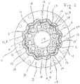
- Fig. 1 shows a multi-screw extruder with different housing areas 2; 3 of an extruder housing 4.
- a process chamber 5 is shown, which is delimited from the inner housing portion 2 via an insert 6, in particular an inliner.
- Supply channels 7, in particular cooling channels 8, extend in the inner housing region 2.
- Fig. 1 shows a cross section through the extruder housing 4 of a ring extruder 9, in which (not shown) extruder screws are arranged annularly around a core, also not shown around.
- the supply channels 7 extend in the housing portion 2 of the wall 11 of the ring extruder 9, which adjoins the insert 6 radially on the outside.
- the process space 5, which receives the annularly abutting extruder screws (not shown) of the ring extruder 9, is delimited from the other housing areas 2 by an insert 6, in particular an inliner.
- the insert 6 has a wall thickness 12 which in particular does not exceed a value of 5 mm, preferably a value of 4.2 mm and particularly preferably a value of 3.4 mm or 3 mm with an outer diameter of the screw of 71 mm.
- the insert 6 in the gusset regions 13 and in the regions 14 of the insert 6 extending between the gussets 13 each have a wall thickness 12 of less than 5 mm, less than 4.2 mm and particularly preferably 3.4 or 3 mm on the basis of FIG aforementioned screw outer diameter.
- the insert 6 lies with its outer contour 15 largely against the inner contour 16 of the housing portion 2 of the extruder housing 4, which adjoins the insert 6 radially on the outside.
- the outer contour 15 of the insert 6 is adapted to the inner contour 16 of the radially outer following housing portion 2.
- the insert 6 which surrounds the process space radially on the outside, lies flat against the inner contour 16 of that housing region 2; 3, which connects radially outward to the insert 6.
- cooling channels 8 are introduced, which cool or temper the extruder housing 4 and / or the process chamber 5.
- the outer contour of the insert and the inner contour of the extruder housing are formed rosette-shaped such that the respective gusset adjacent back portions of the insert in the case of rotation about its own axis can not rotate past the counter-configured part of the inner contour of the extruder housing.
- Fig. 2 shows a representation with a ring extruder 9, the extruder screws, not shown, which are arranged in a ring around a core, also not shown around.
- the extruder screws extend in a process space 5, which is bounded radially outwardly by an insert 6, in particular an inliner.
- the insert 6 off Fig. 2 It differs from the one in Fig. 1 insert 6 shown that the wall thickness 12 of the insert 6, in particular of the inliner in the region of the gusset 13 and the regions 14 extending between the gussets 13 assumes different values.
- the insert 6, in particular the inliner 6, for the transmission of torsional forces lies flat against the inner contour 16 of the respectively radially outwardly adjoining housing region 2.
- cooling channels 8 are used for purposeful cooling of the process spaces, in particular in the region of the gusset 13 and extending between the gussets areas 14 of the housing portion 2 of the extruder housing 4th
- housing portion 2 Radially outside the housing portion 2 is followed by a housing portion 3, which has screw holes, which serve to connect extruder housing parts 17.
Landscapes
- Engineering & Computer Science (AREA)
- Mechanical Engineering (AREA)
- Extrusion Moulding Of Plastics Or The Like (AREA)
- Processing And Handling Of Plastics And Other Materials For Molding In General (AREA)
Claims (14)
- Extrudeuse à plusieurs vis comportant un boîtier d'extrudeuse (4) qui présente un matériau support (11), dans lequel s'étend au moins un canal d'alimentation (7), qui entoure au moins une chambre de traitement (5) qui reçoit au moins deux vis d'extrudeuse, caractérisée en ce qu'entre le boîtier d'extrudeuse (4) et la chambre de traitement (5) est agencé un insert (6) dont, au moins par zones, l'épaisseur de paroi (12), ne dépasse pas 7 % par rapport au diamètre extérieur d'une vis d'extrudeuse.
- Extrudeuse à plusieurs vis selon la revendication 1, caractérisée en ce que, au moins par zones, l'épaisseur de paroi (12) de l'insert (6) ne dépasse pas 6 %.
- Extrudeuse à plusieurs vis selon la revendication 1, caractérisée en ce que, au moins par zones, l'épaisseur de paroi (12) de l'insert (6) ne dépasse pas 5 %.
- Extrudeuse à plusieurs vis selon la revendication 1, caractérisée en ce que, au moins par zones, l'épaisseur de paroi (12) de l'insert (6) ne dépasse pas 4,5 %.
- Extrudeuse à plusieurs vis selon l'une ou plusieurs des revendications précédentes, caractérisée en ce que l'insert (6) est réalisé par érosion au fil.
- Extrudeuse à plusieurs vis selon l'une ou plusieurs des revendications précédentes, caractérisée en ce que le boîtier d'extrudeuse (4) est réalisé par érosion au fil.
- Extrudeuse à plusieurs vis selon l'une ou plusieurs des revendications précédentes, caractérisée en ce que le contour extérieur (15) de l'insert (6) est adapté au contour intérieur (16) du boîtier d'extrudeuse (4).
- Extrudeuse à plusieurs vis selon l'une ou plusieurs des revendications précédentes, caractérisée en ce que l'insert (6) est agencé de manière bloquée en rotation par rapport au contour intérieur (16) du boîtier d'extrudeuse (4).
- Extrudeuse à plusieurs vis selon l'une ou plusieurs des revendications précédentes, caractérisée en ce que l'insert (6) transmet des forces de torsion des vis d'extrudeuse au boîtier d'extrudeuse (4).
- Extrudeuse à plusieurs vis selon l'une ou plusieurs des revendications précédentes, caractérisée en ce que pour la transmission de force et pour le soutien sur la périphérie extérieure (15), l'insert (6) est en appui sur la périphérie intérieure (16) du boîtier d'extrudeuse (4).
- Extrudeuse à plusieurs vis selon la revendication 1, caractérisée en ce que le canal d'alimentation (7) est un canal de refroidissement (8) qui reçoit un agent de refroidissement pour refroidir la chambre de traitement (5).
- Extrudeuse à plusieurs vis selon l'une ou plusieurs des revendications précédentes, caractérisée en ce que l'extrudeuse est une extrudeuse à anneaux (9).
- Extrudeuse à plusieurs vis selon l'une ou plusieurs des revendications précédentes, caractérisée en ce que le boîtier d'extrudeuse (4) est constitué par au moins deux parties (17) de boîtier d'extrudeuse reliées l'une à l'autre.
- Insert destiné à être agencé dans un boîtier d'extrudeuse (4) d'une extrudeuse à plusieurs vis selon la revendication 1, le boîtier d'extrudeuse présentant un matériau support (11), dans lequel s'étend au moins un canal d'alimentation (7), qui entoure au moins une chambre de traitement (5) qui reçoit au moins deux vis d'extrudeuse, l'insert (6) étant agencé entre le boîtier d'extrudeuse (4) et la chambre de traitement (5), caractérisé en ce que l'insert présente, au moins par zones, une épaisseur de paroi (12) qui ne dépasse par 7% par rapport au diamètre extérieur d'une vis d'extrudeuse.
Priority Applications (1)
| Application Number | Priority Date | Filing Date | Title |
|---|---|---|---|
| PL15162505T PL2933080T3 (pl) | 2014-04-04 | 2015-04-02 | Wieloślimakowa wytłaczarka z wymienną wkładką chroniącą cylinder przed zużyciem ściernym |
Applications Claiming Priority (1)
| Application Number | Priority Date | Filing Date | Title |
|---|---|---|---|
| DE202014002902.4U DE202014002902U1 (de) | 2014-04-04 | 2014-04-04 | Mehrwellenextruder mit einem Extrudergehäuse |
Publications (2)
| Publication Number | Publication Date |
|---|---|
| EP2933080A1 EP2933080A1 (fr) | 2015-10-21 |
| EP2933080B1 true EP2933080B1 (fr) | 2018-09-19 |
Family
ID=50726448
Family Applications (1)
| Application Number | Title | Priority Date | Filing Date |
|---|---|---|---|
| EP15162505.0A Active EP2933080B1 (fr) | 2014-04-04 | 2015-04-02 | Extrudeuse a plusieurs arbres avec une partie rapportee d'usure remplacable ("inliner") |
Country Status (4)
| Country | Link |
|---|---|
| EP (1) | EP2933080B1 (fr) |
| DE (1) | DE202014002902U1 (fr) |
| HU (1) | HUE041293T2 (fr) |
| PL (1) | PL2933080T3 (fr) |
Families Citing this family (5)
| Publication number | Priority date | Publication date | Assignee | Title |
|---|---|---|---|---|
| DE202015104765U1 (de) | 2015-09-08 | 2016-01-12 | Blach Verwaltungs GmbH + Co. KG | Anlage zur kontinuierlichen Aufbereitung von Gummimassen mit Fasspresse |
| DE202015106285U1 (de) | 2015-11-18 | 2016-01-11 | Blach Verwaltungs Gmbh & Co. Kg | RingExtruder zur kontinuierlichen Aufbereitung von Gummimassen mit Co-Extruder und Kühlsystem |
| DE102015120586B4 (de) | 2015-09-08 | 2018-10-18 | Blach Verwaltungs Gmbh & Co. Kg | Ringextruder zur kontinuierlichen Aufbereitung von Gummimaterial mit Co-Extruder, Anlage und Verfahren zur Vorverarbeitung eines kontinuierlich aufzubereitenden Gummimaterials |
| DE202015104764U1 (de) | 2015-09-08 | 2016-01-12 | Blach Verwaltungs GmbH + Co. KG | RingExtruder zur kontinuierlichen Aufbereitung von Gummimassen mit Co-Extruder |
| DE102017123940A1 (de) | 2016-10-14 | 2018-05-09 | Blach Verwaltungs GmbH + Co. KG | Augmented-Reality bei Extruderanlage |
Citations (1)
| Publication number | Priority date | Publication date | Assignee | Title |
|---|---|---|---|---|
| DE2423785B1 (de) * | 1974-05-16 | 1975-09-11 | Werner & Pfleiderer, 7000 Stuttgart | Verschleißeinsatz für das Schneckengehäuse einer Doppelschneckenstrangpresse oder -spritzgießmaschine |
Family Cites Families (8)
| Publication number | Priority date | Publication date | Assignee | Title |
|---|---|---|---|---|
| DE7244106U (de) * | 1974-05-16 | Hermann Berstorff Maschinenbau Gmbh | Buchse für ein Doppelschnecken-Gehäuse eines Kunststoff- oder Gummi- Extruders | |
| LU48131A1 (fr) * | 1964-03-28 | 1965-05-05 | ||
| DE2256671C2 (de) * | 1972-11-18 | 1973-12-20 | Werner & Pfleiderer, 7000 Stuttgart | Verfahren zum verschleißfesten Auskleiden von Extrudergehäusebohrungen und nach diesem Verfahren hergestellte Verschleißschutzauskleidung |
| DE2558611C3 (de) * | 1975-12-24 | 1982-09-23 | Werner & Pfleiderer, 7000 Stuttgart | Verfahren zum verschleißfesten Auskleiden des Arbeitsraumes von Schneckenextrudern |
| DE3010659C2 (de) * | 1980-03-20 | 1988-06-16 | Fa. Friedrich Theysohn, 3012 Langenhagen | Doppelschneckenextruder mit Verschleißeinsatz |
| JPS62231719A (ja) | 1986-04-01 | 1987-10-12 | Kobe Kikai Kk | ゴム材料の押出装置 |
| DE10317357B4 (de) * | 2003-04-15 | 2006-10-26 | 3+Extruder Gmbh | Extruder |
| DE102007016346A1 (de) * | 2007-04-03 | 2008-10-09 | Blach Verwaltungs Gmbh & Co. Kg | Mehrwellenextrudervorrichtung und Verfahren zum Betreiben derselben |
-
2014
- 2014-04-04 DE DE202014002902.4U patent/DE202014002902U1/de not_active Expired - Lifetime
-
2015
- 2015-04-02 HU HUE15162505A patent/HUE041293T2/hu unknown
- 2015-04-02 PL PL15162505T patent/PL2933080T3/pl unknown
- 2015-04-02 EP EP15162505.0A patent/EP2933080B1/fr active Active
Patent Citations (1)
| Publication number | Priority date | Publication date | Assignee | Title |
|---|---|---|---|---|
| DE2423785B1 (de) * | 1974-05-16 | 1975-09-11 | Werner & Pfleiderer, 7000 Stuttgart | Verschleißeinsatz für das Schneckengehäuse einer Doppelschneckenstrangpresse oder -spritzgießmaschine |
Also Published As
| Publication number | Publication date |
|---|---|
| PL2933080T3 (pl) | 2019-04-30 |
| HUE041293T2 (hu) | 2019-05-28 |
| DE202014002902U1 (de) | 2014-04-29 |
| EP2933080A1 (fr) | 2015-10-21 |
Similar Documents
| Publication | Publication Date | Title |
|---|---|---|
| EP2933080B1 (fr) | Extrudeuse a plusieurs arbres avec une partie rapportee d'usure remplacable ("inliner") | |
| DE102010026535B4 (de) | Planetwalzenextrudermodul mit segmentiertem Gehäuse | |
| EP2952275B1 (fr) | Élément hélicoïdaux et procédé de fabrication additive d'éléments hélicoïdaux | |
| EP1620246B1 (fr) | Extrudeur a arbres multiples | |
| EP1533101B2 (fr) | Extrudeuse à vis planétaires pour la préparation et l'extrusion de masses plastiques | |
| DE102016007290A1 (de) | Starter für das Devulkanisieren von Altgummi | |
| EP2032331B1 (fr) | Extrudeuse à vis avec un dispositif de refroidissement dans la zone d'alimentation | |
| CH618893A5 (fr) | ||
| EP0062203B1 (fr) | Douille d'entrée pour extrudeurs avec une vis sans fin | |
| DE102013000708A1 (de) | Verfahren zur Extrusion von Kunststoffen, die zum Kleben neigen | |
| DE2256671B1 (de) | Verfahren zum verschleissfesten auskleiden von extrudergehaeusebohrungen und nach diesem verfahren hergestellte verschleisschutzauskleidung | |
| DE102009013839A1 (de) | Planetenspindeln | |
| DE102004052055B4 (de) | Extruder | |
| DE102017006638A1 (de) | Füllteilmodul in Planetwalzenextruderbauweise | |
| DE102007058174B4 (de) | Extruder | |
| EP4247613B1 (fr) | Élément de palier de support pour une vis d'extrusion destinée à une extrudeuse multi-vis | |
| DE102009038280A1 (de) | Herstellung mit anorganischen Stoffen hoch gefüllter Kunststoffe | |
| DE102014004865B4 (de) | Mehrwellenextruder mit einem Extrudergehäuse und Einsatz zur Anordnung | |
| AT503395A2 (de) | Plastifizierzylinder | |
| DE69403704T2 (de) | Strangpresse | |
| DE102021214449B3 (de) | Doppelschneckenförderer | |
| EP2842716A1 (fr) | Machine à vis sans fin et procédé de préparation de matières plastiques en fusion | |
| AT505894A1 (de) | Granuliervorrichtung und granulierlochplatte | |
| EP2401134B1 (fr) | Extrudeuse-soudeuse manuelle comprenant une semelle de soudage monobloc en plastique | |
| EP3892441A1 (fr) | La mise à niveau d'une installation d'extrudeuse |
Legal Events
| Date | Code | Title | Description |
|---|---|---|---|
| PUAI | Public reference made under article 153(3) epc to a published international application that has entered the european phase |
Free format text: ORIGINAL CODE: 0009012 |
|
| AK | Designated contracting states |
Kind code of ref document: A1 Designated state(s): AL AT BE BG CH CY CZ DE DK EE ES FI FR GB GR HR HU IE IS IT LI LT LU LV MC MK MT NL NO PL PT RO RS SE SI SK SM TR |
|
| AX | Request for extension of the european patent |
Extension state: BA ME |
|
| 17P | Request for examination filed |
Effective date: 20160118 |
|
| RBV | Designated contracting states (corrected) |
Designated state(s): AL AT BE BG CH CY CZ DE DK EE ES FI FR GB GR HR HU IE IS IT LI LT LU LV MC MK MT NL NO PL PT RO RS SE SI SK SM TR |
|
| STAA | Information on the status of an ep patent application or granted ep patent |
Free format text: STATUS: EXAMINATION IS IN PROGRESS |
|
| 17Q | First examination report despatched |
Effective date: 20180201 |
|
| GRAP | Despatch of communication of intention to grant a patent |
Free format text: ORIGINAL CODE: EPIDOSNIGR1 |
|
| STAA | Information on the status of an ep patent application or granted ep patent |
Free format text: STATUS: GRANT OF PATENT IS INTENDED |
|
| RIC1 | Information provided on ipc code assigned before grant |
Ipc: B29C 47/08 20060101ALN20180411BHEP Ipc: B29C 47/42 20060101ALI20180411BHEP Ipc: B29B 7/82 20060101ALI20180411BHEP Ipc: B29C 47/66 20060101ALN20180411BHEP Ipc: B29B 7/84 20060101ALN20180411BHEP Ipc: B29B 7/48 20060101AFI20180411BHEP |
|
| RIC1 | Information provided on ipc code assigned before grant |
Ipc: B29B 7/84 20060101ALN20180417BHEP Ipc: B29C 47/42 20060101ALI20180417BHEP Ipc: B29C 47/08 20060101ALN20180417BHEP Ipc: B29B 7/48 20060101AFI20180417BHEP Ipc: B29B 7/82 20060101ALI20180417BHEP Ipc: B29C 47/66 20060101ALN20180417BHEP |
|
| INTG | Intention to grant announced |
Effective date: 20180503 |
|
| GRAS | Grant fee paid |
Free format text: ORIGINAL CODE: EPIDOSNIGR3 |
|
| GRAA | (expected) grant |
Free format text: ORIGINAL CODE: 0009210 |
|
| STAA | Information on the status of an ep patent application or granted ep patent |
Free format text: STATUS: THE PATENT HAS BEEN GRANTED |
|
| RBV | Designated contracting states (corrected) |
Designated state(s): AL AT BE BG CH CY CZ DK EE ES FI FR GB GR HR HU IE IS IT LI LT LU LV MC MK MT NL NO PL PT RO RS SE SI SK SM TR |
|
| REG | Reference to a national code |
Ref country code: DE Ref legal event code: R108 |
|
| AK | Designated contracting states |
Kind code of ref document: B1 Designated state(s): AL AT BE BG CH CY CZ DK EE ES FI FR GB GR HR HU IE IS IT LI LT LU LV MC MK MT NL NO PL PT RO RS SE SI SK SM TR |
|
| REG | Reference to a national code |
Ref country code: GB Ref legal event code: FG4D Free format text: NOT ENGLISH |
|
| REG | Reference to a national code |
Ref country code: CH Ref legal event code: EP |
|
| REG | Reference to a national code |
Ref country code: AT Ref legal event code: REF Ref document number: 1042724 Country of ref document: AT Kind code of ref document: T Effective date: 20181015 |
|
| REG | Reference to a national code |
Ref country code: IE Ref legal event code: FG4D Free format text: LANGUAGE OF EP DOCUMENT: GERMAN |
|
| REG | Reference to a national code |
Ref country code: RO Ref legal event code: EPE |
|
| REG | Reference to a national code |
Ref country code: NL Ref legal event code: MP Effective date: 20180919 |
|
| PG25 | Lapsed in a contracting state [announced via postgrant information from national office to epo] |
Ref country code: RS Free format text: LAPSE BECAUSE OF FAILURE TO SUBMIT A TRANSLATION OF THE DESCRIPTION OR TO PAY THE FEE WITHIN THE PRESCRIBED TIME-LIMIT Effective date: 20180919 Ref country code: BG Free format text: LAPSE BECAUSE OF FAILURE TO SUBMIT A TRANSLATION OF THE DESCRIPTION OR TO PAY THE FEE WITHIN THE PRESCRIBED TIME-LIMIT Effective date: 20181219 Ref country code: SE Free format text: LAPSE BECAUSE OF FAILURE TO SUBMIT A TRANSLATION OF THE DESCRIPTION OR TO PAY THE FEE WITHIN THE PRESCRIBED TIME-LIMIT Effective date: 20180919 Ref country code: NO Free format text: LAPSE BECAUSE OF FAILURE TO SUBMIT A TRANSLATION OF THE DESCRIPTION OR TO PAY THE FEE WITHIN THE PRESCRIBED TIME-LIMIT Effective date: 20181219 Ref country code: FI Free format text: LAPSE BECAUSE OF FAILURE TO SUBMIT A TRANSLATION OF THE DESCRIPTION OR TO PAY THE FEE WITHIN THE PRESCRIBED TIME-LIMIT Effective date: 20180919 Ref country code: LT Free format text: LAPSE BECAUSE OF FAILURE TO SUBMIT A TRANSLATION OF THE DESCRIPTION OR TO PAY THE FEE WITHIN THE PRESCRIBED TIME-LIMIT Effective date: 20180919 Ref country code: GR Free format text: LAPSE BECAUSE OF FAILURE TO SUBMIT A TRANSLATION OF THE DESCRIPTION OR TO PAY THE FEE WITHIN THE PRESCRIBED TIME-LIMIT Effective date: 20181220 |
|
| REG | Reference to a national code |
Ref country code: LT Ref legal event code: MG4D |
|
| PG25 | Lapsed in a contracting state [announced via postgrant information from national office to epo] |
Ref country code: LV Free format text: LAPSE BECAUSE OF FAILURE TO SUBMIT A TRANSLATION OF THE DESCRIPTION OR TO PAY THE FEE WITHIN THE PRESCRIBED TIME-LIMIT Effective date: 20180919 Ref country code: AL Free format text: LAPSE BECAUSE OF FAILURE TO SUBMIT A TRANSLATION OF THE DESCRIPTION OR TO PAY THE FEE WITHIN THE PRESCRIBED TIME-LIMIT Effective date: 20180919 Ref country code: HR Free format text: LAPSE BECAUSE OF FAILURE TO SUBMIT A TRANSLATION OF THE DESCRIPTION OR TO PAY THE FEE WITHIN THE PRESCRIBED TIME-LIMIT Effective date: 20180919 |
|
| PG25 | Lapsed in a contracting state [announced via postgrant information from national office to epo] |
Ref country code: CZ Free format text: LAPSE BECAUSE OF FAILURE TO SUBMIT A TRANSLATION OF THE DESCRIPTION OR TO PAY THE FEE WITHIN THE PRESCRIBED TIME-LIMIT Effective date: 20180919 Ref country code: NL Free format text: LAPSE BECAUSE OF FAILURE TO SUBMIT A TRANSLATION OF THE DESCRIPTION OR TO PAY THE FEE WITHIN THE PRESCRIBED TIME-LIMIT Effective date: 20180919 Ref country code: ES Free format text: LAPSE BECAUSE OF FAILURE TO SUBMIT A TRANSLATION OF THE DESCRIPTION OR TO PAY THE FEE WITHIN THE PRESCRIBED TIME-LIMIT Effective date: 20180919 Ref country code: IS Free format text: LAPSE BECAUSE OF FAILURE TO SUBMIT A TRANSLATION OF THE DESCRIPTION OR TO PAY THE FEE WITHIN THE PRESCRIBED TIME-LIMIT Effective date: 20190119 Ref country code: EE Free format text: LAPSE BECAUSE OF FAILURE TO SUBMIT A TRANSLATION OF THE DESCRIPTION OR TO PAY THE FEE WITHIN THE PRESCRIBED TIME-LIMIT Effective date: 20180919 |
|
| REG | Reference to a national code |
Ref country code: HU Ref legal event code: AG4A Ref document number: E041293 Country of ref document: HU |
|
| PG25 | Lapsed in a contracting state [announced via postgrant information from national office to epo] |
Ref country code: SK Free format text: LAPSE BECAUSE OF FAILURE TO SUBMIT A TRANSLATION OF THE DESCRIPTION OR TO PAY THE FEE WITHIN THE PRESCRIBED TIME-LIMIT Effective date: 20180919 Ref country code: SM Free format text: LAPSE BECAUSE OF FAILURE TO SUBMIT A TRANSLATION OF THE DESCRIPTION OR TO PAY THE FEE WITHIN THE PRESCRIBED TIME-LIMIT Effective date: 20180919 Ref country code: PT Free format text: LAPSE BECAUSE OF FAILURE TO SUBMIT A TRANSLATION OF THE DESCRIPTION OR TO PAY THE FEE WITHIN THE PRESCRIBED TIME-LIMIT Effective date: 20190119 |
|
| PLBE | No opposition filed within time limit |
Free format text: ORIGINAL CODE: 0009261 |
|
| STAA | Information on the status of an ep patent application or granted ep patent |
Free format text: STATUS: NO OPPOSITION FILED WITHIN TIME LIMIT |
|
| PG25 | Lapsed in a contracting state [announced via postgrant information from national office to epo] |
Ref country code: DK Free format text: LAPSE BECAUSE OF FAILURE TO SUBMIT A TRANSLATION OF THE DESCRIPTION OR TO PAY THE FEE WITHIN THE PRESCRIBED TIME-LIMIT Effective date: 20180919 |
|
| 26N | No opposition filed |
Effective date: 20190620 |
|
| PG25 | Lapsed in a contracting state [announced via postgrant information from national office to epo] |
Ref country code: SI Free format text: LAPSE BECAUSE OF FAILURE TO SUBMIT A TRANSLATION OF THE DESCRIPTION OR TO PAY THE FEE WITHIN THE PRESCRIBED TIME-LIMIT Effective date: 20180919 |
|
| REG | Reference to a national code |
Ref country code: CH Ref legal event code: PL |
|
| REG | Reference to a national code |
Ref country code: BE Ref legal event code: MM Effective date: 20190430 |
|
| PG25 | Lapsed in a contracting state [announced via postgrant information from national office to epo] |
Ref country code: LU Free format text: LAPSE BECAUSE OF NON-PAYMENT OF DUE FEES Effective date: 20190402 Ref country code: MC Free format text: LAPSE BECAUSE OF FAILURE TO SUBMIT A TRANSLATION OF THE DESCRIPTION OR TO PAY THE FEE WITHIN THE PRESCRIBED TIME-LIMIT Effective date: 20180919 |
|
| PG25 | Lapsed in a contracting state [announced via postgrant information from national office to epo] |
Ref country code: CH Free format text: LAPSE BECAUSE OF NON-PAYMENT OF DUE FEES Effective date: 20190430 Ref country code: LI Free format text: LAPSE BECAUSE OF NON-PAYMENT OF DUE FEES Effective date: 20190430 |
|
| PG25 | Lapsed in a contracting state [announced via postgrant information from national office to epo] |
Ref country code: BE Free format text: LAPSE BECAUSE OF NON-PAYMENT OF DUE FEES Effective date: 20190430 |
|
| PG25 | Lapsed in a contracting state [announced via postgrant information from national office to epo] |
Ref country code: TR Free format text: LAPSE BECAUSE OF FAILURE TO SUBMIT A TRANSLATION OF THE DESCRIPTION OR TO PAY THE FEE WITHIN THE PRESCRIBED TIME-LIMIT Effective date: 20180919 |
|
| PG25 | Lapsed in a contracting state [announced via postgrant information from national office to epo] |
Ref country code: IE Free format text: LAPSE BECAUSE OF NON-PAYMENT OF DUE FEES Effective date: 20190402 |
|
| PG25 | Lapsed in a contracting state [announced via postgrant information from national office to epo] |
Ref country code: CY Free format text: LAPSE BECAUSE OF FAILURE TO SUBMIT A TRANSLATION OF THE DESCRIPTION OR TO PAY THE FEE WITHIN THE PRESCRIBED TIME-LIMIT Effective date: 20180919 |
|
| REG | Reference to a national code |
Ref country code: AT Ref legal event code: MM01 Ref document number: 1042724 Country of ref document: AT Kind code of ref document: T Effective date: 20200402 |
|
| PG25 | Lapsed in a contracting state [announced via postgrant information from national office to epo] |
Ref country code: MT Free format text: LAPSE BECAUSE OF FAILURE TO SUBMIT A TRANSLATION OF THE DESCRIPTION OR TO PAY THE FEE WITHIN THE PRESCRIBED TIME-LIMIT Effective date: 20180919 |
|
| PG25 | Lapsed in a contracting state [announced via postgrant information from national office to epo] |
Ref country code: AT Free format text: LAPSE BECAUSE OF NON-PAYMENT OF DUE FEES Effective date: 20200402 |
|
| PG25 | Lapsed in a contracting state [announced via postgrant information from national office to epo] |
Ref country code: MK Free format text: LAPSE BECAUSE OF FAILURE TO SUBMIT A TRANSLATION OF THE DESCRIPTION OR TO PAY THE FEE WITHIN THE PRESCRIBED TIME-LIMIT Effective date: 20180919 |
|
| REG | Reference to a national code |
Ref country code: FR Ref legal event code: PLFP Year of fee payment: 9 |
|
| PGFP | Annual fee paid to national office [announced via postgrant information from national office to epo] |
Ref country code: PL Payment date: 20250328 Year of fee payment: 11 |
|
| PGFP | Annual fee paid to national office [announced via postgrant information from national office to epo] |
Ref country code: GB Payment date: 20250417 Year of fee payment: 11 |
|
| PGFP | Annual fee paid to national office [announced via postgrant information from national office to epo] |
Ref country code: HU Payment date: 20250430 Year of fee payment: 11 |
|
| PGFP | Annual fee paid to national office [announced via postgrant information from national office to epo] |
Ref country code: IT Payment date: 20250422 Year of fee payment: 11 |
|
| PGFP | Annual fee paid to national office [announced via postgrant information from national office to epo] |
Ref country code: FR Payment date: 20250425 Year of fee payment: 11 |
|
| PGFP | Annual fee paid to national office [announced via postgrant information from national office to epo] |
Ref country code: RO Payment date: 20250331 Year of fee payment: 11 |