EP2933111B1 - Dispositif d'impression par jet d'encre et dispositif d'alimentation en liquide - Google Patents
Dispositif d'impression par jet d'encre et dispositif d'alimentation en liquide Download PDFInfo
- Publication number
- EP2933111B1 EP2933111B1 EP13863799.6A EP13863799A EP2933111B1 EP 2933111 B1 EP2933111 B1 EP 2933111B1 EP 13863799 A EP13863799 A EP 13863799A EP 2933111 B1 EP2933111 B1 EP 2933111B1
- Authority
- EP
- European Patent Office
- Prior art keywords
- liquid
- pressure chamber
- pressure
- supplying
- ink
- Prior art date
- Legal status (The legal status is an assumption and is not a legal conclusion. Google has not performed a legal analysis and makes no representation as to the accuracy of the status listed.)
- Not-in-force
Links
- 239000007788 liquid Substances 0.000 title claims description 250
- 238000007641 inkjet printing Methods 0.000 title claims description 63
- 239000000463 material Substances 0.000 claims description 37
- 239000011347 resin Substances 0.000 claims description 37
- 229920005989 resin Polymers 0.000 claims description 37
- 238000006073 displacement reaction Methods 0.000 claims description 24
- 238000010586 diagram Methods 0.000 description 17
- 238000007639 printing Methods 0.000 description 11
- 230000004888 barrier function Effects 0.000 description 9
- 230000002950 deficient Effects 0.000 description 8
- 238000003756 stirring Methods 0.000 description 8
- -1 polypropylene Polymers 0.000 description 6
- 238000001514 detection method Methods 0.000 description 4
- 230000007423 decrease Effects 0.000 description 3
- 230000003247 decreasing effect Effects 0.000 description 3
- 238000007599 discharging Methods 0.000 description 3
- 230000000694 effects Effects 0.000 description 3
- 239000004698 Polyethylene Substances 0.000 description 2
- 239000004743 Polypropylene Substances 0.000 description 2
- 229910052782 aluminium Inorganic materials 0.000 description 2
- XAGFODPZIPBFFR-UHFFFAOYSA-N aluminium Chemical compound [Al] XAGFODPZIPBFFR-UHFFFAOYSA-N 0.000 description 2
- 229910052751 metal Inorganic materials 0.000 description 2
- 239000002184 metal Substances 0.000 description 2
- 229920000573 polyethylene Polymers 0.000 description 2
- 229920000139 polyethylene terephthalate Polymers 0.000 description 2
- 239000005020 polyethylene terephthalate Substances 0.000 description 2
- 229920001155 polypropylene Polymers 0.000 description 2
- 239000004677 Nylon Substances 0.000 description 1
- 239000004952 Polyamide Substances 0.000 description 1
- 230000004308 accommodation Effects 0.000 description 1
- 230000002596 correlated effect Effects 0.000 description 1
- 230000007547 defect Effects 0.000 description 1
- 230000008021 deposition Effects 0.000 description 1
- 239000011888 foil Substances 0.000 description 1
- 230000004048 modification Effects 0.000 description 1
- 238000012986 modification Methods 0.000 description 1
- 229920001778 nylon Polymers 0.000 description 1
- 238000005192 partition Methods 0.000 description 1
- 229920002647 polyamide Polymers 0.000 description 1
- 238000000638 solvent extraction Methods 0.000 description 1
- 230000000153 supplemental effect Effects 0.000 description 1
Images





Classifications
-
- B—PERFORMING OPERATIONS; TRANSPORTING
- B41—PRINTING; LINING MACHINES; TYPEWRITERS; STAMPS
- B41J—TYPEWRITERS; SELECTIVE PRINTING MECHANISMS, i.e. MECHANISMS PRINTING OTHERWISE THAN FROM A FORME; CORRECTION OF TYPOGRAPHICAL ERRORS
- B41J2/00—Typewriters or selective printing mechanisms characterised by the printing or marking process for which they are designed
- B41J2/005—Typewriters or selective printing mechanisms characterised by the printing or marking process for which they are designed characterised by bringing liquid or particles selectively into contact with a printing material
- B41J2/01—Ink jet
- B41J2/17—Ink jet characterised by ink handling
- B41J2/175—Ink supply systems ; Circuit parts therefor
- B41J2/17566—Ink level or ink residue control
-
- B—PERFORMING OPERATIONS; TRANSPORTING
- B41—PRINTING; LINING MACHINES; TYPEWRITERS; STAMPS
- B41J—TYPEWRITERS; SELECTIVE PRINTING MECHANISMS, i.e. MECHANISMS PRINTING OTHERWISE THAN FROM A FORME; CORRECTION OF TYPOGRAPHICAL ERRORS
- B41J2/00—Typewriters or selective printing mechanisms characterised by the printing or marking process for which they are designed
- B41J2/005—Typewriters or selective printing mechanisms characterised by the printing or marking process for which they are designed characterised by bringing liquid or particles selectively into contact with a printing material
- B41J2/01—Ink jet
- B41J2/17—Ink jet characterised by ink handling
- B41J2/175—Ink supply systems ; Circuit parts therefor
- B41J2/17503—Ink cartridges
- B41J2/17513—Inner structure
-
- B—PERFORMING OPERATIONS; TRANSPORTING
- B41—PRINTING; LINING MACHINES; TYPEWRITERS; STAMPS
- B41J—TYPEWRITERS; SELECTIVE PRINTING MECHANISMS, i.e. MECHANISMS PRINTING OTHERWISE THAN FROM A FORME; CORRECTION OF TYPOGRAPHICAL ERRORS
- B41J2/00—Typewriters or selective printing mechanisms characterised by the printing or marking process for which they are designed
- B41J2/005—Typewriters or selective printing mechanisms characterised by the printing or marking process for which they are designed characterised by bringing liquid or particles selectively into contact with a printing material
- B41J2/01—Ink jet
- B41J2/17—Ink jet characterised by ink handling
- B41J2/175—Ink supply systems ; Circuit parts therefor
- B41J2/17503—Ink cartridges
- B41J2/17556—Means for regulating the pressure in the cartridge
-
- B—PERFORMING OPERATIONS; TRANSPORTING
- B41—PRINTING; LINING MACHINES; TYPEWRITERS; STAMPS
- B41J—TYPEWRITERS; SELECTIVE PRINTING MECHANISMS, i.e. MECHANISMS PRINTING OTHERWISE THAN FROM A FORME; CORRECTION OF TYPOGRAPHICAL ERRORS
- B41J2/00—Typewriters or selective printing mechanisms characterised by the printing or marking process for which they are designed
- B41J2/005—Typewriters or selective printing mechanisms characterised by the printing or marking process for which they are designed characterised by bringing liquid or particles selectively into contact with a printing material
- B41J2/01—Ink jet
- B41J2/17—Ink jet characterised by ink handling
- B41J2/175—Ink supply systems ; Circuit parts therefor
- B41J2/17596—Ink pumps, ink valves
-
- B—PERFORMING OPERATIONS; TRANSPORTING
- B41—PRINTING; LINING MACHINES; TYPEWRITERS; STAMPS
- B41J—TYPEWRITERS; SELECTIVE PRINTING MECHANISMS, i.e. MECHANISMS PRINTING OTHERWISE THAN FROM A FORME; CORRECTION OF TYPOGRAPHICAL ERRORS
- B41J2/00—Typewriters or selective printing mechanisms characterised by the printing or marking process for which they are designed
- B41J2/005—Typewriters or selective printing mechanisms characterised by the printing or marking process for which they are designed characterised by bringing liquid or particles selectively into contact with a printing material
- B41J2/01—Ink jet
- B41J2/17—Ink jet characterised by ink handling
- B41J2/175—Ink supply systems ; Circuit parts therefor
- B41J2/17503—Ink cartridges
- B41J2/17513—Inner structure
- B41J2002/17516—Inner structure comprising a collapsible ink holder, e.g. a flexible bag
-
- B—PERFORMING OPERATIONS; TRANSPORTING
- B41—PRINTING; LINING MACHINES; TYPEWRITERS; STAMPS
- B41J—TYPEWRITERS; SELECTIVE PRINTING MECHANISMS, i.e. MECHANISMS PRINTING OTHERWISE THAN FROM A FORME; CORRECTION OF TYPOGRAPHICAL ERRORS
- B41J2/00—Typewriters or selective printing mechanisms characterised by the printing or marking process for which they are designed
- B41J2/005—Typewriters or selective printing mechanisms characterised by the printing or marking process for which they are designed characterised by bringing liquid or particles selectively into contact with a printing material
- B41J2/01—Ink jet
- B41J2/17—Ink jet characterised by ink handling
- B41J2/175—Ink supply systems ; Circuit parts therefor
- B41J2/17566—Ink level or ink residue control
- B41J2002/17586—Ink level or ink residue control using ink bag deformation for ink level indication
Definitions
- the present invention relates to an inkjet printing deviceprinting device and a liquid supplying device.
- an inkjet printing deviceprinting device it is known to set a pressure in an ink passage within a liquid jetting head to a negative pressure so as to jet out liquid from the liquid jetting head.
- a liquid jetting device as described in Patent Document 1 can be exemplified.
- the liquid jetting device described in Patent Document 1 is provided with a valve unit that uses a flexible film member that is displaced based on the negative pressure generated accompanying a reduction of liquid in the pressure chamber, and controls a liquid supply to a pressure chamber from a liquid container body by opening and closing a supplying passage by the displacement of the film member.
- the flexible film member used in the liquid jetting device described in Patent Document 1 has a low gas barrier property (air tightness), and there has been a problem that ink could not be jetted out due to a cavitation (phenomenon in which air dissolved in the ink turns into bubbles, and the ink cannot be jetted out) being generated inside the liquid jetting head.
- the present invention has been made in view of the above problem, and its aim is to provide an inkjet printing device and a liquid supplying device having a superior gas barrier property in the ink supplying passagesupplying passage in the liquid jetting head.
- an inkjet printing device is characteristic in including a liquid supplying unit that supplies liquid to a liquid jetting head configured to discharge the liquid onto a medium
- the liquid supplying unit includes: a pressure chamber that is connected to a supplying passagesupplying passage connecting a liquid container storing liquid and the liquid jetting head, stores therein the liquid from the liquid container, and supplies the liquid to the liquid jetting head; a valve provided on the supplying passage between the liquid container and the pressure chamber so as to open and close the supplying passage; and a negative pressure generating unit that applies a biasing force in a direction along which a distance between opposing inner walls of the pressure chamber is increased, and the pressure chamber is a bag-shaped member that is formed of a resin material of which wall surface is displaced accompanying a change in a liquid amount stored inside.
- the liquid supplying unit supplies the liquid inside the liquid container to the liquid jetting head.
- the liquid container and the liquid jetting head are connected through the supplying passage.
- the supplying passage is connected to the pressure chamber for storing therein the liquid, and the valve provided between the liquid container and the pressure chamber opens and closes the supplying passage so that the liquid inside the liquid container is supplied to the pressure chamber.
- the pressure chamber is applied with the biasing force in the direction along which the distance between opposing inner walls is increased by the negative pressure generating unit.
- the pressure chamber is a bag-shaped member that is formed of the resin material, of which wall surface is displaced accompanying the change in the liquid amount stored inside. Further, the pressure chamber is warped so that the distance between the inner walls increases by the biasing force applied by the negative pressure generating unit. Due to this, the inside of the pressure chamber comes to be of the negative pressure, and the inside of the supplying passage connected to the pressure chamber comes to be of the negative pressure. Accordingly, the liquid is jetted out from the liquid jetting head by making the inside of the supplying passage for supplying the liquid to the liquid jetting head be at a negative pressure by the liquid supplying unit.
- the resin material that forms the pressure chamber has a superior gas barrier property; thus, in accordance with the inkjet printing device according to the present invention, the occurrence of the cavitation in the liquid jetting head is reduced, and a jetting performance of the liquid jetting head can be stabilized. Further, since the resin material that forms the pressure chamber is inexpensive, a low-cost inkjet printing device can be provided.
- the inkjet printing device preferably further includes: a pressure detecting unit that detects a pressure within the supplying passage; and a control unit that determines that a liquid amount inside the liquid container is less than a predetermined amount when the pressure within the supplying passage detected by the pressure detecting unit becomes less than a predetermined pressure.
- the pressure in the supplying passage for supplying the liquid to the liquid jetting head is detected by the pressure detecting unit. Then, the control unit detects the liquid amount inside the liquid container based on the pressure detected by the pressure detecting unit. That is, the control unit determines that the remaining amount of the liquid inside the liquid container has become less than the predetermined amount when the pressure detected by the pressure detecting unit becomes less than the predetermined pressure.
- the remaining amount of the liquid inside the liquid container can be detected by detecting the pressure of the liquid in the supplying passage. Accordingly, when the control unit has determined that the remaining amount of the liquid inside the liquid container has become less than the predetermined amount, switching may be performed so that the liquid may be supplied to the liquid jetting head from a spare liquid container, or replacement of the liquid container may be notified to a user so that an occurrence of a defective printing caused by a run-out of ink can be prevented, even during a time-consuming and continuous printing.
- the pressure detecting unit includes a capacity detector that detects a displacement of the wall surface of the pressure chamber, and detects the pressure within the supplying passage by detecting the displacement of the wall surface of the pressure chamber detected by the capacity detector.
- the pressure detecting unit detects the pressure inside the supplying passage by detecting the displacement of the wall surface of the pressure chamber by the capacity detector. Accordingly, the liquid remaining amount can be grasped in advance by the control unit detecting the remaining amount of the liquid inside the liquid container based on the pressure inside the supplying passage detected by the pressure detecting unit, whereby the occurrence of the defective printing caused by the run-out of ink can be prevented.
- the pressure detecting unit includes: an intermediate pack that is provided within the supplying passage, and stores therein the liquid from the liquid container; and a capacity detector that detects a displacement of a wall surface of the intermediate pack, the intermediate pack is a bag-shaped member that is formed of a resin material of which wall surface is displaced accompanying a change in a liquid amount stored inside, and the pressure detecting unit detects the pressure within the supplying passage by detecting the displacement of the wall surface of the intermediate pack by the capacity detector.
- the pressure detecting unit detects the displacement of the wall surface of the intermediate pack by the capacity detector, and detects the pressure within the supplying passage for supplying the liquid to the liquid jetting head based on the detected displaced amount of the wall surface.
- the intermediate pack provided in the supplying passage is a bag-shaped member that is formed of the resin material, of which wall surface is displaced accompanying the change in the liquid amount stored inside.
- the pressure detecting unit detects the pressure inside the supplying passage by detecting the displacement of the wall surface of the intermediate pack by the capacity detector. Accordingly, the liquid remaining amount can be grasped in advance by the control unit detecting the remaining amount of the liquid inside the liquid container based on the pressure inside the supplying passage detected by the pressure detecting unit, whereby the occurrence of the defective printing caused by the run-out of ink can be prevented.
- the liquid supplying unit further includes a casing having a higher rigidity than the pressure chamber, and a part of the pressure chamber adheres to the inside of the casing.
- the pressure chamber being the bag-shaped member formed of the flexible resin material is provided within the device by adhering to the inside of the casing with the higher rigidity than the pressure chamber, whereby the liquid supplying unit can be provided at a desired position in a desired direction within the device. Accordingly, by providing the pressure chamber housed in such a casing in a state where its liquid supplying direction is vertically upright along a side wall of the device, space can be saved and a plurality of liquid supplying units can be provided in a limited space.
- the pressure chamber is provided therein with a plate-shaped member having a higher rigidity than the resin material.
- the pressure chamber can be prevented from being deformed in an unexpected direction, for example, a detection error can be prevented from occurring in the case of detecting the displacement of the wall surface of the pressure chamber. Further, in the case where the liquid supplying unit is mounted in the carriage of the liquid jetting head, the liquid in the pressure chamber can be prevented from suddenly moving even if a force of inertia is generated by the scanning movement of the carriage. Due to this, the occurrence of the cavitation by the scanning movement of the carriage and the pressure fluctuation within the pressure chamber can be reduced.
- a liquid supplying device is a liquid supplying device that supplies liquid to a liquid jetting head configured to discharge the liquid onto a medium, and is characteristic in including: a pressure chamber that is connected to a supplying passage connecting a liquid container storing liquid and the liquid jetting head, stores therein the liquid from the liquid container, and supplies the liquid to the liquid jetting head; a valve provided on the supplying passage between the liquid container and the pressure chamber so as to open and close the supplying passage; and a negative pressure generating unit that applies a biasing force in a direction along which a distance between opposing inner walls of the pressure chamber is increased, wherein the pressure chamber is a bag-shaped member that is formed of a resin material of which wall surface is displaced accompanying a change in a liquid amount stored inside.
- the present invention causes liquid to be discharged from the liquid jetting head by making the inside of the supplying passage for supplying the liquid to the liquid jetting head be at a negative pressure by the pressure chamber formed of the resin material with the superior gas barrier property, so the occurrence of the cavitation in the liquid jetting head is reduced, and a discharging property of the liquid jetting head can be stabilized.
- FIGS. 1 to 8 embodiments of the present invention will be described with reference to FIGS. 1 to 8 .
- an inkjet printing device 100 includes an ink supplying unit (liquid supplying unit) 10 that supplies ink in a liquid container 20 to an inkjet head (liquid jetting head) 22 that discharges ink (liquid) onto a recording medium (medium).
- FIG. 2 is a schematic diagram explaining an ink supplying passage in the inkjet printing device according to one embodiment of the present invention.
- the liquid container 20 and the ink supplying unit 10, as well as the ink supplying unit 10 and the inkjet head 22 are respectively connected by a supplying passage 21.
- the ink supplying unit 10 may be provided separately from the inkjet head 22 as shown in FIG. 2 , or may be on-carriage by being provided within a carriage of the inkjet head 22.
- the liquid container 20 is a container for storing the ink to be discharged by the inkjet head 22.
- the ink in the liquid container 20 is supplied to the ink supplying unit 10 and the inkjet head 22 through the supplying passage 21.
- the liquid container 20 has a gas barrier property, and the liquid container 20 and the supplying passage 21 are preferably connected by a joint member and the like that can prevent entrance of gas.
- the liquid container 20 is preferably a container formed of a material having a superior gas barrier property, and for example, it may be a resin-made ink pack and an ink tank, and the like. Further, the liquid container 20 may be a large-capacity container that can be used for an industrial inkjet printing device of which continued operation is expected.
- a plurality of liquid containers 20 may be provided as spare liquid containers, and when one liquid container 20 runs out of ink, the ink may be supplied to the inkjet head 22 by switching to another liquid container 20.
- the supplying passage 21 connects between the liquid container 20 and the inkjet head 22 in the inkjet printing device 100, and configures a passage for supplying the ink to the inkjet head 22 from the liquid container 20.
- the supplying passage 21 causes the liquid container 20 and the ink supplying unit 10 to be communicated, and also causes the ink supplying unit 10 and the inkjet head 22 to be communicated.
- the supplying passage 21 is a pipe having a cavity therein for letting the ink pass through, and is preferably formed of a material with a superior gas barrier property. Further, it is preferable for the supplying passage 21 to have flexibility from a viewpoint of its easy accommodation in the inkjet printing device 100.
- the ink supplying unit 10 includes a pressure chamber 11, a valve 12, and a negative pressure generating unit 13.
- FIG. 1 is a schematic diagram showing an example of the ink supplying unit provided in the inkjet printing device according to one embodiment of the present invention.
- the pressure chamber 11 may be provided in a casing 14.
- the ink supplying unit 10 adjusts a pressure in the ink supplying passage configured of the liquid container 20, the supplying passage 21, and the inkjet head 22, so as to function as a damper for stably discharging the ink from the inkjet head 22 without causing any defects such as cavitation and the like.
- the ink supplying unit 10 includes a group of members for adjusting the pressure in the ink supplying passage such as the valve 12, it may be termed a bubble unit.
- the pressure chamber 11 is connected to the supplying passage 21 that connects the liquid container 20 and the inkjet head 22.
- the supplying passage 21 on an inkjet head 22 side is termed a supplying passage 21a
- the supplying passage 21 on a liquid container 20 side is termed a supplying passage 21b.
- the pressure chamber 11 stores the ink supplied from the liquid container 20 to the pressure chamber 11 through the supplying passage 21b therein, and supplies the same to the inkjet head 22 through the supplying passage 21a.
- the pressure chamber 11 is a bag-shaped member formed of a resin material of which wall surface is displaced in accordance with a change in a liquid amount stored therein. That is, the pressure chamber 11 is formed of the resin material having a flexibility by which the wall surface is displaced in accordance with the change in the liquid amount stored therein.
- This resin material may have a flexibility to become warped by a biasing force applied from the negative pressure generating unit 13, that is, it may be of a resin material that deforms by the pressure chamber 11 being warped when the biasing force is applied from the negative pressure generating unit.
- the biasing force that the negative pressure generating unit 13 applies to the pressure chamber 11 may for example be a force by which the pressure inside the pressure chamber 11 becomes -0.5 kPa or more and -3.0 kPa or less with respect to atmospheric pressure.
- the resin material forming the pressure chamber 11 for example, polypropylene, polyethylene, polyethylene terephthalate, nylon, polyamide and the like may be exemplified, and it may have a multilayer structure in which an aluminum foil or an aluminum deposition layer is provided on such a resin material as needed.
- the pressure chamber 11 may be an ink pack that is formed of such a resin material. Due to being formed of such a resin material, the pressure chamber 11 has a superior gas barrier property, and in addition it can be obtained at a low cost.
- the pressure chamber 11 is formed such that a distance between the opposing inner walls is displaced in an approaching direction when the ink amount stored therein is decreased, and the distance between the inner walls is displaced in a separating direction when the ink amount stored therein is increased. That is, in the pressure chamber 11, an ink storing space expands or shrinks according to the ink amount stored therein.
- the pressure chamber 11 may house therein a stirring member 17 that stirs the ink stored therein.
- a stirring member 17 for example, a spherical member made of resin or metal may be exemplified.
- a plurality of stirring members 17 may be housed in the pressure chamber 11.
- the pressure chamber 11 may be provided therein with a plate-shaped member having higher rigidity than the resin material forming the pressure chamber 11.
- a plate-shaped member is not limited as to its size and how it is installed and the like, so long as it does not shut off a flow of the ink from the supplying passage 21b to the supplying passage 21a.
- the plate-shaped member may be provided so as to partition the inside of the pressure chamber 11 into a plurality of liquid chambers. Further, a hole may be provided in the plate-shaped member. Due to this, the rigidity of the pressure chamber 11 can be increased without obstructing the flow of the ink.
- the pressure chamber 11 can be prevented from being deformed in an unexpected direction by providing the plate-shaped member with high rigidity inside the pressure chamber 11, for example, a detection error can be prevented from occurring in a case of detecting a displacement of the wall surface of the pressure chamber 11. Even if force of inertia is generated by the scanning movement of the carriage in a case of having installed the ink supplying unit 10 in the carriage of the inkjet head 22, the liquid inside the pressure chamber 11 can be prevented from suddenly moving. Due to this, the generation of cavitation caused by the scanning movement of the carriage and the pressure fluctuation within the pressure chamber 11 can be reduced. Further, by providing the plate-shaped member with high rigidity inside the pressure chamber 11, the pressure chamber 11 is prevented from deforming in an unexpected direction and a motion path of the stirring members 17 is prevented from being closed, whereby the motion path of the stirring members 17 can be ensured.
- a connection port to the supplying passage 21a on an inkjet head 22 side of the pressure chamber 11 is preferably provided above a liquid surface when the liquid of 5% or more and 50% or less of a capacity of the pressure chamber 11 is stored in the pressure chamber 11. Further, more preferably, the connection port to the supplying passage 21a on the inkjet head 22 side of the pressure chamber 11 is preferably provided above the liquid surface when the liquid of 15% or more and 40% or less of the capacity of the pressure chamber 11 is stored in the pressure chamber 11, and still more preferably provided above the liquid surface when the liquid of 25% or more and 40% or less of the capacity of the pressure chamber 11 is stored in the pressure chamber 11.
- connection port to the supplying passage 21a on the inkjet head 22 side of the pressure chamber 11 is provided on a higher portion side, so that even larger amount of ink can be stored in the pressure chamber 11. Due to this, for example, the displaced amount can sufficiently be detected in a case of detecting the displaced amount of the wall surface of the pressure chamber 11, whereby detection accuracy can be improved.
- the pressure chamber 11 preferably has its longitudinal direction parallel to a gravitational direction. Accordingly, the influence of a force of inertia by a carriage operation can be reduced by providing the pressure chamber 11 vertically. Further, in the pressure chamber 11, the connection port to the supplying passage 21a on the inkjet head 22 side is preferably provided so as to guide the ink out in a direction vertical to a scanning movement direction of the carriage. Due to this, the pressure fluctuation in the ink to be supplied to the inkjet head 22 caused by the force of inertia generated by the scanning movement of the carriage can be prevented.
- the valve 12 is provided in the supplying passage 21b between the liquid container 20 and the pressure chamber 11, and it adjusts an amount of the ink flowing into the pressure chamber 11 from the liquid container 20 by opening and closing the supplying passage 21b.
- the valve 12 can be configured of a well-known diaphragm valve.
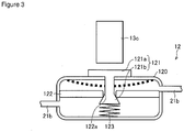
- FIG. 3 is a schematic diagram showing an example of the valve provided in the ink supply 10 shown in FIG. 1 .
- the valve body 121 is configured of an outer-side portion 121a positioned on the outside of the liquid chamber 120, and an inner-side portion 121b positioned on the inside of the liquid chamber 120.
- the inside of the liquid chamber 120 is partitioned into a liquid chamber of a liquid container 20 side and a liquid chamber of a pressure chamber 11 side by a partitioning plate 122 having an inter-liquid chamber passage 122a.
- the inner-side portion 121b of the valve body 121 is provided so as to penetrate through the inter-liquid chamber passage 122a.
- the inner-side portion 121b of the valve body 121 is connected to a spring 123 connected to an inner wall of the liquid chamber 120 on the pressure chamber 11 side, and is biased by the spring 123 in a direction along which the inter-liquid chamber passage 122a is closed.
- the valve 12 is configured such that liquid is supplied from the supplying passage 21b to the pressure chamber 11 with the inter-liquid chamber passage 122a being opened when the outer-side portion 121a is pressed by a contacting portion 13c of the negative pressure generating unit 13 to be described later. That is, when the contacting portion 13c presses the outer-side portion 121a, the outer-side portion 121a causes a side wall of the liquid chamber 120 to be displaced inwardly (displaced to a position shown by a dotted line in FIG. 3 ), the inner-side portion 121b moves in a direction along which the biasing force of the spring 123 is canceled, and the inter-liquid chamber passage 122a is opened. Due to this, the ink from the supplying passage 21b flows from the liquid chamber on the liquid container 20 side into the liquid chamber on the pressure chamber 11 side, and the ink amount inside the pressure chamber 11 is increased.
- the valve 12 Since the contacting portion 13c presses the outer-side portion 121a of the valve 12 when the ink amount inside the pressure chamber 11 becomes less than a predetermined amount, the valve 12 opens only when the ink amount in the pressure chamber 11 becomes less than the predetermined amount, and closes when the ink amount in the pressure chamber 11 is equal to the predetermined amount or more.
- the predetermined ink amount in the pressure chamber 11 can suitably be set according to a size of the pressure chamber, an ink droplet amount to be discharged from the inkjet head 22, and the like.
- the negative pressure generating unit 13 applies a biasing force in the direction along which the distance between opposing inner walls of the pressure chamber 11 is increased. Since the pressure chamber 11 is formed so as to be warped by the biasing force applied from the negative pressure generating unit 13, the negative pressure generating unit 13 applies this biasing force, so that the pressure chamber 11 is warped, whereby the inside of the pressure chamber 11 can be at a negative pressure.
- the negative pressure generating unit 13 adheres to the pressure chamber 11 in an adhering portion 13a, and causes the wall surface of the pressure chamber 11 on an adhering portion 13a side to be displaced in a direction separating away from its opposing inner wall, by being displaced by its own weight in a direction of separating away from the pressure chamber 11 with a fixed portion 13b as a fulcrum point.
- the negative pressure generating unit 13 is provided on a lower side along the gravitational direction than the pressure chamber 11.
- the negative pressure generating unit 13 causes the biasing force in the direction along which the distance between the opposing inner walls in the pressure chamber 11 is increased to be generated.
- the wall surface of the pressure chamber 11 on the adhering portion 13a side is displaced by being warped, and the inside of the pressure chamber 11 comes to be at a negative pressure.
- the inside of the supplying passage 21 connected to the pressure chamber 11 also comes to be at a negative pressure. Accordingly, with the negative pressure inside the pressure chamber 11 and the supplying passage 21 being maintained by the negative pressure generating unit 13, the ink discharge from the inkjet head 22 can be performed in a stable manner.
- the fixed portion 13b is fixed in the casing 14.
- the contacting portion 13c is attached to the negative pressure generating unit 13.
- the negative pressure generating unit 13 is displaced accompanying the displacement of the wall surfaces of the pressure chamber 11, the distance between the contacting portion 13c and the valve 12 becomes shorter, and the contacting portion 13c makes contact with the valve 12.
- the valve 12 opens the ink flowing passage by being pressed by the contacting portion 13c, and the ink flows into the pressure chamber 11. Accordingly, when the ink is sufficiently stored in the pressure chamber 11, the pressure inside the pressure chamber 11 is maintained by the valve 12 being closed, and when the ink within the pressure chamber 11 decreases, the valve 12 is opened and the ink in the pressure chamber 11 is replenished.
- the casing 14 is for housing the pressure chamber 11.
- the casing 14 has a structure having a higher rigidity than the pressure chamber 11.
- metal, resin and the like may be exemplified, however, light-weight and inexpensive resin may suitably be used.
- polypropylene, polyethylene, polyethylene terephthalate and the like may be used.
- the casing 14 adheres to a position opposing the adhering portion 13a of the pressure chamber in an adhering portion 14a. Due to this, the position of the pressure chamber 11 itself is not displaced by the displacement of the negative pressure generating unit 13, but is displaced so that the distance between the inner walls of the pressure chamber 11 increases.
- the ink supplying unit 10 can be provided at any desired position in the inkjet printing device 100 in a desired direction. Accordingly, by providing the pressure chamber 11 that is housed in such a casing 14 within the inkjet printing device 100 in a state where its ink supplying direction is vertically upright along a side wall of the device, space can be saved and it is also possible to provide a plurality of ink supplying units 10 within a limited space.
- the ink supplying unit 10 is mounted in the carriage of the inkjet head 22 by housing the pressure chamber 11 in the casing 14, the influence which the force of inertia generated by the scanning movement of the carriage imposes on the liquid inside the pressure chamber 11 can be reduced. Due to this, the generation of cavitation caused by the scanning movement of the carriage and the pressure fluctuation within the pressure chamber 11 can be reduced.
- an ink supplying unit 40 differs from the ink supplying unit 10 shown in FIG. 1 primarily in that a weight 15 and a spring 16 are attached to the negative pressure generating unit 13.
- FIG. 4 is a schematic diagram showing a reference example of the ink supplying unit provided in the inkjet printing device. Further, in FIG. 4 , components that are same as FIG. 1 are given the same reference numbers. Accordingly, as to the ink supplying unit 40, points differing from the ink supplying unit 10 will be described in detail, and detailed description for other points will be omitted.
- the weight 15 is provided on a surface that is opposite to a surface on an adhering portion 13a side at a position on an opposite side of the adhering portion 13a with the fixed portion 13b in between. Further, the spring 16 is provided at a position that opposes the weight 15 with the negative pressure generating unit 13 in between.
- the negative pressure generating unit 13 is positioned on an upper side than the pressure chamber 11 in the gravitational direction.
- a portion of the negative pressure generating unit 13 on a weight 15 side than the fixed portion 13b is displaced in a direction approaching the pressure chamber 11 by a load of the weight 15. Further, a force in the direction approaching the pressure chamber 11 by the load of the weight 15 is transmitted to the adhering portion 13a through the fixed portion 13b as a force in a direction separating away from the pressure chamber 11, and becomes a biasing force in a direction along which the distance between the inner walls of the pressure chamber 11 is increased. To adjust the force in the direction approaching the pressure chamber 11 by the weight 15, the spring 16 applies the force in the direction separating away from the pressure chamber 11 to the negative pressure generating unit 13 on the weight 15 side than the fixed portion 13b.
- the negative pressure generating unit 13 may have an end portion on an opposite side from where the weight 15 is provided to be protruded toward the pressure chamber 11 side. Due to this, when the displaced amount of the wall surface of the pressure chamber 11 is detected, the displaced amount can sufficiently be detected even in a case where the displaced amount of the wall surface of the pressure chamber 11 is small.
- the negative pressure generating unit 13 can be provided on the upper side in the gravitational direction than the pressure chamber 11 by providing the weight 15 and the spring 16 on the negative pressure generating unit 13.
- an ink supplying unit 50 differs from the ink supplying unit 10 shown in FIG. 1 primarily in a configuration of the negative pressure generating unit 13 and a positional relationship of the supplying passage 21 and the pressure chamber 11.
- FIG. 5 is a schematic diagram showing another example of the ink supplying unit provided in the inkjet printing device according to a reference example. Further, in FIG. 5 , components that are same as FIG. 1 are given the same reference numbers. Accordingly, as to the ink supplying unit 50, points differing from the ink supplying unit 10 will be described in detail, and detailed description for other points will be omitted.
- the negative pressure generating unit 13 is provided on a lower side in the gravitational direction than the pressure chamber 11. Further, the weight 15 is provided on a surface that is opposite to a surface on an adhering portion 13a side at a position on an opposite side of the fixed portion 13b with the adhering portion 13a in between. A portion of the negative pressure generating unit 13 closer to the weight 15 than the fixed portion 13b is displaced in the direction separating away from the pressure chamber 11 by the load of the weight 15.
- This force in the direction separating away from the pressure chamber 11 by the load of the weight 15 is transmitted to the adhering portion 13a as a force in a direction separating away from the pressure chamber 11, and becomes a biasing force in a direction along which the distance between the inner walls of the pressure chamber 11 is increased.
- connection port between the supplying passage 21a on the inkjet head 22 side and the pressure chamber 11 may be provided on a same side as the connection port between the supplying passage 21b on the liquid container 20 side and the pressure chamber 11. That is, the supplying passage 21a and the supplying passage 21b do not have to be provided with the pressure chamber 11 in between as shown in FIG. 1 .
- the connection port of the supplying passage 21a and the connection port of the supplying passage 21b may be provided on the same side of the pressure chamber 11, the supplying passage 21a may be bent in a direction of the inkjet head 22, and the supplying passage 21b may be bent in a direction of the liquid container 20.
- the weight 15 may be provided on the negative pressure generating unit 13 provided on the lower side in the gravitational direction than the pressure chamber 11, and may be provided on a same side as the connection port between the supplying passage 21b on the liquid container 20 side and the pressure chamber 11.
- FIG. 6 is a schematic diagram showing another example of the ink supplying unit provided in the inkjet printing device according to a reference example. Further, in FIG. 6 , components that are same as FIG. 1 are given the same reference numbers. Accordingly, as to the ink supplying unit 60, points differing from the ink supplying unit 10 will be described in detail, and detailed description for other points will be omitted.
- an extending direction of the supplying passage 21 is provided parallel to the gravitational direction. That is, a longitudinal direction of the pressure chamber 11 is provided parallel to the gravitational direction.
- the spring 16 is provided on a surface that is opposite to a surface on the adhering portion 13a side at a position on an opposite side of the adhering portion 13a with the fixed portion 13b in between. The spring 16 causes a portion of the negative pressure generating unit 13 on the spring 16 side to be displaced toward the pressure chamber 11 side.
- a force in a direction approaching the pressure chamber 11 by the spring 16 is transmitted to the adhering portion 13a through the fixed portion 13b as a force in a direction separating away from the pressure chamber 11, and becomes a biasing force in a direction along which a distance between inner walls of the pressure chamber 11 is increased.
- the pressure chamber 11 can suitably be maintained at a negative pressure, even if the longitudinal direction of the pressure chamber 11 is arranged in a vertical direction.
- an ink supplying unit 70 differs from the ink supplying unit 10 shown in FIG. 1 primarily in a configuration of the negative pressure generating unit 13.
- FIG. 7 is a schematic diagram showing another example of the ink supplying unit provided in the inkjet printing device according to a reference example. Further, in FIG. 7 , components that are same as FIG. 1 are given the same reference numbers. Accordingly, as to the ink supplying unit 70, points differing from the ink supplying unit 10 will be described in detail, and detailed description for other points will be omitted.
- an extending direction of the supplying passage 21 is provided parallel to the gravitational direction. That is, a longitudinal direction of the pressure chamber 11 is provided parallel to the gravitational direction.
- a joint unit 72 for joining a weight 71 is attached to a surface that is opposite to a surface on an adhering portion 13a side at a position on an opposite side of the adhering portion 13a with the fixed portion 13b in between.
- the joint unit 72 is for example configured of a rope attached to the weight 71 and pulleys, and causes the negative pressure generating unit 13 to be displaced in the direction separating away from the pressure chamber 11 by a load of the weight 71. Due to this, it causes a biasing force in the direction along which the distance between the inner walls of the pressure chamber 11 is increased is generated in the negative pressure generating unit 13.
- the inside of the pressure chamber 11 can suitably be maintained at a negative pressure, even if the longitudinal direction of the pressure chamber 11 is arranged in the vertical direction.
- an inkjet printing device 200 is provided with the ink supplying unit 10 that supplies the ink inside the liquid container 20 to the inkjet head 22 for discharging the ink onto a recording medium, and a pressure detector (pressure detecting unit) 23.
- FIG. 8 is a schematic diagram explaining an ink supplying passage in an inkjet printing device of another embodiment of the present invention.
- the inkjet printing device 200 is provided with a control unit (not shown).
- the inkjet printing device 200 differs from the inkjet printing device 100 shown in FIG. 2 in being provided with the pressure detector 23 and a control unit. Accordingly, as to the inkjet printing device 200, points differing from the inkjet printing device 100 will be described in detail, and detailed description for other points will be omitted.
- the pressure detector 23 detects a pressure in the supplying passage 21.
- the pressure detector 23 simply needs to be provided within the supplying passage 21, and as shown in FIG. 8 , it may be provided between the liquid container 20 and the ink supplying unit 10, or may be provided between the ink supplying unit 10 and the inkjet head 22.
- the pressure detector 23 is provided with an intermediate pack 24 and a capacity detector 25, and the pressure within the supplying passage 21 may be detected based on a displaced amount of a wall surface of the intermediate pack 24 detected by the capacity detector 25.
- the intermediate pack 24 is provided within the supplying passage 21, and stores therein the liquid from the liquid container 20.
- the intermediate pack 24 is a bag-shaped member formed of a resin material, of which wall surface is displaced in accordance with a change in a liquid amount stored therein.
- the intermediate pack 24 can be configured similarly to the pressure chamber 11.
- the intermediate pack 24 may be stored in a casing with higher rigidity than the intermediate pack 24.
- the intermediate pack 24 has its inside maintained at a negative pressure, and it is formed such that when the stored ink amount is decreased, it is displaced in a direction along which a distance between opposing inner walls decreases; and when the stored ink amount therein is increased, it is displaced in a direction along which the distance between the opposing inner walls increases.
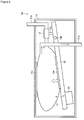
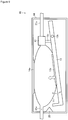
- the ink supplying unit 10 and the pressure detector 23 may be formed integrally by replacing the intermediate pack 24 by the pressure chamber 11 and making the pressure chamber 11 function as the intermediate pack 24. That is, as shown in FIG. 9 , the ink amount within the pressure chamber 11 is detected by providing a capacity detector 25 to be described later in the ink supplying unit 10 and making the capacity detector 25 detect the displacement of the wall surface of the pressure chamber 11. Further, the pressure detector 23 detects the pressure within the supplying passage 21 based on the displaced amount of the wall surface of the pressure chamber 11. As shown in FIG.
- the capacity detector 25 is provided on the wall surface of the ink supplying unit 10, and it simply needs to be provided such that the negative pressure generating unit 13 makes contact with the capacity detector 25 by the pressure chamber 11 shrinking when the ink amount within the pressure chamber 11 becomes less than a predetermined amount.
- the capacity detector 25 detects the displacement of the wall surface of the intermediate pack 24.
- the capacity detector 25 is provided within a casing in which the intermediate pack 24 is housed, and it detects the intermediate pack 24 expanding or shrinking its ink storage space in accordance with an amount of ink stored therein.
- the capacity detector 25 may for example be provided such that the negative pressure generating unit of the intermediate pack 24 makes contact with the capacity detector 25 by the intermediate pack 24 shrinking when the ink amount within the intermediate pack 24 becomes less than a predetermined amount.
- the capacity detector 25 detects the displaced amount of the wall surface of the intermediate pack.
- the displaced amount of the wall surface of the intermediate pack 24 and the pressure within the supplying passage 21 are in a correlated relationship, so that the pressure detector 23 detects the pressure within the supplying passage 21 based on the displaced amount of the wall surface of the intermediate pack 24 detected by the capacity detector 25.
- the control unit determines that the liquid amount within the liquid container 20 has become less than a predetermined amount when the pressure within the supplying passage 21 detected by the pressure detector 23 becomes less than the predetermined pressure.
- the control unit can be configured of a known calculating device such as a computer.
- control unit determines that the remaining amount of liquid within the liquid container 20 has become less than the predetermined amount
- switching may be performed so that the liquid may be supplied to the inkjet head 22 from a spare liquid container, or replacement of the liquid container 20 may be notified to a user so that the occurrence of a defective printing caused by the run-out of ink can be prevented, even during a time-consuming and continuous printing.
- a liquid supplying device is a liquid supplying device that supplies liquid to a liquid jetting head configured to discharge the liquid onto a medium, and is characteristic in including: a pressure chamber that is connected to a supplying passage connecting a liquid container storing liquid and the liquid jetting head, stores therein the liquid from the liquid container, and supplies the liquid to the liquid jetting head; a valve provided on the supplying passage between the liquid container and the pressure chamber so as to open and close the supplying passage; and a negative pressure generating unit that applies a biasing force in a direction along which a distance between opposing inner walls of the pressure chamber is increased, wherein the pressure chamber is a bag-shaped member that is formed of a resin material of which wall surface is displaced accompanying a change in a liquid amount stored inside.
- one embodiment of the liquid supplying device according to the present invention is the ink supplying unit 10 of the inkjet printing device 100 as aforementioned. Accordingly, one embodiment of the liquid supplying device according to the present invention is compliant with the description of the inkjet printing device according to the present invention as aforementioned.
- the inkjet printing device 100 includes the ink supplying unit 10 that supplies ink to the inkjet head 22 configured to discharge the ink onto a recording medium, wherein the ink supplying unit 10 includes: the pressure chamber 11 that is connected to the supplying passage 21 connecting the liquid container 20 storing the ink and the inkjet head 22, stores therein the ink from the liquid container 20, and supplies the ink to the inkjet head 22; the valve 12 provided on the supplying passage 21 between the liquid container 20 and the pressure chamber 11 so as to open and close the supplying passage 21; and the negative pressure generating unit 13 that applies a biasing force in the direction along which the distance between the opposing inner walls of the pressure chamber 11 is increased, and the pressure chamber 11 is a bag-shaped member that is formed of the resin material of which wall surface is displaced accompanying the change in a liquid amount stored inside.
- the ink supplying unit 10 supplies the ink in the liquid container 20 to the inkjet head 22.
- the liquid container 20 and the inkjet head 22 are connected through the supplying passage 21.
- the supplying passage 21 is connected to the pressure chamber 11 for storing therein the ink, and the valve 12 provided between the liquid container 20 and the pressure chamber opens and closes the supplying passage 21 so that the ink inside the liquid container 20 is supplied to the pressure chamber 11.
- the pressure chamber 11 is applied with the biasing force in the direction along which the distance between opposing inner walls is increased by the negative pressure generating unit 13.
- the pressure chamber 11 is a bag-shaped member that is formed of a resin material, of which wall surface is displaced accompanying the change in the liquid amount stored inside. Further, the pressure chamber 11 is warped so that the distance between the inner walls increases by the biasing force applied by the negative pressure generating unit 13. Due to this, the inside of the pressure chamber 11 comes to be at a negative pressure, and the inside of the supplying passage 21 connected to the pressure chamber 11 also comes to be at a negative pressure. Accordingly, the ink is jetted out from the inkjet head 22 by making the inside of the supplying passage for supplying the ink to the inkjet head 22 be at a negative pressure by the ink supplying unit 10.
- the resin material that forms the pressure chamber 11 has a superior gas barrier property; thus, according to the inkjet printing device 100, the occurrence of the cavitation in the inkjet head 22 can be reduced to stabilize a jetting performance of the inkjet head 22. Further, since the resin material that forms the pressure chamber 11 is inexpensive, a low-cost inkjet printing device 100 can be provided.
- the inkjet printing device 200 further includes the pressure detector 23 that detects a pressure within the supplying passage 21; and the control unit that determines that the ink amount inside the liquid container 20 is less than the predetermined amount when the pressure within the supplying passage 21 detected by the pressure detector 23 becomes less than a predetermined pressure.
- the control unit detects the ink amount inside the liquid container 20 based on the pressure detected by the pressure detector 23. That is, the control unit determines that the remaining amount of the ink inside the liquid container 20 has become less than the predetermined amount when the pressure detected by the pressure detector 23 becomes less than the predetermined pressure.
- the remaining amount of the ink inside the liquid container 20 can be detected by detecting the pressure in the ink supplying passage. Accordingly, when the control unit determines that the remaining amount of ink within the liquid container 20 has become less than the predetermined amount, switching may be performed so that the ink may be supplied to the inkjet head 22 from a spare liquid container, or replacement of the liquid container 20 may be notified to a user so that the occurrence of a defective printing caused by the run-out of ink can be prevented, even during a time-consuming and continuous printing.
- the pressure detector 23 includes the capacity detector 25 that detects the displacement of the wall surface of the pressure chamber 11, and detects the pressure within the supplying passage 21 by detecting the displacement of the wall surface of the pressure chamber 11 detected by the capacity detector 25.
- the pressure detector 23 detects the pressure inside the supplying passage 21 by detecting the displacement of the wall surface of the pressure chamber 11 by the capacity detector 25. Accordingly, the liquid remaining amount can be grasped in advance by the control unit detecting the remaining amount of the liquid inside the liquid container 20 based on the pressure inside the supplying passage 21 detected by the pressure detector 23, whereby the occurrence of the defective printing caused by the run-out of ink can be prevented.
- the pressure detector 23 includes: the intermediate pack 24 that is provided within the supplying passage 21, and stores therein the ink from the liquid container 20; and the capacity detector 25 that detects the displaced amount of the wall surface of the intermediate pack 24, the intermediate pack 24 is a bag-shaped member that is formed of the resin material, of which wall surface is displaced accompanying the change in the ink amount stored inside, and the pressure detector 23 detects the pressure within the supplying passage 21 by detecting the displacement of the wall surface of the intermediate pack 24 by the capacity detector 25.
- the pressure detector 23 detects the displaced amount of the wall surface of the intermediate pack 24 by the capacity detector 25, and detects the pressure within the supplying passage for supplying the ink to the inkjet head 22 based on the detected displaced amount of the wall surface.
- the intermediate pack 24 provided in the supplying passage 21 is a bag-shaped member that is formed of the resin material, of which wall surface is displaced accompanying the change in the ink amount stored inside.
- the pressure detector 23 detects the pressure inside the supplying passage 21 by detecting the displacement of the wall surface of the intermediate pack 24 by the capacity detector 25. Accordingly, the ink remaining amount can be grasped in advance by the control unit detecting the remaining amount of the ink inside the liquid container 20 based on the pressure inside the supplying passage 21 detected by the pressure detector 23, whereby the occurrence of the defective printing caused by the run-out of ink can be prevented.
- the ink supplying unit 10 further includes the casing 14 having the higher rigidity than the pressure chamber 11, and a part of the pressure chamber 11 adheres to the inside of the casing 14.
- the pressure chamber 11 being the bag-shaped member formed of the flexible resin material is provided within the device by adhering to the inside of the casing 14 with the higher rigidity than the pressure chamber 11, whereby the liquid supplying unit 10 can be provided at a desired position in a desired direction within the device. Accordingly, by providing the pressure chamber 11 housed in such a casing 14 in a state where its ink supplying direction is vertically upright along a side surface of the device, space can be saved and a plurality of liquid supplying units 10 can be provided in a limited space.
- the influence of the force of inertia generated by the scanning movement of the carriage applied to the ink within the pressure chamber 11 can be reduced, whereby the occurrence of the cavitation by the scanning movement of the carriage and the pressure fluctuation within the pressure chamber 11 can be reduced.
- the pressure chamber 11 is provided therein with a plate-shaped member having a higher rigidity than the resin material.
- the pressure chamber 11 can be prevented from being deformed in an unexpected direction, thus for example, a detection error can be prevented from occurring in the case of detecting the displacement of the wall surface of the pressure chamber 11. Further, even if force of inertia is generated by the scanning movement of the carriage in a case of having installed the ink supplying unit 10 in the carriage of the inkjet head 22, the ink inside the pressure chamber 11 can be prevented from suddenly moving. Due to this, the generation of cavitation caused by the scanning movement of the carriage and the pressure fluctuation within the pressure chamber 11 can be reduced.
- the ink supplying unit 10 is a liquid supplying unit that supplies ink to the inkjet head 22 configured to discharge the ink onto a recording medium, and is characteristic in including: the pressure chamber 11 that is connected to the supplying passage 21 connecting the liquid container 20 storing the ink and the inkjet head 22, stores therein the ink from the liquid container 20, and supplies the ink to the inkjet head 22; the valve 12 provided on the supplying passage 21 between the liquid container 20 and the pressure chamber 11 so as to open and close the supplying passage 21; and the negative pressure generating unit 13 that applies the biasing force in the direction along which the distance between the opposing inner walls of the pressure chamber 11 is increased, and the pressure chamber 11 is a bag-shaped member that is formed of a resin material, of which wall surface is displaced accompanying the change in a liquid amount stored inside.
- the present invention can be utilized in a liquid supplying device for an inkjet recording device.
Landscapes
- Ink Jet (AREA)
Claims (7)
- Dispositif d'impression à jet d'encre (100) comprenant :une unité d'alimentation de liquide (10) qui délivre un liquide à une tête d'éjection de liquide (22) configurée de manière à décharger le liquide sur un support,dans lequel l'unité d'alimentation de liquide comprend :un compartiment de pression (11) qui est relié à un passage d'alimentation reliant un conteneur de liquide stockant du liquide et la tête d'éjection de liquide, stocke le liquide à l'intérieur à partir du conteneur de liquide, et délivre le liquide à la tête d'éjection de liquide ;un boîtier (14) contenant le compartiment de pression (11) ;une vanne (12) agencée sur le passage d'alimentation entre le conteneur de liquide et le compartiment de pression afin d'ouvrir et de fermer le passage d'alimentation ; etune unité de production de dépression (13) qui produit un effort d'application suivant une direction dans laquelle une distance entre des parois internes opposées du compartiment de pression augmente, etle compartiment de pression est un élément en forme de poche qui est formé en un matériau à base de résine dont la surface de paroi est déplacée en accompagnant une variation de la quantité de liquide stockée à l'intérieur,caractérisé en ce que l'unité de production de dépression (13) comprend une partie fixe (13b) fixée sur le boîtier (14) et une partie adhérente (13a) collée sur le compartiment de pression (11), dans lequel l'unité de production de dépression (13) provoque le déplacement de la surface de paroi du compartiment de pression (11) d'un côté de partie adhérente (13a) dans une direction l'écartant de sa paroi interne opposée, en étant déplacée sous l'effet de son propre poids suivant une direction de séparation du compartiment de pression (11) avec une partie fixe (13b) en tant que point d'articulation.
- Dispositif d'impression à jet d'encre selon la revendication 1, comprenant, en outre :une unité de détection de pression (23) qui détecte une pression à l'intérieur du passage d'alimentation ; etune unité de commande qui détermine si une quantité de liquide à l'intérieur du conteneur de liquide est inférieure à une quantité prédéterminée lorsque la pression à l'intérieur du passage d'alimentation détectée par l'unité de détection de pression devient inférieure à une pression prédéterminée.
- Dispositif d'impression à jet d'encre selon la revendication 2, dans lequel l'unité de détection de pression comprend un détecteur de capacité qui détecte un déplacement de la surface de paroi du compartiment de pression, et détecte la pression à l'intérieur du passage d'alimentation qui est détectée en détectant le déplacement de la surface de paroi du compartiment de pression détecté par le détecteur de capacité.
- Dispositif d'impression à jet d'encre selon la revendication 2, dans lequel l'unité de détection de pression comprend :un bloc intermédiaire qui est agencé à l'intérieur du passage d'alimentation et stocke à l'intérieur le liquide à partir du conteneur liquide ; etun détecteur de capacité qui détecte un déplacement d'une surface de paroi du bloc intermédiaire,le bloc intermédiaire est un élément en forme de poche qui est formé en un matériau à base de résine, dont la surface de paroi est déplacée en accompagnant une variation sur une quantité de liquide stockée à l'intérieur, etl'unité de détection de pression détecte la pression à l'intérieur du passage d'alimentation en détectant le déplacement de la surface de paroi du bloc intermédiaire par le détecteur de capacité.
- Dispositif d'impression à jet d'encre selon la revendication 1, dans lequel l'unité d'alimentation de liquide comprend, en outre, un boîtier présentant une rigidité supérieure à celle du compartiment de pression, et
une partie du compartiment de pression adhère à la partie intérieure du boîtier. - Dispositif d'impression à jet d'encre selon l'une quelconque des revendications 1 à 5, dans lequel
le compartiment de pression comporte à l'intérieur un élément en forme de plaque présentant une rigidité supérieure à celle du matériau à base de résine. - Dispositif d'alimentation de liquide (10), selon l'une quelconque des revendications 1 à 6 destiné à délivrer un liquide d'alimentation à une tête d'éjection de liquide configurée de manière à décharger un liquide sur un support.
Applications Claiming Priority (2)
| Application Number | Priority Date | Filing Date | Title |
|---|---|---|---|
| JP2012275143A JP6166892B2 (ja) | 2012-12-17 | 2012-12-17 | インクジェット印刷装置及び液体供給装置 |
| PCT/JP2013/083589 WO2014098018A1 (fr) | 2012-12-17 | 2013-12-16 | Dispositif d'impression par jet d'encre et dispositif d'alimentation en liquide |
Publications (3)
| Publication Number | Publication Date |
|---|---|
| EP2933111A1 EP2933111A1 (fr) | 2015-10-21 |
| EP2933111A4 EP2933111A4 (fr) | 2017-02-01 |
| EP2933111B1 true EP2933111B1 (fr) | 2018-07-11 |
Family
ID=50978348
Family Applications (1)
| Application Number | Title | Priority Date | Filing Date |
|---|---|---|---|
| EP13863799.6A Not-in-force EP2933111B1 (fr) | 2012-12-17 | 2013-12-16 | Dispositif d'impression par jet d'encre et dispositif d'alimentation en liquide |
Country Status (5)
| Country | Link |
|---|---|
| US (1) | US9623668B2 (fr) |
| EP (1) | EP2933111B1 (fr) |
| JP (1) | JP6166892B2 (fr) |
| CN (1) | CN104884261B (fr) |
| WO (1) | WO2014098018A1 (fr) |
Families Citing this family (1)
| Publication number | Priority date | Publication date | Assignee | Title |
|---|---|---|---|---|
| CN112659756B (zh) * | 2020-12-16 | 2022-11-22 | 云侠科技(苏州)有限公司 | 一种打印机墨盒 |
Family Cites Families (14)
| Publication number | Priority date | Publication date | Assignee | Title |
|---|---|---|---|---|
| US6183076B1 (en) * | 1992-04-02 | 2001-02-06 | Hewlett-Packard Company | Printer having multi-chamber print cartridges and off-carriage regulator |
| JP2001162834A (ja) * | 1999-12-13 | 2001-06-19 | Canon Inc | インク供給装置およびインク供給方法 |
| JP2001353881A (ja) * | 2000-06-15 | 2001-12-25 | Canon Inc | 液体吐出記録装置および液体供給方法 |
| US6959984B2 (en) * | 2001-08-14 | 2005-11-01 | Canon Kabushiki Kaisha | Liquid container and inkjet cartridge |
| JP3606282B2 (ja) | 2001-11-12 | 2005-01-05 | セイコーエプソン株式会社 | 液体噴射装置 |
| JP2003159811A (ja) * | 2001-11-29 | 2003-06-03 | Seiko Epson Corp | インクジェット式記録装置 |
| US7185975B2 (en) * | 2003-03-11 | 2007-03-06 | Brother Kogyo Kabushiki Kaisha | Ink detecting apparatus and ink package |
| JP2006021380A (ja) * | 2004-07-07 | 2006-01-26 | Konica Minolta Medical & Graphic Inc | インクジェットプリンタ |
| JP4806616B2 (ja) * | 2006-09-29 | 2011-11-02 | 富士フイルム株式会社 | インクカートリッジ及びインクジェット記録装置 |
| WO2008102657A1 (fr) * | 2007-02-20 | 2008-08-28 | Seiko I Infotech Inc. | Système d'alimentation en liquide, imprimante à jet d'encre et procédé d'alimentation en liquide |
| TW200922799A (en) * | 2007-10-12 | 2009-06-01 | Toray Industries | Ink supplying apparatus for ink jet head, method of supplying ink, and manufacturing method of color filter |
| JP5159431B2 (ja) * | 2008-05-23 | 2013-03-06 | 株式会社セイコーアイ・インフォテック | インクカートリッジ及び記録装置 |
| JP5455755B2 (ja) * | 2009-06-08 | 2014-03-26 | 株式会社セイコーアイ・インフォテック | インクジェット記録装置 |
| JP5499989B2 (ja) * | 2010-03-12 | 2014-05-21 | 株式会社リコー | 画像形成装置 |
-
2012
- 2012-12-17 JP JP2012275143A patent/JP6166892B2/ja active Active
-
2013
- 2013-12-16 US US14/650,866 patent/US9623668B2/en not_active Expired - Fee Related
- 2013-12-16 EP EP13863799.6A patent/EP2933111B1/fr not_active Not-in-force
- 2013-12-16 CN CN201380065660.1A patent/CN104884261B/zh not_active Expired - Fee Related
- 2013-12-16 WO PCT/JP2013/083589 patent/WO2014098018A1/fr not_active Ceased
Non-Patent Citations (1)
| Title |
|---|
| None * |
Also Published As
| Publication number | Publication date |
|---|---|
| WO2014098018A1 (fr) | 2014-06-26 |
| JP2014117886A (ja) | 2014-06-30 |
| US9623668B2 (en) | 2017-04-18 |
| JP6166892B2 (ja) | 2017-07-19 |
| EP2933111A1 (fr) | 2015-10-21 |
| EP2933111A4 (fr) | 2017-02-01 |
| CN104884261A (zh) | 2015-09-02 |
| CN104884261B (zh) | 2017-03-08 |
| US20150328899A1 (en) | 2015-11-19 |
Similar Documents
| Publication | Publication Date | Title |
|---|---|---|
| JP4877028B2 (ja) | 液体収容容器 | |
| US6505923B1 (en) | Liquid supply system, liquid supply container and negative pressure generating member container used for the same system, and ink jet recording apparatus using the same system | |
| EP2371554B1 (fr) | Conteneur de liquides et dispositif de consommation de liquides | |
| US9669635B2 (en) | Attachment and attachment system | |
| JP4337894B2 (ja) | 流体収容容器 | |
| JP6125199B2 (ja) | インクジェットプリンター | |
| US9033478B2 (en) | Liquid accommodation body and accommodation body unit | |
| JP4985500B2 (ja) | 液体供給システム及びそのための製造方法 | |
| US20090244223A1 (en) | Liquid container and membrane valve | |
| JP2015193178A (ja) | 液体供給装置、及び液体吐出装置 | |
| US7185976B2 (en) | Liquid supply system and apparatus incorporating the same | |
| US8500262B2 (en) | Inkjet recording device | |
| EP2933111A1 (fr) | Dispositif d'impression par jet d'encre et dispositif d'alimentation en liquide | |
| JP4009821B2 (ja) | インク充填方法及びインクジェット式記録装置 | |
| JP5125164B2 (ja) | 流体収容容器 | |
| JP2012206455A (ja) | 液体供給装置およびこれを備えたインクジェット印刷装置 | |
| JP2008207390A (ja) | インクジェット用インク供給装置およびこれを備えるインクジェット装置 | |
| JP3136107U (ja) | インクジェットプリンタ | |
| JP6399156B2 (ja) | 液体貯留部および液体噴射装置 | |
| US20190389223A1 (en) | Reservoir and bubble structure | |
| JP5862019B2 (ja) | 液体容器 | |
| KR100784849B1 (ko) | 대용량 잉크 공급장치 | |
| JP4412004B2 (ja) | ヘッドカートリッジ及び液体吐出装置 | |
| KR20260030243A (ko) | 순환형 잉크 저장장치 및 이를 포함하는 잉크젯 프린터 | |
| JP2017061055A (ja) | ダンパー装置及びこれを備えた液体供給システム、並びにインクジェット式記録装置 |
Legal Events
| Date | Code | Title | Description |
|---|---|---|---|
| PUAI | Public reference made under article 153(3) epc to a published international application that has entered the european phase |
Free format text: ORIGINAL CODE: 0009012 |
|
| 17P | Request for examination filed |
Effective date: 20150717 |
|
| AK | Designated contracting states |
Kind code of ref document: A1 Designated state(s): AL AT BE BG CH CY CZ DE DK EE ES FI FR GB GR HR HU IE IS IT LI LT LU LV MC MK MT NL NO PL PT RO RS SE SI SK SM TR |
|
| AX | Request for extension of the european patent |
Extension state: BA ME |
|
| DAX | Request for extension of the european patent (deleted) | ||
| A4 | Supplementary search report drawn up and despatched |
Effective date: 20170105 |
|
| RIC1 | Information provided on ipc code assigned before grant |
Ipc: B41J 2/175 20060101AFI20161223BHEP |
|
| GRAP | Despatch of communication of intention to grant a patent |
Free format text: ORIGINAL CODE: EPIDOSNIGR1 |
|
| STAA | Information on the status of an ep patent application or granted ep patent |
Free format text: STATUS: GRANT OF PATENT IS INTENDED |
|
| INTG | Intention to grant announced |
Effective date: 20180202 |
|
| GRAS | Grant fee paid |
Free format text: ORIGINAL CODE: EPIDOSNIGR3 |
|
| GRAA | (expected) grant |
Free format text: ORIGINAL CODE: 0009210 |
|
| STAA | Information on the status of an ep patent application or granted ep patent |
Free format text: STATUS: THE PATENT HAS BEEN GRANTED |
|
| AK | Designated contracting states |
Kind code of ref document: B1 Designated state(s): AL AT BE BG CH CY CZ DE DK EE ES FI FR GB GR HR HU IE IS IT LI LT LU LV MC MK MT NL NO PL PT RO RS SE SI SK SM TR |
|
| REG | Reference to a national code |
Ref country code: GB Ref legal event code: FG4D |
|
| REG | Reference to a national code |
Ref country code: CH Ref legal event code: EP |
|
| REG | Reference to a national code |
Ref country code: AT Ref legal event code: REF Ref document number: 1016459 Country of ref document: AT Kind code of ref document: T Effective date: 20180715 |
|
| REG | Reference to a national code |
Ref country code: IE Ref legal event code: FG4D |
|
| REG | Reference to a national code |
Ref country code: DE Ref legal event code: R096 Ref document number: 602013040269 Country of ref document: DE |
|
| REG | Reference to a national code |
Ref country code: NL Ref legal event code: MP Effective date: 20180711 |
|
| REG | Reference to a national code |
Ref country code: LT Ref legal event code: MG4D |
|
| REG | Reference to a national code |
Ref country code: AT Ref legal event code: MK05 Ref document number: 1016459 Country of ref document: AT Kind code of ref document: T Effective date: 20180711 |
|
| PG25 | Lapsed in a contracting state [announced via postgrant information from national office to epo] |
Ref country code: NL Free format text: LAPSE BECAUSE OF FAILURE TO SUBMIT A TRANSLATION OF THE DESCRIPTION OR TO PAY THE FEE WITHIN THE PRESCRIBED TIME-LIMIT Effective date: 20180711 |
|
| PG25 | Lapsed in a contracting state [announced via postgrant information from national office to epo] |
Ref country code: LT Free format text: LAPSE BECAUSE OF FAILURE TO SUBMIT A TRANSLATION OF THE DESCRIPTION OR TO PAY THE FEE WITHIN THE PRESCRIBED TIME-LIMIT Effective date: 20180711 Ref country code: IS Free format text: LAPSE BECAUSE OF FAILURE TO SUBMIT A TRANSLATION OF THE DESCRIPTION OR TO PAY THE FEE WITHIN THE PRESCRIBED TIME-LIMIT Effective date: 20181111 Ref country code: PL Free format text: LAPSE BECAUSE OF FAILURE TO SUBMIT A TRANSLATION OF THE DESCRIPTION OR TO PAY THE FEE WITHIN THE PRESCRIBED TIME-LIMIT Effective date: 20180711 Ref country code: RS Free format text: LAPSE BECAUSE OF FAILURE TO SUBMIT A TRANSLATION OF THE DESCRIPTION OR TO PAY THE FEE WITHIN THE PRESCRIBED TIME-LIMIT Effective date: 20180711 Ref country code: GR Free format text: LAPSE BECAUSE OF FAILURE TO SUBMIT A TRANSLATION OF THE DESCRIPTION OR TO PAY THE FEE WITHIN THE PRESCRIBED TIME-LIMIT Effective date: 20181012 Ref country code: NO Free format text: LAPSE BECAUSE OF FAILURE TO SUBMIT A TRANSLATION OF THE DESCRIPTION OR TO PAY THE FEE WITHIN THE PRESCRIBED TIME-LIMIT Effective date: 20181011 Ref country code: BG Free format text: LAPSE BECAUSE OF FAILURE TO SUBMIT A TRANSLATION OF THE DESCRIPTION OR TO PAY THE FEE WITHIN THE PRESCRIBED TIME-LIMIT Effective date: 20181011 Ref country code: AT Free format text: LAPSE BECAUSE OF FAILURE TO SUBMIT A TRANSLATION OF THE DESCRIPTION OR TO PAY THE FEE WITHIN THE PRESCRIBED TIME-LIMIT Effective date: 20180711 Ref country code: FI Free format text: LAPSE BECAUSE OF FAILURE TO SUBMIT A TRANSLATION OF THE DESCRIPTION OR TO PAY THE FEE WITHIN THE PRESCRIBED TIME-LIMIT Effective date: 20180711 Ref country code: SE Free format text: LAPSE BECAUSE OF FAILURE TO SUBMIT A TRANSLATION OF THE DESCRIPTION OR TO PAY THE FEE WITHIN THE PRESCRIBED TIME-LIMIT Effective date: 20180711 |
|
| PG25 | Lapsed in a contracting state [announced via postgrant information from national office to epo] |
Ref country code: HR Free format text: LAPSE BECAUSE OF FAILURE TO SUBMIT A TRANSLATION OF THE DESCRIPTION OR TO PAY THE FEE WITHIN THE PRESCRIBED TIME-LIMIT Effective date: 20180711 Ref country code: LV Free format text: LAPSE BECAUSE OF FAILURE TO SUBMIT A TRANSLATION OF THE DESCRIPTION OR TO PAY THE FEE WITHIN THE PRESCRIBED TIME-LIMIT Effective date: 20180711 Ref country code: AL Free format text: LAPSE BECAUSE OF FAILURE TO SUBMIT A TRANSLATION OF THE DESCRIPTION OR TO PAY THE FEE WITHIN THE PRESCRIBED TIME-LIMIT Effective date: 20180711 Ref country code: ES Free format text: LAPSE BECAUSE OF FAILURE TO SUBMIT A TRANSLATION OF THE DESCRIPTION OR TO PAY THE FEE WITHIN THE PRESCRIBED TIME-LIMIT Effective date: 20180711 |
|
| REG | Reference to a national code |
Ref country code: DE Ref legal event code: R097 Ref document number: 602013040269 Country of ref document: DE |
|
| PG25 | Lapsed in a contracting state [announced via postgrant information from national office to epo] |
Ref country code: IT Free format text: LAPSE BECAUSE OF FAILURE TO SUBMIT A TRANSLATION OF THE DESCRIPTION OR TO PAY THE FEE WITHIN THE PRESCRIBED TIME-LIMIT Effective date: 20180711 Ref country code: CZ Free format text: LAPSE BECAUSE OF FAILURE TO SUBMIT A TRANSLATION OF THE DESCRIPTION OR TO PAY THE FEE WITHIN THE PRESCRIBED TIME-LIMIT Effective date: 20180711 Ref country code: EE Free format text: LAPSE BECAUSE OF FAILURE TO SUBMIT A TRANSLATION OF THE DESCRIPTION OR TO PAY THE FEE WITHIN THE PRESCRIBED TIME-LIMIT Effective date: 20180711 Ref country code: RO Free format text: LAPSE BECAUSE OF FAILURE TO SUBMIT A TRANSLATION OF THE DESCRIPTION OR TO PAY THE FEE WITHIN THE PRESCRIBED TIME-LIMIT Effective date: 20180711 |
|
| PLBE | No opposition filed within time limit |
Free format text: ORIGINAL CODE: 0009261 |
|
| STAA | Information on the status of an ep patent application or granted ep patent |
Free format text: STATUS: NO OPPOSITION FILED WITHIN TIME LIMIT |
|
| PG25 | Lapsed in a contracting state [announced via postgrant information from national office to epo] |
Ref country code: SM Free format text: LAPSE BECAUSE OF FAILURE TO SUBMIT A TRANSLATION OF THE DESCRIPTION OR TO PAY THE FEE WITHIN THE PRESCRIBED TIME-LIMIT Effective date: 20180711 Ref country code: DK Free format text: LAPSE BECAUSE OF FAILURE TO SUBMIT A TRANSLATION OF THE DESCRIPTION OR TO PAY THE FEE WITHIN THE PRESCRIBED TIME-LIMIT Effective date: 20180711 Ref country code: SK Free format text: LAPSE BECAUSE OF FAILURE TO SUBMIT A TRANSLATION OF THE DESCRIPTION OR TO PAY THE FEE WITHIN THE PRESCRIBED TIME-LIMIT Effective date: 20180711 |
|
| 26N | No opposition filed |
Effective date: 20190412 |
|
| REG | Reference to a national code |
Ref country code: DE Ref legal event code: R119 Ref document number: 602013040269 Country of ref document: DE |
|
| REG | Reference to a national code |
Ref country code: CH Ref legal event code: PL |
|
| GBPC | Gb: european patent ceased through non-payment of renewal fee |
Effective date: 20181216 |
|
| PG25 | Lapsed in a contracting state [announced via postgrant information from national office to epo] |
Ref country code: LU Free format text: LAPSE BECAUSE OF NON-PAYMENT OF DUE FEES Effective date: 20181216 Ref country code: MC Free format text: LAPSE BECAUSE OF FAILURE TO SUBMIT A TRANSLATION OF THE DESCRIPTION OR TO PAY THE FEE WITHIN THE PRESCRIBED TIME-LIMIT Effective date: 20180711 Ref country code: SI Free format text: LAPSE BECAUSE OF FAILURE TO SUBMIT A TRANSLATION OF THE DESCRIPTION OR TO PAY THE FEE WITHIN THE PRESCRIBED TIME-LIMIT Effective date: 20180711 |
|
| REG | Reference to a national code |
Ref country code: IE Ref legal event code: MM4A |
|
| REG | Reference to a national code |
Ref country code: BE Ref legal event code: MM Effective date: 20181231 |
|
| PG25 | Lapsed in a contracting state [announced via postgrant information from national office to epo] |
Ref country code: IE Free format text: LAPSE BECAUSE OF NON-PAYMENT OF DUE FEES Effective date: 20181216 Ref country code: FR Free format text: LAPSE BECAUSE OF NON-PAYMENT OF DUE FEES Effective date: 20181231 Ref country code: DE Free format text: LAPSE BECAUSE OF NON-PAYMENT OF DUE FEES Effective date: 20190702 |
|
| PG25 | Lapsed in a contracting state [announced via postgrant information from national office to epo] |
Ref country code: BE Free format text: LAPSE BECAUSE OF NON-PAYMENT OF DUE FEES Effective date: 20181231 |
|
| PG25 | Lapsed in a contracting state [announced via postgrant information from national office to epo] |
Ref country code: LI Free format text: LAPSE BECAUSE OF NON-PAYMENT OF DUE FEES Effective date: 20181231 Ref country code: GB Free format text: LAPSE BECAUSE OF NON-PAYMENT OF DUE FEES Effective date: 20181216 Ref country code: CH Free format text: LAPSE BECAUSE OF NON-PAYMENT OF DUE FEES Effective date: 20181231 |
|
| PG25 | Lapsed in a contracting state [announced via postgrant information from national office to epo] |
Ref country code: MT Free format text: LAPSE BECAUSE OF NON-PAYMENT OF DUE FEES Effective date: 20181216 |
|
| PG25 | Lapsed in a contracting state [announced via postgrant information from national office to epo] |
Ref country code: TR Free format text: LAPSE BECAUSE OF FAILURE TO SUBMIT A TRANSLATION OF THE DESCRIPTION OR TO PAY THE FEE WITHIN THE PRESCRIBED TIME-LIMIT Effective date: 20180711 |
|
| PG25 | Lapsed in a contracting state [announced via postgrant information from national office to epo] |
Ref country code: PT Free format text: LAPSE BECAUSE OF FAILURE TO SUBMIT A TRANSLATION OF THE DESCRIPTION OR TO PAY THE FEE WITHIN THE PRESCRIBED TIME-LIMIT Effective date: 20180711 |
|
| PG25 | Lapsed in a contracting state [announced via postgrant information from national office to epo] |
Ref country code: HU Free format text: LAPSE BECAUSE OF FAILURE TO SUBMIT A TRANSLATION OF THE DESCRIPTION OR TO PAY THE FEE WITHIN THE PRESCRIBED TIME-LIMIT; INVALID AB INITIO Effective date: 20131216 Ref country code: CY Free format text: LAPSE BECAUSE OF FAILURE TO SUBMIT A TRANSLATION OF THE DESCRIPTION OR TO PAY THE FEE WITHIN THE PRESCRIBED TIME-LIMIT Effective date: 20180711 Ref country code: MK Free format text: LAPSE BECAUSE OF NON-PAYMENT OF DUE FEES Effective date: 20180711 |