EP2933140A2 - Rails de sécurité à installer dans des véhicules - Google Patents
Rails de sécurité à installer dans des véhicules Download PDFInfo
- Publication number
- EP2933140A2 EP2933140A2 EP15162697.5A EP15162697A EP2933140A2 EP 2933140 A2 EP2933140 A2 EP 2933140A2 EP 15162697 A EP15162697 A EP 15162697A EP 2933140 A2 EP2933140 A2 EP 2933140A2
- Authority
- EP
- European Patent Office
- Prior art keywords
- rail
- securing rail
- securing
- safety
- holes
- Prior art date
- Legal status (The legal status is an assumption and is not a legal conclusion. Google has not performed a legal analysis and makes no representation as to the accuracy of the status listed.)
- Granted
Links
Images


Classifications
-
- B—PERFORMING OPERATIONS; TRANSPORTING
- B60—VEHICLES IN GENERAL
- B60P—VEHICLES ADAPTED FOR LOAD TRANSPORTATION OR TO TRANSPORT, TO CARRY, OR TO COMPRISE SPECIAL LOADS OR OBJECTS
- B60P7/00—Securing or covering of load on vehicles
- B60P7/06—Securing of load
- B60P7/08—Securing to the vehicle floor or sides
- B60P7/0807—Attachment points
- B60P7/0815—Attachment rails or trellis
Definitions
- the invention relates to a safety rail specified in the preamble of claim 1.
- Art Such rails are often used in the field of load securing use. They are usually arranged on floors, ceilings or side walls of vans, trucks, trailers or other vehicles. In the recesses of such rails fittings can then be introduced with the interposition of the undercuts to which in turn safety nets, lashing straps and other load securing means can be attached.
- securing rails are usually made of extruded aluminum profiles, which are screwed into the holds. The screwing is usually done by drilling in the bottom of the safety rail.
- the disadvantage of this is, however, that depending on the implementation of the attachment, the rail can bend, especially if a first screw is tightened very firmly through a first hole, if the material is often not so solid on the ground. Therefore, the material at the bottom of such a safety rail must often be designed with a relatively thick wall thickness.
- the manufacture of such securing rails is often very expensive, since the aluminum extrusion profiles still have to be subjected to machining in order to produce the recesses before they are ready for installation in a vehicle. This machining accounts for a large part of the cost of producing safety rails.
- the object of the invention is therefore to avoid these disadvantages and to provide a safety rail, which is less expensive to manufacture and safe in the attachment.
- This task is characterized by the characterizing Characteristics of claim 1 solved, which has the following special significance.
- the attachment of the safety rail according to the invention via its massive areas.
- fasteners adhesives or screws, bolts and the like may be provided.
- welded joints that take place between the massive areas and the underlying surface to look at. It is important, however, that, when installed, any fasteners do not protrude beyond the top or the long sides of the rail, which could interfere with the further use of the safety rail. If the securing rail is fastened over the solid areas, it is hardly possible to bend the safety rail if it is properly or improperly fastened, since the solid areas have more material than the floor and therefore have a higher flexural rigidity.
- one or more holes for receiving fastening means are provided in the solid areas of the securing rail.
- fasteners are used in particular screws, but also bolts or the like can be used.
- this type of fastening means is referred to, wherein other fastening means and possibilities are expressly included in the inventive concept.
- the holes are formed in this embodiment such that the corresponding fastening means do not protrude beyond the top of the securing rail. Because the fastening means or their heads do not protrude beyond the top of the securing rail, conventional fittings can be easily accommodated in the recesses of the securing rail.
- a further preferred embodiment provides that the solid areas have a reduced height relative to the upper side of the securing rail in the profile cross-section.
- the holes may also be formed as simple through-holes, since the head of a normal screw, such as a cylinder head screw then does not protrude with its top over the top of the safety rail, but rather in the region of reduced height is arranged.
- processing costs can be saved because the formation of lowered holes still requires an additional step compared to a normal through hole and thus more expensive.
- the bottom of the safety rail in the profile cross-section is thin-walled. This is easily possible with the safety rail according to the invention, since the attachment is not carried out through holes in the bottom of the safety rail. By this thin-walled design of the soil material can also be saved, which makes the safety rail cheaper.
- the securing rail is designed as a parallel profile pair.
- both individual profiles of the profile pair jointly form between the recesses. In this embodiment can then be completely dispensed with the soil and the corresponding material.
- both profiles of the profile pair are also identical to each other. They are just around 180 ° twisted to each other to form the safety rail. This also saves costs in production and storage.
- the particular advantage of using a profile pair is additionally that the individual profiles of the profile pair can be edited by punching to form the recesses. This is much cheaper than a machining, for example by drilling the milling, as is the case with conventional safety rails.
- the securing rails thus produced are thus particularly inexpensive, since less material is consumed and can be dispensed with a machining.
- the safety rail as a parallel profile pair may further be provided an assembly aid, which ensures that the two individual profiles of the profile pair are arranged during assembly in an exactly parallel distance from each other.
- a plastic pad may be provided which can be placed between the safety rail and the underlying floor to protect the floor.
- the safety rails according to the invention can advantageously consist of an extruded profile. Such profiles can be produced in almost any shape.
- materials for the safety rail aluminum steel or other metals can be used, but also plastics and composite materials are suitable. The exact choice of material depends on the particular application.
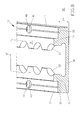
- the Fig. 1 to 4 show a securing rail 10 according to the invention in a first embodiment.
- the safety rail 10 has on its longitudinal sides 14 each have a solid area 15.
- holes 20 are introduced through which fastening means 40 are feasible to secure the safety rail 10 on a surface 42.
- These holes 20 are formed here as lowered holes 21.
- countersunk screws can be added as fastening means 40, as in Fig. 4 shown.
- the bottom 16 of the securing rail 10 is thin-walled. This saves 10 compared to conventional security rails of material.
- the material is not necessary in the inventive safety rails 10, since the attachment is not made by fastening means 40 which are guided through the bottom 16, but by fastening means 40 which are guided through the solid areas 15.
- the inserted into the lowered holes 21 fasteners 40 in the form of countersunk screws are not on the top 11 of the safety rail 10 out, but are introduced with their head 41 in the lowered hole 21 and thus aligned with the top 11 of the safety rail 10, as in particular Fig. 4 evident.
- the surface 42 is shown here only indicated.
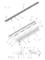
- FIG. 5 to 8 Another advantageous embodiment of the invention show the Fig. 5 to 8 , Here, the solid area 15 of the securing rail 10 is formed with a reduced height 22. As a result, additional material for the safety rail 10 is saved. Again, the bottom 16 of the safety rail 10 is again thin-walled. Due to the additional material savings, the cost of the safety rail 10 can be further reduced.
- the screws, which are used as fasteners 40 in Fig. 8 serve to secure the securing rail 10 to the indicated area 42, are simple cylinder head bolts. Although the heads 41 of the fastening means 40 protrude from the surface of the solid area 15, they do not protrude from the upper side 11 of the securing rail 10, since the solid areas 15 have the reduced height 22 already mentioned.
- the cheapest embodiment shown here of the safety rail 10 according to the invention is in the Fig. 9 to 12 shown.
- the safety rail 10 is formed as a parallel profile pair 30.
- the solid areas 15 of the securing rail 10 are also formed again with reduced height 22 and the holes 20 designed as simple through holes.
- a bottom 16 is not provided in this safety rail 10.
- An additional very significant saving results from the fact that machining of the individual profiles of the profile pair 30 is not done by a machining.
- a machining, for example for the production of the recesses 12 or lowered holes 21, can be omitted here.
- the single profile of the profile pair 30 is produced by extrusion, wherein the holes 20 and the regions of the recesses 12 can be produced by stamping.
- Both individual profiles of the profile pair 30 are identical to each other and are arranged only rotated by 180 °.
- the recesses 12 are then formed between the individual profiles of the profile pair 30.
- a fastener 40 here again simple cylinder head bolts can be used, as already described in the second embodiment.
Landscapes
- Engineering & Computer Science (AREA)
- Transportation (AREA)
- Mechanical Engineering (AREA)
- Body Structure For Vehicles (AREA)
- Vehicle Interior And Exterior Ornaments, Soundproofing, And Insulation (AREA)
- Connection Of Plates (AREA)
Applications Claiming Priority (1)
| Application Number | Priority Date | Filing Date | Title |
|---|---|---|---|
| DE102014105440.7A DE102014105440A1 (de) | 2014-04-16 | 2014-04-16 | Sicherungsschiene zum Einbau in Fahrzeuge |
Publications (3)
| Publication Number | Publication Date |
|---|---|
| EP2933140A2 true EP2933140A2 (fr) | 2015-10-21 |
| EP2933140A3 EP2933140A3 (fr) | 2016-02-17 |
| EP2933140B1 EP2933140B1 (fr) | 2018-12-19 |
Family
ID=52823505
Family Applications (1)
| Application Number | Title | Priority Date | Filing Date |
|---|---|---|---|
| EP15162697.5A Not-in-force EP2933140B1 (fr) | 2014-04-16 | 2015-04-08 | Rails de sécurité à installer dans des véhicules |
Country Status (2)
| Country | Link |
|---|---|
| EP (1) | EP2933140B1 (fr) |
| DE (1) | DE102014105440A1 (fr) |
Cited By (2)
| Publication number | Priority date | Publication date | Assignee | Title |
|---|---|---|---|---|
| US20240090694A1 (en) * | 2022-09-19 | 2024-03-21 | James W. Thum | Modular Mantel Hook Apparatus |
| US12496956B2 (en) | 2021-10-22 | 2025-12-16 | Adrian Steel Company | Selective retention system |
Family Cites Families (7)
| Publication number | Priority date | Publication date | Assignee | Title |
|---|---|---|---|---|
| DE6941229U (de) * | 1969-10-22 | 1970-02-12 | Sehlbach Herbert Schmalweberei | Einhaengebeschlag fuer ladungssicherungsgurte. |
| DK0588761T3 (da) * | 1992-09-17 | 1996-04-09 | Alusuisse Lonza Services Ag | Indretning til sikring af lastgods |
| DE9307052U1 (de) * | 1993-05-10 | 1993-10-21 | Schmitz, Peter, 48341 Altenberge | Wandplatte für Fahrzeugaufbauten |
| DE4341230C2 (de) * | 1993-12-03 | 2001-07-19 | Elze Waggonbau Gmbh & Co Kg | Großcontainer |
| DE102005061493B4 (de) * | 2005-12-22 | 2010-09-09 | Kipp Gmbh & Co. Kg Cargo & Safety Systems | Gepäckhalteeinrichtung |
| DE102006025118B4 (de) * | 2006-05-30 | 2009-12-03 | Ackermann Fahrzeugbau Gmbh | Fahrzeug |
| DE102009018487B4 (de) * | 2008-05-02 | 2020-06-18 | Goodrich Corp. | Verfahren und Vorrichtung zum Sichern von Frachtgut in einem Flugzeug |
-
2014
- 2014-04-16 DE DE102014105440.7A patent/DE102014105440A1/de not_active Withdrawn
-
2015
- 2015-04-08 EP EP15162697.5A patent/EP2933140B1/fr not_active Not-in-force
Non-Patent Citations (1)
| Title |
|---|
| None |
Cited By (3)
| Publication number | Priority date | Publication date | Assignee | Title |
|---|---|---|---|---|
| US12496956B2 (en) | 2021-10-22 | 2025-12-16 | Adrian Steel Company | Selective retention system |
| US20240090694A1 (en) * | 2022-09-19 | 2024-03-21 | James W. Thum | Modular Mantel Hook Apparatus |
| US12193586B2 (en) * | 2022-09-19 | 2025-01-14 | James W. Thum | Modular mantel hook apparatus |
Also Published As
| Publication number | Publication date |
|---|---|
| EP2933140B1 (fr) | 2018-12-19 |
| EP2933140A3 (fr) | 2016-02-17 |
| DE102014105440A1 (de) | 2015-10-22 |
Similar Documents
| Publication | Publication Date | Title |
|---|---|---|
| EP1721786B1 (fr) | Système de pare-chocs | |
| DE102006043763B4 (de) | Auswechselbares Verschleißpolster, sowie Gleiskette | |
| DE212015000088U1 (de) | Mutter zum Befestigen eines Objekts an einer Baustruktur | |
| EP3649353A1 (fr) | Système de fixation | |
| EP0688962A1 (fr) | Connexion d'angle | |
| EP3224426A1 (fr) | Moyen d'assemblage verrouillable | |
| DE2819972A1 (de) | Aufnahmetasche fuer ein befestigungselement in einem gegenstand aus thermoplastischem werkstoff | |
| EP2933140B1 (fr) | Rails de sécurité à installer dans des véhicules | |
| DE102016004587A1 (de) | Profilsystem zur Bildung eines Untertragrahmens für die Aufnahme von Bodendielen und Profilschiene | |
| EP1601835B1 (fr) | Coeur de croisement de rails a gorge | |
| DE202020000004U1 (de) | Befestigungsvorrichtung für eine Dachlast | |
| DE102020111132A1 (de) | Profilstrebe, insbesondere für ein Kraftfahrzeug | |
| EP3227495B1 (fr) | Joint de chaussee avec elements a peigne | |
| EP3395611A1 (fr) | Rail d'arrimage, espace de chargement, véhicule | |
| DE602006001035T2 (de) | Befestigungssystem für Profile | |
| EP2933141B1 (fr) | Rails de sécurité à installer dans des véhicules | |
| EP4385884A1 (fr) | Système de rails de siège pour cabine de véhicule de transport | |
| DE202016104146U1 (de) | Nischenpoller | |
| BE1022940B1 (de) | Arretierbares Verbindungsmittel | |
| DE102013114443A1 (de) | Bodenprofil zur Befestigung von Fahrzeugeinrichtungen in Fahrzeugen | |
| DE102016000910A1 (de) | Nutzfahrzeugaufbau | |
| EP2910420A2 (fr) | Rails d'ancrage pour la fixation de marchandises | |
| DE202013003846U1 (de) | Befestigungsvorrichtung | |
| DE202020003458U1 (de) | Zusatzvorrichtung für eine Dachlastbefestigung | |
| DE102010015574A1 (de) | Trennwandsystem |
Legal Events
| Date | Code | Title | Description |
|---|---|---|---|
| PUAI | Public reference made under article 153(3) epc to a published international application that has entered the european phase |
Free format text: ORIGINAL CODE: 0009012 |
|
| AK | Designated contracting states |
Kind code of ref document: A2 Designated state(s): AL AT BE BG CH CY CZ DE DK EE ES FI FR GB GR HR HU IE IS IT LI LT LU LV MC MK MT NL NO PL PT RO RS SE SI SK SM TR |
|
| AX | Request for extension of the european patent |
Extension state: BA ME |
|
| PUAL | Search report despatched |
Free format text: ORIGINAL CODE: 0009013 |
|
| AK | Designated contracting states |
Kind code of ref document: A3 Designated state(s): AL AT BE BG CH CY CZ DE DK EE ES FI FR GB GR HR HU IE IS IT LI LT LU LV MC MK MT NL NO PL PT RO RS SE SI SK SM TR |
|
| AX | Request for extension of the european patent |
Extension state: BA ME |
|
| RIC1 | Information provided on ipc code assigned before grant |
Ipc: B60P 7/08 20060101AFI20160114BHEP |
|
| 17P | Request for examination filed |
Effective date: 20160426 |
|
| RBV | Designated contracting states (corrected) |
Designated state(s): AL AT BE BG CH CY CZ DE DK EE ES FI FR GB GR HR HU IE IS IT LI LT LU LV MC MK MT NL NO PL PT RO RS SE SI SK SM TR |
|
| GRAP | Despatch of communication of intention to grant a patent |
Free format text: ORIGINAL CODE: EPIDOSNIGR1 |
|
| STAA | Information on the status of an ep patent application or granted ep patent |
Free format text: STATUS: GRANT OF PATENT IS INTENDED |
|
| INTG | Intention to grant announced |
Effective date: 20180906 |
|
| GRAS | Grant fee paid |
Free format text: ORIGINAL CODE: EPIDOSNIGR3 |
|
| GRAA | (expected) grant |
Free format text: ORIGINAL CODE: 0009210 |
|
| STAA | Information on the status of an ep patent application or granted ep patent |
Free format text: STATUS: THE PATENT HAS BEEN GRANTED |
|
| AK | Designated contracting states |
Kind code of ref document: B1 Designated state(s): AL AT BE BG CH CY CZ DE DK EE ES FI FR GB GR HR HU IE IS IT LI LT LU LV MC MK MT NL NO PL PT RO RS SE SI SK SM TR |
|
| REG | Reference to a national code |
Ref country code: GB Ref legal event code: FG4D Free format text: NOT ENGLISH |
|
| REG | Reference to a national code |
Ref country code: CH Ref legal event code: EP |
|
| REG | Reference to a national code |
Ref country code: IE Ref legal event code: FG4D Free format text: LANGUAGE OF EP DOCUMENT: GERMAN |
|
| REG | Reference to a national code |
Ref country code: DE Ref legal event code: R096 Ref document number: 502015007293 Country of ref document: DE |
|
| REG | Reference to a national code |
Ref country code: AT Ref legal event code: REF Ref document number: 1078315 Country of ref document: AT Kind code of ref document: T Effective date: 20190115 |
|
| REG | Reference to a national code |
Ref country code: NL Ref legal event code: MP Effective date: 20181219 |
|
| PG25 | Lapsed in a contracting state [announced via postgrant information from national office to epo] |
Ref country code: HR Free format text: LAPSE BECAUSE OF FAILURE TO SUBMIT A TRANSLATION OF THE DESCRIPTION OR TO PAY THE FEE WITHIN THE PRESCRIBED TIME-LIMIT Effective date: 20181219 Ref country code: LT Free format text: LAPSE BECAUSE OF FAILURE TO SUBMIT A TRANSLATION OF THE DESCRIPTION OR TO PAY THE FEE WITHIN THE PRESCRIBED TIME-LIMIT Effective date: 20181219 Ref country code: BG Free format text: LAPSE BECAUSE OF FAILURE TO SUBMIT A TRANSLATION OF THE DESCRIPTION OR TO PAY THE FEE WITHIN THE PRESCRIBED TIME-LIMIT Effective date: 20190319 Ref country code: FI Free format text: LAPSE BECAUSE OF FAILURE TO SUBMIT A TRANSLATION OF THE DESCRIPTION OR TO PAY THE FEE WITHIN THE PRESCRIBED TIME-LIMIT Effective date: 20181219 Ref country code: LV Free format text: LAPSE BECAUSE OF FAILURE TO SUBMIT A TRANSLATION OF THE DESCRIPTION OR TO PAY THE FEE WITHIN THE PRESCRIBED TIME-LIMIT Effective date: 20181219 Ref country code: NO Free format text: LAPSE BECAUSE OF FAILURE TO SUBMIT A TRANSLATION OF THE DESCRIPTION OR TO PAY THE FEE WITHIN THE PRESCRIBED TIME-LIMIT Effective date: 20190319 |
|
| REG | Reference to a national code |
Ref country code: LT Ref legal event code: MG4D |
|
| PG25 | Lapsed in a contracting state [announced via postgrant information from national office to epo] |
Ref country code: GR Free format text: LAPSE BECAUSE OF FAILURE TO SUBMIT A TRANSLATION OF THE DESCRIPTION OR TO PAY THE FEE WITHIN THE PRESCRIBED TIME-LIMIT Effective date: 20190320 Ref country code: RS Free format text: LAPSE BECAUSE OF FAILURE TO SUBMIT A TRANSLATION OF THE DESCRIPTION OR TO PAY THE FEE WITHIN THE PRESCRIBED TIME-LIMIT Effective date: 20181219 Ref country code: SE Free format text: LAPSE BECAUSE OF FAILURE TO SUBMIT A TRANSLATION OF THE DESCRIPTION OR TO PAY THE FEE WITHIN THE PRESCRIBED TIME-LIMIT Effective date: 20181219 Ref country code: AL Free format text: LAPSE BECAUSE OF FAILURE TO SUBMIT A TRANSLATION OF THE DESCRIPTION OR TO PAY THE FEE WITHIN THE PRESCRIBED TIME-LIMIT Effective date: 20181219 |
|
| PG25 | Lapsed in a contracting state [announced via postgrant information from national office to epo] |
Ref country code: NL Free format text: LAPSE BECAUSE OF FAILURE TO SUBMIT A TRANSLATION OF THE DESCRIPTION OR TO PAY THE FEE WITHIN THE PRESCRIBED TIME-LIMIT Effective date: 20181219 |
|
| PG25 | Lapsed in a contracting state [announced via postgrant information from national office to epo] |
Ref country code: PL Free format text: LAPSE BECAUSE OF FAILURE TO SUBMIT A TRANSLATION OF THE DESCRIPTION OR TO PAY THE FEE WITHIN THE PRESCRIBED TIME-LIMIT Effective date: 20181219 Ref country code: ES Free format text: LAPSE BECAUSE OF FAILURE TO SUBMIT A TRANSLATION OF THE DESCRIPTION OR TO PAY THE FEE WITHIN THE PRESCRIBED TIME-LIMIT Effective date: 20181219 Ref country code: PT Free format text: LAPSE BECAUSE OF FAILURE TO SUBMIT A TRANSLATION OF THE DESCRIPTION OR TO PAY THE FEE WITHIN THE PRESCRIBED TIME-LIMIT Effective date: 20190419 Ref country code: CZ Free format text: LAPSE BECAUSE OF FAILURE TO SUBMIT A TRANSLATION OF THE DESCRIPTION OR TO PAY THE FEE WITHIN THE PRESCRIBED TIME-LIMIT Effective date: 20181219 Ref country code: IT Free format text: LAPSE BECAUSE OF FAILURE TO SUBMIT A TRANSLATION OF THE DESCRIPTION OR TO PAY THE FEE WITHIN THE PRESCRIBED TIME-LIMIT Effective date: 20181219 |
|
| PG25 | Lapsed in a contracting state [announced via postgrant information from national office to epo] |
Ref country code: SK Free format text: LAPSE BECAUSE OF FAILURE TO SUBMIT A TRANSLATION OF THE DESCRIPTION OR TO PAY THE FEE WITHIN THE PRESCRIBED TIME-LIMIT Effective date: 20181219 Ref country code: SM Free format text: LAPSE BECAUSE OF FAILURE TO SUBMIT A TRANSLATION OF THE DESCRIPTION OR TO PAY THE FEE WITHIN THE PRESCRIBED TIME-LIMIT Effective date: 20181219 Ref country code: EE Free format text: LAPSE BECAUSE OF FAILURE TO SUBMIT A TRANSLATION OF THE DESCRIPTION OR TO PAY THE FEE WITHIN THE PRESCRIBED TIME-LIMIT Effective date: 20181219 Ref country code: RO Free format text: LAPSE BECAUSE OF FAILURE TO SUBMIT A TRANSLATION OF THE DESCRIPTION OR TO PAY THE FEE WITHIN THE PRESCRIBED TIME-LIMIT Effective date: 20181219 Ref country code: IS Free format text: LAPSE BECAUSE OF FAILURE TO SUBMIT A TRANSLATION OF THE DESCRIPTION OR TO PAY THE FEE WITHIN THE PRESCRIBED TIME-LIMIT Effective date: 20190419 |
|
| REG | Reference to a national code |
Ref country code: DE Ref legal event code: R097 Ref document number: 502015007293 Country of ref document: DE |
|
| PLBE | No opposition filed within time limit |
Free format text: ORIGINAL CODE: 0009261 |
|
| STAA | Information on the status of an ep patent application or granted ep patent |
Free format text: STATUS: NO OPPOSITION FILED WITHIN TIME LIMIT |
|
| PG25 | Lapsed in a contracting state [announced via postgrant information from national office to epo] |
Ref country code: DK Free format text: LAPSE BECAUSE OF FAILURE TO SUBMIT A TRANSLATION OF THE DESCRIPTION OR TO PAY THE FEE WITHIN THE PRESCRIBED TIME-LIMIT Effective date: 20181219 |
|
| 26N | No opposition filed |
Effective date: 20190920 |
|
| REG | Reference to a national code |
Ref country code: CH Ref legal event code: PL |
|
| REG | Reference to a national code |
Ref country code: BE Ref legal event code: MM Effective date: 20190430 |
|
| GBPC | Gb: european patent ceased through non-payment of renewal fee |
Effective date: 20190408 |
|
| PG25 | Lapsed in a contracting state [announced via postgrant information from national office to epo] |
Ref country code: MC Free format text: LAPSE BECAUSE OF FAILURE TO SUBMIT A TRANSLATION OF THE DESCRIPTION OR TO PAY THE FEE WITHIN THE PRESCRIBED TIME-LIMIT Effective date: 20181219 Ref country code: LU Free format text: LAPSE BECAUSE OF NON-PAYMENT OF DUE FEES Effective date: 20190408 |
|
| PG25 | Lapsed in a contracting state [announced via postgrant information from national office to epo] |
Ref country code: CH Free format text: LAPSE BECAUSE OF NON-PAYMENT OF DUE FEES Effective date: 20190430 Ref country code: LI Free format text: LAPSE BECAUSE OF NON-PAYMENT OF DUE FEES Effective date: 20190430 Ref country code: GB Free format text: LAPSE BECAUSE OF NON-PAYMENT OF DUE FEES Effective date: 20190408 |
|
| PG25 | Lapsed in a contracting state [announced via postgrant information from national office to epo] |
Ref country code: SI Free format text: LAPSE BECAUSE OF FAILURE TO SUBMIT A TRANSLATION OF THE DESCRIPTION OR TO PAY THE FEE WITHIN THE PRESCRIBED TIME-LIMIT Effective date: 20181219 Ref country code: BE Free format text: LAPSE BECAUSE OF NON-PAYMENT OF DUE FEES Effective date: 20190430 Ref country code: FR Free format text: LAPSE BECAUSE OF NON-PAYMENT OF DUE FEES Effective date: 20190430 |
|
| PG25 | Lapsed in a contracting state [announced via postgrant information from national office to epo] |
Ref country code: TR Free format text: LAPSE BECAUSE OF FAILURE TO SUBMIT A TRANSLATION OF THE DESCRIPTION OR TO PAY THE FEE WITHIN THE PRESCRIBED TIME-LIMIT Effective date: 20181219 |
|
| PG25 | Lapsed in a contracting state [announced via postgrant information from national office to epo] |
Ref country code: IE Free format text: LAPSE BECAUSE OF NON-PAYMENT OF DUE FEES Effective date: 20190408 |
|
| PGFP | Annual fee paid to national office [announced via postgrant information from national office to epo] |
Ref country code: DE Payment date: 20200327 Year of fee payment: 6 |
|
| PG25 | Lapsed in a contracting state [announced via postgrant information from national office to epo] |
Ref country code: CY Free format text: LAPSE BECAUSE OF FAILURE TO SUBMIT A TRANSLATION OF THE DESCRIPTION OR TO PAY THE FEE WITHIN THE PRESCRIBED TIME-LIMIT Effective date: 20181219 |
|
| REG | Reference to a national code |
Ref country code: AT Ref legal event code: MM01 Ref document number: 1078315 Country of ref document: AT Kind code of ref document: T Effective date: 20200408 |
|
| PG25 | Lapsed in a contracting state [announced via postgrant information from national office to epo] |
Ref country code: MT Free format text: LAPSE BECAUSE OF FAILURE TO SUBMIT A TRANSLATION OF THE DESCRIPTION OR TO PAY THE FEE WITHIN THE PRESCRIBED TIME-LIMIT Effective date: 20181219 Ref country code: HU Free format text: LAPSE BECAUSE OF FAILURE TO SUBMIT A TRANSLATION OF THE DESCRIPTION OR TO PAY THE FEE WITHIN THE PRESCRIBED TIME-LIMIT; INVALID AB INITIO Effective date: 20150408 |
|
| PG25 | Lapsed in a contracting state [announced via postgrant information from national office to epo] |
Ref country code: AT Free format text: LAPSE BECAUSE OF NON-PAYMENT OF DUE FEES Effective date: 20200408 |
|
| REG | Reference to a national code |
Ref country code: DE Ref legal event code: R119 Ref document number: 502015007293 Country of ref document: DE |
|
| PG25 | Lapsed in a contracting state [announced via postgrant information from national office to epo] |
Ref country code: DE Free format text: LAPSE BECAUSE OF NON-PAYMENT OF DUE FEES Effective date: 20211103 |
|
| PG25 | Lapsed in a contracting state [announced via postgrant information from national office to epo] |
Ref country code: MK Free format text: LAPSE BECAUSE OF FAILURE TO SUBMIT A TRANSLATION OF THE DESCRIPTION OR TO PAY THE FEE WITHIN THE PRESCRIBED TIME-LIMIT Effective date: 20181219 |