EP2933193B1 - Protection pour un dispositif de contrôle de température ainsi que procédé de fabrication et utilisation d'une telle protection - Google Patents
Protection pour un dispositif de contrôle de température ainsi que procédé de fabrication et utilisation d'une telle protection Download PDFInfo
- Publication number
- EP2933193B1 EP2933193B1 EP14001405.1A EP14001405A EP2933193B1 EP 2933193 B1 EP2933193 B1 EP 2933193B1 EP 14001405 A EP14001405 A EP 14001405A EP 2933193 B1 EP2933193 B1 EP 2933193B1
- Authority
- EP
- European Patent Office
- Prior art keywords
- shroud
- duct
- cooling
- heat exchanger
- exchanger body
- Prior art date
- Legal status (The legal status is an assumption and is not a legal conclusion. Google has not performed a legal analysis and makes no representation as to the accuracy of the status listed.)
- Active
Links
Images



Classifications
-
- F—MECHANICAL ENGINEERING; LIGHTING; HEATING; WEAPONS; BLASTING
- F25—REFRIGERATION OR COOLING; COMBINED HEATING AND REFRIGERATION SYSTEMS; HEAT PUMP SYSTEMS; MANUFACTURE OR STORAGE OF ICE; LIQUEFACTION SOLIDIFICATION OF GASES
- F25D—REFRIGERATORS; COLD ROOMS; ICE-BOXES; COOLING OR FREEZING APPARATUS NOT OTHERWISE PROVIDED FOR
- F25D3/00—Devices using other cold materials; Devices using cold-storage bodies
- F25D3/10—Devices using other cold materials; Devices using cold-storage bodies using liquefied gases, e.g. liquid air
- F25D3/102—Stationary cabinets
-
- B—PERFORMING OPERATIONS; TRANSPORTING
- B64—AIRCRAFT; AVIATION; COSMONAUTICS
- B64G—COSMONAUTICS; VEHICLES OR EQUIPMENT THEREFOR
- B64G7/00—Simulating cosmonautic conditions, e.g. for conditioning crews
-
- F—MECHANICAL ENGINEERING; LIGHTING; HEATING; WEAPONS; BLASTING
- F28—HEAT EXCHANGE IN GENERAL
- F28D—HEAT-EXCHANGE APPARATUS, NOT PROVIDED FOR IN ANOTHER SUBCLASS, IN WHICH THE HEAT-EXCHANGE MEDIA DO NOT COME INTO DIRECT CONTACT
- F28D1/00—Heat-exchange apparatus having stationary conduit assemblies for one heat-exchange medium only, the media being in contact with different sides of the conduit wall, in which the other heat-exchange medium is a large body of fluid, e.g. domestic or motor car radiators
- F28D1/02—Heat-exchange apparatus having stationary conduit assemblies for one heat-exchange medium only, the media being in contact with different sides of the conduit wall, in which the other heat-exchange medium is a large body of fluid, e.g. domestic or motor car radiators with heat-exchange conduits immersed in the body of fluid
- F28D1/04—Heat-exchange apparatus having stationary conduit assemblies for one heat-exchange medium only, the media being in contact with different sides of the conduit wall, in which the other heat-exchange medium is a large body of fluid, e.g. domestic or motor car radiators with heat-exchange conduits immersed in the body of fluid with tubular conduits
- F28D1/047—Heat-exchange apparatus having stationary conduit assemblies for one heat-exchange medium only, the media being in contact with different sides of the conduit wall, in which the other heat-exchange medium is a large body of fluid, e.g. domestic or motor car radiators with heat-exchange conduits immersed in the body of fluid with tubular conduits the conduits being bent, e.g. in a serpentine or zig-zag
- F28D1/0475—Heat-exchange apparatus having stationary conduit assemblies for one heat-exchange medium only, the media being in contact with different sides of the conduit wall, in which the other heat-exchange medium is a large body of fluid, e.g. domestic or motor car radiators with heat-exchange conduits immersed in the body of fluid with tubular conduits the conduits being bent, e.g. in a serpentine or zig-zag the conduits having a single U-bend
-
- F—MECHANICAL ENGINEERING; LIGHTING; HEATING; WEAPONS; BLASTING
- F28—HEAT EXCHANGE IN GENERAL
- F28D—HEAT-EXCHANGE APPARATUS, NOT PROVIDED FOR IN ANOTHER SUBCLASS, IN WHICH THE HEAT-EXCHANGE MEDIA DO NOT COME INTO DIRECT CONTACT
- F28D1/00—Heat-exchange apparatus having stationary conduit assemblies for one heat-exchange medium only, the media being in contact with different sides of the conduit wall, in which the other heat-exchange medium is a large body of fluid, e.g. domestic or motor car radiators
- F28D1/02—Heat-exchange apparatus having stationary conduit assemblies for one heat-exchange medium only, the media being in contact with different sides of the conduit wall, in which the other heat-exchange medium is a large body of fluid, e.g. domestic or motor car radiators with heat-exchange conduits immersed in the body of fluid
- F28D1/04—Heat-exchange apparatus having stationary conduit assemblies for one heat-exchange medium only, the media being in contact with different sides of the conduit wall, in which the other heat-exchange medium is a large body of fluid, e.g. domestic or motor car radiators with heat-exchange conduits immersed in the body of fluid with tubular conduits
- F28D1/047—Heat-exchange apparatus having stationary conduit assemblies for one heat-exchange medium only, the media being in contact with different sides of the conduit wall, in which the other heat-exchange medium is a large body of fluid, e.g. domestic or motor car radiators with heat-exchange conduits immersed in the body of fluid with tubular conduits the conduits being bent, e.g. in a serpentine or zig-zag
- F28D1/0477—Heat-exchange apparatus having stationary conduit assemblies for one heat-exchange medium only, the media being in contact with different sides of the conduit wall, in which the other heat-exchange medium is a large body of fluid, e.g. domestic or motor car radiators with heat-exchange conduits immersed in the body of fluid with tubular conduits the conduits being bent, e.g. in a serpentine or zig-zag the conduits being bent in a serpentine or zig-zag
-
- F—MECHANICAL ENGINEERING; LIGHTING; HEATING; WEAPONS; BLASTING
- F28—HEAT EXCHANGE IN GENERAL
- F28F—DETAILS OF HEAT-EXCHANGE AND HEAT-TRANSFER APPARATUS, OF GENERAL APPLICATION
- F28F21/00—Constructions of heat-exchange apparatus characterised by the selection of particular materials
- F28F21/08—Constructions of heat-exchange apparatus characterised by the selection of particular materials of metal
- F28F21/081—Heat exchange elements made from metals or metal alloys
- F28F21/084—Heat exchange elements made from metals or metal alloys from aluminium or aluminium alloys
-
- F—MECHANICAL ENGINEERING; LIGHTING; HEATING; WEAPONS; BLASTING
- F28—HEAT EXCHANGE IN GENERAL
- F28F—DETAILS OF HEAT-EXCHANGE AND HEAT-TRANSFER APPARATUS, OF GENERAL APPLICATION
- F28F3/00—Plate-like or laminated elements; Assemblies of plate-like or laminated elements
- F28F3/12—Elements constructed in the shape of a hollow panel, e.g. with channels
-
- B—PERFORMING OPERATIONS; TRANSPORTING
- B64—AIRCRAFT; AVIATION; COSMONAUTICS
- B64G—COSMONAUTICS; VEHICLES OR EQUIPMENT THEREFOR
- B64G7/00—Simulating cosmonautic conditions, e.g. for conditioning crews
- B64G2007/005—Space simulation vacuum chambers
-
- F—MECHANICAL ENGINEERING; LIGHTING; HEATING; WEAPONS; BLASTING
- F28—HEAT EXCHANGE IN GENERAL
- F28D—HEAT-EXCHANGE APPARATUS, NOT PROVIDED FOR IN ANOTHER SUBCLASS, IN WHICH THE HEAT-EXCHANGE MEDIA DO NOT COME INTO DIRECT CONTACT
- F28D1/00—Heat-exchange apparatus having stationary conduit assemblies for one heat-exchange medium only, the media being in contact with different sides of the conduit wall, in which the other heat-exchange medium is a large body of fluid, e.g. domestic or motor car radiators
- F28D1/02—Heat-exchange apparatus having stationary conduit assemblies for one heat-exchange medium only, the media being in contact with different sides of the conduit wall, in which the other heat-exchange medium is a large body of fluid, e.g. domestic or motor car radiators with heat-exchange conduits immersed in the body of fluid
- F28D1/04—Heat-exchange apparatus having stationary conduit assemblies for one heat-exchange medium only, the media being in contact with different sides of the conduit wall, in which the other heat-exchange medium is a large body of fluid, e.g. domestic or motor car radiators with heat-exchange conduits immersed in the body of fluid with tubular conduits
- F28D1/053—Heat-exchange apparatus having stationary conduit assemblies for one heat-exchange medium only, the media being in contact with different sides of the conduit wall, in which the other heat-exchange medium is a large body of fluid, e.g. domestic or motor car radiators with heat-exchange conduits immersed in the body of fluid with tubular conduits the conduits being straight
- F28D1/05316—Assemblies of conduits connected to common headers, e.g. core type radiators
-
- F—MECHANICAL ENGINEERING; LIGHTING; HEATING; WEAPONS; BLASTING
- F28—HEAT EXCHANGE IN GENERAL
- F28D—HEAT-EXCHANGE APPARATUS, NOT PROVIDED FOR IN ANOTHER SUBCLASS, IN WHICH THE HEAT-EXCHANGE MEDIA DO NOT COME INTO DIRECT CONTACT
- F28D21/00—Heat-exchange apparatus not covered by any of the groups F28D1/00 - F28D20/00
- F28D2021/0019—Other heat exchangers for particular applications; Heat exchange systems not otherwise provided for
- F28D2021/0021—Other heat exchangers for particular applications; Heat exchange systems not otherwise provided for for aircrafts or cosmonautics
-
- F—MECHANICAL ENGINEERING; LIGHTING; HEATING; WEAPONS; BLASTING
- F28—HEAT EXCHANGE IN GENERAL
- F28F—DETAILS OF HEAT-EXCHANGE AND HEAT-TRANSFER APPARATUS, OF GENERAL APPLICATION
- F28F1/00—Tubular elements; Assemblies of tubular elements
- F28F1/10—Tubular elements and assemblies thereof with means for increasing heat-transfer area, e.g. with fins, with projections, with recesses
- F28F1/12—Tubular elements and assemblies thereof with means for increasing heat-transfer area, e.g. with fins, with projections, with recesses the means being only outside the tubular element
- F28F1/24—Tubular elements and assemblies thereof with means for increasing heat-transfer area, e.g. with fins, with projections, with recesses the means being only outside the tubular element and extending transversely
- F28F1/32—Tubular elements and assemblies thereof with means for increasing heat-transfer area, e.g. with fins, with projections, with recesses the means being only outside the tubular element and extending transversely the means having portions engaging further tubular elements
-
- F—MECHANICAL ENGINEERING; LIGHTING; HEATING; WEAPONS; BLASTING
- F28—HEAT EXCHANGE IN GENERAL
- F28F—DETAILS OF HEAT-EXCHANGE AND HEAT-TRANSFER APPARATUS, OF GENERAL APPLICATION
- F28F2255/00—Heat exchanger elements made of materials having special features or resulting from particular manufacturing processes
- F28F2255/14—Heat exchanger elements made of materials having special features or resulting from particular manufacturing processes molded
- F28F2255/146—Heat exchanger elements made of materials having special features or resulting from particular manufacturing processes molded overmolded
Definitions
- the invention relates to a shroud for a temperature control device and to a method for producing a shroud, the shroud being arrangeable in a temperature chamber, the shroud having a feeding duct, a discharge duct and at least one cooling duct for a gaseous and/or liquid cooling medium, the cooling duct serving to cool the temperature chamber and being connected to the feeding duct and to the discharge duct, the shroud having at least one electric heating element, which serves to heat the temperature chamber, the shroud has at least one heat exchanger body for cooling and heating the temperature chamber.
- the invention further relates to a use of such a shroud.
- Temperature chambers are regularly used for various purposes, such as for treating, measuring or testing products. Temperature chambers regularly comprise a closable temperature room, in which the product(s) can be arranged. Depending on the type of product, the temperature room can have a correspondingly adapted size and shape and provide a temperature in a range of -196° C to +200° C.
- a field of application for temperature chambers of this kind is a testing of products for aerospace, for example, because extremely large temperature differences within short time can occur naturally in said field.
- known temperature chambers are regularly provided with a temperature control device including shrouds and lining elements respectively in the area of a temperature room of the temperature chamber.
- the temperature room can be surrounded by a plurality of shrouds, by means of which high and low temperatures can be generated in the temperature chamber and in a specimen respectively by conduction and/or radiation in a comparatively quick manner.
- the shrouds can be regulated independently so as a specimen ca be cooled on one side and heated on another side.
- the shrouds can simulate a rotation of a temperature which represents a rotation of a satellite on an orbital trajectory.
- a temperature chamber whose temperature room is surrounded by shrouds on all sides.
- the shrouds can be cooled and brought to a very low temperature by means of liquid nitrogen via a feeding duct, the nitrogen being discharged via a discharge duct.
- the liquid nitrogen is led through a cooling duct of the shroud in the area of the temperature room.
- an electric heating element with a reflector is arranged on a rearward side of the cooling duct, which is facing away from the temperature room. If the temperature room is to be heated to a higher temperature after it has been cooled, the electric heating element or the electric heating elements of the shrouds are turned on, heat radiation of the electric heating elements being reflected by the reflectors in the direction of the temperature room.
- gaseous or liquid cooling medium can be fed to the cooling duct via the feeding duct.
- a blower can be arranged in the feeding duct, by which a sufficiently large volume flow or media pressure can be generated in the feeding duct.
- the blower ensures the mass flow of cooling medium required for generating a temperature of -196° C, for example. It is disadvantageous, however, that at such low temperatures leaks can easily occur in the area of the blower and the blower may fail. It is further disadvantageous in the known temperature control devices that they require large amounts of the cooling medium in order to be able to reach lowest temperatures at all. Also, a temperature change from very high to very low temperatures and vice versa happens only slowly.
- FR 1 573 389 A discloses a shroud for a temperature control device of a temperature chamber, the shroud is arranged in a temperature chamber and has a feeding duct, a discharge duct and at least one cooling duct for a gaseous and/or liquid cooling medium.
- the cooling duct serves to cool the temperature chamber and is connected to the feeding duct and to the discharge duct.
- the shroud has at least one electric heating element, which serves to heat the temperature chamber, and at least one heat exchanger body for cooling and heating the temperature chamber.
- the cooling duct and the electric heating element are arranged on the heat exchanger body.
- the shroud according to the invention for a temperature control device can be arranged in a temperature chamber, the shroud having a feeding duct, a discharge duct and at least one cooling duct for a gaseous and/or liquid cooling medium, the cooling duct serving to cool the temperature chamber and being connected to the feeding duct and to the discharge duct, the shroud having at least one electric heating element, which serves to heat the temperature chamber, the shroud having at least one heat exchanger body for cooling and heating the temperature chamber, the cooling duct and the electric heating element being arranged in the heat exchanger body, said heat exchanger body being formed of cast metal in which the cooling duct and the electric heating element are at least partially arranged.
- a selective cooling and heating of the temperature chamber and a change between high and low temperatures and vice versa can take place comparatively quickly in particular due to the fact that the shroud comprises the heat exchanger body with the cooling duct and the electric heating element being arranged in the heat exchanger. This is made possible in particular by the fact that a heat exchanger surface between the cooling duct and the electric heating element is substantially enlarged because the cooling duct and the electric heating element are arranged or positioned together within the heat exchanger body. Also, a direct cooling or heating of the heat exchanger body becomes possible in this way, wherein the heating element can be cooled and the cooling duct can be heated.
- a quick temperature change of the heat exchanger body in this case results in particular from the fact that a large temperature difference can be produced between the cooling duct and the heating element, which can directly affect a temperature of the cooling duct or of the heating element when they are heated and cooled, respectively.
- a required mass flow of the cooling medium or a consumption of electrical energy can also be reduced, the temperature control device thus being operable in a more cost-effective manner.
- the cooling duct and the electric heating element can be arranged in a common plane in the heat exchanger body.
- the arrangement of the electric heating element and of the cooling duct in a common plane simplifies production of the heat exchanger body and improves a heat exchange between the electric heating element and the cooling duct in that they are positioned relatively closely to each other.
- at least one heating duct can be formed in the heat exchanger, into which the heating element is inserted.
- the heat exchanger body can be formed in multiple parts. It consists of a metal that is a good heat conductor.
- the heat exchanger body can be composed or assembled of cast individual parts, wherein the individual parts can then form the cooling duct and the heating duct.
- the cooling duct and the electric heating element can be accommodated between the individual parts.
- the cooling duct and the electric heating element can be encapsulated in the heat exchanger body.
- the heat exchanger body can be formed in one piece.
- the electric heating element can have a mantle of stainless steel so that the electric heating element cannot be damaged during encapsulation.
- the cooling duct which in its simplest embodiment can be formed by a pipe, can be arranged in a cavity of a casting mold together with the electric heating element, wherein the material of the heat exchanger body can be cast into the cavity. Then, when the material solidifies, the heat exchanger body is formed, which can completely surround the electric heating element and the cooling duct as needed.
- the heat exchanger body can be made of cast aluminum or of an aluminum alloy. Due to the relatively low melting point of aluminum, the heat exchanger body can be produced in a simple and cost-effective manner, the electric heating element and the cooling duct thus being hardly stressed during a casting process. Further, aluminum is a particularly suitable heat exchanger material because of its physical properties.
- the cooling medium can be gaseous and/or liquid nitrogen (N 2 ).
- Liquid nitrogen is available at a low cost and it is particularly suitable for cryogenic applications.
- liquid nitrogen can be introduced into the feeding duct, wherein the nitrogen can change its phase when the cooing duct is heated by the electric heating elements.
- a plurality of cooling ducts can be formed.
- the cooling ducts can be arranged in the heat exchanger body, In particular if a steady temperature control of the heat exchanger body is to occur with respect to a surface of the heat exchanger body, said temperature can be controlled particularly well by means of a series of cooling ducts that are independent of one another. Thus, it is also possible to lead a large amount of cooling medium through the cooling ducts and to thereby allow a fast cooling of the heat exchanger body.
- the cooling ducts can also run in a meandering and/or parallel fashion in the heat exchanger body.
- the feeding duct, the discharge duct and the cooling duct only the cooling duct can run within the heat exchanger body.
- the feeding duct and the discharge duct can then be arranged outside of the heat exchanger body.
- the cooling duct can also be arranged outside of the heat exchanger body in sections, the cooling duct then still running mainly within the heat exchanger body. Basically, however, it is conceivable to arrange the feeding duct and the discharge duct together with the cooling duct within the heat exchanger body.
- the feeding duct can form a plurality of distribution ducts and/or the discharge duct can form a plurality of collecting ducts.
- the cooling medium can also be discharged from the cooling duct(s) via collecting ducts and can be collected in the discharge duct.
- a cooling duct can be connected to a plurality of distribution ducts and/or of collecting ducts.
- an even steadier temperature control of the heat exchanger body can take place.
- the feeding duct, the discharge duct and the cooling duct can be made of copper or stainless steel.
- pipes and fittings of high-quality stainless steel can be used for forming the respective ducts. It is also possible to produce the respective ducts by bending a pipe of the mentioned materials in sections.
- a plurality of electric heating elements is arranged in the heat exchanger body.
- the heating elements it becomes possible to achieve a steadily controlled temperature of the heat exchanger body by means of the heating elements. This can in particular be the case if the heat exchanger body has a comparatively large mass and a correspondingly high heating capacity is required.
- the shroud can have a plate-shaped, preferably a rectangular, cylindrical or circular shape.
- the heat exchanger body can have the same shape.
- the shroud can be adapted to said shape.
- two or more shrouds in the form of half shells can also be used instead of one cylindrically shaped shroud.
- the temperature chamber according to the invention comprises a temperature control device and at least one shroud according to the invention. Further advantageous embodiments of a temperature chamber arise from the feature descriptions of the dependent claims referring back to device claim 1.
- the shroud can be arranged in a temperature chamber, the shroud having a feeding duct, a discharge duct and at least one cooling duct for a gaseous and/or liquid cooling medium, the cooling duct serving to cool the temperature chamber and being connected to the feeding duct and to the discharge duct, the shroud having at least one electric heating element, which serves to heat the temperature chamber, the shroud having at least one heat exchanger body for cooling and heating the temperature chamber, the cooling duct and the electric heating element being arranged at least partially in a cavity of a casting mold for the formation of the heat exchanger body, and metal being cast into the cavity.
- the shroud can be produced in a particularly simple manner if the liquid metal is cast by means of a die casting process.
- a particularly dense and homogenous heat exchanger body for instance, by way of the die casting process, a formation of undesired blowholes and porosities in the heat exchanger body can be largely avoided, allowing the heat conduction properties of the heat exchanger body to be further improved.
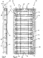
- FIG. 1 A first embodiment of a shroud is illustrated in an overall view of Figs. 1 to 5 .
- the shroud 10 substantially comprises a heat exchanger body 11 made of cast aluminum and a number of cooling ducts 12, a feeding duct 13 and a discharge duct 14.
- the feeding duct 13 forms a connecting piece 15 and a series of distribution ducts 16.
- Each cooling duct 12 is respectively connected to three distribution ducts 16, the distribution ducts 16 having a connection (not illustrated) to the connecting piece 15.
- the discharge duct 14 forms two collecting ducts 17, which in turn end in a common collecting duct section (not illustrated).
- the cooling ducts 12 are arranged parallel and in regular intervals in the heat exchanger body 11, the cooling ducts 12 being connected with their respective ends 18 on both sides to the collecting ducts 17.
- the ends 18 and the distribution ducts 16 protrude in sections out of a substantially plane and straight surface 19 of the rectangularly formed heat exchanger body 11.
- An opposite surface 20 of the heat exchanger body 11 faces a temperature room when the shroud 10 is installed in a temperature chamber (not illustrated).
- the shroud 10 comprises two electric heating elements 21 and 22, the electric heating elements 21 and 22 being substantially arranged in a common plane 23 with the cooling ducts 12 in the heat exchanger body 11.
- the electric heating elements 21 and 22 have a mantle 24 of stainless steel.
- the electric heating elements 21 and 22 are arranged or installed in a meandering fashion in the heat exchanger body 11.
- Element sections 25 of meanders 26 are arranged comparatively closely to the cooling ducts 12 so that a fast temperature change via a large temperature difference of electric heating elements 21 and 22 and of the cooling ducts 12 can be achieved due to the dense arrangement in sections.
- the heating elements 21 and 22 each have connections 27 and 28, respectively, which also protrude out of the surface 19 of the heat exchanger 11.
- Fig. 6 shows a schematic illustration of a temperature control device 29 inclduing the shroud 10.
- a temperature sensor 30 and a pressure sensor 31 are arranged both in the feeding duct 13 and in the discharge duct 14. Further, solenoid valves 32 and a manually operable valve 33 are arranged in the feeding duct 13.
- Liquid nitrogen (N 2 ) is introduced by a supply unit 34 via the feeding duct 13 into the shroud 10, a discharge taking place via the discharge duct 14. When the liquid nitrogen is introduced via the feeding duct 13, it is pressurized to approximately 2 bar. A blower for the nitrogen within the feeding duct 13 is not required.
- temperatures in a range of -196° C to +200° C can be generated.
- FIG. 7 and 8 An overall view of Figs. 7 and 8 shows a second embodiment of a shroud 35.
- the shroud 35 has a single cooling duct 36 with a direct connection to a feeding duct 37 and to a discharge duct 38.
- the cooling duct 36 runs in a parallel and meandering fashion within a heat exchanger body 39 made of cast aluminum.
- an electric heating element is arranged as well, which is not additionally illustrated here. Due to the described arrangement of the cooling duct 36, the shroud 35 can be formed in a particularly compact manner with the rectangular heat exchanger body 39.
Landscapes
- Engineering & Computer Science (AREA)
- Physics & Mathematics (AREA)
- Thermal Sciences (AREA)
- Mechanical Engineering (AREA)
- General Engineering & Computer Science (AREA)
- Remote Sensing (AREA)
- Aviation & Aerospace Engineering (AREA)
- Chemical & Material Sciences (AREA)
- Combustion & Propulsion (AREA)
- Heat-Exchange Devices With Radiators And Conduit Assemblies (AREA)
Claims (17)
- Élément (10, 35) de revêtement pour un dispositif (29) de régulation de température d'une chambre de température, ledit élément de revêtement pouvant être disposé dans une chambre de température, ledit élément de revêtement comprenant un conduit (13, 37) d'alimentation, un conduit (14, 38) de décharge et au moins un conduit (12, 36) de refroidissement pour un agent réfrigérant gazeux et/ou liquide, ledit conduit de refroidissement servant à refroidir la chambre de température et étant relié au conduit d'alimentation et au conduit de décharge, ledit élément de revêtement comprenant au moins un élément (21, 22) de chauffage électrique qui sert à chauffer la chambre de température, ledit élément de revêtement comprenant au moins un corps (11, 39) d'échangeur de chaleur pour refroidir et chauffer la chambre de température,
caractérisé en ce que
le conduit de refroidissement et l'élément de chauffage électrique sont disposés dans le corps d'échangeur de chaleur, ledit corps d'échangeur de chaleur étant fait en métal coulé dans lequel le conduit de refroidissement et l'élément de chauffage électrique sont disposés au moins partiellement. - Élément de revêtement selon la revendication 1,
caractérisé en ce que
le conduit (12, 36) de refroidissement et l'élément (21, 22) de chauffage électrique sont disposés dans une plane (23) commune dans le corps (11, 39) d'échangeur de chaleur. - Élément de revêtement selon la revendication 1 ou 2,
caractérisé en ce que
le conduit (12, 36) de refroidissement et l'élément (12, 22) de chauffage électrique sont coulés dans le corps (11, 39) d'échangeur de chaleur. - Élément de revêtement selon l'une quelconque des revendications précédentes,
caractérisé en ce que
le corps (11, 39) d'échangeur de chaleur se compose d'aluminium coulé ou d'alliage d'aluminium. - Élément de revêtement selon l'une quelconque des revendications précédentes,
caractérisé en ce que
l'agent réfrigérant est azote gazeux et/ou liquide. - Élément de revêtement selon l'une quelconque des revendications précédentes,
caractérisé en ce qu'
une pluralité de conduits (12, 36) de refroidissement sont formés. - Élément de revêtement selon l'une quelconque des revendications précédentes,
caractérisé en ce que
des conduits (12, 36) de refroidissement s'étendent dans le corps (11, 39) d'échangeur de chaleur dans une manière sinueuse et/ou parallèle. - Élément de revêtement selon l'une quelconque des revendications précédentes,
caractérisé en ce que
parmi le conduit (13, 37) d'alimentation, le conduit (14, 38) de décharge et le conduit (12, 36) de refroidissement, seulement le conduit (12, 36) de refroidissement s'étend dans le corps (11, 39) d'échangeur de chaleur. - Élément de revêtement selon l'une quelconque des revendications précédentes,
caractérisé en ce que
le conduit (13) d'alimentation forme une pluralité de conduits (16) de distribution et/ou le conduit (14) de décharge forme une pluralité de conduit (17) de collection. - Élément de revêtement selon la revendication 9,
caractérisé en ce qu'
un conduit (12) de refroidissement est relié à une pluralité de conduits (16) de distribution et/ou de conduits (17) de collection. - Élément de revêtement selon l'une quelconque des revendications précédentes,
caractérisé en ce que
le conduit (13, 37) d'alimentation, le conduit (14, 38) de décharge et le conduit (12, 36) de refroidissement sont fait en cuivre ou en acier inoxydable. - Élément de revêtement selon l'une quelconque des revendications précédentes,
caractérisé en ce qu'
une pluralité d'éléments (21, 22) de chauffage électriques sont disposés dans le corps (11, 39) d'échangeur de chaleur. - Élément de revêtement selon l'une quelconque des revendications précédentes,
caractérisé en ce que
l'élément (10, 35) de revêtement forme une forme en forme de plate, préférablement en forme rectangulaire, cylindrique ou, circulaire. - Chambre de température comprenant un dispositif (29) de régulation de température et au moins un élément (10, 35) de revêtement selon l'une quelconque des revendications précédentes.
- Procédé pour produire un élément (10, 35) de revêtement pour un dispositif (29) de régulation de température d'une chambre de température, ledit élément de revêtement pouvant être disposé dans une chambre de température, ledit élément de revêtement comprenant un conduit (13, 37) d'alimentation, un conduit (14, 38) de décharge et au moins un conduit (12, 36) de refroidissement pour un agent réfrigérant gazeux et/ou liquide, ledit conduit de refroidissement servant à refroidir la chambre de température et étant relié au conduit d'alimentation et au conduit de décharge, ledit élément de revêtement comprenant au moins un élément (21, 22) de chauffage électrique qui sert à chauffer la chambre de température, ledit élément de revêtement comprenant au moins un corps (11, 39) d'échangeur de chaleur pour refroidir et chauffer la chambre de température,
caractérisé en ce que
le conduit de refroidissement et l'élément de chauffage électrique sont disposés au moins partiellement dans une cavité d'un moule de coulée pour la formation du corps d'échangeur de chaleur, et du métal étant coulé dans la cavité. - Procédé selon la revendication 15,
caractérisé en ce que
le métal liquide est coulé au moyen d'un procédé de moulage sous pression. - Usage d'une élément (10, 35) de revêtement selon l'une quelconque des revendications 1 à 14 pour un dispositif (29) de régulation de température d'une chambre de température,
dans lequel
seulement l'azote (N2) liquide est alimenté dans le conduit (13, 37) d'alimentation de l'élément de revêtement.
Priority Applications (2)
| Application Number | Priority Date | Filing Date | Title |
|---|---|---|---|
| ES14001405.1T ES2654624T3 (es) | 2014-04-17 | 2014-04-17 | Protección para dispositivo de control de temperatura, procedimiento de fabricación del mismo y utilización de dicha protección |
| EP14001405.1A EP2933193B1 (fr) | 2014-04-17 | 2014-04-17 | Protection pour un dispositif de contrôle de température ainsi que procédé de fabrication et utilisation d'une telle protection |
Applications Claiming Priority (1)
| Application Number | Priority Date | Filing Date | Title |
|---|---|---|---|
| EP14001405.1A EP2933193B1 (fr) | 2014-04-17 | 2014-04-17 | Protection pour un dispositif de contrôle de température ainsi que procédé de fabrication et utilisation d'une telle protection |
Publications (2)
| Publication Number | Publication Date |
|---|---|
| EP2933193A1 EP2933193A1 (fr) | 2015-10-21 |
| EP2933193B1 true EP2933193B1 (fr) | 2017-10-18 |
Family
ID=50639250
Family Applications (1)
| Application Number | Title | Priority Date | Filing Date |
|---|---|---|---|
| EP14001405.1A Active EP2933193B1 (fr) | 2014-04-17 | 2014-04-17 | Protection pour un dispositif de contrôle de température ainsi que procédé de fabrication et utilisation d'une telle protection |
Country Status (2)
| Country | Link |
|---|---|
| EP (1) | EP2933193B1 (fr) |
| ES (1) | ES2654624T3 (fr) |
Families Citing this family (1)
| Publication number | Priority date | Publication date | Assignee | Title |
|---|---|---|---|---|
| JP6454452B1 (ja) * | 2017-09-06 | 2019-01-16 | 大陽日酸株式会社 | 宇宙環境試験装置および宇宙環境試験装置の初期冷却方法 |
Family Cites Families (6)
| Publication number | Priority date | Publication date | Assignee | Title |
|---|---|---|---|---|
| US3130562A (en) * | 1960-11-02 | 1964-04-28 | Gen Electric | Cryogenic pumping apparatus |
| NL135239C (fr) * | 1967-06-28 | |||
| JPS6026576B2 (ja) * | 1980-06-24 | 1985-06-24 | 株式会社東芝 | 熱真空チェンバの真空容器 |
| JP3069909B2 (ja) | 1990-10-18 | 2000-07-24 | 日本酸素株式会社 | 宇宙環境試験装置 |
| AU2001249376A1 (en) * | 2000-03-22 | 2001-10-15 | Chart Inc. | Novel space simulation chamber and method |
| EP2468486B1 (fr) * | 2010-12-23 | 2020-03-18 | Zehnder Group International AG | Procédé de fabrication d'un échangeur thermique |
-
2014
- 2014-04-17 EP EP14001405.1A patent/EP2933193B1/fr active Active
- 2014-04-17 ES ES14001405.1T patent/ES2654624T3/es active Active
Non-Patent Citations (1)
| Title |
|---|
| None * |
Also Published As
| Publication number | Publication date |
|---|---|
| EP2933193A1 (fr) | 2015-10-21 |
| ES2654624T3 (es) | 2018-02-14 |
Similar Documents
| Publication | Publication Date | Title |
|---|---|---|
| ES2254434T3 (es) | Camisa exterior termica para recipiente metalurgico. | |
| US9902089B2 (en) | Tool temperature control | |
| US20170089643A1 (en) | Heat Exchanger | |
| US9784503B2 (en) | Outer cooling loop | |
| US20160377327A1 (en) | Device for converting thermal energy | |
| WO2015030309A8 (fr) | Module de stockage au froid ayant une structure de grille métallique d'espacement inégal, conteneur frigorifique ayant des modules de stockage au froid installés dans celui-ci, et véhicule frigorifique | |
| CN105813771B (zh) | 旋压成型装置 | |
| EP2933193B1 (fr) | Protection pour un dispositif de contrôle de température ainsi que procédé de fabrication et utilisation d'une telle protection | |
| EP3749512B1 (fr) | Agencement de compression et procédé de refroidissement d'article dans ledit agencement | |
| CN105786045A (zh) | 高能系统的外置式环绕型温度控制装置及方法 | |
| US12479024B2 (en) | Method in a pressing arrangement | |
| EP4025416B1 (fr) | Procédé de commande de la vitesse de refroidissement dans un agencement de compression à chaud, module de commande et agencement de compression en lui-même | |
| CN112797664A (zh) | 包括不具有包含铁和硅和镧系元素的合金的磁致热材料的整体部件和包括该部件的热发生器 | |
| US20180164003A1 (en) | Temperature Control Unit for Gaseous or Liquid Medium | |
| CN110678319B (zh) | 压制设备 | |
| JPH0674688A (ja) | 特に腐食性流体のための熱交換器 | |
| HK1212013A1 (en) | One-piece part including a magnetocaloric material including an alloy including iron and silicon and at least one lanthanide, and method for manufacturing said one-piece part | |
| CN103402746B (zh) | 非均匀缸 | |
| CN203236084U (zh) | 一种气热钎焊设备 | |
| WO2012149979A1 (fr) | Montage pour pressage | |
| EP3749511B1 (fr) | Procédé de traitement d'articles et procédé de traitement haute pression d'articles | |
| CN102927091A (zh) | 管路油液加热器 | |
| WO2013110938A2 (fr) | Génératrice pour refroidisseur à absorption et refroidisseur à absorption comprenant une telle génératrice | |
| CN106235367A (zh) | 一种采用多段式加热的粮食加工装置 |
Legal Events
| Date | Code | Title | Description |
|---|---|---|---|
| PUAI | Public reference made under article 153(3) epc to a published international application that has entered the european phase |
Free format text: ORIGINAL CODE: 0009012 |
|
| AK | Designated contracting states |
Kind code of ref document: A1 Designated state(s): AL AT BE BG CH CY CZ DE DK EE ES FI FR GB GR HR HU IE IS IT LI LT LU LV MC MK MT NL NO PL PT RO RS SE SI SK SM TR |
|
| AX | Request for extension of the european patent |
Extension state: BA ME |
|
| RAP1 | Party data changed (applicant data changed or rights of an application transferred) |
Owner name: WEISS UMWELTTECHNIK GMBH |
|
| 17P | Request for examination filed |
Effective date: 20160324 |
|
| RBV | Designated contracting states (corrected) |
Designated state(s): AL AT BE BG CH CY CZ DE DK EE ES FI FR GB GR HR HU IE IS IT LI LT LU LV MC MK MT NL NO PL PT RO RS SE SI SK SM TR |
|
| RIC1 | Information provided on ipc code assigned before grant |
Ipc: B64G 7/00 20060101AFI20170403BHEP Ipc: F28F 3/12 20060101ALI20170403BHEP Ipc: F28D 1/047 20060101ALI20170403BHEP Ipc: F28D 21/00 20060101ALI20170403BHEP Ipc: F28F 1/32 20060101ALI20170403BHEP Ipc: F28D 1/053 20060101ALI20170403BHEP Ipc: F28F 21/08 20060101ALI20170403BHEP Ipc: F25D 3/10 20060101ALI20170403BHEP |
|
| GRAP | Despatch of communication of intention to grant a patent |
Free format text: ORIGINAL CODE: EPIDOSNIGR1 |
|
| STAA | Information on the status of an ep patent application or granted ep patent |
Free format text: STATUS: GRANT OF PATENT IS INTENDED |
|
| INTG | Intention to grant announced |
Effective date: 20170530 |
|
| GRAS | Grant fee paid |
Free format text: ORIGINAL CODE: EPIDOSNIGR3 |
|
| GRAA | (expected) grant |
Free format text: ORIGINAL CODE: 0009210 |
|
| STAA | Information on the status of an ep patent application or granted ep patent |
Free format text: STATUS: THE PATENT HAS BEEN GRANTED |
|
| AK | Designated contracting states |
Kind code of ref document: B1 Designated state(s): AL AT BE BG CH CY CZ DE DK EE ES FI FR GB GR HR HU IE IS IT LI LT LU LV MC MK MT NL NO PL PT RO RS SE SI SK SM TR |
|
| REG | Reference to a national code |
Ref country code: GB Ref legal event code: FG4D |
|
| REG | Reference to a national code |
Ref country code: CH Ref legal event code: EP |
|
| REG | Reference to a national code |
Ref country code: AT Ref legal event code: REF Ref document number: 937701 Country of ref document: AT Kind code of ref document: T Effective date: 20171115 Ref country code: IE Ref legal event code: FG4D |
|
| REG | Reference to a national code |
Ref country code: DE Ref legal event code: R096 Ref document number: 602014015843 Country of ref document: DE |
|
| REG | Reference to a national code |
Ref country code: ES Ref legal event code: FG2A Ref document number: 2654624 Country of ref document: ES Kind code of ref document: T3 Effective date: 20180214 |
|
| REG | Reference to a national code |
Ref country code: NL Ref legal event code: MP Effective date: 20171018 |
|
| REG | Reference to a national code |
Ref country code: LT Ref legal event code: MG4D |
|
| REG | Reference to a national code |
Ref country code: AT Ref legal event code: MK05 Ref document number: 937701 Country of ref document: AT Kind code of ref document: T Effective date: 20171018 |
|
| PG25 | Lapsed in a contracting state [announced via postgrant information from national office to epo] |
Ref country code: NL Free format text: LAPSE BECAUSE OF FAILURE TO SUBMIT A TRANSLATION OF THE DESCRIPTION OR TO PAY THE FEE WITHIN THE PRESCRIBED TIME-LIMIT Effective date: 20171018 |
|
| PG25 | Lapsed in a contracting state [announced via postgrant information from national office to epo] |
Ref country code: FI Free format text: LAPSE BECAUSE OF FAILURE TO SUBMIT A TRANSLATION OF THE DESCRIPTION OR TO PAY THE FEE WITHIN THE PRESCRIBED TIME-LIMIT Effective date: 20171018 Ref country code: SE Free format text: LAPSE BECAUSE OF FAILURE TO SUBMIT A TRANSLATION OF THE DESCRIPTION OR TO PAY THE FEE WITHIN THE PRESCRIBED TIME-LIMIT Effective date: 20171018 Ref country code: NO Free format text: LAPSE BECAUSE OF FAILURE TO SUBMIT A TRANSLATION OF THE DESCRIPTION OR TO PAY THE FEE WITHIN THE PRESCRIBED TIME-LIMIT Effective date: 20180118 Ref country code: LT Free format text: LAPSE BECAUSE OF FAILURE TO SUBMIT A TRANSLATION OF THE DESCRIPTION OR TO PAY THE FEE WITHIN THE PRESCRIBED TIME-LIMIT Effective date: 20171018 |
|
| REG | Reference to a national code |
Ref country code: FR Ref legal event code: PLFP Year of fee payment: 5 |
|
| PG25 | Lapsed in a contracting state [announced via postgrant information from national office to epo] |
Ref country code: BG Free format text: LAPSE BECAUSE OF FAILURE TO SUBMIT A TRANSLATION OF THE DESCRIPTION OR TO PAY THE FEE WITHIN THE PRESCRIBED TIME-LIMIT Effective date: 20180118 Ref country code: AT Free format text: LAPSE BECAUSE OF FAILURE TO SUBMIT A TRANSLATION OF THE DESCRIPTION OR TO PAY THE FEE WITHIN THE PRESCRIBED TIME-LIMIT Effective date: 20171018 Ref country code: HR Free format text: LAPSE BECAUSE OF FAILURE TO SUBMIT A TRANSLATION OF THE DESCRIPTION OR TO PAY THE FEE WITHIN THE PRESCRIBED TIME-LIMIT Effective date: 20171018 Ref country code: LV Free format text: LAPSE BECAUSE OF FAILURE TO SUBMIT A TRANSLATION OF THE DESCRIPTION OR TO PAY THE FEE WITHIN THE PRESCRIBED TIME-LIMIT Effective date: 20171018 Ref country code: IS Free format text: LAPSE BECAUSE OF FAILURE TO SUBMIT A TRANSLATION OF THE DESCRIPTION OR TO PAY THE FEE WITHIN THE PRESCRIBED TIME-LIMIT Effective date: 20180218 Ref country code: RS Free format text: LAPSE BECAUSE OF FAILURE TO SUBMIT A TRANSLATION OF THE DESCRIPTION OR TO PAY THE FEE WITHIN THE PRESCRIBED TIME-LIMIT Effective date: 20171018 Ref country code: GR Free format text: LAPSE BECAUSE OF FAILURE TO SUBMIT A TRANSLATION OF THE DESCRIPTION OR TO PAY THE FEE WITHIN THE PRESCRIBED TIME-LIMIT Effective date: 20180119 |
|
| REG | Reference to a national code |
Ref country code: DE Ref legal event code: R097 Ref document number: 602014015843 Country of ref document: DE |
|
| PG25 | Lapsed in a contracting state [announced via postgrant information from national office to epo] |
Ref country code: CZ Free format text: LAPSE BECAUSE OF FAILURE TO SUBMIT A TRANSLATION OF THE DESCRIPTION OR TO PAY THE FEE WITHIN THE PRESCRIBED TIME-LIMIT Effective date: 20171018 Ref country code: EE Free format text: LAPSE BECAUSE OF FAILURE TO SUBMIT A TRANSLATION OF THE DESCRIPTION OR TO PAY THE FEE WITHIN THE PRESCRIBED TIME-LIMIT Effective date: 20171018 Ref country code: DK Free format text: LAPSE BECAUSE OF FAILURE TO SUBMIT A TRANSLATION OF THE DESCRIPTION OR TO PAY THE FEE WITHIN THE PRESCRIBED TIME-LIMIT Effective date: 20171018 Ref country code: SK Free format text: LAPSE BECAUSE OF FAILURE TO SUBMIT A TRANSLATION OF THE DESCRIPTION OR TO PAY THE FEE WITHIN THE PRESCRIBED TIME-LIMIT Effective date: 20171018 |
|
| PLBE | No opposition filed within time limit |
Free format text: ORIGINAL CODE: 0009261 |
|
| STAA | Information on the status of an ep patent application or granted ep patent |
Free format text: STATUS: NO OPPOSITION FILED WITHIN TIME LIMIT |
|
| PG25 | Lapsed in a contracting state [announced via postgrant information from national office to epo] |
Ref country code: SM Free format text: LAPSE BECAUSE OF FAILURE TO SUBMIT A TRANSLATION OF THE DESCRIPTION OR TO PAY THE FEE WITHIN THE PRESCRIBED TIME-LIMIT Effective date: 20171018 Ref country code: RO Free format text: LAPSE BECAUSE OF FAILURE TO SUBMIT A TRANSLATION OF THE DESCRIPTION OR TO PAY THE FEE WITHIN THE PRESCRIBED TIME-LIMIT Effective date: 20171018 Ref country code: PL Free format text: LAPSE BECAUSE OF FAILURE TO SUBMIT A TRANSLATION OF THE DESCRIPTION OR TO PAY THE FEE WITHIN THE PRESCRIBED TIME-LIMIT Effective date: 20171018 |
|
| 26N | No opposition filed |
Effective date: 20180719 |
|
| PG25 | Lapsed in a contracting state [announced via postgrant information from national office to epo] |
Ref country code: MC Free format text: LAPSE BECAUSE OF FAILURE TO SUBMIT A TRANSLATION OF THE DESCRIPTION OR TO PAY THE FEE WITHIN THE PRESCRIBED TIME-LIMIT Effective date: 20171018 Ref country code: SI Free format text: LAPSE BECAUSE OF FAILURE TO SUBMIT A TRANSLATION OF THE DESCRIPTION OR TO PAY THE FEE WITHIN THE PRESCRIBED TIME-LIMIT Effective date: 20171018 |
|
| REG | Reference to a national code |
Ref country code: CH Ref legal event code: PL |
|
| REG | Reference to a national code |
Ref country code: BE Ref legal event code: MM Effective date: 20180430 |
|
| REG | Reference to a national code |
Ref country code: IE Ref legal event code: MM4A |
|
| PG25 | Lapsed in a contracting state [announced via postgrant information from national office to epo] |
Ref country code: LU Free format text: LAPSE BECAUSE OF NON-PAYMENT OF DUE FEES Effective date: 20180417 |
|
| PG25 | Lapsed in a contracting state [announced via postgrant information from national office to epo] |
Ref country code: LI Free format text: LAPSE BECAUSE OF NON-PAYMENT OF DUE FEES Effective date: 20180430 Ref country code: BE Free format text: LAPSE BECAUSE OF NON-PAYMENT OF DUE FEES Effective date: 20180430 Ref country code: CH Free format text: LAPSE BECAUSE OF NON-PAYMENT OF DUE FEES Effective date: 20180430 |
|
| PG25 | Lapsed in a contracting state [announced via postgrant information from national office to epo] |
Ref country code: IE Free format text: LAPSE BECAUSE OF NON-PAYMENT OF DUE FEES Effective date: 20180417 |
|
| PG25 | Lapsed in a contracting state [announced via postgrant information from national office to epo] |
Ref country code: MT Free format text: LAPSE BECAUSE OF NON-PAYMENT OF DUE FEES Effective date: 20180417 |
|
| PG25 | Lapsed in a contracting state [announced via postgrant information from national office to epo] |
Ref country code: TR Free format text: LAPSE BECAUSE OF FAILURE TO SUBMIT A TRANSLATION OF THE DESCRIPTION OR TO PAY THE FEE WITHIN THE PRESCRIBED TIME-LIMIT Effective date: 20171018 |
|
| PG25 | Lapsed in a contracting state [announced via postgrant information from national office to epo] |
Ref country code: PT Free format text: LAPSE BECAUSE OF FAILURE TO SUBMIT A TRANSLATION OF THE DESCRIPTION OR TO PAY THE FEE WITHIN THE PRESCRIBED TIME-LIMIT Effective date: 20171018 |
|
| PG25 | Lapsed in a contracting state [announced via postgrant information from national office to epo] |
Ref country code: CY Free format text: LAPSE BECAUSE OF FAILURE TO SUBMIT A TRANSLATION OF THE DESCRIPTION OR TO PAY THE FEE WITHIN THE PRESCRIBED TIME-LIMIT Effective date: 20171018 Ref country code: HU Free format text: LAPSE BECAUSE OF FAILURE TO SUBMIT A TRANSLATION OF THE DESCRIPTION OR TO PAY THE FEE WITHIN THE PRESCRIBED TIME-LIMIT; INVALID AB INITIO Effective date: 20140417 Ref country code: MK Free format text: LAPSE BECAUSE OF NON-PAYMENT OF DUE FEES Effective date: 20171018 |
|
| PG25 | Lapsed in a contracting state [announced via postgrant information from national office to epo] |
Ref country code: AL Free format text: LAPSE BECAUSE OF FAILURE TO SUBMIT A TRANSLATION OF THE DESCRIPTION OR TO PAY THE FEE WITHIN THE PRESCRIBED TIME-LIMIT Effective date: 20171018 |
|
| P01 | Opt-out of the competence of the unified patent court (upc) registered |
Effective date: 20230524 |
|
| PGFP | Annual fee paid to national office [announced via postgrant information from national office to epo] |
Ref country code: ES Payment date: 20240516 Year of fee payment: 11 |
|
| PGFP | Annual fee paid to national office [announced via postgrant information from national office to epo] |
Ref country code: DE Payment date: 20250428 Year of fee payment: 12 |
|
| PGFP | Annual fee paid to national office [announced via postgrant information from national office to epo] |
Ref country code: GB Payment date: 20250422 Year of fee payment: 12 |
|
| PGFP | Annual fee paid to national office [announced via postgrant information from national office to epo] |
Ref country code: IT Payment date: 20250422 Year of fee payment: 12 |
|
| PGFP | Annual fee paid to national office [announced via postgrant information from national office to epo] |
Ref country code: FR Payment date: 20250424 Year of fee payment: 12 |