EP2933238B1 - Procédé de fabrication d'une préforme de fibre optique à coeur non circulaire et manteau dopé, ayant une ouverture numérique donnée - Google Patents
Procédé de fabrication d'une préforme de fibre optique à coeur non circulaire et manteau dopé, ayant une ouverture numérique donnée Download PDFInfo
- Publication number
- EP2933238B1 EP2933238B1 EP15163788.1A EP15163788A EP2933238B1 EP 2933238 B1 EP2933238 B1 EP 2933238B1 EP 15163788 A EP15163788 A EP 15163788A EP 2933238 B1 EP2933238 B1 EP 2933238B1
- Authority
- EP
- European Patent Office
- Prior art keywords
- core
- dopant concentration
- parameter
- blank
- section
- Prior art date
- Legal status (The legal status is an assumption and is not a legal conclusion. Google has not performed a legal analysis and makes no representation as to the accuracy of the status listed.)
- Active
Links
Images
Classifications
-
- C—CHEMISTRY; METALLURGY
- C03—GLASS; MINERAL OR SLAG WOOL
- C03B—MANUFACTURE, SHAPING, OR SUPPLEMENTARY PROCESSES
- C03B37/00—Manufacture or treatment of flakes, fibres, or filaments from softened glass, minerals, or slags
- C03B37/01—Manufacture of glass fibres or filaments
- C03B37/012—Manufacture of preforms for drawing fibres or filaments
- C03B37/01205—Manufacture of preforms for drawing fibres or filaments starting from tubes, rods, fibres or filaments
- C03B37/01211—Manufacture of preforms for drawing fibres or filaments starting from tubes, rods, fibres or filaments by inserting one or more rods or tubes into a tube
-
- G—PHYSICS
- G02—OPTICS
- G02B—OPTICAL ELEMENTS, SYSTEMS OR APPARATUS
- G02B6/00—Light guides; Structural details of arrangements comprising light guides and other optical elements, e.g. couplings
- G02B6/02—Optical fibres with cladding with or without a coating
-
- C—CHEMISTRY; METALLURGY
- C03—GLASS; MINERAL OR SLAG WOOL
- C03B—MANUFACTURE, SHAPING, OR SUPPLEMENTARY PROCESSES
- C03B2201/00—Type of glass produced
- C03B2201/06—Doped silica-based glasses
- C03B2201/08—Doped silica-based glasses doped with boron or fluorine or other refractive index decreasing dopant
- C03B2201/10—Doped silica-based glasses doped with boron or fluorine or other refractive index decreasing dopant doped with boron
-
- C—CHEMISTRY; METALLURGY
- C03—GLASS; MINERAL OR SLAG WOOL
- C03B—MANUFACTURE, SHAPING, OR SUPPLEMENTARY PROCESSES
- C03B2201/00—Type of glass produced
- C03B2201/06—Doped silica-based glasses
- C03B2201/08—Doped silica-based glasses doped with boron or fluorine or other refractive index decreasing dopant
- C03B2201/12—Doped silica-based glasses doped with boron or fluorine or other refractive index decreasing dopant doped with fluorine
-
- C—CHEMISTRY; METALLURGY
- C03—GLASS; MINERAL OR SLAG WOOL
- C03B—MANUFACTURE, SHAPING, OR SUPPLEMENTARY PROCESSES
- C03B2201/00—Type of glass produced
- C03B2201/06—Doped silica-based glasses
- C03B2201/20—Doped silica-based glasses doped with non-metals other than boron or fluorine
- C03B2201/28—Doped silica-based glasses doped with non-metals other than boron or fluorine doped with phosphorus
-
- C—CHEMISTRY; METALLURGY
- C03—GLASS; MINERAL OR SLAG WOOL
- C03B—MANUFACTURE, SHAPING, OR SUPPLEMENTARY PROCESSES
- C03B2201/00—Type of glass produced
- C03B2201/06—Doped silica-based glasses
- C03B2201/30—Doped silica-based glasses doped with metals, e.g. Ga, Sn, Sb, Pb or Bi
- C03B2201/31—Doped silica-based glasses doped with metals, e.g. Ga, Sn, Sb, Pb or Bi doped with germanium
-
- C—CHEMISTRY; METALLURGY
- C03—GLASS; MINERAL OR SLAG WOOL
- C03B—MANUFACTURE, SHAPING, OR SUPPLEMENTARY PROCESSES
- C03B2201/00—Type of glass produced
- C03B2201/06—Doped silica-based glasses
- C03B2201/30—Doped silica-based glasses doped with metals, e.g. Ga, Sn, Sb, Pb or Bi
- C03B2201/32—Doped silica-based glasses doped with metals, e.g. Ga, Sn, Sb, Pb or Bi doped with aluminium
-
- C—CHEMISTRY; METALLURGY
- C03—GLASS; MINERAL OR SLAG WOOL
- C03B—MANUFACTURE, SHAPING, OR SUPPLEMENTARY PROCESSES
- C03B2201/00—Type of glass produced
- C03B2201/06—Doped silica-based glasses
- C03B2201/30—Doped silica-based glasses doped with metals, e.g. Ga, Sn, Sb, Pb or Bi
- C03B2201/34—Doped silica-based glasses doped with metals, e.g. Ga, Sn, Sb, Pb or Bi doped with rare earth metals, i.e. with Sc, Y or lanthanides, e.g. for laser-amplifiers
-
- C—CHEMISTRY; METALLURGY
- C03—GLASS; MINERAL OR SLAG WOOL
- C03B—MANUFACTURE, SHAPING, OR SUPPLEMENTARY PROCESSES
- C03B2203/00—Fibre product details, e.g. structure, shape
- C03B2203/10—Internal structure or shape details
- C03B2203/12—Non-circular or non-elliptical cross-section, e.g. planar core
-
- H—ELECTRICITY
- H01—ELECTRIC ELEMENTS
- H01S—DEVICES USING THE PROCESS OF LIGHT AMPLIFICATION BY STIMULATED EMISSION OF RADIATION [LASER] TO AMPLIFY OR GENERATE LIGHT; DEVICES USING STIMULATED EMISSION OF ELECTROMAGNETIC RADIATION IN WAVE RANGES OTHER THAN OPTICAL
- H01S3/00—Lasers, i.e. devices using stimulated emission of electromagnetic radiation in the infrared, visible or ultraviolet wave range
- H01S3/05—Construction or shape of optical resonators; Accommodation of active medium therein; Shape of active medium
- H01S3/06—Construction or shape of active medium
- H01S3/063—Waveguide lasers, i.e. whereby the dimensions of the waveguide are of the order of the light wavelength
- H01S3/067—Fibre lasers
- H01S3/06708—Constructional details of the fibre, e.g. compositions, cross-section, shape or tapering
- H01S3/06712—Polarising fibre; Polariser
Definitions
- the height of the NA of an optical waveguide can in principle be adjusted by the refractive index difference between the core region and the cladding region. For round nuclei, it is possible to calculate the NA of the optical waveguide from this refractive index difference. If, for example, an undoped core material is used and the cladding region is to be doped with fluorine, the required concentration of fluorine in the cladding region can be calculated from the required refractive index difference and adjusted during production of the preform.
- the DE 10 2009 004 756 A1 describes a method in which a rectangular core rod is enclosed with a jacket tube. As a result, the thermal load is reduced and improved angularity is obtained.
- a most homogeneous dopant concentration in the cladding region is achieved by depositing a first cladding layer for filling the valley regions between the corners under first deposition conditions. Thereafter, the preform is ground round and prepared for the deposition of the second cladding layer. This is then applied under deposition conditions which may be identical to the first, but not have to. It is designed so that the dopant concentration in the second cladding layer is identical to the first cladding layer.
- a nominal dopant concentration is set for the production of the jacket region.
- the nominal dopant concentration is determined from the effective dopant concentration as a function of parameters that describe the fiber structure of the optical waveguide. These parameters are the intended core geometry of the optical waveguide and / or mechanical parameters of the fiber structure of the optical waveguide to be manufactured.
- the preform core is produced with the intended geometry of the cross section of the preform. Subsequently, the preforming core is surrounded by a cladding region with the nominal dopant concentration.
- the effective dopant concentration c eff and the nominal dopant concentration c nom and the scaling factor F are linked according to the invention via the following relationship: c eff ⁇ F ⁇ c nom .
- the scaling factor F with a parameter set V, C, S and N on the relationship F V ⁇ 1 + C - 1 ⁇ N ⁇ 1 + S - 1 ⁇ N calculated.
- V is a measure of a corner fillet
- C describes an influence of a coating of the optical waveguide
- N is a corner number of the core
- S describes an influence of a barrier layer.
- the nominal dopant concentration is increased compared to the effective dopant concentration, and an evaluation of a parameter describing a corner rounding V of the non-round cross-section is performed to determine the degree of increase of the effective dopant concentration to the nominal dopant concentration.
- the nominal dopant concentration is increased compared to the effective dopant concentration, with the Increase of the dopant concentration in addition to the parameter of the corner fillet V is determined from a number of corners N and from the parameters C and S, which describe an influence of a proposed coating (parameter C) and a barrier layer (parameter S).
- the nominal dopant concentration is increased compared to the effective dopant concentration, with the Increase of the dopant concentration in addition to the parameter of the corner fillet V is determined from a number of corners N and from the parameters C and S, which describe an influence of a proposed coating (parameter C) and a barrier layer (parameter S).
- the parameter S of the influence of the barrier layer is determined in an expedient embodiment of the method of the thermal expansion coefficient CTE S of the material of the barrier layer and the thermal expansion coefficient CTE C of the cladding of the optical waveguide to be produced.
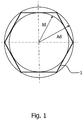
- the parameter V of the corner fillet results in one embodiment of the method of three descriptive characteristics, namely an outside diameter Ad describing the non-round cross section, an inside diameter Id inscribed in the non-round cross section and a corner number N of the non-round core.
- a cladding region with a cladding cross-section adapted to the cross-sectional geometry of the preform core is applied such that the core-cladding ratio is constant over the entire cross-section of the preform.
- the constant core-to-shell ratio throughout the entire cross-section of the preform implies that also the cladding region of the preform has a cross-section at least similar to that of the core of the preform. This means, in particular, that the cross section of the cladding region is also non-round.
- the preform core is manufactured in the required cross-sectional geometry, wherein subsequently a Aufkollabieren a jacket tube with the nominal dopant concentration. This makes it possible in particular the mentioned constant Realizing the core-sheath ratio particularly easy over the preform cross-section.
- Fluorine or a fluorine compound is provided in particular as dopant. This lowers the refractive index of the cladding region.
- the cladding layer of the preform has a nominal dopant concentration which is increased compared to an effective dopant concentration of a preform for a round core geometry optical fiber having an identical numerical aperture.
- the nominal dopant concentration is in particular greater than or equal to the effective dopant concentration multiplied by a geometric correction factor describing at least the cross-sectional shape of the core.
- the ratio of the core diameter to the diameter of the stress-generating jacket region is greater than 2.5, preferably greater than 4 and particularly preferably greater than 5.8.
- a square core rod is surrounded by a fluorine-doped cladding layer.
- the fluorine concentration is adjusted in such a way that a numerical aperture of 0.20 is to be expected on a round core geometry.
- the fiber draw at the initial stage is selected to be at a high draw temperature such that an almost circular fiber is drawn from the quadratic preform due to the surface tension.
- An NA measurement on this fiber confirmed the target value of 0.20.
- an NA of 0.16 was achieved.
- the nominal dopant concentration of the cladding region is represented by a nominal fluorine concentration.
- the following explanations are then transferable to other dopants in the context of expert action.
- a fluorine concentration is thus determined which compensates for the NA-lowering effects of the optical waveguide geometry and thus results in the desired NA at the final optical waveguide.
- the parameters used are mainly the number of corners, the corner rounding and stresses generated by further cladding layers.
- a numerical aperture for the optical waveguide is given, this is converted accordingly into the effective fluorine concentration and from this the nominal fluorine concentration can then be determined depending on the design of the optical waveguide.
- This nominal fluorine concentration is used as a default during manufacturing.
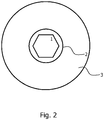
- Fig. 2 shows, for example, a design with a core 1, a jacket 2 and a barrier layer 3.
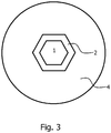
- Fig. 3 shows a structure with a core 1, a jacket 2 and a surrounding coating 4.
- the jacket is referred to in the following versions as cladding. In the following explanations, reference is made to the respective figures.
- F V ⁇ 1 + C - 1 ⁇ N ⁇ 1 + S - 1 ⁇ N
- Ad describes the outer diameter of the circle described in the N-corner.
- Id describes the inner diameter of the circle inscribed in the N-corner.
- the parameter of the corner fillet V is a measure of how much the achieved shape of the non-round fiber core deviates from the ideal shape of a polygon and merges into that of a circle.
- the corner fillet is identical to zero, and increasing values for V indicate that the ideal polygon shape is increasingly merging into that of a circle, with the sides of the polygon in particular becoming increasingly arcuate.
- the jacket layer thickness can be optimized by a non-circular shell geometry. If a round sheath layer becomes a 6-cornered core geometry, the so-called clad to core diameter ratio inevitably changes.
- the shell geometry is adapted to the core geometry.
- An example is in this Fig. 3 shown. Shown here is a structure of a core 1, a cladding 2 and a surrounding coating 4. If a 6-sided jacket 2 is applied to the 6-cornered core, the CCDR is the same size at all points and the material cost considerably less.
- a non-circular shell geometry can also prove to be advantageous if the fibers are to be further processed into fiber bundles later, because thus the gaps between individual fibers in the bundle production can be significantly reduced. This results in better processability during bundle production. Since hardly any hollow spaces available In addition, the fiber geometry is much better preserved when many single fibers merge into a bundle.
- fiber bundles and fibers which are particularly stable against electromagnetic radiation by a suitable choice of the core and sheath materials and optimized process conditions.
- a resistance to ultraviolet or higher energy radiation such as X-rays or gamma radiation is set.
- a square core rod was surrounded with a fluorine-doped cladding layer.
- the fluorine concentration was adjusted in such a way that a numerical aperture of 0.20 was achieved on a round core geometry.
- this preform was warped into a fiber, the fiber draw was so high in the initial range that a nearly circular fiber was drawn due to the surface tension of the square preform.
- An NA measurement on this fiber confirmed the target value of 0.20.
- warping the preform with reduced draw temperature and maintaining the non-round core geometry an NA of 0.16 was achieved. It follows that the corner rounding of the preform during fiber drawing need not necessarily be preserved. Due to high drawing temperatures, the corner rounding can be increased.
- An essential parameter for achieving this transmission improvement is the reduction of the pulling speed.
- the slower the fiber is pulled the slower the fiber cools and thus increases the duration at which structural defects in the glass structure can heal. Due to the slow pulling speed, the duration of stay in hot Ziehofen is increased, so that even here can already take place defects.
- the fibers with non-round cores can be used as single fibers, but also a use in fiber bundles is possible.
- the jacket is formed in a polygonal shape.
- the packing density of fiber bundles with non-circular outer geometries is higher compared to round fibers. As a result, the light-conducting surface is also increased and the bundle has a smaller proportion of non-light-conducting regions.
- a rectangular core is used.
- the aspect ratios can be chosen freely. However, there are certain limits that depend on the manufacturing process used. If the cladding layer is applied using a jacketing method, the geometry of the jacketing tube is determined as a function of the aspect ratio. The larger the aspect ratio is, the more oval the pipe is made to have the most even gap between the pipe and the pipe To comply with the preform.
- the inner geometry of the tube is adapted to the outer geometry of the substrate. In this case, for example, tubes are produced with polygonal internal geometries and these alskollabiert on corresponding substrates. The gap dimensions between the substrate and the tube are almost identical over the entire substrate circumference, so that no material shifts or bubbles occur in the interface during jacketing.
- the cladding is produced with two different refractive indices, so that an inner and an outer cladding arises.
- the inner cladding has a higher refractive index than the outer cladding, both refractive indices being smaller than the core refractive index.
- the numerical aperture can be selectively influenced and adjusted.
- the layer thickness of the inner cladding can also be used to enhance or weaken the effect of the inner cladding.
- a mother substrate can be made with an internal cladding and then provided with a second outer cladding depending on the desired numerical aperture on the final product, so that the desired parameters are obtained on the final product.
- a mother substrate that can be used for different target values, the manufacturing effort and time is significantly reduced. It can also be used for the production of the mother substrate on very large substrates, which minimizes the processing costs, for example, caused by grinding or polishing the surface, in relation to the mass of the final product.
- the increased freedom of design of the preform made possible by the second cladding does not require the complete master rod for one specific product design are used. Rather, first a larger series can be made, are separated from the smaller, specially designed subsets for different end products and separately processed separately.
- the concepts mentioned in the exemplary embodiments are not restricted to special outer diameters of the semifinished product or end product.
- the preforms may have diameters greater than 15 mm, preferably a range of 20 to 50 mm, and more preferably a range of between 25 and 35 mm. In this diameter range, the necessary processing steps can be performed at lower temperatures compared to much thicker preforms. This has proven to be advantageous for maintaining the angularity of the core area.
- the fibers from the preforms described here generally have outer diameters of up to 1200 .mu.m, a diameter range of from 75 to 600 .mu.m being preferred and a range of between 200 and 500 .mu.m being particularly preferred.
- preforms can also be drawn or stretched to larger diameters, so that the end product is not a fiber but a light-conducting rod. Diameters of 1.2 to 15 mm are possible, the range between 2 and 6 mm being preferred, and the range between 2.5 and 3.5 mm being particularly preferred.
Landscapes
- Physics & Mathematics (AREA)
- Engineering & Computer Science (AREA)
- Chemical & Material Sciences (AREA)
- General Physics & Mathematics (AREA)
- Optics & Photonics (AREA)
- Life Sciences & Earth Sciences (AREA)
- General Life Sciences & Earth Sciences (AREA)
- Geochemistry & Mineralogy (AREA)
- Manufacturing & Machinery (AREA)
- Materials Engineering (AREA)
- Organic Chemistry (AREA)
- Manufacture, Treatment Of Glass Fibers (AREA)
Claims (9)
- Procédé de fabrication d'une préforme pour un guide optique présentant une ouverture numérique donnée, comportant une zone enveloppe et un âme de préforme à section transversale polygonale, comprenant les étapes consistant à- détecter une concentration effective de dopants de la zone enveloppe pour le guide optique à fabriquer à partir de l'ouverture numérique donnée,- régler une concentration nominale de dopants lors de la fabrication de la zone enveloppe, la concentration nominale de dopants étant calculée à partir de la concentration effective de dopants en fonction de paramètres géométriques décrivant la structure de fibres du guide optique, en particulier en fonction d'une géométrie d'âme prévue du guide optique et/ou en fonction de paramètres mécaniques de la structure de fibres du guide optique à fabriquer,- réaliser l'âme de la préforme avec la géométrie prévue de la section transversale de l'âme de la préforme,- entourer l'âme de la préforme par une zone enveloppe de la préforme avec la concentration nominale de dopants,caractérisé en ce que
la concentration effective de dopants ceff et la concentration nominale de dopants cnom et le facteur d'échelle F sont liés par la relation suivante :

- Procédé selon la revendication 1,
caractérisé en ce que
on augmente la concentration nominale de dopants par comparaison à la concentration effective de dopants, et pour déterminer le degré de l'augmentation de la concentration effective de dopants pour passer à la concentration nominale de dopants, on effectue une évaluation d'un paramètre qui décrit un arrondi d'angle V de la section transversale polygonale. - Procédé selon la revendication 1,
caractérisé en ce que
la concentration nominale de dopants est augmentée par comparaison à la concentration effective de dopants, et l'augmentation de la concentration de dopants est définie en supplément au paramètre de l'arrondi d'angle V, à partir d'un nombre d'angles N ainsi que d'un paramètre C qui décrit une influence d'un revêtement prévu et d'un paramètre S qui décrit une influence d'une couche de barrière. - Procédé selon la revendication 3,
caractérisé en ce que
on définit le paramètre S de l'influence de la couche de barrière à partir des coefficients de dilatation thermiques CTEs du matériau de la couche de barrière et du coefficient de dilatation thermique CTEC du gainage du guide optique à fabriquer. - Procédé selon la revendication 2,
caractérisé en ce que
on définit le paramètre V de l'arrondi d'angle à partir d'un diamètre extérieur Ad inscrivant la section transversale polygonale, d'un diamètre intérieur Id inscrit dans la section transversale polygonale et d'un nombre d'angles N. - Procédé selon l'une des revendications précédentes,
caractérisé en ce que
lors de la fabrication de la préforme, on applique sur l'âme polygonale de la préforme une zone enveloppe présentant une section transversale d'enveloppe adaptée à la géométrie de section transversale de l'âme de la préforme, de telle sorte que le rapport âme/enveloppe est constant sur toute la section transversale de la préforme. - Procédé selon la revendication 6,
caractérisé en ce que
on fabrique l'âme de la préforme dans la géométrie requise de la section transversale, et à la suite on procède à un affaissement d'un tube enveloppe avec la concentration nominale de dopants. - Procédé selon l'une des revendications précédentes,
caractérisé en ce que
on prévoit en tant que dopant du fluore ou un composé fluoré. - Procédé selon la revendication 1,
caractérisé en ce que
le facteur d'échelle F est identique au paramètre V de l'arrondi d'angle.
Applications Claiming Priority (2)
| Application Number | Priority Date | Filing Date | Title |
|---|---|---|---|
| DE102014207371 | 2014-04-16 | ||
| DE102015206790.4A DE102015206790A1 (de) | 2014-04-16 | 2015-04-15 | Vorform für einen Lichtwellenleiter mit einem nicht-runden Kern |
Publications (2)
| Publication Number | Publication Date |
|---|---|
| EP2933238A1 EP2933238A1 (fr) | 2015-10-21 |
| EP2933238B1 true EP2933238B1 (fr) | 2017-12-27 |
Family
ID=52997255
Family Applications (1)
| Application Number | Title | Priority Date | Filing Date |
|---|---|---|---|
| EP15163788.1A Active EP2933238B1 (fr) | 2014-04-16 | 2015-04-16 | Procédé de fabrication d'une préforme de fibre optique à coeur non circulaire et manteau dopé, ayant une ouverture numérique donnée |
Country Status (3)
| Country | Link |
|---|---|
| EP (1) | EP2933238B1 (fr) |
| CN (1) | CN105058617A (fr) |
| DE (1) | DE102015206790A1 (fr) |
Families Citing this family (4)
| Publication number | Priority date | Publication date | Assignee | Title |
|---|---|---|---|---|
| US10131565B2 (en) | 2014-04-16 | 2018-11-20 | J-Plasma Gmbh | Preform for an optical waveguide and a fiber with non-circular core |
| CN107678086B (zh) * | 2017-08-31 | 2020-02-11 | 北京航天控制仪器研究所 | 一种实现高斯光束整形为一维平顶光束的光纤 |
| CN111025459B (zh) * | 2019-12-27 | 2021-02-02 | 中国科学院上海光学精密机械研究所 | 三包层掺镱石英光纤及高浓度氟层石英管套棒方法 |
| CN111983748B (zh) * | 2020-08-20 | 2022-10-18 | 烽火通信科技股份有限公司 | 一种能量匀化光纤及其制备方法 |
Family Cites Families (9)
| Publication number | Priority date | Publication date | Assignee | Title |
|---|---|---|---|---|
| US4859223A (en) | 1987-06-15 | 1989-08-22 | Hitachi Cable Limited | Method of manufacturing polarization-maintaining optical fibers |
| US5566267A (en) | 1994-12-15 | 1996-10-15 | Ceram Optec Industries Inc. | Flat surfaced optical fibers and diode laser medical delivery devices |
| US7317857B2 (en) * | 2004-05-03 | 2008-01-08 | Nufem | Optical fiber for delivering optical energy to or from a work object |
| CN101201429A (zh) * | 2007-12-07 | 2008-06-18 | 华南理工大学 | 一种大模场直径负折射率单模玻璃光纤 |
| CN101373238B (zh) * | 2008-08-20 | 2010-09-08 | 富通集团有限公司 | 弯曲损耗不敏感的单模光纤 |
| DE102009004756B4 (de) | 2008-11-12 | 2011-12-08 | J-Fiber Gmbh | Verfahren zur Herstellung einer Vorform für optische Fasern mit Vieleckkern |
| CN102576123B (zh) | 2009-05-27 | 2015-07-29 | 拜莱泰克制药市场有限公司 | 精确形状的芯式光纤及其制造方法 |
| DE102013202589B4 (de) | 2012-02-29 | 2022-06-02 | Lothar Brehm | Verfahren zum Fertigen eines Lichtwellenleiters mit einem Kern aus einem dotierten oder undotierten Kernmaterial in einer Vieleckform |
| DE102012107344B3 (de) | 2012-08-09 | 2014-05-08 | Heraeus Quarzglas Gmbh & Co. Kg | Verfahren zur Herstellung einer optischen Vorform mit einer POD-Mantelglasschicht |
-
2015
- 2015-04-15 DE DE102015206790.4A patent/DE102015206790A1/de not_active Withdrawn
- 2015-04-16 CN CN201510409656.3A patent/CN105058617A/zh active Pending
- 2015-04-16 EP EP15163788.1A patent/EP2933238B1/fr active Active
Non-Patent Citations (1)
| Title |
|---|
| None * |
Also Published As
| Publication number | Publication date |
|---|---|
| CN105058617A (zh) | 2015-11-18 |
| DE102015206790A1 (de) | 2015-10-22 |
| EP2933238A1 (fr) | 2015-10-21 |
Similar Documents
| Publication | Publication Date | Title |
|---|---|---|
| DE69707201T2 (de) | Artikel mit einer mikrostrukturierten optischen Faser und Verfahren zur Herstellung einer solchen Faser | |
| DE69017397T2 (de) | Verfahren zur Herstellung einer optischen Faser und nach diesem Verfahren hergestellte Faser. | |
| DE19537379C2 (de) | Optische Faservorform, Verfahren zur Herstellung und Verwendung derselben | |
| DE60025766T2 (de) | Herstellungsverfahren einer photonischen Kristallfaser | |
| DE3232194C2 (fr) | ||
| AT395271B (de) | Optischer gradientenindex-wellenleiter und verfahren zur herstellung einer vorform hievon | |
| DE69326135T2 (de) | Achromatischer Koppler für optische Fasern | |
| DE3812140C2 (fr) | ||
| DE69519192T2 (de) | Faseroptischer Koppler mit niedrigem nichtadiabatischem Verlust | |
| DE2901092A1 (de) | Optische wellenleiter | |
| DE69822033T2 (de) | Verfahren zur Herstellung einer Vorform für optische Fasern durch Ziehen einer gesinterten Vorform | |
| EP2933238B1 (fr) | Procédé de fabrication d'une préforme de fibre optique à coeur non circulaire et manteau dopé, ayant une ouverture numérique donnée | |
| EP2441139B1 (fr) | Fibre optique comportant un coeur en fibre de verre dopé et une gaine entourant ledit coeur | |
| DE102014224964B4 (de) | Verfahren zur Herstellung einer polarisationserhaltenden Lichtleitfaser, Preform zur Herstellung einer polarisationserhaltenden Lichtleitfaser und polarisationserhaltende Lichtleitfaser | |
| EP2714603B1 (fr) | Procédé de fabrication d'un demi-produit destiné à la fabrication d'une fibre optique optimisée en flexion | |
| DE19505929C1 (de) | Optisches Bauteil | |
| EP0438653B1 (fr) | Fibre optique flexible à profil graduel pour la transmission de radiation laser à haute puissance permettant de maintenir essentiellement la structure de mode | |
| DE102010011224B4 (de) | Lichtwellenleiter-Verstärker und Verfahren zu dessen Herstellung | |
| DE69216366T2 (de) | Glasfaser für hohe Eingangsleistung und Herstellungsverfahren dafür | |
| DE102020116444A1 (de) | Wellenleiter und Verfahren zur Herstellung eines Wellenleiters | |
| DE69031607T2 (de) | Faseroptisches Bündel zur Bildübertragung und sein Herstellungsverfahren | |
| DE60302599T2 (de) | Mikrostrukturierte Lichtwellenleiter und Herstellungsmethode | |
| DE2804467A1 (de) | Optische faser und verfahren zur herstellung von optischen fasern | |
| DE69900319T2 (de) | Verfahren zur Aussenabscheidung von dotiertem Quarz auf einer Vorform für optische Fasern | |
| DE3201342C2 (de) | Optische Faser für Einmodenwelle mit einer einzigen Polarisation und Verfahren zu ihrer Herstellung |
Legal Events
| Date | Code | Title | Description |
|---|---|---|---|
| PUAI | Public reference made under article 153(3) epc to a published international application that has entered the european phase |
Free format text: ORIGINAL CODE: 0009012 |
|
| AK | Designated contracting states |
Kind code of ref document: A1 Designated state(s): AL AT BE BG CH CY CZ DE DK EE ES FI FR GB GR HR HU IE IS IT LI LT LU LV MC MK MT NL NO PL PT RO RS SE SI SK SM TR |
|
| AX | Request for extension of the european patent |
Extension state: BA ME |
|
| 17P | Request for examination filed |
Effective date: 20160420 |
|
| RBV | Designated contracting states (corrected) |
Designated state(s): AL AT BE BG CH CY CZ DE DK EE ES FI FR GB GR HR HU IE IS IT LI LT LU LV MC MK MT NL NO PL PT RO RS SE SI SK SM TR |
|
| GRAP | Despatch of communication of intention to grant a patent |
Free format text: ORIGINAL CODE: EPIDOSNIGR1 |
|
| RIC1 | Information provided on ipc code assigned before grant |
Ipc: H01S 3/067 20060101ALI20170706BHEP Ipc: C03B 37/012 20060101AFI20170706BHEP Ipc: G02B 6/02 20060101ALI20170706BHEP |
|
| INTG | Intention to grant announced |
Effective date: 20170801 |
|
| GRAA | (expected) grant |
Free format text: ORIGINAL CODE: 0009210 |
|
| GRAS | Grant fee paid |
Free format text: ORIGINAL CODE: EPIDOSNIGR3 |
|
| AK | Designated contracting states |
Kind code of ref document: B1 Designated state(s): AL AT BE BG CH CY CZ DE DK EE ES FI FR GB GR HR HU IE IS IT LI LT LU LV MC MK MT NL NO PL PT RO RS SE SI SK SM TR |
|
| REG | Reference to a national code |
Ref country code: GB Ref legal event code: FG4D Free format text: NOT ENGLISH |
|
| REG | Reference to a national code |
Ref country code: CH Ref legal event code: EP |
|
| REG | Reference to a national code |
Ref country code: AT Ref legal event code: REF Ref document number: 958121 Country of ref document: AT Kind code of ref document: T Effective date: 20180115 |
|
| REG | Reference to a national code |
Ref country code: IE Ref legal event code: FG4D Free format text: LANGUAGE OF EP DOCUMENT: GERMAN |
|
| REG | Reference to a national code |
Ref country code: DE Ref legal event code: R096 Ref document number: 502015002664 Country of ref document: DE |
|
| REG | Reference to a national code |
Ref country code: FR Ref legal event code: PLFP Year of fee payment: 4 |
|
| PG25 | Lapsed in a contracting state [announced via postgrant information from national office to epo] |
Ref country code: FI Free format text: LAPSE BECAUSE OF FAILURE TO SUBMIT A TRANSLATION OF THE DESCRIPTION OR TO PAY THE FEE WITHIN THE PRESCRIBED TIME-LIMIT Effective date: 20171227 Ref country code: LT Free format text: LAPSE BECAUSE OF FAILURE TO SUBMIT A TRANSLATION OF THE DESCRIPTION OR TO PAY THE FEE WITHIN THE PRESCRIBED TIME-LIMIT Effective date: 20171227 Ref country code: NO Free format text: LAPSE BECAUSE OF FAILURE TO SUBMIT A TRANSLATION OF THE DESCRIPTION OR TO PAY THE FEE WITHIN THE PRESCRIBED TIME-LIMIT Effective date: 20180327 |
|
| REG | Reference to a national code |
Ref country code: NL Ref legal event code: MP Effective date: 20171227 |
|
| REG | Reference to a national code |
Ref country code: LT Ref legal event code: MG4D |
|
| PG25 | Lapsed in a contracting state [announced via postgrant information from national office to epo] |
Ref country code: GR Free format text: LAPSE BECAUSE OF FAILURE TO SUBMIT A TRANSLATION OF THE DESCRIPTION OR TO PAY THE FEE WITHIN THE PRESCRIBED TIME-LIMIT Effective date: 20180328 Ref country code: RS Free format text: LAPSE BECAUSE OF FAILURE TO SUBMIT A TRANSLATION OF THE DESCRIPTION OR TO PAY THE FEE WITHIN THE PRESCRIBED TIME-LIMIT Effective date: 20171227 Ref country code: BG Free format text: LAPSE BECAUSE OF FAILURE TO SUBMIT A TRANSLATION OF THE DESCRIPTION OR TO PAY THE FEE WITHIN THE PRESCRIBED TIME-LIMIT Effective date: 20180327 Ref country code: LV Free format text: LAPSE BECAUSE OF FAILURE TO SUBMIT A TRANSLATION OF THE DESCRIPTION OR TO PAY THE FEE WITHIN THE PRESCRIBED TIME-LIMIT Effective date: 20171227 Ref country code: HR Free format text: LAPSE BECAUSE OF FAILURE TO SUBMIT A TRANSLATION OF THE DESCRIPTION OR TO PAY THE FEE WITHIN THE PRESCRIBED TIME-LIMIT Effective date: 20171227 |
|
| PG25 | Lapsed in a contracting state [announced via postgrant information from national office to epo] |
Ref country code: NL Free format text: LAPSE BECAUSE OF FAILURE TO SUBMIT A TRANSLATION OF THE DESCRIPTION OR TO PAY THE FEE WITHIN THE PRESCRIBED TIME-LIMIT Effective date: 20171227 |
|
| PG25 | Lapsed in a contracting state [announced via postgrant information from national office to epo] |
Ref country code: CZ Free format text: LAPSE BECAUSE OF FAILURE TO SUBMIT A TRANSLATION OF THE DESCRIPTION OR TO PAY THE FEE WITHIN THE PRESCRIBED TIME-LIMIT Effective date: 20171227 Ref country code: SK Free format text: LAPSE BECAUSE OF FAILURE TO SUBMIT A TRANSLATION OF THE DESCRIPTION OR TO PAY THE FEE WITHIN THE PRESCRIBED TIME-LIMIT Effective date: 20171227 Ref country code: ES Free format text: LAPSE BECAUSE OF FAILURE TO SUBMIT A TRANSLATION OF THE DESCRIPTION OR TO PAY THE FEE WITHIN THE PRESCRIBED TIME-LIMIT Effective date: 20171227 Ref country code: CY Free format text: LAPSE BECAUSE OF FAILURE TO SUBMIT A TRANSLATION OF THE DESCRIPTION OR TO PAY THE FEE WITHIN THE PRESCRIBED TIME-LIMIT Effective date: 20171227 Ref country code: EE Free format text: LAPSE BECAUSE OF FAILURE TO SUBMIT A TRANSLATION OF THE DESCRIPTION OR TO PAY THE FEE WITHIN THE PRESCRIBED TIME-LIMIT Effective date: 20171227 |
|
| PG25 | Lapsed in a contracting state [announced via postgrant information from national office to epo] |
Ref country code: IS Free format text: LAPSE BECAUSE OF FAILURE TO SUBMIT A TRANSLATION OF THE DESCRIPTION OR TO PAY THE FEE WITHIN THE PRESCRIBED TIME-LIMIT Effective date: 20180427 Ref country code: RO Free format text: LAPSE BECAUSE OF FAILURE TO SUBMIT A TRANSLATION OF THE DESCRIPTION OR TO PAY THE FEE WITHIN THE PRESCRIBED TIME-LIMIT Effective date: 20171227 Ref country code: PL Free format text: LAPSE BECAUSE OF FAILURE TO SUBMIT A TRANSLATION OF THE DESCRIPTION OR TO PAY THE FEE WITHIN THE PRESCRIBED TIME-LIMIT Effective date: 20171227 Ref country code: IT Free format text: LAPSE BECAUSE OF FAILURE TO SUBMIT A TRANSLATION OF THE DESCRIPTION OR TO PAY THE FEE WITHIN THE PRESCRIBED TIME-LIMIT Effective date: 20171227 Ref country code: SM Free format text: LAPSE BECAUSE OF FAILURE TO SUBMIT A TRANSLATION OF THE DESCRIPTION OR TO PAY THE FEE WITHIN THE PRESCRIBED TIME-LIMIT Effective date: 20171227 |
|
| PG25 | Lapsed in a contracting state [announced via postgrant information from national office to epo] |
Ref country code: MT Free format text: LAPSE BECAUSE OF FAILURE TO SUBMIT A TRANSLATION OF THE DESCRIPTION OR TO PAY THE FEE WITHIN THE PRESCRIBED TIME-LIMIT Effective date: 20171227 |
|
| REG | Reference to a national code |
Ref country code: DE Ref legal event code: R097 Ref document number: 502015002664 Country of ref document: DE |
|
| PLBE | No opposition filed within time limit |
Free format text: ORIGINAL CODE: 0009261 |
|
| STAA | Information on the status of an ep patent application or granted ep patent |
Free format text: STATUS: NO OPPOSITION FILED WITHIN TIME LIMIT |
|
| PG25 | Lapsed in a contracting state [announced via postgrant information from national office to epo] |
Ref country code: MC Free format text: LAPSE BECAUSE OF FAILURE TO SUBMIT A TRANSLATION OF THE DESCRIPTION OR TO PAY THE FEE WITHIN THE PRESCRIBED TIME-LIMIT Effective date: 20171227 Ref country code: DK Free format text: LAPSE BECAUSE OF FAILURE TO SUBMIT A TRANSLATION OF THE DESCRIPTION OR TO PAY THE FEE WITHIN THE PRESCRIBED TIME-LIMIT Effective date: 20171227 |
|
| 26N | No opposition filed |
Effective date: 20180928 |
|
| REG | Reference to a national code |
Ref country code: BE Ref legal event code: MM Effective date: 20180430 |
|
| REG | Reference to a national code |
Ref country code: IE Ref legal event code: MM4A |
|
| PG25 | Lapsed in a contracting state [announced via postgrant information from national office to epo] |
Ref country code: LU Free format text: LAPSE BECAUSE OF NON-PAYMENT OF DUE FEES Effective date: 20180416 |
|
| PG25 | Lapsed in a contracting state [announced via postgrant information from national office to epo] |
Ref country code: BE Free format text: LAPSE BECAUSE OF NON-PAYMENT OF DUE FEES Effective date: 20180430 Ref country code: SI Free format text: LAPSE BECAUSE OF FAILURE TO SUBMIT A TRANSLATION OF THE DESCRIPTION OR TO PAY THE FEE WITHIN THE PRESCRIBED TIME-LIMIT Effective date: 20171227 |
|
| PG25 | Lapsed in a contracting state [announced via postgrant information from national office to epo] |
Ref country code: IE Free format text: LAPSE BECAUSE OF NON-PAYMENT OF DUE FEES Effective date: 20180416 |
|
| PG25 | Lapsed in a contracting state [announced via postgrant information from national office to epo] |
Ref country code: TR Free format text: LAPSE BECAUSE OF FAILURE TO SUBMIT A TRANSLATION OF THE DESCRIPTION OR TO PAY THE FEE WITHIN THE PRESCRIBED TIME-LIMIT Effective date: 20171227 |
|
| PG25 | Lapsed in a contracting state [announced via postgrant information from national office to epo] |
Ref country code: PT Free format text: LAPSE BECAUSE OF FAILURE TO SUBMIT A TRANSLATION OF THE DESCRIPTION OR TO PAY THE FEE WITHIN THE PRESCRIBED TIME-LIMIT Effective date: 20171227 |
|
| PG25 | Lapsed in a contracting state [announced via postgrant information from national office to epo] |
Ref country code: HU Free format text: LAPSE BECAUSE OF FAILURE TO SUBMIT A TRANSLATION OF THE DESCRIPTION OR TO PAY THE FEE WITHIN THE PRESCRIBED TIME-LIMIT; INVALID AB INITIO Effective date: 20150416 Ref country code: MK Free format text: LAPSE BECAUSE OF NON-PAYMENT OF DUE FEES Effective date: 20171227 Ref country code: SE Free format text: LAPSE BECAUSE OF FAILURE TO SUBMIT A TRANSLATION OF THE DESCRIPTION OR TO PAY THE FEE WITHIN THE PRESCRIBED TIME-LIMIT Effective date: 20171227 |
|
| PG25 | Lapsed in a contracting state [announced via postgrant information from national office to epo] |
Ref country code: AL Free format text: LAPSE BECAUSE OF FAILURE TO SUBMIT A TRANSLATION OF THE DESCRIPTION OR TO PAY THE FEE WITHIN THE PRESCRIBED TIME-LIMIT Effective date: 20171227 |
|
| REG | Reference to a national code |
Ref country code: AT Ref legal event code: MM01 Ref document number: 958121 Country of ref document: AT Kind code of ref document: T Effective date: 20200416 |
|
| PG25 | Lapsed in a contracting state [announced via postgrant information from national office to epo] |
Ref country code: AT Free format text: LAPSE BECAUSE OF NON-PAYMENT OF DUE FEES Effective date: 20200416 |
|
| REG | Reference to a national code |
Ref country code: DE Ref legal event code: R082 Ref document number: 502015002664 Country of ref document: DE Representative=s name: EISENFUEHR SPEISER PATENTANWAELTE RECHTSANWAEL, DE |
|
| PGFP | Annual fee paid to national office [announced via postgrant information from national office to epo] |
Ref country code: DE Payment date: 20250507 Year of fee payment: 11 |
|
| PGFP | Annual fee paid to national office [announced via postgrant information from national office to epo] |
Ref country code: GB Payment date: 20250423 Year of fee payment: 11 |
|
| PGFP | Annual fee paid to national office [announced via postgrant information from national office to epo] |
Ref country code: FR Payment date: 20250422 Year of fee payment: 11 |
|
| PGFP | Annual fee paid to national office [announced via postgrant information from national office to epo] |
Ref country code: CH Payment date: 20250501 Year of fee payment: 11 |
|
| REG | Reference to a national code |
Ref country code: DE Ref legal event code: R082 Ref document number: 502015002664 Country of ref document: DE Representative=s name: EISENFUEHR SPEISER PATENTANWAELTE RECHTSANWAEL, DE |