EP2933400A1 - Schutzvorrichtung eines materiellen gutes, und verwendung einer solchen vorrichtung zum schützen eines materiellen gutes - Google Patents
Schutzvorrichtung eines materiellen gutes, und verwendung einer solchen vorrichtung zum schützen eines materiellen gutes Download PDFInfo
- Publication number
- EP2933400A1 EP2933400A1 EP15161409.6A EP15161409A EP2933400A1 EP 2933400 A1 EP2933400 A1 EP 2933400A1 EP 15161409 A EP15161409 A EP 15161409A EP 2933400 A1 EP2933400 A1 EP 2933400A1
- Authority
- EP
- European Patent Office
- Prior art keywords
- envelope
- face
- periphery
- strips
- fastening strip
- Prior art date
- Legal status (The legal status is an assumption and is not a legal conclusion. Google has not performed a legal analysis and makes no representation as to the accuracy of the status listed.)
- Withdrawn
Links
- 239000000463 material Substances 0.000 claims abstract description 49
- 239000003566 sealing material Substances 0.000 claims abstract description 3
- 230000001681 protective effect Effects 0.000 claims description 13
- 230000000295 complement effect Effects 0.000 claims description 8
- 238000004873 anchoring Methods 0.000 claims description 6
- 230000000284 resting effect Effects 0.000 claims description 6
- 239000000428 dust Substances 0.000 claims description 5
- 239000003570 air Substances 0.000 description 12
- XLYOFNOQVPJJNP-UHFFFAOYSA-N water Substances O XLYOFNOQVPJJNP-UHFFFAOYSA-N 0.000 description 7
- 239000012530 fluid Substances 0.000 description 4
- 238000009434 installation Methods 0.000 description 3
- 238000006424 Flood reaction Methods 0.000 description 2
- 238000010276 construction Methods 0.000 description 2
- 238000007747 plating Methods 0.000 description 2
- 230000002441 reversible effect Effects 0.000 description 2
- 238000007789 sealing Methods 0.000 description 2
- 238000004026 adhesive bonding Methods 0.000 description 1
- 239000002390 adhesive tape Substances 0.000 description 1
- 238000004378 air conditioning Methods 0.000 description 1
- 239000012080 ambient air Substances 0.000 description 1
- 230000004888 barrier function Effects 0.000 description 1
- 238000004891 communication Methods 0.000 description 1
- 238000006073 displacement reaction Methods 0.000 description 1
- 238000005188 flotation Methods 0.000 description 1
- 230000001939 inductive effect Effects 0.000 description 1
- 238000004321 preservation Methods 0.000 description 1
- 230000005855 radiation Effects 0.000 description 1
- 230000001105 regulatory effect Effects 0.000 description 1
- 238000000926 separation method Methods 0.000 description 1
- 239000004753 textile Substances 0.000 description 1
- 238000003466 welding Methods 0.000 description 1
Images



Classifications
-
- E—FIXED CONSTRUCTIONS
- E04—BUILDING
- E04H—BUILDINGS OR LIKE STRUCTURES FOR PARTICULAR PURPOSES; SWIMMING OR SPLASH BATHS OR POOLS; MASTS; FENCING; TENTS OR CANOPIES, IN GENERAL
- E04H15/00—Tents or canopies, in general
- E04H15/20—Tents or canopies, in general inflatable, e.g. shaped, strengthened or supported by fluid pressure
-
- E—FIXED CONSTRUCTIONS
- E04—BUILDING
- E04H—BUILDINGS OR LIKE STRUCTURES FOR PARTICULAR PURPOSES; SWIMMING OR SPLASH BATHS OR POOLS; MASTS; FENCING; TENTS OR CANOPIES, IN GENERAL
- E04H15/00—Tents or canopies, in general
- E04H15/20—Tents or canopies, in general inflatable, e.g. shaped, strengthened or supported by fluid pressure
- E04H2015/201—Tents or canopies, in general inflatable, e.g. shaped, strengthened or supported by fluid pressure with inflatable tubular framework, with or without tent cover
Definitions
- the present invention relates to a device for protecting a material good and the use of such a device for protecting a material good.
- the occupants either attempt to place the property high up to make it inaccessible to water, or to wrap it in waterproof tarpaulins. water.
- the document US 2003/0098054 discloses a sealed storage device of a vehicle, which comprises a rigid floor and an envelope of waterproof material integral with the floor.
- the envelope comprises parallel independent inflatable strips designed so that, when inflated, they support the envelope so as to define, between the floor and the envelope, a volume for the storage of a vehicle.
- the envelope comprises an open face perpendicular to the floor and sufficiently wide for the passage of the vehicle to be stored, the opposite face being closed.
- the floor has a complex structure since it serves to maintain the envelope between two rigid layers. Such a floor is therefore heavy and bulky and is not conducive to temporary use.
- This storage device is also intended to be installed outside a building.
- the installation of the device requires the installation of the floor and then the successive inflation of the different bands, followed by the establishment of the second floor which is a long operation and not achievable by a single person in the measure where it is necessary to support the envelope during the inflation of the bands.
- the document US 4,736,762 discloses a device comprising an envelope in which is arranged an inflation volume consisting of a single longitudinal band acting as an air distributor and a plurality of strips perpendicular to the distributor. Adhesive tapes are provided on the outside of the envelope to fix it inside a van.
- the document US 2002/0083653 discloses a life module comprising an envelope and a plurality of independent inflatable bands from each other, said strips being arranged inside the envelope so that they can be repaired from inside the life module.
- the document GB 2,104,569 discloses a temporary booth intended to be contiguous outside a building, comprising a structure formed of inflatable strips and walls mounted between the strips located inside the envelope.
- the document FR 2 963 943 describes for its part a containment lock formed of an inflatable armature and flexible walls mounted between the bands, the armature being constituted by several inflatable bands without fluid connection between them.
- the protection means remain rudimentary and inefficient, such as tarpaulins covering objects in construction sites.
- An object of the invention is to design a device for protecting a material asset that is more efficient and easier to implement and use than existing devices.
- a second face of the device opposite to the first face is closed by the envelope.
- a second face of the device opposite the first face is open and a fastening strip is arranged on the periphery of said second face.
- the fastening strip arranged on the periphery of the first face then advantageously has a first profile and the fastening strip arranged on the periphery of the second face has a second profile complementary to the first, the cooperation of said profiles providing a tight seal.
- the assembly system comprises a slider adapted to slidably provide meshing or disengagement of the fastening strip arranged on the periphery of the first face and the fastening strip arranged on the periphery. the door and / or the fastening strip arranged on the periphery of an open face of another device as described above.
- said slider is adapted to be manipulated from within and from outside the device.
- the device comprises two inflation and deflation tips of all the strips.
- the envelope comprises a pressure relief valve. Connected to a pump, this valve removes the air inside the envelope to compact its container.
- the desired vacuum level can be achieved by a pressure limiter installed at the pump end.
- the assembly system comprises a zipper system.
- the internal volume of the device when the strips are inflated is less than or equal to 10 m 3 .
- the envelope is made of a more extensible material than that of the inflatable strips.
- the protection device further comprises at least two anchoring members integral with two respective outer faces of the envelope to allow the device to be secured to a support.
- the device may comprise two securing means adapted to secure the device to a support such as a door or a swinging or sliding window.
- Each securing means comprises a flexible strip provided, at a first end, with a fastening member adapted to cooperate with a link connecting said flexible strip to a respective anchoring member, and at an end opposite to the first , a ring arranged removably in a housing.
- the protection system of the fastening strip arranged on the periphery of the first face comprises a flap integral with a wall of the envelope intended to rest on the ground so as to cover said fastening strip.
- Another object of the invention relates to a kit for protecting material property against flooding, comprising a protection device as described above, a pump comprising a pressure limiter and two securing means as described above.
- Another object of the invention relates to a modular system for protecting material goods, comprising at least two devices as described above secured to one another, said devices being contiguous to two respective open faces and assembled by the strips. respective fasteners arranged at the periphery of said open faces.
- Another object relates to the use of a device or a protection system as described above to protect a material good contained in said device or system against flood, dust, moisture and / or mold.
- One use is more particularly to protect said property against a flood.
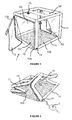
- the figure 1 is a perspective view of a protective device 1 in the deployed position ready to receive goods to protect.
- the device has a generally parallelepipedal shape, that is to say it comprises six faces, a central portion is substantially flat, with the possible exception of the edges. In the vicinity of the edges, two adjacent faces may have between them a right angle or a rounded shape having a radius of curvature more or less pronounced.
- This device comprises a casing 10 made of impervious material comprising walls extending on four faces or five faces of the parallelepiped.
- the face (s) not covered by the envelope form one or two openings for the introduction of the goods to be protected. In the position of use, this or these openings extend in a plane perpendicular to the floor of the building in which the protective device is installed, that is to say generally in a vertical plane.
- said faces 1A, 1B correspond to two opposite faces of the parallelepiped.
- the protective device is intended to adopt a folded configuration in which it occupies the most compact volume possible for its transport and storage, and an expanded configuration in which it defines an interior volume in which goods to be protected can be arranged
- the envelope is made of a foldable material.
- the material of the envelope 10 is chosen according to the tightness to be ensured. It may indeed be, depending on the application, a watertight seal, a dust seal or an airtightness.
- the skilled person is able to choose, from the materials available on the market, a material suitable for the intended application.
- the material must have sufficient mechanical strength to avoid the risk of tearing during contact or friction exerted by a good stored in the device.
- the envelope is made of a transparent or translucent material in order to display the goods stored therein.
- the envelope may be opaque to provide protection against UV radiation.
- the envelope is chosen for a self-extinguishing material, in order to minimize the risk of fire.
- PVC is an example of a self-extinguishing material that is waterproof, air and dust proof.
- One of the walls of the envelope namely the wall 10A intended to be placed on the ground and to receive the goods to be protected, may advantageously be formed of a stronger material than the other walls of the envelope.
- said floor wall may be made of textile coated with PVC or have a greater thickness than the other walls of the envelope.
- the different walls of the envelope are integral with each other.
- the walls formed of the same material can be made in one piece, while two walls made of different materials can be assembled by any suitable means, such as welding, gluing, etc.
- the device 1 further comprises a plurality of inflatable strips 11 which are secured to the walls of the casing 10 removably.
- the inflatable strips 11 extend in three different directions, preferably substantially orthogonal.
- the device having a parallelepiped shape, at least a portion of the strips are advantageously arranged along edges of the parallelepiped.
- the threshold of the openings 1A, 1B is preferably free of inflatable band.
- the inflatable bands are in fluid connection with each other, so that when air is injected through a nozzle located in one of the bands, all the bands inflates.
- the inflatable strips are arranged outside the envelope, so as not to encumber the internal volume, which optimizes the storage volume and facilitate the separation of the strips vis-à-vis the envelope .
- the figure 2 is a view of the device during the inflation of the strips 11 by means of a pump 2.
- the pump 2 is able to both inject the air strips and remove.
- the envelope expands until the strips and the walls of the envelope are stretched in three directions.
- the device stands up autonomously, that is to say that no human intervention is necessary outside of the implementation of the pump for inflation. In particular, no intervention is necessary to maintain the envelope or bands in their final position during inflation.
- the strips 11 are sized to support the weight of the envelope when inflated; thus, once in the deployed position in the air, the device is self-supporting, that is to say that it does not require any external support to remain in the deployed position.
- the device comprises two inflation / deflation tips strips 11, arranged on different faces of the device for promote access to at least one of said tips according to the positioning of the device in the building.
- the inflatable bands 11 are arranged outside the envelope. Thus, they do not interfere with the goods housed in the protective device.
- the inflation or deflation tip (s) are thus accessible from the outside of the device, which facilitates its deployment and its folding.
- the inflatable strips are in a foldable material.
- the inflatable bands 11 are distinct from the envelope 10, that is to say that they are made independently of the envelope and then secured to the envelope by a reversible connection means 110.
- the securing means may be for example a snap, self-gripping strips (Velcro® type), etc.
- the fact of dissociating the envelope of the inflatable strips makes it possible to choose, for each of these components, the most suitable material for the function that it must fulfill.
- an extensible material is chosen: this makes it possible, when the envelope is emptied, that the envelope comes to marry without constraint the goods contained therein.
- a less extensible material is preferably chosen in order to favor the inflation in the longitudinal direction of each band.
- the device further comprises at least one door 12 for closing the open face or faces of the envelope.
- Said door is also made of a flexible and waterproof material and can be made, for example, in the same material as the envelope.
- the device comprises a sealed assembly system of the door on the envelope.
- the assembly system is chosen according to the type of sealing required.
- Such a system typically comprises a first fastening strip 13a disposed on the periphery of the opening 1A of the envelope and a second fastening strip 13b disposed on the periphery of the door 12, said fastener strips having shapes complementary to each other.
- the mutual engagement of said complementary shapes can be carried out manually by an operator but, advantageously, the assembly system is a slide fastener system, which comprises a slider whose displacement ensures the meshing of the complementary shapes arranged on each said fastening strips.
- the fastener strips may be provided with teeth which mesh during the movement of the cursor. Ties are designed so that the cursor can be manipulated both from the outside (for the closing or opening of the door or doors) and from the inside (for the assembly of 2 envelopes as described below).
- the envelope is open on two opposite faces 1A, 1B.
- the envelope is closed by two doors which close the interior volume, which provides a unitary protection volume (cf. figure 1 ).
- the door intended to close the face 1A is provided with fastening strips having the second profile and the door for closing the face 1 B is provided with fastening strips having the first profile.
- the internal volume of the device when the strips 11 are inflated is less than or equal to 10 m 3 .
- the envelope 10 is assembled with another similar envelope 10 ', by means of the fastening strips of the assembly system (by assembling fastening strips having complementary profiles), and the open face of each envelope is closed by a door.
- This doubles the internal volume of protection, which protects large elongated goods.
- the assembly of the different devices can be realized directly, without adding intermediate parts to connect them.
- fastening strip 13a integral with the envelope against the constraints on the loading and unloading of goods, including the passage of operators or transport trolleys.
- the device comprises a protection system of the fastening strip which comprises firstly a series of blocks 16 integral with the envelope and one or more sections 17 coupled to the blocks 16 removably.
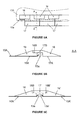
- the Figure 5A is a partial top view of the threshold of the device, having a portion of the floor wall 10A and the fastening strip 13a attached thereto.
- the blocks 16 are arranged at a distance from each other so as not to hinder the folding of the floor wall and are set back towards the inside of the wall with respect to the fastening strip 13a.
- Blocks 16 support profiles 17 which are arranged continuously along the threshold.
- the blocks 16 have a substantially triangular profile comprising a base 16A resting on the ground and a bearing zone 16B for the profiles 17.
- the profiles 17 have a portion of triangular section comprising a base 17A resting on the ground and a portion 17B in protrusion relative to the triangular portion, of substantially parallelepipedal shape extending to the blocks 16 so as to rest on the zone d 16B support.
- the parallelepipedal portion 17B is long enough to provide a free space for the fastening strip 13a between the blocks 16 and the triangular section portion of the profiles 17.
- the blocks 16 and the profiles 17 are made of a sufficiently rigid material to withstand the weight of an operator or a truck during the loading or unloading of goods. In addition, their triangular profile forms a slope that minimizes the obstacle formed by these blocks and profiles.
- the blocks and the profiles are for example made of a rigid plastic material.
- the blocks 16 are for example welded to the inner face of the floor wall 10A.
- the profiles 17 are removed in order to close the door.
- the Figure 5C illustrates a variant of the Figure 5B corresponding to the case where two envelopes 10, 10 'are assembled to form a larger protective volume.
- each envelope is provided with the blocks 16, 16' described above.
- the envelopes 10, 10 ' are assembled through the fastening strips 13a, 13a' which have complementary shapes.
- the profiles 17 ' are parallelepipedal profiles which rest on the bearing areas of the blocks 16, 16' located on either side of the assembly system 13a, 13a '.
- the profiles 17 'remain in place in the protective volume during the entire use of the protective device, and are removed when the device is disassembled and the envelopes are folded.
- the flaps 18a, 18a ' may have different lengths on each side so that they overlap when assembling 2 modules.
- the Figure 6B is a partial sectional view of such an assembly.
- the device 1 in the context of an application to the protection of property against a flood, the device 1 must be able to be secured to a fixed support to limit its movements in case of flotation.
- the casing 10 comprises, on at least two of its faces, a respective anchoring member A2 for securing the device to a support.
- this anchoring member A2 has for example a hook or a handle for attaching a link 3 resistant to traction, such as a rope or a cable for example.
- a securing means 2 is provided in the form of a flexible strip 20 provided at one end with a fastening member 21 on which the link 3 can be hung and at the end opposite, of a ring 22 (visible on the Figure 7B ) is arranged in a removable manner in a housing 23.
- Said housing is for example in the form of a hem formed at the end of the strip 20.
- This lashing means 2 is designed to cooperate with all types of openings used in a building (doors, windows, swinging or sliding French windows). As illustrated on the Figure 7B in the case of a window, it is sufficient to open the window 4, to slide the end of the strip 20 comprising the housing 23 in the opening 42 between the frame 41 and the flap (the ring 22 does not). being then not in the housing 23) (arrow I), then insert the rod 22 in the housing 23 (arrow II).
- the rod 22 having a larger diameter than the opening 42, it forms a means of retaining the band 21 vis-à-vis the window, that it is open or closed. This system thus provides great securing security, even in the case of accidental opening of the window. In the case of a sliding French window, it is however necessary that it is closed after the establishment of the rod in its housing.
- the length of the link 3 is adjusted according to the distance between the protective device and the window or the door to which it is stowed.
- the device 1 further comprises a pressure relief valve arranged on one of the walls of the casing, in the upper part of the device.
- the device may comprise a valve 15 arranged in the wall opposite the floor wall and / or a valve 15A arranged in the upper part of a vertical wall, which facilitates access to said valve to evacuate the air from the volume inside.
- the pressure exerted by the water on the walls of the envelope increases the pressure of the air contained in the volume.
- the flapper allows to evacuate all or part of the air contained in the interior volume when the pressure exceeds a certain value.
- the pressure relief valve can be connected to a pump which makes it possible to evacuate the interior volume of the envelope once the goods to be protected have been installed therein.
- This provision is particularly useful when a risk of flooding is incurred. Indeed, if there is air in the interior volume, the goods contained therein may be destabilized by the rise of water and move relative to each other, inducing a risk of damage to the envelope and / or other property.
- To evacuate in the interior volume makes it possible to press the walls of the envelope against the external surfaces of the goods contained therein and thus to stabilize the whole.
- the inflatable strips are previously detached so as to minimize the mechanical stresses exerted on the envelope during its plating on the interior contents.
- the same pump as used to inflate the strips 11 is used.
- the tip of the pump intended to be connected to the pressure relief valve comprises a pressure limiter which makes it possible to obtain the level of pressure. desired depression inside the envelope.
- the material of the enclosure and the door of the protection device and the system of assembly of the door are designed to be waterproof.
- the protection device can be delivered in the form of a kit including a pump with the above-mentioned pressure limiter and two securing means 2 as described above.
- the user has at his disposal all the elements allowing him to set up the protection device quickly in case of risk of flooding.
- the device is watertight - and more generally fluid - it can also be used to store leaking containers, in order to confine any leaks inside the protective volume and prevent their flow to the container. outside.
- Another use of the device concerns the protection of material goods against dust, for example on a construction site.
- the material of the enclosure and the door of the protection device and the assembly system of the door are designed to be airtight and / or dustproof.
- Such a device allows for example to protect the furniture of a room being renovated without leaving the room while providing more effective protection than the tarpaulins conventionally used.
- Another use of the device concerns the protection of material goods against moisture and / or mold.
- the material of the envelope and the door the protection device and the door assembly system are designed to be airtight.
- Such a device allows for example to store objects for a long time without altering them.
- One possible application is the protection of works of art in a museum reserve or the preservation of archives. For this application it will eventually be possible to empty the interior volume in order to limit the contact of the contents with the ambient air.
- the device further comprises an internal or external air conditioning system for regulating the hygrometry and / or temperature in the interior volume, in order to maintain the optimal conditions of conservation of the goods to be protected.
Landscapes
- Engineering & Computer Science (AREA)
- Architecture (AREA)
- Physics & Mathematics (AREA)
- Fluid Mechanics (AREA)
- Civil Engineering (AREA)
- Structural Engineering (AREA)
- Tents Or Canopies (AREA)
Applications Claiming Priority (1)
| Application Number | Priority Date | Filing Date | Title |
|---|---|---|---|
| FR1452697A FR3019160A1 (fr) | 2014-03-28 | 2014-03-28 | Dispositif de protection d'un bien materiel et utilisation d'un tel dispositif pour proteger un bien materiel |
Publications (1)
| Publication Number | Publication Date |
|---|---|
| EP2933400A1 true EP2933400A1 (de) | 2015-10-21 |
Family
ID=50877474
Family Applications (1)
| Application Number | Title | Priority Date | Filing Date |
|---|---|---|---|
| EP15161409.6A Withdrawn EP2933400A1 (de) | 2014-03-28 | 2015-03-27 | Schutzvorrichtung eines materiellen gutes, und verwendung einer solchen vorrichtung zum schützen eines materiellen gutes |
Country Status (2)
| Country | Link |
|---|---|
| EP (1) | EP2933400A1 (de) |
| FR (1) | FR3019160A1 (de) |
Cited By (4)
| Publication number | Priority date | Publication date | Assignee | Title |
|---|---|---|---|---|
| WO2019202232A1 (fr) * | 2018-04-18 | 2019-10-24 | Emmanuel Fievet | Hangar modulaire gonflable |
| FR3115806A1 (fr) * | 2020-10-30 | 2022-05-06 | Hopitaux Du Leman | sas modulaire déplaçable |
| DE102021109798A1 (de) | 2021-04-19 | 2022-10-20 | X GLOO GmbH & Co. KG | Mobiles Bauwerk |
| CN118479180A (zh) * | 2024-05-24 | 2024-08-13 | 广州工程技术职业学院 | 搬运设备及物料搬运方法 |
Citations (7)
| Publication number | Priority date | Publication date | Assignee | Title |
|---|---|---|---|---|
| GB2104569A (en) | 1981-08-27 | 1983-03-09 | Secr Defence | Inflatable temporary cabin |
| US4736762A (en) | 1985-12-16 | 1988-04-12 | Wayman Joseph R | Anti-contamination means |
| US4876829A (en) | 1988-01-19 | 1989-10-31 | Pneumo-Beam International Ltd. | Inflatable tent structure |
| GB2323395A (en) * | 1997-03-17 | 1998-09-23 | Plysu Protection Systems Limit | Inflatable structure |
| US20020083653A1 (en) | 1999-09-10 | 2002-07-04 | Hilbert Clint J. | Rapidly deployable protective enclosure |
| US20030098054A1 (en) | 2001-11-27 | 2003-05-29 | Yang Hong Yuan | Waterproof vehicle parking shade device |
| FR2963943A1 (fr) | 2010-08-22 | 2012-02-24 | Sperian Prot Clothing | Sas de confinement |
-
2014
- 2014-03-28 FR FR1452697A patent/FR3019160A1/fr active Pending
-
2015
- 2015-03-27 EP EP15161409.6A patent/EP2933400A1/de not_active Withdrawn
Patent Citations (7)
| Publication number | Priority date | Publication date | Assignee | Title |
|---|---|---|---|---|
| GB2104569A (en) | 1981-08-27 | 1983-03-09 | Secr Defence | Inflatable temporary cabin |
| US4736762A (en) | 1985-12-16 | 1988-04-12 | Wayman Joseph R | Anti-contamination means |
| US4876829A (en) | 1988-01-19 | 1989-10-31 | Pneumo-Beam International Ltd. | Inflatable tent structure |
| GB2323395A (en) * | 1997-03-17 | 1998-09-23 | Plysu Protection Systems Limit | Inflatable structure |
| US20020083653A1 (en) | 1999-09-10 | 2002-07-04 | Hilbert Clint J. | Rapidly deployable protective enclosure |
| US20030098054A1 (en) | 2001-11-27 | 2003-05-29 | Yang Hong Yuan | Waterproof vehicle parking shade device |
| FR2963943A1 (fr) | 2010-08-22 | 2012-02-24 | Sperian Prot Clothing | Sas de confinement |
Cited By (5)
| Publication number | Priority date | Publication date | Assignee | Title |
|---|---|---|---|---|
| WO2019202232A1 (fr) * | 2018-04-18 | 2019-10-24 | Emmanuel Fievet | Hangar modulaire gonflable |
| FR3080391A1 (fr) * | 2018-04-18 | 2019-10-25 | Emmanuel Fievet | Hangar modulaire gonflable. |
| FR3115806A1 (fr) * | 2020-10-30 | 2022-05-06 | Hopitaux Du Leman | sas modulaire déplaçable |
| DE102021109798A1 (de) | 2021-04-19 | 2022-10-20 | X GLOO GmbH & Co. KG | Mobiles Bauwerk |
| CN118479180A (zh) * | 2024-05-24 | 2024-08-13 | 广州工程技术职业学院 | 搬运设备及物料搬运方法 |
Also Published As
| Publication number | Publication date |
|---|---|
| FR3019160A1 (fr) | 2015-10-02 |
Similar Documents
| Publication | Publication Date | Title |
|---|---|---|
| EP2933400A1 (de) | Schutzvorrichtung eines materiellen gutes, und verwendung einer solchen vorrichtung zum schützen eines materiellen gutes | |
| FR2531475A1 (fr) | Dispositif de protection, notamment d'habitation individuelle, contre les inondations | |
| WO1998006923A1 (fr) | Procede et dispositif de protection des constructions contre les inondations et les coulees de boues | |
| FR2987573A1 (fr) | Valise pour outillage a main et outillage energise | |
| WO2016046507A1 (fr) | Dispositif portable de confinement pour la manipulation de substances biologiques et/ou chimiques et enceinte de confinement amovible pour un tel dispositif | |
| EP0954661B1 (de) | Struktur mit einem flachen aufblasbaren wandelement | |
| FR3037288A1 (fr) | Dispositif gonflable de protection d'un objet, en particulier contre la grele | |
| FR2664237A1 (fr) | Structure gonflable comportant des conteneurs remplis de liquide. | |
| EP3955777A2 (de) | Luftfüllvorrichtung wie etwa eine expansionsvorrichtung mit schnellverschluss | |
| WO2014202558A1 (fr) | Dispositif de protection de batiment, kit de protection et procede de mise en oeuvre | |
| EP1361806A1 (de) | Koffer mit einer volumenreduktionsvorrichtung | |
| BE1020157A3 (fr) | Dispositif amovible de retenue des eaux. | |
| FR2917442A1 (fr) | Tambour modulaire pour l'enroulement ou le deroulement d'un element couvrant. | |
| FR3073542A1 (fr) | Piscine comportant des moyens d’isolation thermique et d’etancheite a l’air de toutes les faces du bassin | |
| CA2646190C (fr) | Panneau anti-inondations | |
| FR2589901A1 (fr) | Enceinte extensible a parois en panneaux assembles. | |
| FR2874207A1 (fr) | Dispositif de protection d'un objet contre l'immersion | |
| FR3112725A1 (fr) | Protection anti-grêle | |
| FR2697860A1 (fr) | Dôme modulaire de couverture de chantier ou autres espaces. | |
| EP4290015A1 (de) | Flutungssperrsystem | |
| FR3005483A1 (fr) | Volet gonflable et espace equipe dudit volet | |
| FR3163964A1 (fr) | Ensemble gonflable pour piscine | |
| FR3128148A1 (fr) | Boîte à gants portative pour intervention hors laboratoire | |
| FR3001947A1 (fr) | Dispositif d'aeration amovible pour panneaux de pont ouvrant | |
| FR2765453A1 (fr) | Aquarium pliant a structure autoporteuse |
Legal Events
| Date | Code | Title | Description |
|---|---|---|---|
| PUAI | Public reference made under article 153(3) epc to a published international application that has entered the european phase |
Free format text: ORIGINAL CODE: 0009012 |
|
| AK | Designated contracting states |
Kind code of ref document: A1 Designated state(s): AL AT BE BG CH CY CZ DE DK EE ES FI FR GB GR HR HU IE IS IT LI LT LU LV MC MK MT NL NO PL PT RO RS SE SI SK SM TR |
|
| AX | Request for extension of the european patent |
Extension state: BA ME |
|
| STAA | Information on the status of an ep patent application or granted ep patent |
Free format text: STATUS: THE APPLICATION IS DEEMED TO BE WITHDRAWN |
|
| 18D | Application deemed to be withdrawn |
Effective date: 20160422 |