EP2933404B1 - Ouverture de porte comprenant un contact de retour d'information - Google Patents
Ouverture de porte comprenant un contact de retour d'information Download PDFInfo
- Publication number
- EP2933404B1 EP2933404B1 EP15159967.7A EP15159967A EP2933404B1 EP 2933404 B1 EP2933404 B1 EP 2933404B1 EP 15159967 A EP15159967 A EP 15159967A EP 2933404 B1 EP2933404 B1 EP 2933404B1
- Authority
- EP
- European Patent Office
- Prior art keywords
- door opener
- section
- spacer
- diameter
- lug
- Prior art date
- Legal status (The legal status is an assumption and is not a legal conclusion. Google has not performed a legal analysis and makes no representation as to the accuracy of the status listed.)
- Not-in-force
Links
- 125000006850 spacer group Chemical group 0.000 claims description 72
- 230000000903 blocking effect Effects 0.000 claims description 7
- 239000002131 composite material Substances 0.000 claims description 2
- 239000002184 metal Substances 0.000 claims description 2
- 238000012544 monitoring process Methods 0.000 description 3
- 238000003780 insertion Methods 0.000 description 2
- 230000037431 insertion Effects 0.000 description 2
- 238000004519 manufacturing process Methods 0.000 description 2
- 230000000295 complement effect Effects 0.000 description 1
- 238000010276 construction Methods 0.000 description 1
- 238000011109 contamination Methods 0.000 description 1
- 238000011156 evaluation Methods 0.000 description 1
- 239000002360 explosive Substances 0.000 description 1
- 238000009434 installation Methods 0.000 description 1
- 238000012806 monitoring device Methods 0.000 description 1
- 230000007935 neutral effect Effects 0.000 description 1
- 230000000284 resting effect Effects 0.000 description 1
Images

Classifications
-
- E—FIXED CONSTRUCTIONS
- E05—LOCKS; KEYS; WINDOW OR DOOR FITTINGS; SAFES
- E05B—LOCKS; ACCESSORIES THEREFOR; HANDCUFFS
- E05B47/00—Operating or controlling locks or other fastening devices by electric or magnetic means
- E05B47/0046—Electric or magnetic means in the striker or on the frame; Operating or controlling the striker plate
- E05B47/0047—Striker rotating about an axis parallel to the wing edge
-
- E—FIXED CONSTRUCTIONS
- E05—LOCKS; KEYS; WINDOW OR DOOR FITTINGS; SAFES
- E05B—LOCKS; ACCESSORIES THEREFOR; HANDCUFFS
- E05B17/00—Accessories in connection with locks
- E05B17/0004—Lock assembling or manufacturing
-
- E—FIXED CONSTRUCTIONS
- E05—LOCKS; KEYS; WINDOW OR DOOR FITTINGS; SAFES
- E05B—LOCKS; ACCESSORIES THEREFOR; HANDCUFFS
- E05B47/00—Operating or controlling locks or other fastening devices by electric or magnetic means
- E05B2047/0048—Circuits, feeding, monitoring
- E05B2047/0067—Monitoring
- E05B2047/0068—Door closed
Definitions
- the invention relates to a door opener for locking or releasing a standing in the closed position wing of a door or a window according to the features of the preamble of claim 1.
- Such a door opener is in the EP 2 514 889 A2 shown.
- the housing of the door opener has a feedback contact with a switching flag.
- the switching lug has a round cross-section and is rotatably mounted in a receptacle of the housing.
- Door openers with feedback contact are already known from practice. That's how it shows DE 603 09 490 T2 a door opener with a arranged in the door opener latch tag for the feedback contact. This switching flag has a round cross-section. The switch lug is inserted after removal of the strike plate in a groove of the door opener.
- Next door openers are known from practice, which have a groove for storage of the feedback flap in their door opener housing, in which a formed as a stamped part switching flag is inserted.
- the switch tag interacts with a feedback contact.
- the feedback contact has a relatively undefined switching point, and that without additional Transport lock the feedback flap may possibly fall out of the groove. It is an object of the present invention to provide a door opener having a structurally simple construction a well-defined switching point. Preferably, it should be provided that the feedback contact has a captive held switching flag. This object is achieved by a door opener with the features of claim 1. It is envisaged that the door opener has a door opener housing with a receptacle for the feedback contact or a spacer or a contact lug of the feedback contact.
- the inclusion of the door opener housing has for insertion of the feedback contact or a spacer and / or a contact lug on a slot which is at least as wide as the thickness of the contact lug in the region of the spacer wherein the diameter of the round cross section of the spacer is greater than the width of the slot.
- This configuration allows easy installation or production of the door opener by the spacer or the contact lug of the feedback contact is simply inserted from the side into the receptacle.
- the opposite the slot wider diameter of the spacer also reduces the risk that the spacer may accidentally fall out of the receptacle of the door opener housing.
- An additional backup or attachment of the spacer is not required.
- the contact lug or the spacer will not be lost or inadvertently deformed.
- the feedback contact has a contact lug which covers a region of the door opener trap, preferably covers a portion of the door opener trap, and which has a spacer which at least partially has a round cross-section which is captively mounted in the receptacle.
- the receptacle surrounds the round cross section at least partially and forms a pivot bearing for the spacer.
- the contact lug is rotatably connected via the spacer with a switching lug.
- the switching flag interacts with a switching contact, which enables electronic monitoring of the feedback flap.
- the spacer of the switching lug is received in a receptacle of the door opener by the spacer at least partially has a round cross-section which is captively mounted in the receptacle and the receptacle surrounds the circular cross-section at least partially to form a pivot bearing for the spacer.
- the spacer is thus pivotally mounted in a pivot bearing.
- the pivot bearing forms a defined pivot axis about which the spacer can rotate.
- the door opener is installed in a stationary frame of a door or a window, or is arranged resting on the frame.
- the door opener may also be mounted in or on a wing of a door or a window.
- the door opener latch of the door opener interacts with a latch, preferably a spring-loaded latch with inlet bevel to the wing of the door or the Keep window in its closed position.
- the latch located in the closed position of the wing in engagement with the door opener latch actuates the feedback contact.
- the latch presses down the contact lug so that it is pivoted in the direction of the door opener latch.
- the contact lug is rotatably connected to the spacer and therefore rotates the spacer in the pivot bearing.
- This rotational movement is transmitted to the switching flag, which actuates an electrical switching contact.
- the switching contact can be connected via an electrical connection line to a central, such as an access control device or an alarm system. In the center then an evaluation of the feedback contact of the door opener. If the latch opens when it opens or with the sash open out of engagement with the door opener trap, so the switching flag and thus the contact lug is returned to its neutral position via a spring.
- the receptacle of the door opener housing has a width of the slot tapered projection to prevent accidental removal of the spacer from the receptacle.
- the projection prevents the spacer from falling out of the receptacle along its longitudinal axis.
- the round cross section of the recording of the door opener housing completely surrounds the cross section of the spacer in a range which is greater than 190 °, preferably greater than 230 °.
- the spacer has a first portion with a first round cross section having a larger diameter, and a second portion having a second round cross section having a smaller diameter comprises. It is provided that the first section with a larger diameter is arranged in the region of the switching lug, and the second section with a smaller diameter is arranged in the region of the contact lug.
- the inclusion of the door opener housing is correspondingly formed to be complementary to the spacer, so that the receptacle of the door opener housing for supporting the spacer has a first receiving portion and a second receiving portion.
- the first receiving portion has a larger cross section than the second receiving portion.
- the spacer is mounted in the door opener housing by providing that the first receiving portion has a diameter that corresponds to the diameter of the first portion of the spacer, preferably a same or slightly larger diameter, and the second receiving portion has a diameter of the second portion of the Spacer has corresponding diameter, preferably with the same or larger diameter than the second portion.
- the spacer is stored in the first receiving portion and in the second receiving portion predominantly without play.
- the spacer can be mounted in the receptacle in such a way that the diameter of the first receiving section is matched to the diameter of the first section of the spacer for precisely fitting the spacer.
- the first receiving portion thus forms a possible backlash-free pivot bearing.
- the second Receiving portion has a diameter which is larger than the diameter of the second portion and smaller than the diameter of the first portion, so that the second portion is guided with play in the second receiving portion.
- the first portion of the receptacle forms a pivot bearing for the spacer and the second portion of the receptacle has a larger game. It merely forms a guide for the spacer. This results in a statically determined storage of the spacer in the pivot bearing or in the first section of the recording.
- the switching lug and the contact lug are arranged cantilevered on one side of the spacer.
- the switching lug and the contact lug are integrally connected to the spacer, preferably that the switching lug and the contact lug and the spacer are integrally formed.
- the switching lug and the contact lug form together with the spacer a one-piece reminder a person, which consists of a metal or a plastic or a composite material.
- An application of the door opener can be done as a locking device in doors or windows. Even with security-related accesses the door opener according to the invention can be used.
- the door opener can be configured as an electrically operated, in particular electrically remote-controlled, door opener.
- the door opener may be formed in another embodiment as a pneumatically actuated, in particular pneumatically remotely operated door opener.
- a pneumatically operated door opener it is particularly suitable for use in a potentially explosive atmosphere.
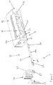
- Fig. 1 shows a door opener 1 with a door opener housing 11.
- the door opener housing 11 is formed substantially cuboid and has a removable lid.
- the removable lid 12 completes a space of the door opener housing 11, in which components of the door opener 1, such as a blocking device 15 and a movably mounted door latch 14 are received.
- the door opener 1 can be installed in a fixed frame of a door or a grand piano. He can be installed in particular in a lock counter box or connected to a strike plate.
- the door opener housing 11 has two attachment openings 13a and 13b on its front side. These are in the representation of Fig. 1 left and right of the door opener housing 11 pivotally mounted in the door opener trap 14 arranged.
- the door opener 1 has a feedback contact 3.
- the feedback contact 3 detects an engagement of a latch in the door latch 14 and reports this electrically.
- An electrical terminal block 34 of the feedback contact 3 is protected by a cover 33 and mounted laterally on the door opener housing 11.
- the feedback contact 3 has an electrical switch, such as a micro-switch, and a spacer 38.
- the spacer has a feedback contact lug 35, with a contact lug 36 and with a switching lug 37, which are rotatably connected to each other via the spacer 38.
- the door opener housing 11 has a receptacle 2, which supports the feedback contact lug 35.
- the receptacle 2 is formed in a wall of the door opener housing 11, preferably at the bottom of the door opener housing 11.
- Fig. 2 the door opener 1 is shown in an exploded view.
- the receptacle 2 has a cross section with two different diameters. It has a first section 21 with a larger diameter and a second section 22 with a smaller diameter.
- the receptacle 2 is open in the direction of the end face of the door opener housing 11. It has a slot 24 which extends along the receptacle 22 and extends both along the first portion 21 as well as along the second portion 22 extends. This slot 24 serves to ensure that the feedback contact lug 35 can be pushed laterally into the door opener housing 11 during assembly.
- the width of the slot 24 is dimensioned such that the width of the contact lug 36 in the region near the spacer 38 is smaller than the width of the slot 24.
- the receptacle 2 in the wall region of the slot 24 has a projection 23 which reduces the cross-section of the slot 24, so that the remindmeldeAuthfahne 35 on its way out of the receptacle 2 out of the Projection 23 is caught.
- the feedback contact lug 35 has a spacer 38 which has a round cross-section.
- the spacer 38 has a first portion 381 with a larger diameter and a second portion 382 with a smaller diameter.
- a switching lug 37 is non-rotatably connected to the spacer 38.
- a contact lug 36 is non-rotatably connected to the second section 382 of the spacer 38.
- the switching lug 37 and the contact lug 36 are arranged on one side cantilevered on the spacer 38. A movement of the contact lug 36 is transmitted via the spacer 38 to the switch lug 37 and vice versa.
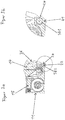
- Fig. 3a a section through the door opener in the region of the second portion 382 is shown.
- the second receiving portion 22, in which the second portion 382 of the spacer 38 is pivotally mounted, is located as in the presentation of the Fig. 3a shown below the door opener 14 pivotally mounted in the door opener housing 11 in the region of the bottom of the door opener housing.
- the pivotally mounted door opener latch 14 cooperates with a blocking device 15, which releases or blocks movement of the door opener latch 14.
- the contact lug 36 is arranged in the region of the door opener latch 14 such that it covers a portion of the door opener latch 14.
- the switch lug 36 is disposed in the center of the door opener latch 14, so that a latch corresponding to the door latch latch 14 securely operates the contact lug 36.
- a section through the door opener housing 11 in the region of the first portion 381 is shown.
- the first section 381 is held in a form-fitting manner in the first receiving section 21.
- the first section 21 thus forms a largely backlash-free pivot bearing for the spacer 38.
- the switching lug 37 arranged in the region of the first section 381 cooperates with a switch 31 of the feedback contact 3, as in FIG Fig. 2 is shown.
- the switch 31 has a spring-loaded switching lug 32, which interacts directly with the switching lug 37.
- Via the terminal block 34 the contacts of the switch 31 can be connected to a higher-level control center or to an alarm system.
- a cover 33 covers the switch 31 and partially the terminal block 34 in order to protect it against contamination or mechanical damage.
- the switch 31 of the feedback contact is designed as a changeover switch. It can be connected either as normally open (NO) or normally closed (NC) switch.
- the electrical connections of the Switch 31 can be guided via the terminal block 34 by means of cable connection away from the door opener 1 and to a distributor or be guided to a higher-level control or monitoring device.
Landscapes
- Engineering & Computer Science (AREA)
- Manufacturing & Machinery (AREA)
- Closures For Containers (AREA)
- Rotary Switch, Piano Key Switch, And Lever Switch (AREA)
Claims (10)
- Gâche pour le blocage ou la libération d'un battant de porte ou de fenêtre, se trouvant dans une position fermée, avec un boîtier de gâche (11), dans lequel sont logés un pêne mobile (14) et un dispositif de blocage (15) et le dispositif de blocage comprend un élément de blocage qui, dans la position de blocage du dispositif de blocage, bloque le pêne (14) et, dans la position de libération du dispositif de blocage, libère le pêne (14), et avec un contact de réponse disposé au niveau du pêne, qui comprend un drapeau de contact (36) recouvrant une zone partielle du pêne et un drapeau de commutation (37) interagissant avec un commutateur (31) et le drapeau de contact (36) est relié de manière solidaire en rotation avec le drapeau de commutation (37) par une entretoise (38) et l'entretoise est maintenue dans un logement (2) du boîtier de gâche (11), l'entretoise (38) présentant au moins partiellement une section ronde, qui est logée dans le logement (2) de manière imperdable et le logement (2) entoure au moins partiellement la section ronde afin de former un palier de pivotement pour l'entretoise (38),
le logement (2) du boîtier de gâche (11) comprenant, pour l'insertion du contact de réponse, une fente (24) qui est au moins aussi large que l'épaisseur du drapeau de contact (36) au niveau de l'entretoise (38) et de façon à ce que le diamètre de la section ronde de l'entretoise (38) soit supérieure à la largeur de la fente (24),
caractérisée en ce que
l'entretoise (38) comprend une première portion (381) avec une première section ronde qui présente un diamètre plus grand et une deuxième portion (382) avec une deuxième section ronde qui présente un diamètre plus petit. - Gâche selon la revendication 1, caractérisée en ce que le logement du boîtier de gâche (11) comprend une saillie (23) diminuant la largeur de la fente (24) afin d'empêcher un retrait par inadvertance de l'entretoise (38) hors du logement (2).
- Gâche selon la revendication 1 ou 2, caractérisée en ce que le logement (2) du boîtier de gâche (11) présente une section ronde qui entoure complètement la section de l'entretoise (38) dans une zone qui est supérieure à 190°, de préférence supérieure à 230°.
- Gâche selon l'une des revendications 1 à 3, caractérisée en ce que la première portion (381) avec un diamètre plus grand est disposée au niveau du drapeau de commutation (37) et la deuxième portion (382) avec un diamètre plus petit est disposée au niveau du drapeau de contact (36).
- Gâche selon la revendication 4, caractérisée en ce que le logement (2) du boîtier de gâche (11) comprend, pour le logement de l'entretoise (38), une première portion de logement (21) et une deuxième portion de logement (22), la première portion de logement (21) présentant une section supérieure à la deuxième portion de logement (22).
- Gâche selon al revendication 5, caractérisée en ce que la première portion de logement (21) présente un diamètre qui correspond au diamètre de la première portion (381) de l'entretoise (38), de préférence un diamètre égal ou légèrement supérieur et la deuxième portion de logement (22) présente un diamètre correspondant au diamètre de la deuxième portion (382) de l'entretoise (38), de préférence avec un diamètre égal ou supérieur à la deuxième portion (382).
- Gâche selon la revendication 6, caractérisée en ce que le diamètre de la première portion de logement (21) est adaptée, pour le logement précis de l'entretoise (38), au diamètre de la première portion (381) de l'entretoise (38), de façon à ce que la première portion de logement (21) constitue un palier de pivotement et à ce que la deuxième portion de logement (22) présente un diamètre qui est supérieure au diamètre de la deuxième portion (382) et inférieur au diamètre de la première portion (381), de façon à ce que la deuxième portion (382) soit guidée avec un jeu dans la deuxième portion de logement (22).
- Gâche selon l'une des revendications précédentes, caractérisée en ce que le drapeau de commutation (37) et le drapeau de contact (36) sont disposés sur l'entretoise (38) de façon à dépasser d'un seul côté.
- Gâche selon l'une des revendications précédentes, caractérisée en ce que le drapeau de commutation (37) et le drapeau de contact (36) sont reliés d'une seule pièce avec l'entretoise (38), de préférence en ce que le drapeau de commutation (37) et le drapeau de contact (36) et l'entretoise (38) sont formés d'une seule pièce.
- Gâche selon l'une des revendications précédentes, caractérisée en ce que le drapeau de commutation (37) et le drapeau de contact (36) constituent ensemble un drapeau de contact de réponse (35) d'une seule pièce qui est constitué de métal ou de matière plastique ou d'un matériau composite.
Priority Applications (1)
| Application Number | Priority Date | Filing Date | Title |
|---|---|---|---|
| PL15159967T PL2933404T3 (pl) | 2014-03-25 | 2015-03-19 | Przycisk otwierania drzwi z kontaktem zwrotnym |
Applications Claiming Priority (1)
| Application Number | Priority Date | Filing Date | Title |
|---|---|---|---|
| DE102014104094.5A DE102014104094B4 (de) | 2014-03-25 | 2014-03-25 | Türöffner mit Rückmeldekontakt |
Publications (2)
| Publication Number | Publication Date |
|---|---|
| EP2933404A1 EP2933404A1 (fr) | 2015-10-21 |
| EP2933404B1 true EP2933404B1 (fr) | 2017-07-12 |
Family
ID=52686252
Family Applications (1)
| Application Number | Title | Priority Date | Filing Date |
|---|---|---|---|
| EP15159967.7A Not-in-force EP2933404B1 (fr) | 2014-03-25 | 2015-03-19 | Ouverture de porte comprenant un contact de retour d'information |
Country Status (4)
| Country | Link |
|---|---|
| EP (1) | EP2933404B1 (fr) |
| DE (1) | DE102014104094B4 (fr) |
| ES (1) | ES2643085T3 (fr) |
| PL (1) | PL2933404T3 (fr) |
Families Citing this family (4)
| Publication number | Priority date | Publication date | Assignee | Title |
|---|---|---|---|---|
| DE202017102972U1 (de) | 2017-05-17 | 2017-07-11 | Assa Abloy Sicherheitstechnik Gmbh | Türöffner mit Rückmeldekontakt |
| EP3640418A1 (fr) * | 2018-10-16 | 2020-04-22 | Openers & Closers, S.L. | Dispositif de surveillance applicable aux gâches électriques symétriques |
| ES2959978T3 (es) | 2021-07-27 | 2024-02-29 | Openers & Closers Sl | Cerradero eléctrico con sistema de monitorización |
| EP4257783B1 (fr) * | 2022-04-07 | 2024-08-21 | Openers & Closers, S.L. | Dispositif d'ouverture de porte doté d'un système de surveillance |
Family Cites Families (5)
| Publication number | Priority date | Publication date | Assignee | Title |
|---|---|---|---|---|
| US5735559A (en) * | 1996-08-09 | 1998-04-07 | Harrow Products, Inc. | Electric strike |
| DE10116299C1 (de) * | 2001-03-31 | 2002-10-31 | Ist Systems Gmbh | Elektrischer Türöffener |
| MXPA05004341A (es) | 2002-09-27 | 2005-11-23 | Rutherford Controls Int L Corp | Ensamble de hembra de cerradura electrica. |
| US20100116006A1 (en) * | 2008-11-07 | 2010-05-13 | Chien-Ying Huang | Strike lock with functions of fail security and fail safety |
| DE102011018816B4 (de) * | 2011-04-22 | 2013-04-18 | Assa Abloy Sicherheitstechnik Gmbh | Türöffner |
-
2014
- 2014-03-25 DE DE102014104094.5A patent/DE102014104094B4/de not_active Expired - Fee Related
-
2015
- 2015-03-19 ES ES15159967.7T patent/ES2643085T3/es active Active
- 2015-03-19 PL PL15159967T patent/PL2933404T3/pl unknown
- 2015-03-19 EP EP15159967.7A patent/EP2933404B1/fr not_active Not-in-force
Non-Patent Citations (1)
| Title |
|---|
| None * |
Also Published As
| Publication number | Publication date |
|---|---|
| DE102014104094B4 (de) | 2018-09-13 |
| PL2933404T3 (pl) | 2017-12-29 |
| ES2643085T3 (es) | 2017-11-21 |
| EP2933404A1 (fr) | 2015-10-21 |
| DE102014104094A1 (de) | 2015-10-01 |
Similar Documents
| Publication | Publication Date | Title |
|---|---|---|
| EP1447500B1 (fr) | Dispositif de blocage de sécurité | |
| EP2933404B1 (fr) | Ouverture de porte comprenant un contact de retour d'information | |
| WO2008128672A2 (fr) | Dispositif de verrouillage pour un appareil de coupure d'installation | |
| EP3575520A1 (fr) | Cadenas à arceau | |
| WO2013056759A1 (fr) | Ensemble coupe-circuit multipolaire pour systèmes de barres omnibus | |
| DE102016124557A1 (de) | Anschlagkörper für Betätigungshandhabe, Betätigungshandhabe und Tür | |
| EP3199728B1 (fr) | Ouvre-porte résistant aux chocs | |
| DE4324964C2 (de) | Vorrichtung zur Verriegelung von Schranktüren | |
| DE1160067B (de) | Geschlossenes Schaltgeraet mit Verriegelungseinrichtung | |
| EP3179021B1 (fr) | Système de poignée de porte de véhicule | |
| DE102012108991B4 (de) | Schaltkontakt | |
| DE102019216463A1 (de) | Türwächter | |
| DE2458652C3 (de) | Elektrische Alarmvorrichtung für eine schließzylinderbetätigte Verriegelungsvorrichtung | |
| DE4207128C2 (de) | Kontaktvorrichtung zur elektrischen Überwachung von Eingangstüren | |
| EP3396086A1 (fr) | Ouvre-porte à levier de blocage entre le pêne demi-tour et le levier de serrure | |
| DE102013110442A1 (de) | Türbeschlag zum Betätigen einer Schlossnuss eines Türschlosses | |
| DE102006046839B4 (de) | Branddruckknopfmelder | |
| EP0029489B1 (fr) | Commutateur à touche | |
| DE202017102972U1 (de) | Türöffner mit Rückmeldekontakt | |
| EP1249565A1 (fr) | Serrure | |
| EP1790805B1 (fr) | Mécanisme d'actionnement à levier pour une crémone | |
| EP3594435B1 (fr) | Émetteur d'alarme pour un système de verrouillage de porte | |
| DE7438635U (de) | Vorrichtung zur elektrischen Überwachung der Verriegelung eines Schlosses | |
| DE202006008969U1 (de) | Kantriegel mit Wippe | |
| DE19943214C2 (de) | Stangenverriegelung für Flügel von Fenstern oder Türen |
Legal Events
| Date | Code | Title | Description |
|---|---|---|---|
| PUAI | Public reference made under article 153(3) epc to a published international application that has entered the european phase |
Free format text: ORIGINAL CODE: 0009012 |
|
| AK | Designated contracting states |
Kind code of ref document: A1 Designated state(s): AL AT BE BG CH CY CZ DE DK EE ES FI FR GB GR HR HU IE IS IT LI LT LU LV MC MK MT NL NO PL PT RO RS SE SI SK SM TR |
|
| AX | Request for extension of the european patent |
Extension state: BA ME |
|
| 17P | Request for examination filed |
Effective date: 20160414 |
|
| RBV | Designated contracting states (corrected) |
Designated state(s): AL AT BE BG CH CY CZ DE DK EE ES FI FR GB GR HR HU IE IS IT LI LT LU LV MC MK MT NL NO PL PT RO RS SE SI SK SM TR |
|
| GRAP | Despatch of communication of intention to grant a patent |
Free format text: ORIGINAL CODE: EPIDOSNIGR1 |
|
| RIC1 | Information provided on ipc code assigned before grant |
Ipc: E05B 17/00 20060101ALI20170124BHEP Ipc: E05B 47/00 20060101AFI20170124BHEP |
|
| INTG | Intention to grant announced |
Effective date: 20170216 |
|
| GRAS | Grant fee paid |
Free format text: ORIGINAL CODE: EPIDOSNIGR3 |
|
| GRAA | (expected) grant |
Free format text: ORIGINAL CODE: 0009210 |
|
| AK | Designated contracting states |
Kind code of ref document: B1 Designated state(s): AL AT BE BG CH CY CZ DE DK EE ES FI FR GB GR HR HU IE IS IT LI LT LU LV MC MK MT NL NO PL PT RO RS SE SI SK SM TR |
|
| REG | Reference to a national code |
Ref country code: GB Ref legal event code: FG4D Free format text: NOT ENGLISH |
|
| REG | Reference to a national code |
Ref country code: CH Ref legal event code: EP |
|
| REG | Reference to a national code |
Ref country code: AT Ref legal event code: REF Ref document number: 908498 Country of ref document: AT Kind code of ref document: T Effective date: 20170715 |
|
| REG | Reference to a national code |
Ref country code: IE Ref legal event code: FG4D Free format text: LANGUAGE OF EP DOCUMENT: GERMAN |
|
| REG | Reference to a national code |
Ref country code: DE Ref legal event code: R096 Ref document number: 502015001402 Country of ref document: DE |
|
| REG | Reference to a national code |
Ref country code: NL Ref legal event code: FP |
|
| REG | Reference to a national code |
Ref country code: SE Ref legal event code: TRGR |
|
| REG | Reference to a national code |
Ref country code: ES Ref legal event code: FG2A Ref document number: 2643085 Country of ref document: ES Kind code of ref document: T3 Effective date: 20171121 |
|
| REG | Reference to a national code |
Ref country code: LT Ref legal event code: MG4D |
|
| PG25 | Lapsed in a contracting state [announced via postgrant information from national office to epo] |
Ref country code: FI Free format text: LAPSE BECAUSE OF FAILURE TO SUBMIT A TRANSLATION OF THE DESCRIPTION OR TO PAY THE FEE WITHIN THE PRESCRIBED TIME-LIMIT Effective date: 20170712 Ref country code: LT Free format text: LAPSE BECAUSE OF FAILURE TO SUBMIT A TRANSLATION OF THE DESCRIPTION OR TO PAY THE FEE WITHIN THE PRESCRIBED TIME-LIMIT Effective date: 20170712 Ref country code: HR Free format text: LAPSE BECAUSE OF FAILURE TO SUBMIT A TRANSLATION OF THE DESCRIPTION OR TO PAY THE FEE WITHIN THE PRESCRIBED TIME-LIMIT Effective date: 20170712 Ref country code: NO Free format text: LAPSE BECAUSE OF FAILURE TO SUBMIT A TRANSLATION OF THE DESCRIPTION OR TO PAY THE FEE WITHIN THE PRESCRIBED TIME-LIMIT Effective date: 20171012 |
|
| REG | Reference to a national code |
Ref country code: FR Ref legal event code: PLFP Year of fee payment: 4 |
|
| PG25 | Lapsed in a contracting state [announced via postgrant information from national office to epo] |
Ref country code: RS Free format text: LAPSE BECAUSE OF FAILURE TO SUBMIT A TRANSLATION OF THE DESCRIPTION OR TO PAY THE FEE WITHIN THE PRESCRIBED TIME-LIMIT Effective date: 20170712 Ref country code: LV Free format text: LAPSE BECAUSE OF FAILURE TO SUBMIT A TRANSLATION OF THE DESCRIPTION OR TO PAY THE FEE WITHIN THE PRESCRIBED TIME-LIMIT Effective date: 20170712 Ref country code: BG Free format text: LAPSE BECAUSE OF FAILURE TO SUBMIT A TRANSLATION OF THE DESCRIPTION OR TO PAY THE FEE WITHIN THE PRESCRIBED TIME-LIMIT Effective date: 20171012 Ref country code: IS Free format text: LAPSE BECAUSE OF FAILURE TO SUBMIT A TRANSLATION OF THE DESCRIPTION OR TO PAY THE FEE WITHIN THE PRESCRIBED TIME-LIMIT Effective date: 20171112 Ref country code: GR Free format text: LAPSE BECAUSE OF FAILURE TO SUBMIT A TRANSLATION OF THE DESCRIPTION OR TO PAY THE FEE WITHIN THE PRESCRIBED TIME-LIMIT Effective date: 20171013 |
|
| REG | Reference to a national code |
Ref country code: DE Ref legal event code: R097 Ref document number: 502015001402 Country of ref document: DE |
|
| PG25 | Lapsed in a contracting state [announced via postgrant information from national office to epo] |
Ref country code: CZ Free format text: LAPSE BECAUSE OF FAILURE TO SUBMIT A TRANSLATION OF THE DESCRIPTION OR TO PAY THE FEE WITHIN THE PRESCRIBED TIME-LIMIT Effective date: 20170712 Ref country code: DK Free format text: LAPSE BECAUSE OF FAILURE TO SUBMIT A TRANSLATION OF THE DESCRIPTION OR TO PAY THE FEE WITHIN THE PRESCRIBED TIME-LIMIT Effective date: 20170712 Ref country code: RO Free format text: LAPSE BECAUSE OF FAILURE TO SUBMIT A TRANSLATION OF THE DESCRIPTION OR TO PAY THE FEE WITHIN THE PRESCRIBED TIME-LIMIT Effective date: 20170712 |
|
| PGFP | Annual fee paid to national office [announced via postgrant information from national office to epo] |
Ref country code: FI Payment date: 20180110 Year of fee payment: 4 |
|
| PLBE | No opposition filed within time limit |
Free format text: ORIGINAL CODE: 0009261 |
|
| STAA | Information on the status of an ep patent application or granted ep patent |
Free format text: STATUS: NO OPPOSITION FILED WITHIN TIME LIMIT |
|
| PG25 | Lapsed in a contracting state [announced via postgrant information from national office to epo] |
Ref country code: SK Free format text: LAPSE BECAUSE OF FAILURE TO SUBMIT A TRANSLATION OF THE DESCRIPTION OR TO PAY THE FEE WITHIN THE PRESCRIBED TIME-LIMIT Effective date: 20170712 Ref country code: EE Free format text: LAPSE BECAUSE OF FAILURE TO SUBMIT A TRANSLATION OF THE DESCRIPTION OR TO PAY THE FEE WITHIN THE PRESCRIBED TIME-LIMIT Effective date: 20170712 Ref country code: SM Free format text: LAPSE BECAUSE OF FAILURE TO SUBMIT A TRANSLATION OF THE DESCRIPTION OR TO PAY THE FEE WITHIN THE PRESCRIBED TIME-LIMIT Effective date: 20170712 |
|
| PGFP | Annual fee paid to national office [announced via postgrant information from national office to epo] |
Ref country code: SE Payment date: 20180313 Year of fee payment: 4 Ref country code: IT Payment date: 20180331 Year of fee payment: 4 |
|
| 26N | No opposition filed |
Effective date: 20180413 |
|
| PGFP | Annual fee paid to national office [announced via postgrant information from national office to epo] |
Ref country code: ES Payment date: 20180402 Year of fee payment: 4 |
|
| PG25 | Lapsed in a contracting state [announced via postgrant information from national office to epo] |
Ref country code: SI Free format text: LAPSE BECAUSE OF FAILURE TO SUBMIT A TRANSLATION OF THE DESCRIPTION OR TO PAY THE FEE WITHIN THE PRESCRIBED TIME-LIMIT Effective date: 20170712 |
|
| PG25 | Lapsed in a contracting state [announced via postgrant information from national office to epo] |
Ref country code: MT Free format text: LAPSE BECAUSE OF FAILURE TO SUBMIT A TRANSLATION OF THE DESCRIPTION OR TO PAY THE FEE WITHIN THE PRESCRIBED TIME-LIMIT Effective date: 20170712 |
|
| REG | Reference to a national code |
Ref country code: CH Ref legal event code: PL |
|
| PG25 | Lapsed in a contracting state [announced via postgrant information from national office to epo] |
Ref country code: MC Free format text: LAPSE BECAUSE OF FAILURE TO SUBMIT A TRANSLATION OF THE DESCRIPTION OR TO PAY THE FEE WITHIN THE PRESCRIBED TIME-LIMIT Effective date: 20170712 |
|
| REG | Reference to a national code |
Ref country code: BE Ref legal event code: MM Effective date: 20180331 |
|
| REG | Reference to a national code |
Ref country code: IE Ref legal event code: MM4A |
|
| PG25 | Lapsed in a contracting state [announced via postgrant information from national office to epo] |
Ref country code: LU Free format text: LAPSE BECAUSE OF NON-PAYMENT OF DUE FEES Effective date: 20180319 |
|
| PG25 | Lapsed in a contracting state [announced via postgrant information from national office to epo] |
Ref country code: IE Free format text: LAPSE BECAUSE OF NON-PAYMENT OF DUE FEES Effective date: 20180319 |
|
| PG25 | Lapsed in a contracting state [announced via postgrant information from national office to epo] |
Ref country code: LI Free format text: LAPSE BECAUSE OF NON-PAYMENT OF DUE FEES Effective date: 20180331 Ref country code: BE Free format text: LAPSE BECAUSE OF NON-PAYMENT OF DUE FEES Effective date: 20180331 Ref country code: CH Free format text: LAPSE BECAUSE OF NON-PAYMENT OF DUE FEES Effective date: 20180331 |
|
| PGFP | Annual fee paid to national office [announced via postgrant information from national office to epo] |
Ref country code: PL Payment date: 20190215 Year of fee payment: 5 |
|
| PGFP | Annual fee paid to national office [announced via postgrant information from national office to epo] |
Ref country code: FR Payment date: 20190226 Year of fee payment: 5 Ref country code: TR Payment date: 20190312 Year of fee payment: 5 |
|
| REG | Reference to a national code |
Ref country code: SE Ref legal event code: EUG |
|
| PG25 | Lapsed in a contracting state [announced via postgrant information from national office to epo] |
Ref country code: SE Free format text: LAPSE BECAUSE OF NON-PAYMENT OF DUE FEES Effective date: 20190320 |
|
| REG | Reference to a national code |
Ref country code: NL Ref legal event code: MM Effective date: 20190401 |
|
| GBPC | Gb: european patent ceased through non-payment of renewal fee |
Effective date: 20190319 |
|
| PG25 | Lapsed in a contracting state [announced via postgrant information from national office to epo] |
Ref country code: NL Free format text: LAPSE BECAUSE OF NON-PAYMENT OF DUE FEES Effective date: 20190401 Ref country code: GB Free format text: LAPSE BECAUSE OF NON-PAYMENT OF DUE FEES Effective date: 20190319 |
|
| PG25 | Lapsed in a contracting state [announced via postgrant information from national office to epo] |
Ref country code: IT Free format text: LAPSE BECAUSE OF NON-PAYMENT OF DUE FEES Effective date: 20190319 |
|
| PG25 | Lapsed in a contracting state [announced via postgrant information from national office to epo] |
Ref country code: PT Free format text: LAPSE BECAUSE OF FAILURE TO SUBMIT A TRANSLATION OF THE DESCRIPTION OR TO PAY THE FEE WITHIN THE PRESCRIBED TIME-LIMIT Effective date: 20170712 |
|
| PG25 | Lapsed in a contracting state [announced via postgrant information from national office to epo] |
Ref country code: CY Free format text: LAPSE BECAUSE OF FAILURE TO SUBMIT A TRANSLATION OF THE DESCRIPTION OR TO PAY THE FEE WITHIN THE PRESCRIBED TIME-LIMIT Effective date: 20170712 Ref country code: HU Free format text: LAPSE BECAUSE OF FAILURE TO SUBMIT A TRANSLATION OF THE DESCRIPTION OR TO PAY THE FEE WITHIN THE PRESCRIBED TIME-LIMIT; INVALID AB INITIO Effective date: 20150319 Ref country code: MK Free format text: LAPSE BECAUSE OF NON-PAYMENT OF DUE FEES Effective date: 20170712 |
|
| REG | Reference to a national code |
Ref country code: ES Ref legal event code: FD2A Effective date: 20200724 |
|
| PG25 | Lapsed in a contracting state [announced via postgrant information from national office to epo] |
Ref country code: AL Free format text: LAPSE BECAUSE OF FAILURE TO SUBMIT A TRANSLATION OF THE DESCRIPTION OR TO PAY THE FEE WITHIN THE PRESCRIBED TIME-LIMIT Effective date: 20170712 |
|
| PG25 | Lapsed in a contracting state [announced via postgrant information from national office to epo] |
Ref country code: ES Free format text: LAPSE BECAUSE OF NON-PAYMENT OF DUE FEES Effective date: 20190320 |
|
| PG25 | Lapsed in a contracting state [announced via postgrant information from national office to epo] |
Ref country code: FR Free format text: LAPSE BECAUSE OF NON-PAYMENT OF DUE FEES Effective date: 20200331 |
|
| REG | Reference to a national code |
Ref country code: AT Ref legal event code: MM01 Ref document number: 908498 Country of ref document: AT Kind code of ref document: T Effective date: 20200319 |
|
| PG25 | Lapsed in a contracting state [announced via postgrant information from national office to epo] |
Ref country code: AT Free format text: LAPSE BECAUSE OF NON-PAYMENT OF DUE FEES Effective date: 20200319 |
|
| PGFP | Annual fee paid to national office [announced via postgrant information from national office to epo] |
Ref country code: DE Payment date: 20220209 Year of fee payment: 8 |
|
| PG25 | Lapsed in a contracting state [announced via postgrant information from national office to epo] |
Ref country code: TR Free format text: LAPSE BECAUSE OF NON-PAYMENT OF DUE FEES Effective date: 20200319 |
|
| PG25 | Lapsed in a contracting state [announced via postgrant information from national office to epo] |
Ref country code: PL Free format text: LAPSE BECAUSE OF NON-PAYMENT OF DUE FEES Effective date: 20200319 |
|
| REG | Reference to a national code |
Ref country code: DE Ref legal event code: R119 Ref document number: 502015001402 Country of ref document: DE |
|
| PG25 | Lapsed in a contracting state [announced via postgrant information from national office to epo] |
Ref country code: DE Free format text: LAPSE BECAUSE OF NON-PAYMENT OF DUE FEES Effective date: 20231003 |