EP2933406B1 - Structure d'acheminement pour câble de fonctionnement - Google Patents
Structure d'acheminement pour câble de fonctionnement Download PDFInfo
- Publication number
- EP2933406B1 EP2933406B1 EP14764725.9A EP14764725A EP2933406B1 EP 2933406 B1 EP2933406 B1 EP 2933406B1 EP 14764725 A EP14764725 A EP 14764725A EP 2933406 B1 EP2933406 B1 EP 2933406B1
- Authority
- EP
- European Patent Office
- Prior art keywords
- section
- operation cable
- handle
- counterweight
- cable
- Prior art date
- Legal status (The legal status is an assumption and is not a legal conclusion. Google has not performed a legal analysis and makes no representation as to the accuracy of the status listed.)
- Active
Links
Images



Classifications
-
- E—FIXED CONSTRUCTIONS
- E05—LOCKS; KEYS; WINDOW OR DOOR FITTINGS; SAFES
- E05B—LOCKS; ACCESSORIES THEREFOR; HANDCUFFS
- E05B61/00—Other locks with provision for latching
-
- E—FIXED CONSTRUCTIONS
- E05—LOCKS; KEYS; WINDOW OR DOOR FITTINGS; SAFES
- E05B—LOCKS; ACCESSORIES THEREFOR; HANDCUFFS
- E05B77/00—Vehicle locks characterised by special functions or purposes
- E05B77/02—Vehicle locks characterised by special functions or purposes for accident situations
- E05B77/04—Preventing unwanted lock actuation, e.g. unlatching, at the moment of collision
-
- E—FIXED CONSTRUCTIONS
- E05—LOCKS; KEYS; WINDOW OR DOOR FITTINGS; SAFES
- E05B—LOCKS; ACCESSORIES THEREFOR; HANDCUFFS
- E05B77/00—Vehicle locks characterised by special functions or purposes
- E05B77/02—Vehicle locks characterised by special functions or purposes for accident situations
- E05B77/04—Preventing unwanted lock actuation, e.g. unlatching, at the moment of collision
- E05B77/06—Preventing unwanted lock actuation, e.g. unlatching, at the moment of collision by means of inertial forces
-
- E—FIXED CONSTRUCTIONS
- E05—LOCKS; KEYS; WINDOW OR DOOR FITTINGS; SAFES
- E05B—LOCKS; ACCESSORIES THEREFOR; HANDCUFFS
- E05B77/00—Vehicle locks characterised by special functions or purposes
- E05B77/36—Noise prevention; Anti-rattling means
-
- E—FIXED CONSTRUCTIONS
- E05—LOCKS; KEYS; WINDOW OR DOOR FITTINGS; SAFES
- E05B—LOCKS; ACCESSORIES THEREFOR; HANDCUFFS
- E05B79/00—Mounting or connecting vehicle locks or parts thereof
- E05B79/10—Connections between movable lock parts
- E05B79/22—Operative connections between handles, sill buttons or lock knobs and the lock unit
-
- E—FIXED CONSTRUCTIONS
- E05—LOCKS; KEYS; WINDOW OR DOOR FITTINGS; SAFES
- E05B—LOCKS; ACCESSORIES THEREFOR; HANDCUFFS
- E05B85/00—Details of vehicle locks not provided for in groups E05B77/00 - E05B83/00
- E05B85/10—Handles
- E05B85/14—Handles pivoted about an axis parallel to the wing
- E05B85/16—Handles pivoted about an axis parallel to the wing a longitudinal grip part being pivoted at one end about an axis perpendicular to the longitudinal axis of the grip part
-
- E—FIXED CONSTRUCTIONS
- E05—LOCKS; KEYS; WINDOW OR DOOR FITTINGS; SAFES
- E05C—BOLTS OR FASTENING DEVICES FOR WINGS, SPECIALLY FOR DOORS OR WINDOWS
- E05C3/00—Fastening devices with bolts moving pivotally or rotatively
- E05C3/12—Fastening devices with bolts moving pivotally or rotatively with latching action
- E05C3/16—Fastening devices with bolts moving pivotally or rotatively with latching action with operating handle or equivalent member moving otherwise than rigidly with the latch
- E05C3/162—Fastening devices with bolts moving pivotally or rotatively with latching action with operating handle or equivalent member moving otherwise than rigidly with the latch the handle or member moving essentially towards or away of the plane of the wing or frame
-
- E—FIXED CONSTRUCTIONS
- E05—LOCKS; KEYS; WINDOW OR DOOR FITTINGS; SAFES
- E05F—DEVICES FOR MOVING WINGS INTO OPEN OR CLOSED POSITION; CHECKS FOR WINGS; WING FITTINGS NOT OTHERWISE PROVIDED FOR, CONCERNED WITH THE FUNCTIONING OF THE WING
- E05F7/00—Accessories for wings not provided for in other groups of this subclass
-
- B—PERFORMING OPERATIONS; TRANSPORTING
- B60—VEHICLES IN GENERAL
- B60J—WINDOWS, WINDSCREENS, NON-FIXED ROOFS, DOORS, OR SIMILAR DEVICES FOR VEHICLES; REMOVABLE EXTERNAL PROTECTIVE COVERINGS SPECIALLY ADAPTED FOR VEHICLES
- B60J5/00—Doors
- B60J5/04—Doors arranged at the vehicle sides
- B60J5/0468—Fixation or mounting means specific for door components
-
- E—FIXED CONSTRUCTIONS
- E05—LOCKS; KEYS; WINDOW OR DOOR FITTINGS; SAFES
- E05B—LOCKS; ACCESSORIES THEREFOR; HANDCUFFS
- E05B79/00—Mounting or connecting vehicle locks or parts thereof
- E05B79/10—Connections between movable lock parts
- E05B79/20—Connections between movable lock parts using flexible connections, e.g. Bowden cables
-
- E—FIXED CONSTRUCTIONS
- E05—LOCKS; KEYS; WINDOW OR DOOR FITTINGS; SAFES
- E05C—BOLTS OR FASTENING DEVICES FOR WINGS, SPECIALLY FOR DOORS OR WINDOWS
- E05C1/00—Fastening devices with bolts moving rectilinearly
- E05C1/08—Fastening devices with bolts moving rectilinearly with latching action
- E05C1/12—Fastening devices with bolts moving rectilinearly with latching action with operating handle or equivalent member moving otherwise than rigidly with the latch
- E05C1/14—Fastening devices with bolts moving rectilinearly with latching action with operating handle or equivalent member moving otherwise than rigidly with the latch the handle or member moving essentially towards or away from the plane of the wing or frame
Definitions
- the present invention relates to an operation cable routing structure.
- Patent Document 1 A structure described in Patent Document 1 has been known as an operation cable routing structure for coupling a vehicle's handle device and door lock device that are disposed in proximity to each other.
- the handle device is formed by rotatably coupling an outside handle (operation handle) to a case (handle base), and transmits rotational force generated by a bellcrank as a result of operation of turning the operation handle to the door lock device through an operation cable.
- the output of the bellcrank is led out once via a link to the base end of the operation handle at the center of the rotation thereof and one end of the operation cable is coupled to a lever coupled to the link.
- Patent Document 1 Japanese Patent Application Publication No. 2003-148004
- US 2007/0069532 A1 discloses a vehicle door handle assembly comprising: a mounting bracket configured and dimensioned to be mounted within a vehicle door; and a handle pivotally coupled to the mounting bracket to pivot about a pivot axis between a latching position and a latch release position, the handle being an elongated member including a pivot portion, a grip portion extending perpendicularly relative to the pivot axis from a first side of the pivot portion and a counterbalancing portion extending perpendicularly relative to the pivot axis from a second side of the pivot portion, the grip portion and the counterbalancing portion being configured and dimensioned such that a center of gravity of the handle is located proximate the pivot axis.
- leading out the output of the bellcrank once to the opposite end makes the routing pathway of the operation cable long, thereby solving problems originating from an excessively short pathway length, but has a drawback that the structure is complicated.
- the present invention has been made to solve the above drawback, and an objective thereof is to provide an operation cable routing structure with which an operation cable can be routed with a simple structure and also with a sufficient extra length.
- Another objective of the present invention is to provide a handle device which is usable in the above structure.
- an operation cable routing structure including:
- the operation cable 7 is routed on the extra length securing pathway which surrounds substantially the entire handle device 5 along the periphery of the handle device 5, and a sufficient extra length is secured around the periphery of the handle device 5 even with the output section 4 of the handle device 5 and the door lock device 6 disposed in proximity to each other. For this reason, even when the interval therebetween changes due to deformation of the door 1 in an accident or the like, the extra length of the operation cable 7 absorbs the change. Hence, it is possible to ensure the prevention of the unintentional opening of the door 1 and the like, which would otherwise occur due to the change in the relative positions exerted as an operation force on the operation cable 7, without using any special members.
- providing the guide section 9 on the handle base 2 of the handle device 5 prevents the operation cable 7 from entering the motion range of the movable member 8 that is actuated when the operation handle 3 is operated. Hence, it is possible to prevent an actuation failure which would otherwise occur due to the operation handle 3 being caught on the movable member 8 when the movable member 8 is operated.
- the guide section 9 movably supports the operation cable 7 such that the guide section 9 forms the operation cable 7 and does not restrict movement of the operation cable 7.
- the operation cable 7 moves relative to the guide section 9 to thereby supply an extra length portion. In this way, it is possible ensure the absorption of the dimensional change.
- the operation cable routing structure may be configured such that the guide section 9 is supports the operation cable 7 such that the operation cable 7 is capable of being separated from the guide section 9 when moved in a vehicle width direction.
- the operation cable 7 is separated from the guide section 9, so that the restriction on the operation cable 7 is completely released. This further ensures the supply of the extra length portion.
- the operation cable routing structure may be configured such that a sponge-like tube 10 is mounted on a section of the operation cable 7, the section being supported by the guide section 9.
- the tube during normal routing work, is squeezed and deformed in conformity with the shape of the guide section 9, thereby preventing unintentional separation, whereas the tube, upon exertion of a large force such as deformation of the door 1, does not impede the necessary movement of the operation cable 7 and the guide section 9.
- the tube does not adversely affect the quality of solution of the dimensional change.
- the above routing structure can use a handle device 5, including:
- the handle device 5 may be configured such that the guide section 9 is formed in a rectangular plate shape and, at one side edge, supports the operation cable 7 such that the operation cable 7 is capable of being separated from the guide section 9 when moved in a vehicle width direction. In this way, it is possible to improve the quality of absorption of the dimensional change.
- the handle device 5 may be configured such that the guide section 9 is formed in a rectangular plate shape and, at one side edge, supports the operation cable 7 such that the operation cable 7 is capable of being separated from the guide section 9 when moved in a vehicle width direction. In this way, it is possible to improve the quality of absorption of the dimensional change.
- the operation cable 7 can be routed with a simple structure and also with a sufficient extra length.
- Fig. 1 and the following figures show an embodiment of the present invention for coupling a vehicle's outside handle device 5 and door lock device 6 with an operation cable 7.
- the handle device 5 is formed by coupling an operation handle 3 of a grip shape long in the vehicle length direction to a handle base 2.
- the handle device 5 is capable of turning operation between an initial rotational position shown in Fig. 3 and an operative rotational position to which the handle device 5 is rotationally operated in the direction of arrow A in Fig. 3 about a rotational center 3a formed at the end thereof at the front side of the vehicle (left side in Fig. 3 ).
- an operation leg 3b is formed to protrude toward the inside of a door 1.
- a lever 12 and a counterweight (movable member 8) are coupled to the handle base 2 rotatably about a rotation shaft 12b.
- the lever 12 includes an actuation piece 12a that is configured to be locked on the operation leg 3b.
- the counterweight 8 is coupled to the lever 12.
- the lever 12 is capable of turning from an initial rotational position which corresponds to the initial rotational position of the operation handle 3 to an operative rotational position which corresponds to the operative rotational position of the operation handle 3.
- the lever 12 is urged toward the initial rotational position by urging force applied to the counterweight 8 by a torsion spring 13.
- the counterweight 8 is disposed along one side edge of the handle base 2 and has a weight necessary to cancel out a force that operates the lever 12 toward its operative rotational position, the force originating from an inertia force in a direction of opening the door 1 of the vehicle that is exerted on the operation handle 3 when a lateral collisional force is applied to the door 1.
- the handle base 2 is provided with a cable coupling section 11.
- the cable coupling section 11 serves as a section from which to lead out the operation cable 7 to be described later, and is disposed at the side edge of the handle base 2 opposite the side edge thereof at which the counterweight 8 is mounted, so as to prevent interference with the counterweight 8.
- the door lock device 6, which is operated by the handle device 5, includes a latch not shown for folding the door 1 in a closed posture.
- the door lock device 6 is affixed to the door 1 at a position in proximity to the handle device 5 and is operated remotely by the handle device 5 transmitting operation force, which is applied to the handle device 5, through the operation cable 7.
- the operation cable 7 is formed by slidably inserting an inner cable 7b into an outer cable 7a, as shown in Fig. 3 , and coupled at one end to the handle device 5 and the other end to the door lock device 6. Moreover, the operation cable 7 is covered with a sponge-like tube 10 made of urethane form or like over an appropriate region in order to prevent noises generated by the operation cable 7 hitting a door panel (door 1) during travel and other similar situations.
- the operation cable 7 is coupled to the handle device 5 by affixing one end of the outer cable 7a to the cable coupling section 11 mentioned above and by coupling the same end of the inner cable 7b to the coupling point 4 on the lever 12.
- the door lock device 6 is disposed in proximity to the section where the operation cable 7 is led out from the handle device 5.
- the cable routing distance may be excessively short and a bent section with an excessively small curvature may appear on the routing pathway, thereby making the operational resistance excessively large.
- the interval between the connected ends of the inner cable 7b may be widened and the end of the inner cable 7b connected to the door lock device 6 may be pulled, thereby operating the door lock device 6 and unintentionally opening the door 1.
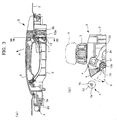
- the operation cable 7 is routed along an extra length securing pathway, as shown in Figs. 1 and 2 .
- the extra length securing pathway is a route that allows the operation cable 7 to be led out from the handle device 5 at the end at which the operation cable 7 is coupled thereto once to the opposite end (front end section), then guided to the rear end section along the side edge of the handle device 5 opposite its side edge where the cable coupling section 11 is disposed, and returned again to the side edge where the cable coupling section 11 is disposed.
- the extra length securing pathway therefore surrounds substantially the entire handle device 5. In this way, even when the relative positions of the handle device 5 and the door lock device 6 change, the operation cable 7 is supplied from the extra length securing pathway and absorbs the positional change, thereby preventing generation of an operation force to the door lock device 6.
- a cable holder 2a is formed at a front end section of the handle base 2 for clamping the operation cable 7 in cooperation with the panel of the door 1, as shown in part (a) of Fig. 3 . Further, a corner section of the base end of the cable holder 2a functions as a guide.
- the operation cable 7 may possibly enter the motion range of the counterweight 8, as shown by broken lines. In this case, the operation cable 7 may be caught on the counterweight 8 when the operation handle 3 is operated, thereby possibly causing an actuation failure.
- the handle base 2 is provided with a guide section 9.
- the guide section 9 is formed in a rectangular plate shape at the periphery on the side where the counterweight 8 is disposed, at an intermediate section between the counterweight 8 and the door lock device 6.
- the guide section 9 guides the operation cable 7 in a direction away from the motion range of the counterweight 8, which is shown by a chain line in Fig. 2 , and therefore ensures prevention of the operation cable 7 from being caught on the counterweight 8.
- the operation cable 7 is guided in a state where it is only supported by the guide section 9.
- the operation cable 7 can be easily slid by load in the axial direction and easily separated from the guide section 9 by load in the vehicle width direction. This eliminates a situation where the guide section 9 restricts movement of the operation cable 7 and blocks the supply of an extra length portion to a dimensionally changed section.
- a plate-shaped guide member 14 is affixed to the door 1 and appropriately shapes the extra length securing pathway. As shown in Fig. 2 , with an elongated guide protrusion 14a, the guide member 14 pushes the side face of the operation cable 7 toward the handle device 5 so that the curvature of the operation cable 7 near the counterweight 8 can be smaller than that in a free state without the guide by the guide section 9. In this way, the operation cable 7 is kept away from the motion range of the counterweight 8.
- the elongated guide protrusion 14a of the guide section 14 only pushes the operation cable 7 and does therefore not restrict the movement of the operation cable 7 in the axial direction or in the vehicle width direction.
Landscapes
- Engineering & Computer Science (AREA)
- Mechanical Engineering (AREA)
- Lock And Its Accessories (AREA)
Claims (5)
- Structure d'acheminement pour câble de fonctionnement, comprenant :un dispositif de la poignée (5), qui est attaché à une porte d'un véhicule (1), et qui émet une force de fonctionnement d'une section de sortie (4), qui est reliée à une poignée de fonctionnement (3), qui est couplée rotative à une base de la poignée (2);un dispositif de verrouillage de porte (6), qui se trouve dans le voisinage de la section de sortie (4) du dispositif de la poignée (5); etun câble de fonctionnement (7), qui couple la section de sortie (4) du dispositif de la poignée (5) et le dispositif de verrouillage de porte (6), caractérisée en ce quele câble de fonctionnement (7) est couplé de la section de sortie (4) au dispositif de verrouillage de porte (6) via une voie de secours d'une longueur supplémentaire, qui encapsule essentiellement le dispositif de la poignée (5), etle câble de fonctionnement (7) est supporté mobile par une section de guidage (9), qui est disposée sur la base de la poignée (2) à une position intermédiaire entre une partie du câble de fonctionnement (7) et une partie mobile (8) du dispositif de la poignée (5), pour être empêché par cela d'entrer dans une amplitude de mouvement de la partie mobile (8), et la partie du câble de fonctionnement (7) est couplée au dispositif de verrouillage de porte (6), dans lequella partie mobile (8) est un contrepoids (8), et un levier (12) et le contrepoids (8) sont couplés à la base de la poignée (2) pivotant autour d'un axe de rotation (12b), et le contrepoids (8) est disposé le long d'un bord latéral de la base de la poignée (2), etun support de câble (2a) est formé à une section de l'extrémité avant de la base de la poignée (2) pour serrer le câble de fonctionnement (7) en conjonction avec le panneau de la porte (1), etla section de guidage (9) est formée dans un plaque rectangulaire à la périphérie sur le côté où le contrepoids (8) est disposé, à une section intermédiaire entre le contrepoids (8) et le dispositif de verrouillage de porte (6).
- Structure d'acheminement pour câble de fonctionnement selon la revendication 1, dans lequel la section de guidage (9) supporte le câble de fonctionnement (7) de sorte que le câble de fonctionnement (7) est capable d'être séparé de la section de guidage (9) lorsqu'il est déplacé vers une direction transversale du véhicule.
- Structure d'acheminement pour câble de fonctionnement selon la revendication 1, dans laquelle un tube poreux (10) est monté sur une section du câble de fonctionnement (7), et la section est supportée par la section de guidage (9).
- Dispositif de la poignée (5), comprenant:une base de la poignée (2), qui est attachée à une porte (1) d'un véhicule;une poignée de fonctionnement (3), qui est couplée de manière rotative à une extrémité de la base de la poignée (2); etune section de sortie (4) avec un contrepoids (8), qui est couplé de manière rotative à un côté de l'autre extrémité de la base de la poignée (2), qui est alimenté par le déplacement d'une tête de la poignée de fonctionnement (3) à la périphérie de sa rotation, et efface une inertie force résultant d'une collision latérale de la porte (1), caractérisé en ce queune section périphérique de la base de la poignée (2) opposant une partie périphérique sur lequel la section de sortie (4) est pivotante agencé est ordonné d'une section d'embrayage de câble (11) à laquelle une extrémité d'un câble de fonctionnement (7) est couplée, qui produit la dislocation de la section de sortie (4), etla section périphérique sur laquelle la section de sortie (4) est pivotante agencé est ordonné d'une section de guidage (9) par laquelle le câble de fonctionnement (7), qui est dirigé pour envelopper essentiellement une périphérie entière de la base de la poignée (2), est supporté de manière mobile afin d'être empêché d'entrer dans une amplitude de mouvement du contrepoids (8), etun levier (12) et le contrepoids (8) sont couplés à la base de la poignée (2) pivotant autour d'un axe de rotation (12b), et le contrepoids (8) est disposé le long d'un bord latéral de la base de la poignée (2) etun support du câble (2a) est formé à une section de l'extrémité avant de la base de la poignée (2) pour serrer le câble de fonctionnement (7) en conjonction avec le panneau de la porte (1), etla section de guidage (9) est formée dans une plaque rectangulaire à la périphérie sur le côté où le contrepoids (8) est disposé, à une section intermédiaire entre le contrepoids (8) et le dispositif de verrouillage de porte (6).
- Dispositif de la poignée (5) selon la revendication 4, dans lequel la section de guidage (9) est formée dans une forme de plaque rectangulaire et, au bord latéral, supporte le câble de fonctionnement (7) de sorte que le câble de fonctionnement (7) est capable d'être séparé de la section de guidage (9) lorsqu'il est déplacé vers une direction transversale du véhicule.
Applications Claiming Priority (2)
| Application Number | Priority Date | Filing Date | Title |
|---|---|---|---|
| JP2013049371A JP6096008B2 (ja) | 2013-03-12 | 2013-03-12 | 操作ケーブルの配索構造 |
| PCT/JP2014/054481 WO2014141869A1 (fr) | 2013-03-12 | 2014-02-25 | Structure d'acheminement pour câble de fonctionnement |
Publications (3)
| Publication Number | Publication Date |
|---|---|
| EP2933406A1 EP2933406A1 (fr) | 2015-10-21 |
| EP2933406A4 EP2933406A4 (fr) | 2016-01-13 |
| EP2933406B1 true EP2933406B1 (fr) | 2017-04-12 |
Family
ID=51536544
Family Applications (1)
| Application Number | Title | Priority Date | Filing Date |
|---|---|---|---|
| EP14764725.9A Active EP2933406B1 (fr) | 2013-03-12 | 2014-02-25 | Structure d'acheminement pour câble de fonctionnement |
Country Status (7)
| Country | Link |
|---|---|
| US (1) | US9333838B2 (fr) |
| EP (1) | EP2933406B1 (fr) |
| JP (1) | JP6096008B2 (fr) |
| KR (1) | KR101798311B1 (fr) |
| CN (1) | CN105074107B (fr) |
| RU (1) | RU2624192C2 (fr) |
| WO (1) | WO2014141869A1 (fr) |
Families Citing this family (11)
| Publication number | Priority date | Publication date | Assignee | Title |
|---|---|---|---|---|
| KR101628499B1 (ko) * | 2014-10-17 | 2016-06-21 | 현대자동차주식회사 | 측면 충돌시 도어 열림이 방지되는 구조 및 그 방법 |
| DK3341542T3 (da) | 2015-08-24 | 2020-08-17 | Dan Raz Ltd | Fastgørelsesmekanisme til et skydepanel |
| US9970214B2 (en) | 2015-11-29 | 2018-05-15 | Dan Raz Ltd | Door or other closable panel with lock-actuating linkage |
| US9988830B2 (en) * | 2016-03-03 | 2018-06-05 | Dan Raz Ltd. | Latch arrangement having a handle |
| US10487545B2 (en) | 2016-03-03 | 2019-11-26 | Dan Raz Ltd. | Latch arrangement having a stop latch |
| DE102016212215A1 (de) * | 2016-07-05 | 2018-01-11 | Volkswagen Aktiengesellschaft | Anordnung zur Verhinderung eines selbsttätigen Öffnens einer Fahrzeugtür oder-klappe sowie Fahrzeug mit einer derartigen Anordnung |
| JP6938132B2 (ja) | 2016-11-07 | 2021-09-22 | 株式会社アルファ | 車両のハンドル装置 |
| JP6963410B2 (ja) * | 2017-05-19 | 2021-11-10 | 株式会社アルファ | 車両のハンドル装置 |
| CN111051631A (zh) | 2017-09-03 | 2020-04-21 | 丹拉斯有限公司 | 闩锁装置 |
| KR102518541B1 (ko) * | 2017-12-01 | 2023-04-07 | 현대자동차주식회사 | 그립 일체형 인사이드핸들 |
| JP6744881B2 (ja) * | 2018-02-20 | 2020-08-19 | 三井金属アクト株式会社 | 自動車用ドアラッチ装置 |
Family Cites Families (19)
| Publication number | Priority date | Publication date | Assignee | Title |
|---|---|---|---|---|
| JPH0443670U (fr) * | 1990-08-20 | 1992-04-14 | ||
| GB2261916A (en) * | 1991-11-30 | 1993-06-02 | Angelo Guerrini | Remotely controlled operation of vehicle doors |
| JP2566840Y2 (ja) * | 1992-09-21 | 1998-03-30 | 日産自動車株式会社 | 自動車用ドアロックと操作装置との連結装置 |
| US5605363A (en) * | 1995-02-07 | 1997-02-25 | Chrysler Corporation | Sliding door latch control assembly |
| ITTO20011000A1 (it) * | 2001-10-19 | 2003-04-19 | Atoma Roltra Spa | Serratura modulare per una portiera di un autoveicolo e portiera provvista di tale serratura. |
| JP4095790B2 (ja) | 2001-11-12 | 2008-06-04 | 株式会社大井製作所 | 車両用ドアのドアロック装置 |
| JP4108455B2 (ja) * | 2002-11-25 | 2008-06-25 | 三井金属鉱業株式会社 | ドアラッチ装置 |
| JP2005035453A (ja) * | 2003-07-17 | 2005-02-10 | Nissan Motor Co Ltd | 車両用ドアのドアロック装置 |
| US7448166B2 (en) * | 2005-02-14 | 2008-11-11 | Toyota Motor Engineering & Manufacturing North America, Inc. | Cable guide mechanism for luggage handles |
| US7568744B2 (en) * | 2005-09-22 | 2009-08-04 | Nissan Technical Center North America, Inc. | Vehicle door handle assembly |
| JP4633599B2 (ja) | 2005-10-28 | 2011-02-16 | 本田技研工業株式会社 | フードロック解除ケーブルの配索構造 |
| US8069616B2 (en) * | 2007-09-07 | 2011-12-06 | Brose Schliesssysteme Gmbh & Co. Kg | Method for mounting a motor vehicle door lock |
| ITMI20071748A1 (it) * | 2007-09-11 | 2009-03-12 | Valeo Sicurezza Abitacolo Spa | Maniglia di sicurezza per veicoli |
| EP2252753B1 (fr) * | 2008-03-13 | 2012-07-25 | Huf Hülsbeck & Fürst GmbH & Co. KG | Poignée extérieure de portière de véhicule équipée d un module de détection |
| US8152209B2 (en) | 2008-03-31 | 2012-04-10 | Illinois Tool Works Inc. | Delay apparatus for opening of vehicle door |
| JP4839467B2 (ja) * | 2008-05-13 | 2011-12-21 | 三井金属アクト株式会社 | 自動車用ドア |
| IT1397430B1 (it) * | 2009-12-11 | 2013-01-10 | Illinois Tool Works | Gruppo maniglia per una porta di veicolo. |
| CN102654004B (zh) * | 2011-03-02 | 2014-12-17 | 布罗斯锁闭系统有限责任两合公司 | 机动车锁 |
| JP5767016B2 (ja) | 2011-05-12 | 2015-08-19 | 株式会社アルファ | 可動部材へのケーブル連結構造 |
-
2013
- 2013-03-12 JP JP2013049371A patent/JP6096008B2/ja active Active
-
2014
- 2014-02-25 KR KR1020157027620A patent/KR101798311B1/ko not_active Expired - Fee Related
- 2014-02-25 RU RU2015139517A patent/RU2624192C2/ru not_active IP Right Cessation
- 2014-02-25 US US14/766,143 patent/US9333838B2/en active Active
- 2014-02-25 WO PCT/JP2014/054481 patent/WO2014141869A1/fr not_active Ceased
- 2014-02-25 CN CN201480010400.9A patent/CN105074107B/zh active Active
- 2014-02-25 EP EP14764725.9A patent/EP2933406B1/fr active Active
Non-Patent Citations (1)
| Title |
|---|
| None * |
Also Published As
| Publication number | Publication date |
|---|---|
| CN105074107A (zh) | 2015-11-18 |
| CN105074107B (zh) | 2018-01-19 |
| RU2015139517A (ru) | 2017-04-17 |
| RU2624192C2 (ru) | 2017-06-30 |
| US9333838B2 (en) | 2016-05-10 |
| KR101798311B1 (ko) | 2017-11-15 |
| WO2014141869A1 (fr) | 2014-09-18 |
| EP2933406A4 (fr) | 2016-01-13 |
| EP2933406A1 (fr) | 2015-10-21 |
| JP6096008B2 (ja) | 2017-03-15 |
| JP2014173385A (ja) | 2014-09-22 |
| KR20150130365A (ko) | 2015-11-23 |
| US20160001643A1 (en) | 2016-01-07 |
Similar Documents
| Publication | Publication Date | Title |
|---|---|---|
| EP2933406B1 (fr) | Structure d'acheminement pour câble de fonctionnement | |
| KR101932807B1 (ko) | 차량용 핸들 장치 | |
| JP5039015B2 (ja) | 車両のドアハンドル装置 | |
| JP4015635B2 (ja) | 車両用ドアハンドル装置 | |
| US20090001734A1 (en) | Door latch apparatus for vehicle | |
| EP2169148B1 (fr) | Dispositif de poignée de porte pour véhicule | |
| WO2012153572A1 (fr) | Structure de liaison de câble pour élément mobile | |
| WO2017078121A1 (fr) | Appareil de verrouillage | |
| JP2013527079A (ja) | 多機能キャリア付き車両ドア | |
| WO2016148181A1 (fr) | Dispositif poignée de portière pour véhicule | |
| JP2013538958A (ja) | 2つのレバーを有する車両用ドアハンドル | |
| JP5764223B2 (ja) | 車両用ドア | |
| JP3839285B2 (ja) | パーキングブレーキ装置 | |
| JP2007106233A (ja) | アームレスト構造 | |
| JP2014073702A (ja) | 車両用シート | |
| JP5926106B2 (ja) | 車両用ドア構造 | |
| EP2687654B1 (fr) | Configuration de poignée | |
| JP6700036B2 (ja) | ケーブル操作構造 | |
| JP4882306B2 (ja) | エンジンフードロック装置 | |
| JP7019334B2 (ja) | ベルクランク装置及びベルクランクユニット | |
| JP2015000681A (ja) | 車両用ポップアップフード装置 | |
| JP4095790B2 (ja) | 車両用ドアのドアロック装置 | |
| JP2017009045A (ja) | 操作レバーとコントロールケーブルの連結構造 | |
| JP2007297002A (ja) | ステアリングコラムの取付構造 | |
| JP2008044412A (ja) | 車両用コンソール装置 |
Legal Events
| Date | Code | Title | Description |
|---|---|---|---|
| PUAI | Public reference made under article 153(3) epc to a published international application that has entered the european phase |
Free format text: ORIGINAL CODE: 0009012 |
|
| 17P | Request for examination filed |
Effective date: 20150716 |
|
| AK | Designated contracting states |
Kind code of ref document: A1 Designated state(s): AL AT BE BG CH CY CZ DE DK EE ES FI FR GB GR HR HU IE IS IT LI LT LU LV MC MK MT NL NO PL PT RO RS SE SI SK SM TR |
|
| AX | Request for extension of the european patent |
Extension state: BA ME |
|
| A4 | Supplementary search report drawn up and despatched |
Effective date: 20151210 |
|
| RIC1 | Information provided on ipc code assigned before grant |
Ipc: E05B 79/22 20140101AFI20151204BHEP Ipc: E05B 77/36 20140101ALI20151204BHEP Ipc: E05B 77/04 20140101ALI20151204BHEP Ipc: E05B 77/06 20140101ALI20151204BHEP Ipc: B60J 5/04 20060101ALI20151204BHEP Ipc: E05B 79/20 20140101ALI20151204BHEP Ipc: E05B 85/16 20140101ALI20151204BHEP |
|
| DAX | Request for extension of the european patent (deleted) | ||
| GRAP | Despatch of communication of intention to grant a patent |
Free format text: ORIGINAL CODE: EPIDOSNIGR1 |
|
| STAA | Information on the status of an ep patent application or granted ep patent |
Free format text: STATUS: GRANT OF PATENT IS INTENDED |
|
| GRAS | Grant fee paid |
Free format text: ORIGINAL CODE: EPIDOSNIGR3 |
|
| INTG | Intention to grant announced |
Effective date: 20170208 |
|
| GRAA | (expected) grant |
Free format text: ORIGINAL CODE: 0009210 |
|
| STAA | Information on the status of an ep patent application or granted ep patent |
Free format text: STATUS: THE PATENT HAS BEEN GRANTED |
|
| AK | Designated contracting states |
Kind code of ref document: B1 Designated state(s): AL AT BE BG CH CY CZ DE DK EE ES FI FR GB GR HR HU IE IS IT LI LT LU LV MC MK MT NL NO PL PT RO RS SE SI SK SM TR |
|
| REG | Reference to a national code |
Ref country code: GB Ref legal event code: FG4D |
|
| REG | Reference to a national code |
Ref country code: CH Ref legal event code: EP |
|
| REG | Reference to a national code |
Ref country code: IE Ref legal event code: FG4D |
|
| REG | Reference to a national code |
Ref country code: AT Ref legal event code: REF Ref document number: 884052 Country of ref document: AT Kind code of ref document: T Effective date: 20170515 |
|
| REG | Reference to a national code |
Ref country code: DE Ref legal event code: R096 Ref document number: 602014008617 Country of ref document: DE |
|
| REG | Reference to a national code |
Ref country code: NL Ref legal event code: MP Effective date: 20170412 |
|
| REG | Reference to a national code |
Ref country code: LT Ref legal event code: MG4D |
|
| REG | Reference to a national code |
Ref country code: AT Ref legal event code: MK05 Ref document number: 884052 Country of ref document: AT Kind code of ref document: T Effective date: 20170412 |
|
| PG25 | Lapsed in a contracting state [announced via postgrant information from national office to epo] |
Ref country code: NL Free format text: LAPSE BECAUSE OF FAILURE TO SUBMIT A TRANSLATION OF THE DESCRIPTION OR TO PAY THE FEE WITHIN THE PRESCRIBED TIME-LIMIT Effective date: 20170412 |
|
| PG25 | Lapsed in a contracting state [announced via postgrant information from national office to epo] |
Ref country code: FI Free format text: LAPSE BECAUSE OF FAILURE TO SUBMIT A TRANSLATION OF THE DESCRIPTION OR TO PAY THE FEE WITHIN THE PRESCRIBED TIME-LIMIT Effective date: 20170412 Ref country code: AT Free format text: LAPSE BECAUSE OF FAILURE TO SUBMIT A TRANSLATION OF THE DESCRIPTION OR TO PAY THE FEE WITHIN THE PRESCRIBED TIME-LIMIT Effective date: 20170412 Ref country code: GR Free format text: LAPSE BECAUSE OF FAILURE TO SUBMIT A TRANSLATION OF THE DESCRIPTION OR TO PAY THE FEE WITHIN THE PRESCRIBED TIME-LIMIT Effective date: 20170713 Ref country code: HR Free format text: LAPSE BECAUSE OF FAILURE TO SUBMIT A TRANSLATION OF THE DESCRIPTION OR TO PAY THE FEE WITHIN THE PRESCRIBED TIME-LIMIT Effective date: 20170412 Ref country code: LT Free format text: LAPSE BECAUSE OF FAILURE TO SUBMIT A TRANSLATION OF THE DESCRIPTION OR TO PAY THE FEE WITHIN THE PRESCRIBED TIME-LIMIT Effective date: 20170412 Ref country code: ES Free format text: LAPSE BECAUSE OF FAILURE TO SUBMIT A TRANSLATION OF THE DESCRIPTION OR TO PAY THE FEE WITHIN THE PRESCRIBED TIME-LIMIT Effective date: 20170412 Ref country code: NO Free format text: LAPSE BECAUSE OF FAILURE TO SUBMIT A TRANSLATION OF THE DESCRIPTION OR TO PAY THE FEE WITHIN THE PRESCRIBED TIME-LIMIT Effective date: 20170712 |
|
| PG25 | Lapsed in a contracting state [announced via postgrant information from national office to epo] |
Ref country code: BG Free format text: LAPSE BECAUSE OF FAILURE TO SUBMIT A TRANSLATION OF THE DESCRIPTION OR TO PAY THE FEE WITHIN THE PRESCRIBED TIME-LIMIT Effective date: 20170712 Ref country code: IS Free format text: LAPSE BECAUSE OF FAILURE TO SUBMIT A TRANSLATION OF THE DESCRIPTION OR TO PAY THE FEE WITHIN THE PRESCRIBED TIME-LIMIT Effective date: 20170812 Ref country code: PL Free format text: LAPSE BECAUSE OF FAILURE TO SUBMIT A TRANSLATION OF THE DESCRIPTION OR TO PAY THE FEE WITHIN THE PRESCRIBED TIME-LIMIT Effective date: 20170412 Ref country code: SE Free format text: LAPSE BECAUSE OF FAILURE TO SUBMIT A TRANSLATION OF THE DESCRIPTION OR TO PAY THE FEE WITHIN THE PRESCRIBED TIME-LIMIT Effective date: 20170412 Ref country code: RS Free format text: LAPSE BECAUSE OF FAILURE TO SUBMIT A TRANSLATION OF THE DESCRIPTION OR TO PAY THE FEE WITHIN THE PRESCRIBED TIME-LIMIT Effective date: 20170412 Ref country code: LV Free format text: LAPSE BECAUSE OF FAILURE TO SUBMIT A TRANSLATION OF THE DESCRIPTION OR TO PAY THE FEE WITHIN THE PRESCRIBED TIME-LIMIT Effective date: 20170412 |
|
| REG | Reference to a national code |
Ref country code: FR Ref legal event code: PLFP Year of fee payment: 5 |
|
| REG | Reference to a national code |
Ref country code: DE Ref legal event code: R097 Ref document number: 602014008617 Country of ref document: DE |
|
| PG25 | Lapsed in a contracting state [announced via postgrant information from national office to epo] |
Ref country code: SK Free format text: LAPSE BECAUSE OF FAILURE TO SUBMIT A TRANSLATION OF THE DESCRIPTION OR TO PAY THE FEE WITHIN THE PRESCRIBED TIME-LIMIT Effective date: 20170412 Ref country code: CZ Free format text: LAPSE BECAUSE OF FAILURE TO SUBMIT A TRANSLATION OF THE DESCRIPTION OR TO PAY THE FEE WITHIN THE PRESCRIBED TIME-LIMIT Effective date: 20170412 Ref country code: DK Free format text: LAPSE BECAUSE OF FAILURE TO SUBMIT A TRANSLATION OF THE DESCRIPTION OR TO PAY THE FEE WITHIN THE PRESCRIBED TIME-LIMIT Effective date: 20170412 Ref country code: EE Free format text: LAPSE BECAUSE OF FAILURE TO SUBMIT A TRANSLATION OF THE DESCRIPTION OR TO PAY THE FEE WITHIN THE PRESCRIBED TIME-LIMIT Effective date: 20170412 Ref country code: RO Free format text: LAPSE BECAUSE OF FAILURE TO SUBMIT A TRANSLATION OF THE DESCRIPTION OR TO PAY THE FEE WITHIN THE PRESCRIBED TIME-LIMIT Effective date: 20170412 |
|
| PGFP | Annual fee paid to national office [announced via postgrant information from national office to epo] |
Ref country code: FR Payment date: 20171215 Year of fee payment: 5 |
|
| PLBE | No opposition filed within time limit |
Free format text: ORIGINAL CODE: 0009261 |
|
| STAA | Information on the status of an ep patent application or granted ep patent |
Free format text: STATUS: NO OPPOSITION FILED WITHIN TIME LIMIT |
|
| PG25 | Lapsed in a contracting state [announced via postgrant information from national office to epo] |
Ref country code: SM Free format text: LAPSE BECAUSE OF FAILURE TO SUBMIT A TRANSLATION OF THE DESCRIPTION OR TO PAY THE FEE WITHIN THE PRESCRIBED TIME-LIMIT Effective date: 20170412 Ref country code: IT Free format text: LAPSE BECAUSE OF FAILURE TO SUBMIT A TRANSLATION OF THE DESCRIPTION OR TO PAY THE FEE WITHIN THE PRESCRIBED TIME-LIMIT Effective date: 20170412 |
|
| 26N | No opposition filed |
Effective date: 20180115 |
|
| PG25 | Lapsed in a contracting state [announced via postgrant information from national office to epo] |
Ref country code: SI Free format text: LAPSE BECAUSE OF FAILURE TO SUBMIT A TRANSLATION OF THE DESCRIPTION OR TO PAY THE FEE WITHIN THE PRESCRIBED TIME-LIMIT Effective date: 20170412 |
|
| REG | Reference to a national code |
Ref country code: CH Ref legal event code: PL |
|
| PG25 | Lapsed in a contracting state [announced via postgrant information from national office to epo] |
Ref country code: MC Free format text: LAPSE BECAUSE OF FAILURE TO SUBMIT A TRANSLATION OF THE DESCRIPTION OR TO PAY THE FEE WITHIN THE PRESCRIBED TIME-LIMIT Effective date: 20170412 |
|
| REG | Reference to a national code |
Ref country code: IE Ref legal event code: MM4A |
|
| REG | Reference to a national code |
Ref country code: BE Ref legal event code: MM Effective date: 20180228 |
|
| PG25 | Lapsed in a contracting state [announced via postgrant information from national office to epo] |
Ref country code: CH Free format text: LAPSE BECAUSE OF NON-PAYMENT OF DUE FEES Effective date: 20180228 Ref country code: LI Free format text: LAPSE BECAUSE OF NON-PAYMENT OF DUE FEES Effective date: 20180228 Ref country code: LU Free format text: LAPSE BECAUSE OF NON-PAYMENT OF DUE FEES Effective date: 20180225 |
|
| PG25 | Lapsed in a contracting state [announced via postgrant information from national office to epo] |
Ref country code: IE Free format text: LAPSE BECAUSE OF NON-PAYMENT OF DUE FEES Effective date: 20180225 |
|
| PG25 | Lapsed in a contracting state [announced via postgrant information from national office to epo] |
Ref country code: BE Free format text: LAPSE BECAUSE OF NON-PAYMENT OF DUE FEES Effective date: 20180228 |
|
| PG25 | Lapsed in a contracting state [announced via postgrant information from national office to epo] |
Ref country code: MT Free format text: LAPSE BECAUSE OF NON-PAYMENT OF DUE FEES Effective date: 20180225 |
|
| PG25 | Lapsed in a contracting state [announced via postgrant information from national office to epo] |
Ref country code: FR Free format text: LAPSE BECAUSE OF NON-PAYMENT OF DUE FEES Effective date: 20190228 |
|
| PG25 | Lapsed in a contracting state [announced via postgrant information from national office to epo] |
Ref country code: TR Free format text: LAPSE BECAUSE OF FAILURE TO SUBMIT A TRANSLATION OF THE DESCRIPTION OR TO PAY THE FEE WITHIN THE PRESCRIBED TIME-LIMIT Effective date: 20170412 |
|
| PGFP | Annual fee paid to national office [announced via postgrant information from national office to epo] |
Ref country code: GB Payment date: 20191205 Year of fee payment: 7 |
|
| PG25 | Lapsed in a contracting state [announced via postgrant information from national office to epo] |
Ref country code: PT Free format text: LAPSE BECAUSE OF FAILURE TO SUBMIT A TRANSLATION OF THE DESCRIPTION OR TO PAY THE FEE WITHIN THE PRESCRIBED TIME-LIMIT Effective date: 20170412 |
|
| PG25 | Lapsed in a contracting state [announced via postgrant information from national office to epo] |
Ref country code: MK Free format text: LAPSE BECAUSE OF NON-PAYMENT OF DUE FEES Effective date: 20170412 Ref country code: HU Free format text: LAPSE BECAUSE OF FAILURE TO SUBMIT A TRANSLATION OF THE DESCRIPTION OR TO PAY THE FEE WITHIN THE PRESCRIBED TIME-LIMIT; INVALID AB INITIO Effective date: 20140225 Ref country code: CY Free format text: LAPSE BECAUSE OF FAILURE TO SUBMIT A TRANSLATION OF THE DESCRIPTION OR TO PAY THE FEE WITHIN THE PRESCRIBED TIME-LIMIT Effective date: 20170412 |
|
| PG25 | Lapsed in a contracting state [announced via postgrant information from national office to epo] |
Ref country code: AL Free format text: LAPSE BECAUSE OF FAILURE TO SUBMIT A TRANSLATION OF THE DESCRIPTION OR TO PAY THE FEE WITHIN THE PRESCRIBED TIME-LIMIT Effective date: 20170412 |
|
| GBPC | Gb: european patent ceased through non-payment of renewal fee |
Effective date: 20210225 |
|
| PG25 | Lapsed in a contracting state [announced via postgrant information from national office to epo] |
Ref country code: GB Free format text: LAPSE BECAUSE OF NON-PAYMENT OF DUE FEES Effective date: 20210225 |
|
| PGFP | Annual fee paid to national office [announced via postgrant information from national office to epo] |
Ref country code: DE Payment date: 20260218 Year of fee payment: 13 |