EP2933423B1 - Vantail de porte - Google Patents
Vantail de porte Download PDFInfo
- Publication number
- EP2933423B1 EP2933423B1 EP15163541.4A EP15163541A EP2933423B1 EP 2933423 B1 EP2933423 B1 EP 2933423B1 EP 15163541 A EP15163541 A EP 15163541A EP 2933423 B1 EP2933423 B1 EP 2933423B1
- Authority
- EP
- European Patent Office
- Prior art keywords
- profile
- frame
- door leaf
- outer profile
- leaf according
- Prior art date
- Legal status (The legal status is an assumption and is not a legal conclusion. Google has not performed a legal analysis and makes no representation as to the accuracy of the status listed.)
- Active
Links
Images

Classifications
-
- E—FIXED CONSTRUCTIONS
- E06—DOORS, WINDOWS, SHUTTERS, OR ROLLER BLINDS IN GENERAL; LADDERS
- E06B—FIXED OR MOVABLE CLOSURES FOR OPENINGS IN BUILDINGS, VEHICLES, FENCES OR LIKE ENCLOSURES IN GENERAL, e.g. DOORS, WINDOWS, BLINDS, GATES
- E06B3/00—Window sashes, door leaves, or like elements for closing wall or like openings; Layout of fixed or moving closures, e.g. windows in wall or like openings; Features of rigidly-mounted outer frames relating to the mounting of wing frames
- E06B3/70—Door leaves
- E06B3/82—Flush doors, i.e. with completely flat surface
- E06B3/822—Flush doors, i.e. with completely flat surface with an internal foursided frame
-
- E—FIXED CONSTRUCTIONS
- E06—DOORS, WINDOWS, SHUTTERS, OR ROLLER BLINDS IN GENERAL; LADDERS
- E06B—FIXED OR MOVABLE CLOSURES FOR OPENINGS IN BUILDINGS, VEHICLES, FENCES OR LIKE ENCLOSURES IN GENERAL, e.g. DOORS, WINDOWS, BLINDS, GATES
- E06B3/00—Window sashes, door leaves, or like elements for closing wall or like openings; Layout of fixed or moving closures, e.g. windows in wall or like openings; Features of rigidly-mounted outer frames relating to the mounting of wing frames
- E06B3/70—Door leaves
- E06B2003/7059—Specific frame characteristics
-
- E—FIXED CONSTRUCTIONS
- E06—DOORS, WINDOWS, SHUTTERS, OR ROLLER BLINDS IN GENERAL; LADDERS
- E06B—FIXED OR MOVABLE CLOSURES FOR OPENINGS IN BUILDINGS, VEHICLES, FENCES OR LIKE ENCLOSURES IN GENERAL, e.g. DOORS, WINDOWS, BLINDS, GATES
- E06B3/00—Window sashes, door leaves, or like elements for closing wall or like openings; Layout of fixed or moving closures, e.g. windows in wall or like openings; Features of rigidly-mounted outer frames relating to the mounting of wing frames
- E06B3/70—Door leaves
- E06B2003/7059—Specific frame characteristics
- E06B2003/708—Specific frame characteristics insulated
-
- Y—GENERAL TAGGING OF NEW TECHNOLOGICAL DEVELOPMENTS; GENERAL TAGGING OF CROSS-SECTIONAL TECHNOLOGIES SPANNING OVER SEVERAL SECTIONS OF THE IPC; TECHNICAL SUBJECTS COVERED BY FORMER USPC CROSS-REFERENCE ART COLLECTIONS [XRACs] AND DIGESTS
- Y02—TECHNOLOGIES OR APPLICATIONS FOR MITIGATION OR ADAPTATION AGAINST CLIMATE CHANGE
- Y02B—CLIMATE CHANGE MITIGATION TECHNOLOGIES RELATED TO BUILDINGS, e.g. HOUSING, HOUSE APPLIANCES OR RELATED END-USER APPLICATIONS
- Y02B10/00—Integration of renewable energy sources in buildings
- Y02B10/10—Photovoltaic [PV]
-
- Y—GENERAL TAGGING OF NEW TECHNOLOGICAL DEVELOPMENTS; GENERAL TAGGING OF CROSS-SECTIONAL TECHNOLOGIES SPANNING OVER SEVERAL SECTIONS OF THE IPC; TECHNICAL SUBJECTS COVERED BY FORMER USPC CROSS-REFERENCE ART COLLECTIONS [XRACs] AND DIGESTS
- Y02—TECHNOLOGIES OR APPLICATIONS FOR MITIGATION OR ADAPTATION AGAINST CLIMATE CHANGE
- Y02E—REDUCTION OF GREENHOUSE GAS [GHG] EMISSIONS, RELATED TO ENERGY GENERATION, TRANSMISSION OR DISTRIBUTION
- Y02E10/00—Energy generation through renewable energy sources
- Y02E10/50—Photovoltaic [PV] energy
Definitions
- the invention relates to a door leaf comprising a frame with at least two longitudinal frame elements and at least one cover layer.
- the EP 1 918 501 A1 discloses a partition member of a room having a first panel facing an inside of the room and a second panel facing an outside of the room, the panels being fixedly connected peripherally to a frame.
- the frame comprises a first part which is movable relative to a second part, the first part having at least two degrees of freedom in a plane substantially parallel to the coverings.
- the first part of the frame is formed by a thermal break interrupting member and comprises a plastic profile having one end mounted with play in a receptacle formed on the second part of the frame or on an intermediate member between the first and second part of the frame.
- WO 2006/104383 A1 a door leaf with a frame comprising two longitudinal frame members, wherein in one of the frame members openings for insertion of function carriers, which are formed on the one hand as an electric lock and the other as an electronic component. having.
- US 2010/0269450 A1 a door leaf with a frame comprising two longitudinal frame members between which a functional element is arranged, which spans substantially the inner surface formed by the frame.
- the frame can be formed as a sash and pivot or fixed. If it is a frame with a non-transparent filling in a building wall, in particular an outer wall, an insulating layer is often present in the filling.
- the frame supports an inner and / or outer cover layer, which is arranged either covering between the frame parts or the frame parts.
- the cover layer can be made arbitrarily functional and / or visually appealing and covers, for example, the filling.
- the frame carries an inner and / or outer cover layer, which is arranged either overlapping between the frame parts or the frame parts.
- the cover layer can be made arbitrarily functional and / or visually appealing and covers, for example, the filling.
- the invention has for its object to provide a framework of the type mentioned, having additional functionalities. According to the invention the object is solved by the features of independent claim 1.
- a preferred use of the door is at a front door or apartment door.
- the function carrier may itself have a functionality or be designed as a holder or fastening device for additional components. Since the function carrier is located within the frame and covered by the filling for the most part, it does not interfere with the perceptible to a viewer visual impression of the door or the window.
- the function carrier can for example take over the frame stiffening functions or support a device for observing the environment. Further preferred Variants are shown below.
- the cover layer may be transparent or translucent, for example, at least in certain areas and opaque in other areas. It is also conceivable to make the entire cover layer transparent or translucent or opaque.
- the filling is, for example, in regions in which optical functional elements are arranged, either cut free or transparent, so that the optically acting functional element can develop its intended effect.
- the function carrier spans at least the inner surface formed by the frame or is attached like a tongue to one of the frame elements or arranged in a bar-shaped manner between two frame elements.
- the size of the function carrier is limited only by the size of the frame and at least large enough that a functional element to be arranged within the frame, for example a temperature sensor or a microphone or the like, can be reliably fastened.
- the function carrier on frame-side retaining strips or mounting flanges or mounting straps can be fixed non-positively or positively or cohesively.
- the function carrier for storing heat or cold or as insulation against sound, heat, cold, radiation and / or pollutants is formed.
- These functionalities substantially increase the comfort for the occupants of an apartment which is closed, for example, by means of a corresponding door.
- the function carrier is preferably resistant to bombardment or burglary or fire.
- the function carrier may be plate-shaped and extend substantially over the entire frame.
- a security-relevant function carrier without the formation of gaps between the function carrier and the frame reliably fixed to withstand a large force.
- the function carrier can be made of plastics or metals or compounds of these materials.
- the function carrier is assigned at least one electrical or electromechanical functional element.
- the functional element can be arranged, for example, on the above-described function carrier, of course, together with other functional elements.
- the functional element may be, for example, a transmitter communicating with a remote receiver.
- a motor-operated partial opening such as a ventilation flap or pet door, which opens and closes automatically, for example due to a temperature and / or air quality sensor signal or a transponder signal or a remote control signal is conceivable arrangement.
- the flap itself may preferably be pivotally mounted on the function carrier or on a filling or the cover layer and the associated motor is fastened together with the receiver for the transponder signal to the function carrier.
- the functional element is expediently designed as a photovoltaic element that is coupled to a further electrical and / or electromechanical functional element for storing electrical energy and / or for supplying electrical energy. Accordingly, the photovoltaic element can supply voltage to functional elements arranged on the function carrier, and a feed line or battery is essentially dispensable.
- the functional element is preferably designed as a sensor or actuator, in particular as a sensor of an image capture device or a toner detection or Tonvertergabe friendship or a position sensor or a vibration sensor or fingerprint recognition sensor, or an actuator of a locking system or a locking device.
- a fingerprint recognition sensor may be assigned to the function carrier, which comprises an evaluation device and a memory device for fingerprints, and which, when a stored fingerprint is detected, actuates one to open a locking device.
- a motor for pivoting the frame, respectively the door can be provided.
- the outer cover layer is so transparent or cut out in the region of the image capture device that it is possible to record the outer region of the image capture device, which is preferably coupled directly to the cover view.
- the image capture device comprises a corresponding image sensor, which may be miniaturized and installed with an associated optical device. Also in the area of the fingerprint recognition sensor, it is necessary to form the cover layer correspondingly for the detection of a fingerprint.
- the functional element is designed as a visually or audibly perceptible signal element and preferably connected to an alarm system.
- the signal element can be, for example, a lighting element or a siren which is assigned to the function carrier and is activated or activated by the alarm system. Sonach can light up the entire door leaf, for example, in an alarm and appropriate design of the signal element.
- the data connection between the sensors / actuators and a computer device is ensured by means of a data transmission device arranged within the frame.
- a data transmission device arranged within the frame.
- the sensors and / or the actuators are expediently connected to a data processing device of a home automation device.
- Each of the frame members comprises an inner profile oriented toward a room side and an outer profile oriented toward an outer side, wherein the inner profile is positively connected to the outer profile such that the inner profile is displaceable relative to the outer profile in the direction of a longitudinal axis. Since the connection between the outer profile and the inner profile allows a relative movement in the direction of the longitudinal axis of the two profiles having the greatest length changes, the inner profile is decoupled from the outer profile, whereby stresses due to a thermally induced change in length and associated changes in shape are avoided or substantially reduced are.
- a slidable in the direction of the longitudinal axis clip connection is provided between the inner profile and the outer profile.
- the outer profile on two spaced apart clip arms, which cooperate with undercuts of the inner profile, wherein the inner profile is formed as a rectangular in cross-section hollow chamber profile having at its one broad side the undercuts.
- the outer profile and the inner profile can be produced in a drawing or extrusion process, for example of an aluminum alloy or a plastic. Because of the uniaxial decoupling, so the displacement in the direction of the longitudinal axis, the similarity of the coefficients of linear expansion is only of minor importance, it is possible, for example, the inner profile made of an aluminum alloy and the outer profile of a plastic or vice versa.
- the undercuts may be substantially integrated into the inner profile, be designed as a kind Klipsnasen, or as Gegenklipsarme, which extend away from the inner profile.
- the outer profile is formed as a cross-sectionally L-shaped hollow profile and has at its long leg on the spaced clip arms.
- the outer profile is arranged such that it faces outward with the free end face of its short leg, and the long leg is aligned parallel to the inner profile. Accordingly, the outwardly facing surface of the short leg is relatively small, which has a positive effect on the heat transfer, and the outwardly facing surface of the long leg, which faces the Klipsarme having surface, for example, can serve to support a surface heat insulation.
- the function carrier is fixed on the long leg of the outer profile.
- the function carrier can be screwed to the outer profile, riveted, glued or the like non-positively or positively connected.
- the outer profile has in its short leg a receiving groove for a terminal block for fixing the function carrier on the long leg.
- a terminal block for fixing the function carrier on the long leg.
- the terminal strip may be a known from the prior art glass retaining strip or other holder that fixes the function carrier on the long leg of the outer profile.
- the outer profile on a frame outer side profile end face on at least one over the entire length extending convex sealing curvature.
- the sealing curvature is provided for abutment against a sealing rubber and in particular may comprise two side by side formed sealing curvatures, which are mounted in one State of serving as a sash of a door frame extending into a door gap.
- spacer lugs are preferably arranged between the clip arms. For example, if two rib-shaped spacer lugs formed on the outer profile and is located between these spacer lugs formed on the inner profile rib-like spacer nose, then the outer profile against the inner profile against a lateral displacement, which does not correspond to the longitudinal direction, secured.
- the inner profile on its side opposite the broad side with the undercuts broadside on a frame outer side profile end admirably fits into a frame outer side profile end admirably holds a seal with a groove.
- the projection forms a kind of fold, which is formed on the inner profile, With a mounted against a frame fitting seal an additional sealing layer is created, which causes an improvement in the heat transfer coefficient (U-value) and a reduction in air permeability in the convection zone of the door rebate wherein a first seal acts on the outside between the frame and the door leaf formed by sash and filling.
- At least one sliding in the direction of the longitudinal axis tongue and groove connection is provided between the inner profile and the outer profile.
- the tongue and groove connection in cross-section T-shaped or dovetail-shaped.
- the T-slot or dovetail connection between the inner profile and the outer profile also allow a relative movement of these two profiles in the direction of the longitudinal axis, whereby, given a different change in length of the two profiles, in particular due to different temperatures on the outside and the inside, an undesired deformation over the length is avoided or substantially reduced.
- the clip connection or the tongue and groove connection is preferably associated with the longitudinal frame members.
- this is associated with a longitudinal side frame member of a closing side and the other longitudinal side frame member of a hinge side.
- a longitudinal side frame member of a closing side and the other longitudinal side frame member of a hinge side.
- this can be attached to the corresponding inner profiles bands or closing elements.
- the filling is fixed on the outside and / or the inside of the frame elements.
- the filling or its cover layer is fixed on the free end face of the short leg of the outer profile, so that a heat transfer surface is dimensioned relatively small in this area.
- the filling covers the frame, which is therefore not visible to a viewer in a closed door, which is why the frame profiles can be made of any materials or material combinations that do not interfere visually.
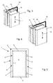
- a door 1 comprises a door leaf 2, which is essentially composed of a frame 3 with an associated filling 4, wherein the filling 4 in the present case comprises an outer cover layer 5 and an inner cover layer 6 and an insulating layer 7 arranged between the cover layers for thermal insulation.
- the frame 3 has two longitudinal frame members 8 and two wide-sided frame members 9 which are each connected at right angles, wherein the one longitudinal frame member 8 a closing side 10 and the other longitudinal side Frame element 8 a hinge side 11 of the door 1 is assigned.
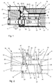
- Each of the longitudinal frame members 8 is composed of an inner profile 12 and a non-positively or positively connected thereto outer profile 13 that the inner profile 12 relative to the outer profile 13 in the direction of a longitudinal axis according to the double arrow 14 is displaceable.
- the inner profile 12 on the band side 11 is fixedly connected to one end of a band 15 whose other end is coupled to a frame 16, which is composed essentially of a mecaniczargenhohlprofil 17 and a explicatenzargenhohlprofil 18 with a disposed therebetween thermal separation profile 19.
- the mecaniczargenhohlprofil 17 is firmly pressed with the separation profile 19 and the separation profile 19 with the outer frame hollow profile 18.
- the different elongations of the outer profile 13 and the inner profile 12 of the longitudinal frame members 8 result, between the outer profile 13 and the inner profile 12 clip connections 20th , which fix the outer profile 13 relative to the inner profile 12 in two axes and allow movement in one axis according to the double arrow 14.
- the clip connections are only exemplary embodiments of such a connection with a degree of freedom. It is also possible to realize, for example, a tongue and groove joint in T-shape or dovetail shape or the like to achieve the same effect.
- the outer profile 13 is formed as a cross-sectionally L-shaped hollow section with a long leg 21 and a short leg 22 extending at right angles thereto.
- the short leg 22 of the outer profile 13 extends in the frame 16 and the free end face forms a support for the outer cover layer 5 of the filling 4.
- the short leg 22 associated with a sealing curvature 47.
- the long leg 21 of the outer profile 13 is aligned parallel to the rectangular profile in cross-section hollow profile of the inner profile 12 and extends by means formed on the outer profile 13 spacer lugs 23 spaced from a broad side 24 of the inner profile 12.
- the outer profile 13 facing broad side of 24 of the inner profile 12 has hook-shaped undercuts 25 which cooperate with integrally formed on the outer profile 13 Kbrirmen 26.
- the hook-shaped undercuts 25 may alternatively be formed in the form of Gegenk redesignrmen 27 on the inner profile 12.
- a spacer cam 29 which rests against the outer profile 13.
- the wide side 24 with the undercuts 25 opposite broad side 30 of the inner profile 12 has a beyond the frame outer side profile end 28 überersteckenden extension 31 which forms a fold with the profile end face 28 and for holding an inside seal 32, which is in the closed state of the door 1 supported on the frame 16, is provided with a groove 33.
- the extension 31 and the corresponding broad side 30 of the inner profile 12 are spanned by the inner cover layer 6.
- On the outside of the door 1 of the frame 16 is associated with a circumferential seal 34 which rests biased in the closed state of the door 1 on the outer cover layer 5 of the filling 4.
- the outer profile 13 undergoes a reduced in relation to the inner profile 12 elongation, at a fixed connection, as of a Bimetallic known, leading to a curvature towards the outside of the door 1. Due to the connection with the one degree of freedom in the direction of the longitudinal axis of the frame 3, a displacement of the inner profile 12 takes place relative to the outer profile 13, as can be seen in Fig ..
- a resting on the long leg 21 of the outer profile 13 function carrier 35 is arranged, which can be screwed or glued to the outer profile 13. It is also possible to additionally or alternatively fix the function carrier 35 to the long leg 21 of the outer profile 13 in a force-fitting manner, for which purpose the outer profile 13 has a receiving groove 36 in its short leg 22 for a clamping strip 37 which is known from the prior art Glashaltemann acts and is attached.
- the function carrier 35 may, for example, extend over the entire inner surface of the door leaf 2 and have heat-insulating and / or sound-insulating and / or burglary-resistant and / or bullet-proof properties. It is additionally or alternatively possible, the function carrier 35 function elements 38 actuators 39, for example, a locking mechanism, and / or sensors 40, for example, an image and / or toner detection device to assign.
- the actuators 39 and sensors 40 can be via appropriate Interfaces, which may also be arranged on the planar function carrier 35, wirelessly or wired to a computer of a data processing device, preferably a home controller, connect via a data transmission device 41.
- the data transmission device 41 may be assigned a computer module 45 with a memory module 46.
- one of the actuators 39 is designed as a motor 42, which serves for pivoting the door 1.
- Another actuator 39 is a shutter motor 43, which cooperates with a locking mechanism of the door 1.
- an image detection device 44 is provided as the sensor 40, which cooperates on the one hand with a face and / or eye detection in order to open the door 1 to an authorized person by activating the motor 42 and / or the shutter motor 43.
- An environment of the door 1 can also be represented by means of the image capture device 44 connected to a display device via the data transfer device 41.
- An image acquisition sensor to which an optical device, for example a lens or a lens, can be assigned, is arranged in a transparent or cut-out region, in particular the outer cover layer 5.
- a fingerprint recognition sensor sensor 40 is installed such that it is freely accessible, for example, in the outer cover layer 5.
- a microphone is fixed to the function carrier 35 in a region in which the outer cover layer 5 is perforated.
- the areas of the cover layer 5, 6, which must have a special functionality for the associated sensors 40, are preferably designed such that this functionality, such as a transparency or perforation, is visually imperceptible to a viewer, or does not interfere visually , reference numeral 1.
Landscapes
- Engineering & Computer Science (AREA)
- Civil Engineering (AREA)
- Structural Engineering (AREA)
- Special Wing (AREA)
- Securing Of Glass Panes Or The Like (AREA)
- Wing Frames And Configurations (AREA)
- Specific Sealing Or Ventilating Devices For Doors And Windows (AREA)
Claims (13)
- Ventail de porte comprenant un cadre (3) ayant au moins deux éléments de cadre longitudinaux (8) et au moins une couche de couverture (5, 6), dans lequel- chacun des éléments de cadre comprend un profil intérieur orienté vers un côté intérieur et un profil extérieur orienté vers un côté extérieur,- le profil intérieur (12) est relié par complémentarité de forme au profil extérieur (13) de manière à ce que le profil intérieur puisse être décalé par rapport au profil extérieur (13) dans la direction d'un axe longitudinal (double flèche 14),caractérisé en ce que- le profil extérieur (13) est réalisé sous la forme d'un profil de chambre creuse ayant la forme d'un L en section transversale présentant une branche longue (21) et une branche courte (22) s'étendant à angle droit par rapport à celle-ci, dans lequel une face avant libre de la branche courte (22) forme un point d'appui pour la couche de couverture extérieure (5) d'une garniture (4), et- un support fonctionnel (35) reposant sur la branche longue (21) du profil extérieur (13) et revêtu dans les parties essentielles par la couche de couverture (5, 6), qui est fixé au profil extérieur (13) à l'emplacement de la branche longue (21) du profil extérieur (13), le profil extérieur (13) présentant à cet effet dans sa branche courte (22) une rainure de réception (36) destinée à une barre de serrage (37) permettant de fixer le support fonctionnel (35) à la branche longue (21).
- Ventail de porte selon la revendication 1, caractérisé en ce que le support fonctionnel (35) enjambe au moins la surface intérieure formée par le cadre (3) et est fixé à la manière d'une patte à l'un des éléments de cadre (8) ou est disposé à la manière d'une traverse entre les éléments de châssis (8).
- Ventail de porte selon la revendication 1 ou 2, caractérisé en ce que le support fonctionnel (35) est réalisé de manière à accumuler de la chaleur ou sous la forme d'un blindage contre le son, la chaleur, les rayonnements ou les contaminants ou en ce qu'il est réalisé de manière durable afin de résister au tir ou aux effractions ou au feu.
- Ventail de porte selon l'une quelconque des revendications 1 à 3, caractérisé en ce qu'au moins un élément fonctionnel (38) électrique ou électromécanique est associé au support fonctionnel (35).
- Ventail de porte selon la revendication 4, caractérisé en ce que l'élément fonctionnel (38), dans le cas d'une garniture (4) transparente aux rayonnements lumineux, est réalisé sous la forme d'un élément photovoltaïque qui est couplé à un autre élément fonctionnel (38) électrique ou électromécanique pour accumuler de l'énergie électrique ou pour délivrer de l'énergie électrique.
- Ventail de porte selon la revendication 4 ou 5, caractérisé en ce que l'élément fonctionnel (38) est réalisé sous la forme d'un capteur (40) et/ou d'un actionneur (39), notamment sous la forme d'un capteur (40) d'un dispositif d'acquisition d'image (44) ou d'un dispositif de détection de fréquence vocale ou de restitution de fréquence vocale ou d'un capteur de position ou d'un capteur de choc ou d'un capteur de reconnaissance d'empreinte digitale, ou d'un actionneur (39) d'une installation de fermeture ou d'un dispositif de verrouillage, dans lequel les capteurs (40) et/ou les actionneurs (39) sont reliés à un dispositif de traitement de données d'un dispositif de domotique, ou l'élément fonctionnel (38) est conçu sous la forme d'un élément générateur de signal perceptible optiquement et/ou acoustiquement et de préférence relié à un système d'alarme.
- Ventail de porte selon la revendication 1, caractérisé en ce qu'un dispositif de transmission de données (41) est disposé à l'intérieur du cadre (3).
- Ventail de porte selon la revendication 1, caractérisé en ce qu'il est prévu une liaison de clipsage (20) pouvant être décalée dans la direction de l'axe longitudinal (double flèche 14) entre le profil intérieur (12) et le profil extérieur (13).
- Ventail de porte selon la revendication 8, caractérisé en ce que la branche longue (21) du profil extérieur (13) présente sur l'une de ses faces des bras de clipsage (26) mutuellement espacés, et sur la face opposée, est utilisée en tant que point d'appui du support fonctionnel (35), dans lequel les bras de clipsage (26) coopèrent avec des contre-dépouilles (25) du profil intérieur (12) réalisé sous la forme d'un profil de chambre creuse rectangulaire en section transversale.
- Ventail de porte selon l'une quelconque des revendications 1 à 9, caractérisé en ce que le profil extérieur (13) présente, sur une face avant de profil (28) située du côté extérieur au cadre, un bombement en épaisseur (47) convexe s'étendant sur la totalité de la longueur.
- Ventail de porte selon la revendication 1, caractérisé en ce que le profil intérieur (12) présente, sur son côté large (30) opposé à un côté large (24) présentant les contre-dépouilles (25), une saillie (31) pénétrant par l'intermédiaire d'une face avant de profil intérieur (28) située du côté extérieur au cadre, laquelle saillie est munie d'une rainure (33) destinée à supporter un joint (32).
- Ventail de porte selon la revendication 1, caractérisé en ce qu'il est prévu entre le profil intérieur (12) et le profil extérieur (13) au moins une liaison par rainure et languette pouvant être décalée dans la direction de l'axe longitudinal (double flèche 14), qui est réalisée de manière à présenter la forme d'un T ou une forme de queue d'aronde en section transversale.
- Ventail de porte selon la revendication 8 ou 12, caractérisé en ce que la liaison de clipsage (20) ou la liaison par rainure et languette est associée aux éléments de cadre longitudinaux (8), dans lequel l'un des éléments de cadre longitudinaux (8) est associé à une face de fermeture (10) et l'autre des éléments de cadre longitudinaux (8) est associé à un côté formant charnière (11).
Applications Claiming Priority (1)
| Application Number | Priority Date | Filing Date | Title |
|---|---|---|---|
| DE102014105388.5A DE102014105388B4 (de) | 2014-04-15 | 2014-04-15 | Türflügel einer Tür |
Publications (2)
| Publication Number | Publication Date |
|---|---|
| EP2933423A1 EP2933423A1 (fr) | 2015-10-21 |
| EP2933423B1 true EP2933423B1 (fr) | 2016-11-16 |
Family
ID=52875031
Family Applications (1)
| Application Number | Title | Priority Date | Filing Date |
|---|---|---|---|
| EP15163541.4A Active EP2933423B1 (fr) | 2014-04-15 | 2015-04-14 | Vantail de porte |
Country Status (2)
| Country | Link |
|---|---|
| EP (1) | EP2933423B1 (fr) |
| DE (1) | DE102014105388B4 (fr) |
Cited By (1)
| Publication number | Priority date | Publication date | Assignee | Title |
|---|---|---|---|---|
| FR3150830A1 (fr) * | 2023-07-05 | 2025-01-10 | Groupe Liebot | Ouvrant pour une menuiserie, par exemple une porte, destinée à équiper une baie de bâtiment |
Families Citing this family (5)
| Publication number | Priority date | Publication date | Assignee | Title |
|---|---|---|---|---|
| CA2916964C (fr) | 2016-01-08 | 2018-02-27 | 9519785 Canada Inc. | Sceau d'etancheite a fixation magnetique |
| BE1025306B1 (nl) * | 2017-02-14 | 2019-01-17 | B'tween Cvba | Verbeterde deurvleugel voor een buitendeur |
| EP3412857A1 (fr) * | 2017-06-06 | 2018-12-12 | Hörmann KG Eckelhausen | Battant de porte d'une porte d'entrée et procédé de fabrication correspondant |
| DE102017005795A1 (de) * | 2017-06-21 | 2018-12-27 | Thiem Security Solutions Gmbh | Klima- und Präzisionstür |
| CN116163625B (zh) * | 2021-07-16 | 2025-08-19 | 泉州市盛发安防发展有限公司 | 便于安装的防火门的门框 |
Family Cites Families (14)
| Publication number | Priority date | Publication date | Assignee | Title |
|---|---|---|---|---|
| DE525520C (de) * | 1931-05-26 | Struthfabrik G M B H | Hohltuer | |
| GB2258683B (en) * | 1991-08-14 | 1995-04-05 | Hsieh Wu Chang | Door panel |
| DE29505223U1 (de) * | 1995-03-15 | 1995-06-01 | Lilge, Helmut, 94469 Deggendorf | Türflügel für Gebäudeaußentür |
| GB9823214D0 (en) * | 1998-10-26 | 1998-12-16 | Autoplas International Limited | Panel construction |
| US20050102967A1 (en) * | 2003-10-30 | 2005-05-19 | Louis Abdo | Versatile panel with internal extruded profiles |
| NL1028680C2 (nl) * | 2005-04-01 | 2006-10-12 | Caio | Deur omvattende een identificatieeenheid en een electrisch slot en deurlichaam voor gebruik in een dergelijke deur. |
| FR2891576B1 (fr) * | 2005-10-04 | 2007-12-21 | Zilten Soc Par Actions Simplif | Procede de realisation d'un panneau anti-effraction, tel qu'un ouvrant de porte, d'obturation d'une ouverture exterieure de batiment, et panneau anti-effraction realise. |
| DE102006046563A1 (de) * | 2006-03-01 | 2007-09-06 | BRÜCKNER, Rolf | Solartür |
| FR2908150B1 (fr) * | 2006-11-02 | 2013-01-11 | Lapeyre | Element de separation d'un local |
| DE102009032040A1 (de) * | 2009-04-06 | 2010-10-07 | Hörmann KG Eckelhausen | Haustür mit faserverstärktem Kunststoffmaterial sowie Herstellverfahren |
| US8516756B2 (en) * | 2009-04-27 | 2013-08-27 | Secura-Seal Technologies Llc | Door panel with thermal break |
| WO2011152569A1 (fr) * | 2010-05-31 | 2011-12-08 | 코오롱건설주식회사 | Verre multicouche et module photovoltaïque intégré à la construction l'incluant |
| DE202011000669U1 (de) | 2011-03-23 | 2012-06-26 | Zoran Sencar | Schichtaufbau für Türblatt |
| DE102011053210A1 (de) * | 2011-09-02 | 2013-03-07 | Dorma Gmbh + Co. Kg | Tür, wenigstens teilweise aus Glas |
-
2014
- 2014-04-15 DE DE102014105388.5A patent/DE102014105388B4/de active Active
-
2015
- 2015-04-14 EP EP15163541.4A patent/EP2933423B1/fr active Active
Cited By (1)
| Publication number | Priority date | Publication date | Assignee | Title |
|---|---|---|---|---|
| FR3150830A1 (fr) * | 2023-07-05 | 2025-01-10 | Groupe Liebot | Ouvrant pour une menuiserie, par exemple une porte, destinée à équiper une baie de bâtiment |
Also Published As
| Publication number | Publication date |
|---|---|
| DE102014105388B4 (de) | 2026-03-26 |
| EP2933423A1 (fr) | 2015-10-21 |
| DE102014105388A1 (de) | 2015-10-15 |
Similar Documents
| Publication | Publication Date | Title |
|---|---|---|
| EP2933423B1 (fr) | Vantail de porte | |
| CA2884931C (fr) | Systeme de fenetre et de porte a structure pouvant etre facilement changee | |
| US20100281779A1 (en) | Reversible sliding glass door | |
| AT510842B1 (de) | Türvorrichtung für ein tier | |
| EP2933422B1 (fr) | Vantail de porte | |
| EP3617430B1 (fr) | Dispositif de verrouillage pour portes coulissantes | |
| EP2933418B1 (fr) | Encadrement pour une porte ou une fenêtre avec câblage électrique | |
| EP2213826B1 (fr) | Battant de fenêtre composite pour fenêtres et portes-fenêtres dotées d'un profil de pied correspondant | |
| EP2951378B1 (fr) | Ensemble de panneaux de volet pour ouvertures architecturales | |
| DE202009000363U1 (de) | Fenster mit integriertem Insekten- und/oder Pollenschutz | |
| DE102019120198A1 (de) | Kasten zur Aufnahme eines Rollladens oder eines Sonnenschutzes und Fenster oder Tür | |
| KR101553518B1 (ko) | 창호용 방풍구 | |
| DE102009004352A1 (de) | Wärmegedämmte Wandelementeinheit für Gebäudefassaden | |
| US20210293084A1 (en) | Garage Door Blind Assembly | |
| DE102017005061B4 (de) | Auswertelogik für Sensoren von Öffnungszuständen von Fenstern und Türen | |
| DE202007002705U1 (de) | Schließelement für eine Wandöffnung, insbesondere Tür für eine Zugangsöffnung in ein Haus | |
| DE102007030386A1 (de) | Antrieb für eine Tür oder ein Fenster | |
| DE29809053U1 (de) | Öffnungsrahmen für Fenster und Türen | |
| DE3042041A1 (de) | Fensterladen | |
| SU969870A1 (ru) | Створный элемент светопрозрачного ограждени | |
| KR20160104907A (ko) | 창호 보수용 방풍 및 방충레일 | |
| DE29922952U1 (de) | Rahmen- oder Zusatzprofil aus Metall zur Herstellung von Fenstern oder Türen | |
| DE202023102787U1 (de) | Einsatz oder Aufsatz für ein Fenster zur Wärme- und Lautstärkendämmung | |
| DE102021006276A1 (de) | Mehrscheibenglassensoranordnung | |
| DE202010016652U1 (de) | Mit Vakuum-Isolations-Paneel beplankte Vorbaurollladen |
Legal Events
| Date | Code | Title | Description |
|---|---|---|---|
| PUAI | Public reference made under article 153(3) epc to a published international application that has entered the european phase |
Free format text: ORIGINAL CODE: 0009012 |
|
| AK | Designated contracting states |
Kind code of ref document: A1 Designated state(s): AL AT BE BG CH CY CZ DE DK EE ES FI FR GB GR HR HU IE IS IT LI LT LU LV MC MK MT NL NO PL PT RO RS SE SI SK SM TR |
|
| AX | Request for extension of the european patent |
Extension state: BA ME |
|
| 17P | Request for examination filed |
Effective date: 20160412 |
|
| RBV | Designated contracting states (corrected) |
Designated state(s): AL AT BE BG CH CY CZ DE DK EE ES FI FR GB GR HR HU IE IS IT LI LT LU LV MC MK MT NL NO PL PT RO RS SE SI SK SM TR |
|
| GRAP | Despatch of communication of intention to grant a patent |
Free format text: ORIGINAL CODE: EPIDOSNIGR1 |
|
| RIC1 | Information provided on ipc code assigned before grant |
Ipc: E06B 3/82 20060101AFI20160510BHEP Ipc: E06B 3/70 20060101ALI20160510BHEP |
|
| INTG | Intention to grant announced |
Effective date: 20160614 |
|
| GRAS | Grant fee paid |
Free format text: ORIGINAL CODE: EPIDOSNIGR3 |
|
| GRAA | (expected) grant |
Free format text: ORIGINAL CODE: 0009210 |
|
| AK | Designated contracting states |
Kind code of ref document: B1 Designated state(s): AL AT BE BG CH CY CZ DE DK EE ES FI FR GB GR HR HU IE IS IT LI LT LU LV MC MK MT NL NO PL PT RO RS SE SI SK SM TR |
|
| REG | Reference to a national code |
Ref country code: GB Ref legal event code: FG4D Free format text: NOT ENGLISH |
|
| REG | Reference to a national code |
Ref country code: CH Ref legal event code: EP |
|
| REG | Reference to a national code |
Ref country code: IE Ref legal event code: FG4D Free format text: LANGUAGE OF EP DOCUMENT: GERMAN |
|
| REG | Reference to a national code |
Ref country code: AT Ref legal event code: REF Ref document number: 846134 Country of ref document: AT Kind code of ref document: T Effective date: 20161215 |
|
| REG | Reference to a national code |
Ref country code: DE Ref legal event code: R096 Ref document number: 502015000297 Country of ref document: DE |
|
| REG | Reference to a national code |
Ref country code: DE Ref legal event code: R096 Ref document number: 502015000297 Country of ref document: DE |
|
| PG25 | Lapsed in a contracting state [announced via postgrant information from national office to epo] |
Ref country code: LV Free format text: LAPSE BECAUSE OF FAILURE TO SUBMIT A TRANSLATION OF THE DESCRIPTION OR TO PAY THE FEE WITHIN THE PRESCRIBED TIME-LIMIT Effective date: 20161116 |
|
| REG | Reference to a national code |
Ref country code: NL Ref legal event code: MP Effective date: 20161116 |
|
| REG | Reference to a national code |
Ref country code: LT Ref legal event code: MG4D |
|
| PG25 | Lapsed in a contracting state [announced via postgrant information from national office to epo] |
Ref country code: NL Free format text: LAPSE BECAUSE OF FAILURE TO SUBMIT A TRANSLATION OF THE DESCRIPTION OR TO PAY THE FEE WITHIN THE PRESCRIBED TIME-LIMIT Effective date: 20161116 Ref country code: NO Free format text: LAPSE BECAUSE OF FAILURE TO SUBMIT A TRANSLATION OF THE DESCRIPTION OR TO PAY THE FEE WITHIN THE PRESCRIBED TIME-LIMIT Effective date: 20170216 Ref country code: GR Free format text: LAPSE BECAUSE OF FAILURE TO SUBMIT A TRANSLATION OF THE DESCRIPTION OR TO PAY THE FEE WITHIN THE PRESCRIBED TIME-LIMIT Effective date: 20170217 Ref country code: SE Free format text: LAPSE BECAUSE OF FAILURE TO SUBMIT A TRANSLATION OF THE DESCRIPTION OR TO PAY THE FEE WITHIN THE PRESCRIBED TIME-LIMIT Effective date: 20161116 Ref country code: LT Free format text: LAPSE BECAUSE OF FAILURE TO SUBMIT A TRANSLATION OF THE DESCRIPTION OR TO PAY THE FEE WITHIN THE PRESCRIBED TIME-LIMIT Effective date: 20161116 |
|
| PG25 | Lapsed in a contracting state [announced via postgrant information from national office to epo] |
Ref country code: RS Free format text: LAPSE BECAUSE OF FAILURE TO SUBMIT A TRANSLATION OF THE DESCRIPTION OR TO PAY THE FEE WITHIN THE PRESCRIBED TIME-LIMIT Effective date: 20161116 Ref country code: PT Free format text: LAPSE BECAUSE OF FAILURE TO SUBMIT A TRANSLATION OF THE DESCRIPTION OR TO PAY THE FEE WITHIN THE PRESCRIBED TIME-LIMIT Effective date: 20170316 Ref country code: HR Free format text: LAPSE BECAUSE OF FAILURE TO SUBMIT A TRANSLATION OF THE DESCRIPTION OR TO PAY THE FEE WITHIN THE PRESCRIBED TIME-LIMIT Effective date: 20161116 Ref country code: PL Free format text: LAPSE BECAUSE OF FAILURE TO SUBMIT A TRANSLATION OF THE DESCRIPTION OR TO PAY THE FEE WITHIN THE PRESCRIBED TIME-LIMIT Effective date: 20161116 Ref country code: FI Free format text: LAPSE BECAUSE OF FAILURE TO SUBMIT A TRANSLATION OF THE DESCRIPTION OR TO PAY THE FEE WITHIN THE PRESCRIBED TIME-LIMIT Effective date: 20161116 Ref country code: ES Free format text: LAPSE BECAUSE OF FAILURE TO SUBMIT A TRANSLATION OF THE DESCRIPTION OR TO PAY THE FEE WITHIN THE PRESCRIBED TIME-LIMIT Effective date: 20161116 |
|
| PG25 | Lapsed in a contracting state [announced via postgrant information from national office to epo] |
Ref country code: SK Free format text: LAPSE BECAUSE OF FAILURE TO SUBMIT A TRANSLATION OF THE DESCRIPTION OR TO PAY THE FEE WITHIN THE PRESCRIBED TIME-LIMIT Effective date: 20161116 Ref country code: RO Free format text: LAPSE BECAUSE OF FAILURE TO SUBMIT A TRANSLATION OF THE DESCRIPTION OR TO PAY THE FEE WITHIN THE PRESCRIBED TIME-LIMIT Effective date: 20161116 Ref country code: DK Free format text: LAPSE BECAUSE OF FAILURE TO SUBMIT A TRANSLATION OF THE DESCRIPTION OR TO PAY THE FEE WITHIN THE PRESCRIBED TIME-LIMIT Effective date: 20161116 Ref country code: CZ Free format text: LAPSE BECAUSE OF FAILURE TO SUBMIT A TRANSLATION OF THE DESCRIPTION OR TO PAY THE FEE WITHIN THE PRESCRIBED TIME-LIMIT Effective date: 20161116 Ref country code: EE Free format text: LAPSE BECAUSE OF FAILURE TO SUBMIT A TRANSLATION OF THE DESCRIPTION OR TO PAY THE FEE WITHIN THE PRESCRIBED TIME-LIMIT Effective date: 20161116 |
|
| REG | Reference to a national code |
Ref country code: DE Ref legal event code: R097 Ref document number: 502015000297 Country of ref document: DE |
|
| PG25 | Lapsed in a contracting state [announced via postgrant information from national office to epo] |
Ref country code: BG Free format text: LAPSE BECAUSE OF FAILURE TO SUBMIT A TRANSLATION OF THE DESCRIPTION OR TO PAY THE FEE WITHIN THE PRESCRIBED TIME-LIMIT Effective date: 20170216 Ref country code: IT Free format text: LAPSE BECAUSE OF FAILURE TO SUBMIT A TRANSLATION OF THE DESCRIPTION OR TO PAY THE FEE WITHIN THE PRESCRIBED TIME-LIMIT Effective date: 20161116 Ref country code: SM Free format text: LAPSE BECAUSE OF FAILURE TO SUBMIT A TRANSLATION OF THE DESCRIPTION OR TO PAY THE FEE WITHIN THE PRESCRIBED TIME-LIMIT Effective date: 20161116 |
|
| PLBE | No opposition filed within time limit |
Free format text: ORIGINAL CODE: 0009261 |
|
| STAA | Information on the status of an ep patent application or granted ep patent |
Free format text: STATUS: NO OPPOSITION FILED WITHIN TIME LIMIT |
|
| 26N | No opposition filed |
Effective date: 20170817 |
|
| PG25 | Lapsed in a contracting state [announced via postgrant information from national office to epo] |
Ref country code: SI Free format text: LAPSE BECAUSE OF FAILURE TO SUBMIT A TRANSLATION OF THE DESCRIPTION OR TO PAY THE FEE WITHIN THE PRESCRIBED TIME-LIMIT Effective date: 20161116 |
|
| REG | Reference to a national code |
Ref country code: IE Ref legal event code: MM4A |
|
| REG | Reference to a national code |
Ref country code: FR Ref legal event code: ST Effective date: 20171229 |
|
| PG25 | Lapsed in a contracting state [announced via postgrant information from national office to epo] |
Ref country code: FR Free format text: LAPSE BECAUSE OF NON-PAYMENT OF DUE FEES Effective date: 20170502 Ref country code: MC Free format text: LAPSE BECAUSE OF FAILURE TO SUBMIT A TRANSLATION OF THE DESCRIPTION OR TO PAY THE FEE WITHIN THE PRESCRIBED TIME-LIMIT Effective date: 20161116 |
|
| PG25 | Lapsed in a contracting state [announced via postgrant information from national office to epo] |
Ref country code: LU Free format text: LAPSE BECAUSE OF NON-PAYMENT OF DUE FEES Effective date: 20170414 |
|
| REG | Reference to a national code |
Ref country code: BE Ref legal event code: MM Effective date: 20170430 |
|
| PG25 | Lapsed in a contracting state [announced via postgrant information from national office to epo] |
Ref country code: IE Free format text: LAPSE BECAUSE OF NON-PAYMENT OF DUE FEES Effective date: 20170414 |
|
| PG25 | Lapsed in a contracting state [announced via postgrant information from national office to epo] |
Ref country code: BE Free format text: LAPSE BECAUSE OF NON-PAYMENT OF DUE FEES Effective date: 20170430 |
|
| PG25 | Lapsed in a contracting state [announced via postgrant information from national office to epo] |
Ref country code: MT Free format text: LAPSE BECAUSE OF FAILURE TO SUBMIT A TRANSLATION OF THE DESCRIPTION OR TO PAY THE FEE WITHIN THE PRESCRIBED TIME-LIMIT Effective date: 20161116 |
|
| PG25 | Lapsed in a contracting state [announced via postgrant information from national office to epo] |
Ref country code: HU Free format text: LAPSE BECAUSE OF FAILURE TO SUBMIT A TRANSLATION OF THE DESCRIPTION OR TO PAY THE FEE WITHIN THE PRESCRIBED TIME-LIMIT; INVALID AB INITIO Effective date: 20150414 |
|
| PG25 | Lapsed in a contracting state [announced via postgrant information from national office to epo] |
Ref country code: CY Free format text: LAPSE BECAUSE OF FAILURE TO SUBMIT A TRANSLATION OF THE DESCRIPTION OR TO PAY THE FEE WITHIN THE PRESCRIBED TIME-LIMIT Effective date: 20161116 |
|
| PG25 | Lapsed in a contracting state [announced via postgrant information from national office to epo] |
Ref country code: MK Free format text: LAPSE BECAUSE OF FAILURE TO SUBMIT A TRANSLATION OF THE DESCRIPTION OR TO PAY THE FEE WITHIN THE PRESCRIBED TIME-LIMIT Effective date: 20161116 |
|
| GBPC | Gb: european patent ceased through non-payment of renewal fee |
Effective date: 20190414 |
|
| PG25 | Lapsed in a contracting state [announced via postgrant information from national office to epo] |
Ref country code: GB Free format text: LAPSE BECAUSE OF NON-PAYMENT OF DUE FEES Effective date: 20190414 |
|
| PG25 | Lapsed in a contracting state [announced via postgrant information from national office to epo] |
Ref country code: TR Free format text: LAPSE BECAUSE OF FAILURE TO SUBMIT A TRANSLATION OF THE DESCRIPTION OR TO PAY THE FEE WITHIN THE PRESCRIBED TIME-LIMIT Effective date: 20161116 |
|
| PG25 | Lapsed in a contracting state [announced via postgrant information from national office to epo] |
Ref country code: AL Free format text: LAPSE BECAUSE OF FAILURE TO SUBMIT A TRANSLATION OF THE DESCRIPTION OR TO PAY THE FEE WITHIN THE PRESCRIBED TIME-LIMIT Effective date: 20161116 Ref country code: IS Free format text: LAPSE BECAUSE OF FAILURE TO SUBMIT A TRANSLATION OF THE DESCRIPTION OR TO PAY THE FEE WITHIN THE PRESCRIBED TIME-LIMIT Effective date: 20170316 |
|
| PGFP | Annual fee paid to national office [announced via postgrant information from national office to epo] |
Ref country code: DE Payment date: 20250417 Year of fee payment: 11 |
|
| PGFP | Annual fee paid to national office [announced via postgrant information from national office to epo] |
Ref country code: CH Payment date: 20250501 Year of fee payment: 11 |
|
| PGFP | Annual fee paid to national office [announced via postgrant information from national office to epo] |
Ref country code: AT Payment date: 20250416 Year of fee payment: 11 |