EP2933470A1 - Schalldämpfer für auflader und auflader mit diesem schalldämpfer - Google Patents
Schalldämpfer für auflader und auflader mit diesem schalldämpfer Download PDFInfo
- Publication number
- EP2933470A1 EP2933470A1 EP13861818.6A EP13861818A EP2933470A1 EP 2933470 A1 EP2933470 A1 EP 2933470A1 EP 13861818 A EP13861818 A EP 13861818A EP 2933470 A1 EP2933470 A1 EP 2933470A1
- Authority
- EP
- European Patent Office
- Prior art keywords
- sound
- silencer
- supercharger
- noise
- absorbing
- Prior art date
- Legal status (The legal status is an assumption and is not a legal conclusion. Google has not performed a legal analysis and makes no representation as to the accuracy of the status listed.)
- Withdrawn
Links
- 230000003584 silencer Effects 0.000 title claims abstract description 130
- 230000030279 gene silencing Effects 0.000 claims abstract description 111
- 150000001875 compounds Chemical class 0.000 claims description 9
- 230000009467 reduction Effects 0.000 abstract description 6
- 230000006872 improvement Effects 0.000 abstract description 4
- 230000000052 comparative effect Effects 0.000 description 28
- 238000004364 calculation method Methods 0.000 description 13
- 230000008859 change Effects 0.000 description 11
- 239000000463 material Substances 0.000 description 8
- 238000010586 diagram Methods 0.000 description 4
- 239000000835 fiber Substances 0.000 description 4
- 239000011491 glass wool Substances 0.000 description 4
- 238000000034 method Methods 0.000 description 4
- AVXURJPOCDRRFD-UHFFFAOYSA-N Hydroxylamine Chemical class ON AVXURJPOCDRRFD-UHFFFAOYSA-N 0.000 description 3
- 229910052782 aluminium Inorganic materials 0.000 description 3
- XAGFODPZIPBFFR-UHFFFAOYSA-N aluminium Chemical compound [Al] XAGFODPZIPBFFR-UHFFFAOYSA-N 0.000 description 3
- 230000000694 effects Effects 0.000 description 3
- 239000000446 fuel Substances 0.000 description 3
- 229920000728 polyester Polymers 0.000 description 3
- 230000008901 benefit Effects 0.000 description 2
- 239000002131 composite material Substances 0.000 description 2
- 238000010276 construction Methods 0.000 description 2
- 238000009413 insulation Methods 0.000 description 2
- 229910052751 metal Inorganic materials 0.000 description 2
- 239000002184 metal Substances 0.000 description 2
- 230000008569 process Effects 0.000 description 2
- 238000004080 punching Methods 0.000 description 2
- 238000004804 winding Methods 0.000 description 2
- 229910000831 Steel Inorganic materials 0.000 description 1
- 239000011358 absorbing material Substances 0.000 description 1
- 238000010521 absorption reaction Methods 0.000 description 1
- 239000000853 adhesive Substances 0.000 description 1
- 230000001070 adhesive effect Effects 0.000 description 1
- 239000006185 dispersion Substances 0.000 description 1
- 239000000428 dust Substances 0.000 description 1
- 230000007613 environmental effect Effects 0.000 description 1
- 230000009931 harmful effect Effects 0.000 description 1
- 238000004519 manufacturing process Methods 0.000 description 1
- 230000004048 modification Effects 0.000 description 1
- 238000012986 modification Methods 0.000 description 1
- 230000001743 silencing effect Effects 0.000 description 1
- 239000007787 solid Substances 0.000 description 1
- 239000010959 steel Substances 0.000 description 1
- 239000003351 stiffener Substances 0.000 description 1
Images


Classifications
-
- F—MECHANICAL ENGINEERING; LIGHTING; HEATING; WEAPONS; BLASTING
- F02—COMBUSTION ENGINES; HOT-GAS OR COMBUSTION-PRODUCT ENGINE PLANTS
- F02M—SUPPLYING COMBUSTION ENGINES IN GENERAL WITH COMBUSTIBLE MIXTURES OR CONSTITUENTS THEREOF
- F02M35/00—Combustion-air cleaners, air intakes, intake silencers, or induction systems specially adapted for, or arranged on, internal-combustion engines
- F02M35/12—Intake silencers ; Sound modulation, transmission or amplification
- F02M35/1205—Flow throttling or guiding
- F02M35/1211—Flow throttling or guiding by using inserts in the air intake flow path, e.g. baffles, throttles or orifices; Flow guides
-
- F—MECHANICAL ENGINEERING; LIGHTING; HEATING; WEAPONS; BLASTING
- F02—COMBUSTION ENGINES; HOT-GAS OR COMBUSTION-PRODUCT ENGINE PLANTS
- F02C—GAS-TURBINE PLANTS; AIR INTAKES FOR JET-PROPULSION PLANTS; CONTROLLING FUEL SUPPLY IN AIR-BREATHING JET-PROPULSION PLANTS
- F02C6/00—Plural gas-turbine plants; Combinations of gas-turbine plants with other apparatus; Adaptations of gas-turbine plants for special use
- F02C6/04—Gas-turbine plants providing heated or pressurised working fluid for other apparatus, e.g. without mechanical power output
- F02C6/10—Gas-turbine plants providing heated or pressurised working fluid for other apparatus, e.g. without mechanical power output supplying working fluid to a user, e.g. a chemical process, which returns working fluid to a turbine of the plant
- F02C6/12—Turbochargers, i.e. plants for augmenting mechanical power output of internal-combustion piston engines by increase of charge pressure
-
- F—MECHANICAL ENGINEERING; LIGHTING; HEATING; WEAPONS; BLASTING
- F02—COMBUSTION ENGINES; HOT-GAS OR COMBUSTION-PRODUCT ENGINE PLANTS
- F02M—SUPPLYING COMBUSTION ENGINES IN GENERAL WITH COMBUSTIBLE MIXTURES OR CONSTITUENTS THEREOF
- F02M35/00—Combustion-air cleaners, air intakes, intake silencers, or induction systems specially adapted for, or arranged on, internal-combustion engines
- F02M35/12—Intake silencers ; Sound modulation, transmission or amplification
- F02M35/1205—Flow throttling or guiding
- F02M35/1216—Flow throttling or guiding by using a plurality of holes, slits, protrusions, perforations, ribs or the like; Surface structures; Turbulence generators
-
- F—MECHANICAL ENGINEERING; LIGHTING; HEATING; WEAPONS; BLASTING
- F02—COMBUSTION ENGINES; HOT-GAS OR COMBUSTION-PRODUCT ENGINE PLANTS
- F02M—SUPPLYING COMBUSTION ENGINES IN GENERAL WITH COMBUSTIBLE MIXTURES OR CONSTITUENTS THEREOF
- F02M35/00—Combustion-air cleaners, air intakes, intake silencers, or induction systems specially adapted for, or arranged on, internal-combustion engines
- F02M35/12—Intake silencers ; Sound modulation, transmission or amplification
- F02M35/1205—Flow throttling or guiding
- F02M35/1227—Flow throttling or guiding by using multiple air intake flow paths, e.g. bypass, honeycomb or pipes opening into an expansion chamber
-
- F—MECHANICAL ENGINEERING; LIGHTING; HEATING; WEAPONS; BLASTING
- F02—COMBUSTION ENGINES; HOT-GAS OR COMBUSTION-PRODUCT ENGINE PLANTS
- F02M—SUPPLYING COMBUSTION ENGINES IN GENERAL WITH COMBUSTIBLE MIXTURES OR CONSTITUENTS THEREOF
- F02M35/00—Combustion-air cleaners, air intakes, intake silencers, or induction systems specially adapted for, or arranged on, internal-combustion engines
- F02M35/12—Intake silencers ; Sound modulation, transmission or amplification
- F02M35/1288—Intake silencers ; Sound modulation, transmission or amplification combined with or integrated into other devices ; Plurality of air intake silencers
-
- F—MECHANICAL ENGINEERING; LIGHTING; HEATING; WEAPONS; BLASTING
- F04—POSITIVE - DISPLACEMENT MACHINES FOR LIQUIDS; PUMPS FOR LIQUIDS OR ELASTIC FLUIDS
- F04D—NON-POSITIVE-DISPLACEMENT PUMPS
- F04D29/00—Details, component parts, or accessories
- F04D29/40—Casings; Connections of working fluid
- F04D29/42—Casings; Connections of working fluid for radial or helico-centrifugal pumps
- F04D29/4206—Casings; Connections of working fluid for radial or helico-centrifugal pumps especially adapted for elastic fluid pumps
- F04D29/4213—Casings; Connections of working fluid for radial or helico-centrifugal pumps especially adapted for elastic fluid pumps suction ports
-
- F—MECHANICAL ENGINEERING; LIGHTING; HEATING; WEAPONS; BLASTING
- F04—POSITIVE - DISPLACEMENT MACHINES FOR LIQUIDS; PUMPS FOR LIQUIDS OR ELASTIC FLUIDS
- F04D—NON-POSITIVE-DISPLACEMENT PUMPS
- F04D29/00—Details, component parts, or accessories
- F04D29/40—Casings; Connections of working fluid
- F04D29/42—Casings; Connections of working fluid for radial or helico-centrifugal pumps
- F04D29/44—Fluid-guiding means, e.g. diffusers
- F04D29/441—Fluid-guiding means, e.g. diffusers especially adapted for elastic fluid pumps
- F04D29/444—Bladed diffusers
-
- F—MECHANICAL ENGINEERING; LIGHTING; HEATING; WEAPONS; BLASTING
- F04—POSITIVE - DISPLACEMENT MACHINES FOR LIQUIDS; PUMPS FOR LIQUIDS OR ELASTIC FLUIDS
- F04D—NON-POSITIVE-DISPLACEMENT PUMPS
- F04D29/00—Details, component parts, or accessories
- F04D29/66—Combating cavitation, whirls, noise, vibration or the like; Balancing
- F04D29/661—Combating cavitation, whirls, noise, vibration or the like; Balancing especially adapted for elastic fluid pumps
- F04D29/663—Sound attenuation
- F04D29/664—Sound attenuation by means of sound absorbing material
-
- F—MECHANICAL ENGINEERING; LIGHTING; HEATING; WEAPONS; BLASTING
- F02—COMBUSTION ENGINES; HOT-GAS OR COMBUSTION-PRODUCT ENGINE PLANTS
- F02B—INTERNAL-COMBUSTION PISTON ENGINES; COMBUSTION ENGINES IN GENERAL
- F02B37/00—Engines characterised by provision of pumps driven at least for part of the time by exhaust
-
- F—MECHANICAL ENGINEERING; LIGHTING; HEATING; WEAPONS; BLASTING
- F05—INDEXING SCHEMES RELATING TO ENGINES OR PUMPS IN VARIOUS SUBCLASSES OF CLASSES F01-F04
- F05D—INDEXING SCHEME FOR ASPECTS RELATING TO NON-POSITIVE-DISPLACEMENT MACHINES OR ENGINES, GAS-TURBINES OR JET-PROPULSION PLANTS
- F05D2250/00—Geometry
- F05D2250/50—Inlet or outlet
- F05D2250/51—Inlet
-
- F—MECHANICAL ENGINEERING; LIGHTING; HEATING; WEAPONS; BLASTING
- F05—INDEXING SCHEMES RELATING TO ENGINES OR PUMPS IN VARIOUS SUBCLASSES OF CLASSES F01-F04
- F05D—INDEXING SCHEME FOR ASPECTS RELATING TO NON-POSITIVE-DISPLACEMENT MACHINES OR ENGINES, GAS-TURBINES OR JET-PROPULSION PLANTS
- F05D2250/00—Geometry
- F05D2250/70—Shape
-
- F—MECHANICAL ENGINEERING; LIGHTING; HEATING; WEAPONS; BLASTING
- F05—INDEXING SCHEMES RELATING TO ENGINES OR PUMPS IN VARIOUS SUBCLASSES OF CLASSES F01-F04
- F05D—INDEXING SCHEME FOR ASPECTS RELATING TO NON-POSITIVE-DISPLACEMENT MACHINES OR ENGINES, GAS-TURBINES OR JET-PROPULSION PLANTS
- F05D2260/00—Function
- F05D2260/96—Preventing, counteracting or reducing vibration or noise
-
- Y—GENERAL TAGGING OF NEW TECHNOLOGICAL DEVELOPMENTS; GENERAL TAGGING OF CROSS-SECTIONAL TECHNOLOGIES SPANNING OVER SEVERAL SECTIONS OF THE IPC; TECHNICAL SUBJECTS COVERED BY FORMER USPC CROSS-REFERENCE ART COLLECTIONS [XRACs] AND DIGESTS
- Y02—TECHNOLOGIES OR APPLICATIONS FOR MITIGATION OR ADAPTATION AGAINST CLIMATE CHANGE
- Y02T—CLIMATE CHANGE MITIGATION TECHNOLOGIES RELATED TO TRANSPORTATION
- Y02T50/00—Aeronautics or air transport
- Y02T50/60—Efficient propulsion technologies, e.g. for aircraft
Definitions
- the present invention relates to a silencer for a supercharger and a supercharger using this silencer and particular to a silencer for a supercharger suitable for silencing noise generated at an air inlet of a supercharger and a supercharger using this silencer.
- a supercharger was used in a large diesel engine as a means for forcing air into a cylinder of the engine to improve a performance thereof.
- a source of this noise from a supercharger is a turbine that is rotated by exhaust gas of an engine as a power source and a compressor that is directly connected concentrically to this turbine and that rotates with the turbine in an integrated manner to suction and compress air to supply the air to a cylinder.
- a duct (conduit) for exhaust gas flow is connected at an inlet and outlet of the turbine.
- Noise of the turbine transmitted through this duct can be insulated by winding a soundproofing material around the outside surface of the duct.
- noise transmitted through a turbine case storing the turbine can be insulated by covering a cast metal outside surface of this turbine with a soundproofing material.
- noise of a compressor transmitted through a duct connected to an air discharge port (exit) of the compressor for compressed air flow to the side of a cylinder can be insulated by winding a soundproofing material around the outside surface of the duct.
- noise transmitted through a cast compressor case storing the compressor can be insulated by covering the outside surface of this compressor case with a soundproofing material.
- a supercharger was provided with a silencer for a supercharger to silence noise generated at an air inlet of a compressor.
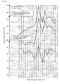
- noise of a compressor is wind noise generated by the rotation of an impeller of the compressor and is composed mainly of the frequency of a degree component of the number of blades.
- This noise for example, is characterized in that, as shown in Fig. 22 , a basic frequency of 1650 (3300) Hz calculated by number of blades ⁇ number of rotations ⁇ 60 (second) and frequency components close to an overtone component of this basic frequency are very high compared to other frequency components.
- a basic frequency of 1650 (3300) Hz is calculated on the assumption that the number of blades is 11 (22) and the number of rotations is 9000 rpm.
- a silencer for a supercharger is required to obtain a high amount of silencing in order to reduce noise of this supercharger.
- a supercharger is desired to be highly efficient (in other words, a high discharge pressure).
- manufacturers of a supercharger in the world compete with each other. In general, it is said that when a pressure loss of an intake side is reduced by 10 mmAq, efficiency of a supercharger is improved by 1 %.
- a lower pressure loss of a silencer for a supercharger mounted on an intake side is an important factor for improving efficiency of a supercharger.
- a silencer for a supercharger is required not only to obtain a high amount of silencing, but to have a low pressure loss.
- the representative structure of a large silencer for a supercharger is divided into three structures, that is, a cylindrical outer circumference suction silencer, a cylindrical front suction silencer and a square front suction silencer depending on air suction flow.
- a cylindrical outer circumference suction silencer is mounted on an engine while it is directly connected to a supercharger.
- a silencing element for silencing this noise is configured by arranging a plurality of Z-shaped plate-like sound-absorbing splitters radially in a circumferential direction at a regular pitch between the inside diameter and the outside diameter of the silencer.
- This cylindrical outer circumference suction silencer sends a sound wave with a higher frequency than a basic frequency to a bend portion of a sound-absorbing splitter to silence noise and also ensures an air flow path from the circumference to the center between each sound-absorbing splitter to reduce a pressure loss.
- a cylindrical front suction silencer is configured so as to suction air from the front side (front) of the silencer backward to an axial direction.
- noise of a supercharger is emitted against this air flow from the back of a silencer forward in an axial direction, specifically to the front side (front).
- a silencing element for silencing this noise is configured by arranging concentrically a plurality of cylindrical sound-absorbing cylinders with the center in an axial direction curved in a radial direction.
- This cylindrical front suction silencer sends a sound wave to a curved part of a sound-absorbing cylinder to obtain a large amount of silencing and secures an air flow path in an axial direction axially between each sound-absorbing cylinder to reduce a pressure loss.
- a square front suction silencer like a cylindrical front suction silencer, is configured so as to suction air from the front side of a silencer backward to an axial direction.
- noise of a supercharger is emitted against this air suction flow from the back of a silencer forward in an axial direction.
- a silencing element for silencing this noise is configured by arranging a plurality of plate-like sound-absorbing boards at a regular pitch in a direction perpendicular to an axial direction.
- This square front suction silencer obtain a prescribed amount of silencing by extending the length of a silencing element in an axial direction depending on a required amount of silencing and also secures an air flow path in an axial direction between each sound-absorbing board to reduce a pressure loss.
- Non-Patent Document http: //www.alpt.co.jp/products/s_charger.html
- a cylindrical outer circumference suction silencer is excellent in mass productivity because the size of a plurality of sound-absorbing splitters can be the same.
- the cost of a cylindrical outer circumference suction silencer is the lowest of the three types of silencers.
- the outside diameter (do) must be almost the same as the outside diameter of a supercharger and the inside diameter (di) is unambiguously determined by the diameter of the interface of a supercharger. Therefore, a silencing element has to be arranged in this limited space. Since the length of the path of a silencing element is limited to ⁇ (do-di) ⁇ 2 ⁇ , there is a limit to increasing an amount of silencing.
- a cylindrical front suction silencer was originally developed to eliminate the weak point of a cylindrical outer circumference suction silencer and is better in securing an amount of silencing than a cylindrical outer circumference suction silencer. Specifically, a cylindrical front suction silencer can easily secure a required amount of silencing by adjusting the length in an axial direction of a sound-absorbing cylinder.
- a square front suction silencer has been developed to eliminate disadvantages of the two types of silencers mentioned above, and obtains a larger amount of silencing than a cylindrical outer circumference suction silencer and is more cost-effective than a cylindrical front suction silencer.
- the inventors take into consideration the characteristics of the three types of silencers mentioned above and focus attention on the lowest cost of a cylindrical outer circumference suction silencer. While taking advantage of the low cost of a cylindrical outer circumference suction silencer, to overcome difficulty in increasing an amount of silencing of which a cylindrical outer circumference suction silencer has a disadvantage, the inventors aim to provide a silencer for a supercharger having optimal cost reduction and go improvement in an amount of silencing, and a supercharger using this silencer.
- the silencer for a supercharger of the present invention is characterized in that a silencer for a supercharger is attached to an air inlet through which air is suctioned by a compressor provided in a supercharger and silences noise generated by the compressor at the time of suctioning air, wherein a plurality of plate-like sound-absorbing splitters are arranged along the inner circumference of the air inlet in a circumferential direction having a prescribed central axis as the center with each gap provided in a radial direction, to suction the air with each of the gaps as a flow path from outwardly to inwardly in the radial direction and to absorb the noise emitted from inwardly to outwardly in the radial direction against the air flow in the plurality of sound-absorbing splitters, wherein any of the sound-absorbing splitters and another sound-absorbing splitter adjacent thereto in the circumferential direction are formed in a shape along a site having the same distance interval from an origin in each of a plurality of in
- a flow path width between adjacent sound-absorbing splitters is kept constant without changing the thickness of a sound-absorbing splitter.
- a flow path width is adjusted to be suitable for this wavelength, the noise of the basic frequency of 1650 Hz and the overtone of the basic frequency of 3300 Hz is silenced efficiently.
- the silencer for a supercharger of the present invention is also characterized in that any of the sound-absorbing splitter and another sound-absorbing splitter adjacent thereto in the circumferential direction is formed in a shape on the basis of the pair of involute curves, as the plurality of involute curves, applicable to any of the plurality of patterns of the pair of involute curves having the same radius and/or having different intervals from the different origins and by allocating all of the plurality of patterns to a shape of any pair of sound-absorbing splitters adjacent to each other of the plurality of sound-absorbing splitters, a flow path having the prescribed flow path width corresponding to each of the plurality of patterns is selectively arranged in accordance with a position in the circumferential direction.
- the silencer for a supercharger of the present invention is further characterized in that any of the sound-absorbing splitters and another sound-absorbing splitter adjacent thereto in the circumferential direction are each formed into a shape along a compound curve portion linking some portions of a plurality of involute curves in the normal or reverse involute direction on the basis of a fixed circle having the same center in a normal direction or in a reverse direction.
- a sound-absorbing splitter can absorb noise efficiently to further increase an amount of silencing.
- the silencer for a supercharger of the present invention is also characterized in that the constant value is 1/2 of the wavelength of the noise to be silenced.
- a flow path width can be adjusted to an optimal value to the wavelength of the noise to be silenced to achieve one of the most effective silencing.
- the silencer for a supercharger of the present invention is also characterized in that the array pitch of the sound-absorbing splitter is set at a value suitable for the wavelength of the noise to be silenced.
- the silencer for a supercharger of the present invention is also characterized in that the dimension of the array pitch is the same as the wavelength of the noise to be silenced.
- an array pitch of a sound-absorbing splitter can be adjusted to the optimal value for the wavelength of the noise to be silenced to achieve one of the most effective silencing.
- the silencer for a supercharger of the present invention is also characterized in that the wavelength of the noise to be silenced corresponds to a basic frequency of the noise.
- the supercharger of the present invention is characterized in that the supercharger has a silencer for a supercharger, wherein a plurality of sound-absorbing splitters are arranged along the inner circumference of an air inlet radially with each interval set in a circumferential direction having a prescribed central axis as the center, having an origin having as the basis therefor a fixed circle having the same center as the central axis, and formed along an involute curve, and wherein a flow path width formed by sound-absorbing splitters adjacent in the circumferential direction is set at a prescribed width suitable for the wavelength of the noise to be silenced.
- a silencer for a supercharger having optimal cost reduction and good improvement in an amount of silencing and a supercharger using this silencer can be achieved.
- the silencer of a supercharger of the present invention in a first embodiment is explained by referring to Figs. 1 to 8 .
- a silencer for a supercharger 1 in this embodiment is mounted at an air inlet 4 through which suction of air is performed by a compressor 3 provided in the a supercharger and is configured so as to silence noise generated by the compressor 3 at the time of the suction of air.
- the noise silenced by the silencer for a supercharger 1 does not prevent inclusion of noise by a turbine not illustrated.
- the silencer for a supercharger 1 in this embodiment is a cylindrical outer circumference suction silencer mentioned above.
- the silencer for a supercharger 1 has two outer discs 2A and 2B arranged in parallel with each other with an interval in a horizontal direction in Fig. 1 .
- Each of these outer discs 2A and 2B has the same outside diameter. It is desirable that these outer discs 2A and 2B are formed by strong steel to insulate noise by the compressor 3.
- a circular hole 5 with a relatively large diameter is drilled concentrically.
- a cylindrical body 7 is extending at an end of an inner circumference of the outer disc 2B to the side of an air inlet 4 and a flange 8 extending radially outwardly is provided around a tip of this cylindrical body 7. From this flange 8, to the cylindrical body 7 and the outer disc 2B, multiple radiate stiffeners 10, 10 ⁇ are fixed and as a result, the outer disc 2B and the cylindrical body 7 are strongly integrated.
- a wire netting 11 and a filter 12 removing dust from air are wound starting from an inside of a radial direction between outer circumferential edges of both the outer discs 2A and 2B mentioned above.
- a silencing element 15 having two inner discs 14A and 14B is arranged so that the silencing element faces each of the outer discs 2A and 2B from inside.
- Circular holes 16A and 16B having the same inside diameter and the same center as the circular hole 5 of the outer disc 2B are drilled on each of the inner discs 14A and 14B.
- These sound absorbing bodies 17A and 17B may house a net-like or non-woven fabric-like sound absorbing material not illustrated made of material including glass wool inside the surface covered by a punching plate made of metal including aluminum.
- the sound absorbing body 17B arranged between the discs 2B and 14B on the right in Fig. 1 is extending to the end of the inner circumference of both the discs 2B and 14B, forming a disc-shape as a whole.
- a sound absorbing body 17A arranged between the discs 2A and 14A on the left in Fig. 1 is extending beyond the end of the inner circumference of the inner disc 14A to the center side of the outer disc 2A.
- a portion 17Aa extending to the center side of the outer disc 2A of the sound absorbing body 17A constitutes a tapered almost cone-shape portion 17Aa projecting to the side of the circular hole 5.
- the tip of this corn-shaped portion 17Aa reaches into the circular hole 5.
- the circumference surface of this corn-shaped portion 17Aa is formed in a corn-shape to introduce air suctioned into the silencer for a supercharger 1 with a small pressure loss to the side of the air inlet 4.
- the corn-shaped portion 17Aa is responsible for silencing noise by the compressor 3 coming from the side of the air inlet 4.
- the silencing element 15 has a plurality of plate-like sound-absorbing splitters 20, 20 ⁇ having a sound-absorbing function fixed between the two inner discs 14A and 14B mentioned above.
- Each sound-absorbing splitter 20 is arranged along the inner circumference of the air inlet 4 radially with each interval having a constant dimension provided in a circumferential direction having a prescribed central axis (CA) as the center.
- CA central axis
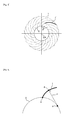
- any of the sound-absorbing splitters 20 and another sound-absorbing splitters 20 adjacent thereto at both of the circumferential directions are formed in a bent plate-like shape along a site I' having the same distance interval from an origin of each of a plurality of involute curves l having different origins (in other words, starting points) a having as the basis thereof a fixed circle C having the same center and the same radius as a central axis (CA).
- a site I' having the same distance interval from an origin of each of a plurality of involute curves l having different origins (in other words, starting points) a having as the basis thereof a fixed circle C having the same center and the same radius as a central axis (CA).
- CA central axis
- the flow path width w that is a dimension in the normal line of the involute curve I in the flow path 19 between each pair of any of the sound-absorbing splitters 20, 20 composed of any sound-absorbing splitters 20 and another sound-absorbing splitters 20 adjacent thereto is set at 1/2 of a wavelength as a prescribed constant value suitable for the wavelength of the noise to be silenced.
- the wavelength ⁇ of the noise to be silenced is desired to be a wavelength c/F (c represents sound speed) corresponding to a basic frequency F with the highest noise level.
- the involute curve I is a plane curve, the normal line n thereof being constantly tangent to one fixed circle C, and is also called the involute of circle or anti-clothoid.
- This involute curve I is obtained as a locus that the tip of a tread draws when the thread wound around the fixed circle C is undone while the thread is being pulled straight without rotating the fixed circle C.
- the center of curvature of any point P on the involute curve I is a tangent point b of the normal line n and the fixed circle C at this point P, the distance between this P and b is the radius of curvature of the involute curve I at the point P.
- a radius of curvature and a center of curvature vary depending on a point P.
- each sound-absorbing splitter 20 is formed along this involute curve I, a constant flow path width w mentioned above is secured without changing the thickness of each sound-absorbing splitter 20.
- this flow path width w into a dimension suitable in terms of silencing for the wavelength of the frequency to be silenced, the energy of the sound of the frequency is effectively absorbed into a sound-absorbing splitter 20 and a larger amount of silencing is obtained.
- a basic frequency is 1650 Hz
- a wave wavelength thereof is sound speed 340 (m/s)
- frequency 1650 (Hz) 20.6 cm.
- the overtone of the basic frequency is 3300 Hz
- a wavelength thereof is sound speed 340 (m/s)
- ⁇ frequency 3300 (Hz) 10.3 cm.
- a flow path width w is arranged to be suitable for this wavelength, the basic frequency of 1650 Hz and the overtone of 3300 Hz of this basic frequency are effectively silenced.
- an array pitch p (see Fig. 2 ) is set at the same dimension as a wavelength as a value suitable for the wavelength of the noise to be silenced (for example, the wavelength corresponding to a basic frequency).
- An array pitch p is equivalent to a value calculated by adding to the thickness t of a sound-absorbing splitter 20 to a flow path width w.
- a core plate 22 is put at the center portion of a glass wool board 21 made of glass wool fiber processed into an arch shape matched to an involute curve and the surface of a board 21 is covered by an aluminum punching plate 23 in order to prevent the fiber from dispersing by air flow.
- a sound-absorbing splitter 20 in Fig. 6 tips in a longitudinal direction are protected by aluminum extruded material 24 formed into a shape to reduce flow resistance.
- a polyester board 26 made of heat-welded soft plate-like polyester fiber is firmly bonded with adhesive on both sides of a core plate 22 like the core plate in Fig. 6 . Tips in a longitudinal direction of this sound-absorbing splitter 20 in Fig. 7 are also processed into a shape to reduce flow resistance as in Fig. 6 .
- the sound-absorbing splitter 20 in Fig. 7 is heat-welded polyester fiber, no dispersion by air flow occurs as in the glass wool board 21, protection of the surface is not necessary.
- a concrete structure of the sound-absorbing splitter 20 is not limited to examples shown in Figs. 6 and 7 .
- air suctioned by the compressor 3 is mostly dispersed into each flow path 19 between each pair of adjacent sound-absorbing splitters 20, 20 of the silencing element 15 when the air is flowed from outwardly (outer circumferential side) in the radial direction of the silencer for a supercharger 1. Then, the air dispersed into each flow path 19 is flowed in each flow path 19 inwardly in the radial direction. Then, since the sound-absorbing splitter 20 that defines the shape of each flow path 19 is formed into a smooth shape along an involute curve, sudden change in direction of air in each flow path 19 is reduced to decreace a pressure loss.
- each flow path 19 is released from the end of the inner circumference of each sound-absorbing splitter 20 into the center in the silencer for a supercharger 1 outside each flow path 19 and then is suctioned into the side of the air inlet 4, and further is compressed by the compressor 3 and is supplied efficiently to a cylinder of an engine not illustrated.
- noise generated by the compressor 3 when air is suctioned is, as shown with a dashed arrow in Fig. 1 , flows into the center of the silencer for a supercharger 1 from the side of the air inlet 4 against air flow and is emitted from inwardly to outwardly in a radial direction.
- each sound-absorbing splitter 20 is formed into a shape along an involute curve, the flow path width w of each flow path 19 is set at a constant value ⁇ /2 suitable for the wavelength ⁇ of the noise to be silenced, without having to change the thickness of each sound-absorbing splitter 20, noise corresponding to the wavelength ⁇ is silenced effectively with a simple structure (see "Machine Noise Handbook (Sangyo Tosho)" P. 506, 1. 10).
- the pitch p of each sound-absorbing splitter 20 is set at a constant value ⁇ suitable for the wavelength ⁇ of the noise to be silenced, noise corresponding to the wavelength ⁇ is silenced more effectively.
- the wavelength ⁇ is a wavelength corresponding to a basic frequency, an amount of silencing can be increased further.
- a flow path width 19 between a pair of adjacent sound-absorbing splitters 20, 20 is kept constant easily, by adjusting this flow path width 19 to the wavelength of the noise to be silenced, an amount of silencing is increased effectively while a space for mounting a sound-absorbing splitter 20 is limited in the radial direction.
- a supercharger using the silencer for a supercharger 1 of this embodiment is made smaller and can achieve a high pressure ratio and high efficiency in quiet operation despite a high rotation speed.
- the radius of a fixed circle C defining an involute curve I may be changed appropriately according to a desired amount of silencing.
- a desired amount of silencing For example, in a structure shown in Fig. 3 , when only the radius of a fixed circle C is changed to a smaller radius, the curvature of the involute curve I becomes larger and a distance interval w' of a pair of adjacent involute curves I, I becomes smaller and also the length of a site I' at a constant distance from an origin a becomes longer. Then, since when this shape is reflected in a sound-absorbing splitter 20, a flow path 19 with a smaller flow path width w, in other words, with a smaller cross-section area and with a longer flow path, is obtained, an amount of silencing is further increased.
- the number of sound-absorbing splitters 20 may be changed appropriately according to a desired amount of silencing. For example, in the structure shown in Fig. 2 , when only the number of the sound-absorbing splitters 20 is increased, an amount of silencing is increased because a flow path width w becomes smaller.
- Fig. 8 shows an involute curve group that defines the shape of each sound-absorbing splitter 20 in this case.
- a second embodiment of a silencer for a supercharge 1 is illustrated by referring to Figs. 9 and 10 .
- a flow path width w of a flow path 19 between a pair of adjacent sound-absorbing splitters 20, 20 is a constant value in the flow path 19.
- each flow path width w of the flow path 19 is not set at an equal value.
- any sound-absorbing splitter 20 and another sound-absorbing splitter 20 adjacent thereto are formed in a shape, as shown in Fig. 9 , on the basis of a pair of involute curves corresponding to any of a plurality of patterns of a pair of involute curves I (ri, di) (i: one to multiple patterns) having a radius (the same radius) ri of a fixed circle C and having different degree intervals di between each different origin a.
- Fig. 9 For convenient sake, three patterns are indicated in Fig. 9 , there is no need to limit to these patterns.
- either the radius ri of a fixed circle C or the degree interval di between each different origins a may be the same.
- all of the plurality of patterns are allocated to a shape of any of the sound-absorbing splitters 20 adjacent to each other of a plurality of sound-absorbing splitters 20, so that, as shown in Fig. 10 , flow paths 19 having a constant flow path width w1, w2, w3 different from earth other corresponding to each of a plurality of patterns are arranged selectively according to a position in a circumferential direction.
- each interval between flow path w1, w2, and w3 may be made as small as possible.
- a wavelength of suitable noise is changed according to a flow path 19, and by responding flexibly to the change of a wavelength of the noise to be silenced due to change in a rotation speed of the compressor 3 (for example, change in a wavelength corresponding to a basic frequency along with change in the basic frequency), a high amount of silencing is stably maintained.
- a silencer for a supercharger 1 in a third embodiment is explained by referring to Figs. 11 to 21 .
- any sound-absorbing splitter 20 and another sound-absorbing splitter 20 adjacent thereto are each formed in a shape along a compound curve portion wherein a portion of a plurality of involute curves in a normal direction (the same direction) or in a reverse direction (opposite direction) having as the basis thereof a fixed circle having the same center are connected.
- a basic structure wherein sound-absorbing splitters 20 adjacent to each other are formed in a shape along a site having the same distance interval from an origin in each of a plurality of involute curves having the same center and having the same radius but having different origins is the same as in each embodiment mentioned above.
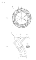
- sound-absorbing splitters 20 and flow paths 19 are formed in a dogleg shape and as shown in an overall view in Fig. 12 (a) and an enlarged view of a main part in 12 (b), sound-absorbing splitters 20 and flow paths 19 are formed almost in an S-shaped form.
- the structure in Fig. 11 is, as shown in Fig. 13 , based on curve portions L1 wherein portions of two involute curves 11, 12 in opposite involute directions (direction of undoing a string) as the basis thereof fixed circles C1, C2 having the same center as a compound curve portion is connected.
- fixed circles C1, C2 are the same (in other words, having the same center and the same radius or involute curves I1, I2 having the same curvature), and each interval between origins of two involute curves I1, I2 may be the same.
- each radius of fixed circles C1, C2 may be different.
- Fig. 12 the structure in Fig. 12 is, as shown in Figs. 14 and 15 , based on a curve portion L2 wherein portions of three involute curves I1, I2, I3 in a normal or reverse involute direction having as the basis thereof fixed circles C 1, C 2, C 3 (C 2 ⁇ C 1 ⁇ C 3) having the same center but having different radius as a compound curve portion are connected.
- a sound-absorbing splitter 20 is based on a linear shape articulated to an inner end of an involute curve I3 parallel in a radial direction.
- Fig. 15 shows each of the involute curves I1, I2, I3 that are the basis of the compound curve portion in Fig. 14 .
- di is a diameter, as an inside diameter, of a sound-absorbing splitter 20
- r1, r2, r3 in 15 is a radius of fixed circles (C1, C 2, C 3) corresponding to each involute curve I (I1, I2, I3)
- do is a diameter, as an outside diameter, of a sound-absorbing splitter 20.
- the involute curves I2 and I3 have the same involute direction while the involute curve I2 (or I3) and I1 have opposite involute directions.
- the sound-absorbing splitter 20 absorbs noise efficiently and an amount of silencing is further increased.
- the silencer for a supercharger (cylindrical outer circumference suction silencer) in the comparative example has a silencing element 15' having a Z-shaped sound-absorbing splitter 20' arranged radially between the outside diameter and the inside diameter of the silencer.
- the process air volume of a silencing element 15' is set at 44 m 3 /m and, as shown in Fig. 16 (a) , the outside diameter is set at 2100 mm to match an external form of a supercharger and also the inside diameter is set at 1300 mm to match the diameter of an inlet of the supercharger.
- an amount of silencing needs to be 45 dB (A) or more for the entire silencer for a supercharger. Of this amount of silencing, noise from the silencing element 15' needs to be reduced by 29 dB (A) or more.
- the silencer for a supercharger in the comparative example has a further specific structure shown below.
- the silencer for a supercharger in the comparative example has 48 sound-absorbing splitters 20' arranged at an equal interval in a circumferential direction.
- the sound-absorbing splitter 20' is formed in a "dogleg" shape from an outside diameter to an inside diameter, and further the tip (inner end) thereof is formed almost in a Z-shape bent to be parallel to a radial direction toward the center.
- the thickness t of a sound-absorbing splitter 20' is set at 25 mm
- the flow path width is set at 75 mm
- the array pitch p of a sound-absorbing splitter 20' is set at 100 mm
- the flow path (gross length) l is set at 450 mm.
- the frequency to be silenced best is calculated from the relationship between wavelength ⁇ and a flow path width w as shown below.
- a frequency to be silenced best is calculated from the relationship between a wavelength ⁇ and an array pitch p as shown below.
- the actual measured value of a silencing characteristic of an silencing element15' alone is as shown in Fig. 18
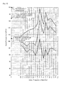
- the actual measured value of a noise characteristic (A characteristic) after passing through a silencer for a supercharger having a built-in silencing element 15' is as shown in the bottom line graph in Fig. 17 .
- the middle line graph shown in Fig. 17 is the actual measured value of noise characteristic (A characteristic) after passing through a silencer for a supercharger not having a built-in silencing element 15.'
- an amount of silencing peaks at 3150 Hz close to a designed value of 3400 Hz (the center of high frequency domain is 3300 Hz) and the graph has a slightly sharp chevron characteristic with an amount of silencing of 30 dB or more in a prescribed frequency range around 3150 Hz.
- noise after correction of A characteristic corresponding to the bottom graph in Fig. 17 is 104 dB (A), equal to or less than targeted 105 dB (A).
- a noise level at a basic frequency of 1650 Hz is higher by 15 dB or more than at frequencies (1250 Hz, 2000 Hz) around the basic frequency. This shows an unequal amount of silencing at the basic frequency and at overtone.
- This noise characteristic does not show a balanced reduction of a noise level at the basic frequency of 1650 Hz and an overtone thereof of 3300 Hz.
- a silencer for a supercharger 1 in the Example as shown in an overall view in Fig. 19 (a) and an enlarged view of a main part in Fig. 19 (b) , is provided, between an outside diameter and an inside diameter of the silencer, with a silencing element 15 having nearly S-shaped sound-absorbing splitters 20 arranged concentrically, radially along a compound curve portion consisting of three involute curves.
- the process air volume of the silencing element 15, as in the comparative example is set at 44 m 3 /m, and, as shown in Fig. 19 (a) , an outside diameter is set at 2100 mm to match the external form of the supercharger. On the other hand, as shown in Fig. 19 (a) , the inside diameter is set at 1100 mm slightly smaller than the inside diameter in the comparative example.
- noise of 150 dB (A) generated inside the supercharger after acoustic feeling correction (A characteristic) corresponding to the top graph in Fig. 20 (the same graph of the bottom graph in Fig. 17 ) is aimed to be reduced to less than 100 dB (A) at the surrounding of the supercharger.
- an amount of silencing of 50 dB (A) or more is required for the entire silencer for a supercharger, and the noise from the silencing element 15 needs to be reduced by 34 dB (A) or more.
- an amount of silencing of the silencing element 15 (required amount of silencing is 34 dB (A)) in the Example needs to be increased by 5 dB (A) compared to an amount of silencing of the silencing element 15' (required amount of silencing 29 dB (A)) in the comparative example.
- a peak frequency of silencing is aimed to be 2475 Hz (intermediate frequency between the basic frequency of 1650 Hz and the overtone of 3300 Hz) lower in the comparative example (3400 Hz).
- the silencer for a supercharger in the Example is provided with a further specific structure.
- the silencer for a supercharger in the Example has 24 sound-absorbing splitters 20 using an involute curve arranged at a constant interval in a circumferential direction.
- the thickness t of the sound-absorbing splitter 20 is set at 40 mm
- the flow path width w is set at 100 mm
- the array pitch p is set at 140 m
- the flow path l is set at 650 mm.
- the frequency to be silenced best is calculated from the relationship between wavelength ⁇ and a flow path width w as shown below.
- a frequency to be silenced best is calculated from the relationship between a wavelength ⁇ and an array pitch p as shown below.
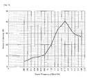
- the actual measured value of a silencing characteristic of an silencing element 15 alone is as shown in Fig. 21
- the actual measured value of a noise characteristic (A characteristic) after passing through a silencer for a supercharger having a built-in silencing element 15 is as shown in the bottom line graph in Fig. 20
- the middle line graph shown in Fig. 20 is the actual measured value of noise characteristic (A characteristic) after passing through a silencer for a supercharger 1 not having a built-in silencing element 15 and this graph is the same as the middle graph in Fig. 17 .
- the silencing characteristic of the silencing element 15 alone is a slightly shallow chevron characteristic in which an amount of silencing peaks at 2500 Hz close to a designed value of a peak frequency of 2475 Hz (2429 Hz, a calculated value by a flow path width w and an array pitch p) and an amount of silencing is 35 dB or more in a prescribed frequency range around 2500 Hz.
- the frequency range showing an amount of silencing of 35 dB or more includes a basic frequency of a supercharger (noise) of 1650 Hz and an overtone of 3300 Hz.
- noise after correction of A characteristic corresponding to the bottom graph in 20 is 98 dB (A), equal to or less than targeted 100 dB (A).
- a peak frequency of silencing at the midpoint between the basic frequency (1650 Hz) and the overtone (3300 Hz) an amount of silencing at 1600 Hz, close to the basic frequency, is 39 dB and an amount of silencing at 3150 Hz, close to the overtone, is 42 dB and almost the same amount of silencing is obtained.
- noise at 1600 Hz, close to the basic frequency is 103 dB and noise at 3150 Hz, close to the overtone, is 88 dB and there is a difference of as much as 15 dB therebetween.
- noise close to the basic frequency (1600 Hz) of 103 dB is slightly different by as little as 1 dB from noise of 104 dB (A) after correction of A characteristic, noise at the basic frequency has a large influence on the entire noise.
- noise at 1600 Hz, close to the basic frequency is 92 dB and noise at 3150 Hz, close to the overtone, is 87 dB and the difference therebetween is reduced to 5 dB.
- noise close to the basic frequency (1600 Hz) of 92 dB is different by 6 dB from noise after correction of A characteristic of 98 dB (A)
- the influence of noise at the basic frequency on the entire noise is mitigated compared to the comparative example.
- the silencer for a supercharger 1 in the Example unlike the silence for a supercharger in the comparative example, noise at both the basic frequency of 1650 Hz and the overtone of 3300 Hz is silenced to almost the same balanced amount.
- the number of sound-absorbing splitters 20 in the silencing element 15 can be reduced (halved) from 48 (comparative example) to 24 (Example), a significant cost reduction is possible even allowing for a thicker (40 mm) sound-absorbing splitter 20 than the sound-absorbing splitter in the comparative example (25 mm) and a longer flow path 1 (650 mm) than the flow path in the comparative example (450 mm).
- the present invention is not limited to the three embodiments mentioned above and a variety of modification can be made as necessary.
- the second embodiment and the third embodiment may be combined.
Landscapes
- Engineering & Computer Science (AREA)
- Mechanical Engineering (AREA)
- General Engineering & Computer Science (AREA)
- Chemical & Material Sciences (AREA)
- Combustion & Propulsion (AREA)
- Chemical Kinetics & Catalysis (AREA)
- General Chemical & Material Sciences (AREA)
- Supercharger (AREA)
- Applications Or Details Of Rotary Compressors (AREA)
Applications Claiming Priority (2)
| Application Number | Priority Date | Filing Date | Title |
|---|---|---|---|
| JP2012272308A JP6152612B2 (ja) | 2012-12-13 | 2012-12-13 | 過給機用サイレンサおよびこのサイレンサを使用した過給機 |
| PCT/JP2013/083425 WO2014092174A1 (ja) | 2012-12-13 | 2013-12-13 | 過給機用サイレンサおよびこのサイレンサを使用した過給機 |
Publications (2)
| Publication Number | Publication Date |
|---|---|
| EP2933470A1 true EP2933470A1 (de) | 2015-10-21 |
| EP2933470A4 EP2933470A4 (de) | 2016-05-25 |
Family
ID=50934455
Family Applications (1)
| Application Number | Title | Priority Date | Filing Date |
|---|---|---|---|
| EP13861818.6A Withdrawn EP2933470A4 (de) | 2012-12-13 | 2013-12-13 | Schalldämpfer für auflader und auflader mit diesem schalldämpfer |
Country Status (5)
| Country | Link |
|---|---|
| EP (1) | EP2933470A4 (de) |
| JP (1) | JP6152612B2 (de) |
| KR (1) | KR20150065894A (de) |
| CN (1) | CN104870800B (de) |
| WO (1) | WO2014092174A1 (de) |
Cited By (1)
| Publication number | Priority date | Publication date | Assignee | Title |
|---|---|---|---|---|
| DE102018100466A1 (de) * | 2018-01-10 | 2019-07-11 | Abb Turbo Systems Ag | Filterschalldämpfer für einen Abgasturbolader einer Brennkraftmaschine |
Families Citing this family (6)
| Publication number | Priority date | Publication date | Assignee | Title |
|---|---|---|---|---|
| JP6392103B2 (ja) * | 2014-12-09 | 2018-09-19 | 三菱重工業株式会社 | 吸音装置、遠心圧縮機、および過給機 |
| JP6200443B2 (ja) * | 2015-03-26 | 2017-09-20 | 三菱重工業株式会社 | 過給機用サイレンサ及び過給機 |
| DE102018100465A1 (de) * | 2018-01-10 | 2019-07-11 | Abb Turbo Systems Ag | Filterschalldämpfer für einen Abgasturbolader einer Brennkraftmaschine |
| DE102018102237A1 (de) * | 2018-02-01 | 2019-08-01 | Man Energy Solutions Se | Schalldämpfer und Verdichter |
| CN110159568A (zh) * | 2019-06-12 | 2019-08-23 | 珠海格力电器股份有限公司 | 导流装置及无叶风扇 |
| DE102020122027B4 (de) * | 2020-08-24 | 2023-05-04 | Mann+Hummel Gmbh | Schalldämpfer und Filtersystem |
Family Cites Families (10)
| Publication number | Priority date | Publication date | Assignee | Title |
|---|---|---|---|---|
| DE59004955D1 (de) * | 1989-12-22 | 1994-04-14 | Emitec Emissionstechnologie | Abgasleitung mit wendelförmig angeströmtem katalysator-trägerkörper. |
| JPH05195893A (ja) * | 1992-01-20 | 1993-08-03 | Toushiyou Eng Kk | 通路断面積変化型消音装置 |
| DE19514990B4 (de) * | 1995-04-24 | 2005-06-30 | Abb Turbo Systems Ag | Filterschalldämpfer |
| JP2876000B1 (ja) * | 1998-01-13 | 1999-03-31 | 三菱アルミニウム株式会社 | 過給機のサイレンサ |
| JP3425120B2 (ja) | 2000-06-21 | 2003-07-07 | アルパテック株式会社 | 過給機のサイレンサ |
| JP2004360547A (ja) | 2003-06-04 | 2004-12-24 | Arupatec Kk | 過給機用サイレンサ |
| JP4204437B2 (ja) * | 2003-10-09 | 2009-01-07 | 象印マホービン株式会社 | 空気清浄機 |
| JP2006194161A (ja) * | 2005-01-14 | 2006-07-27 | Mitsubishi Heavy Ind Ltd | 吸気サイレンサを備えた排気ターボ過給機 |
| SE528857C2 (sv) * | 2005-04-27 | 2007-02-27 | Scania Cv Ab | Anordning för dämpning av ljud i en ledning |
| GB2426555A (en) * | 2005-05-28 | 2006-11-29 | Siemens Ind Turbomachinery Ltd | Turbocharger air intake |
-
2012
- 2012-12-13 JP JP2012272308A patent/JP6152612B2/ja active Active
-
2013
- 2013-12-13 WO PCT/JP2013/083425 patent/WO2014092174A1/ja not_active Ceased
- 2013-12-13 EP EP13861818.6A patent/EP2933470A4/de not_active Withdrawn
- 2013-12-13 KR KR1020157012434A patent/KR20150065894A/ko not_active Ceased
- 2013-12-13 CN CN201380064749.6A patent/CN104870800B/zh not_active Expired - Fee Related
Cited By (2)
| Publication number | Priority date | Publication date | Assignee | Title |
|---|---|---|---|---|
| DE102018100466A1 (de) * | 2018-01-10 | 2019-07-11 | Abb Turbo Systems Ag | Filterschalldämpfer für einen Abgasturbolader einer Brennkraftmaschine |
| US11549471B2 (en) | 2018-01-10 | 2023-01-10 | Abb Schweiz Ag | Filter muffler for an exhaust gas turbocharger of an internal combustion engine |
Also Published As
| Publication number | Publication date |
|---|---|
| CN104870800A (zh) | 2015-08-26 |
| JP2014118832A (ja) | 2014-06-30 |
| WO2014092174A1 (ja) | 2014-06-19 |
| KR20150065894A (ko) | 2015-06-15 |
| CN104870800B (zh) | 2018-06-22 |
| JP6152612B2 (ja) | 2017-06-28 |
| EP2933470A4 (de) | 2016-05-25 |
Similar Documents
| Publication | Publication Date | Title |
|---|---|---|
| EP2933470A1 (de) | Schalldämpfer für auflader und auflader mit diesem schalldämpfer | |
| JP2781168B2 (ja) | フィルタマフラ | |
| JP2007298027A (ja) | フィルタマフラ | |
| CN1191427C (zh) | 用于废气涡轮增压器的压气机的消声器 | |
| JP5583287B2 (ja) | 過給機用サイレンサ | |
| JP6392103B2 (ja) | 吸音装置、遠心圧縮機、および過給機 | |
| KR101611776B1 (ko) | 배기 터빈 과급기 | |
| EP3071434A1 (de) | Hochfrequenz-schalldämpfer für ein luftansaugsystem | |
| CN106884684A (zh) | 具有隔音件的导叶分离器 | |
| US9714630B2 (en) | Noise baffle for a rotary machine and method of making same | |
| JPH11200969A (ja) | 過給機のサイレンサ | |
| WO2013021366A2 (en) | Centrifugal fan with an anti-vortex fin for reducing vibrations and noise levels | |
| JP6097186B2 (ja) | 過給機用サイレンサ | |
| JP2004360547A (ja) | 過給機用サイレンサ | |
| RU2411398C2 (ru) | Многосекционный глушитель шума | |
| JP7258893B2 (ja) | 内燃機関の排ガスターボチャージャのためのフィルタ消音器 | |
| CN113464331A (zh) | 一种组合式消音器 | |
| RU2372499C1 (ru) | Глушитель шума | |
| JP4384933B2 (ja) | 過給機用サイレンサ | |
| JPH05195893A (ja) | 通路断面積変化型消音装置 | |
| JP6154312B2 (ja) | ダクト及びこれを備えたガスタービン | |
| RU2291324C1 (ru) | Глушитель шума (варианты) | |
| RU2411397C2 (ru) | Глушитель многосекционный для выхлопных воздуховодов компрессоров | |
| JP2013174177A (ja) | 過給機用サイレンサ | |
| RU154809U1 (ru) | Устройство для снижения уровня шума газотурбинного двигателя |
Legal Events
| Date | Code | Title | Description |
|---|---|---|---|
| PUAI | Public reference made under article 153(3) epc to a published international application that has entered the european phase |
Free format text: ORIGINAL CODE: 0009012 |
|
| 17P | Request for examination filed |
Effective date: 20150710 |
|
| AK | Designated contracting states |
Kind code of ref document: A1 Designated state(s): AL AT BE BG CH CY CZ DE DK EE ES FI FR GB GR HR HU IE IS IT LI LT LU LV MC MK MT NL NO PL PT RO RS SE SI SK SM TR |
|
| AX | Request for extension of the european patent |
Extension state: BA ME |
|
| DAX | Request for extension of the european patent (deleted) | ||
| A4 | Supplementary search report drawn up and despatched |
Effective date: 20160421 |
|
| RIC1 | Information provided on ipc code assigned before grant |
Ipc: F02M 35/12 20060101AFI20160415BHEP Ipc: F02B 37/00 20060101ALI20160415BHEP |
|
| STAA | Information on the status of an ep patent application or granted ep patent |
Free format text: STATUS: THE APPLICATION HAS BEEN WITHDRAWN |
|
| 18W | Application withdrawn |
Effective date: 20160912 |