EP2933475B1 - Générateurs de vortex alignés avec des caractéristiques de bord de fuite sur une pale d'éolienne - Google Patents
Générateurs de vortex alignés avec des caractéristiques de bord de fuite sur une pale d'éolienne Download PDFInfo
- Publication number
- EP2933475B1 EP2933475B1 EP15163469.8A EP15163469A EP2933475B1 EP 2933475 B1 EP2933475 B1 EP 2933475B1 EP 15163469 A EP15163469 A EP 15163469A EP 2933475 B1 EP2933475 B1 EP 2933475B1
- Authority
- EP
- European Patent Office
- Prior art keywords
- vortex
- trailing edge
- blade
- wind turbine
- waveform
- Prior art date
- Legal status (The legal status is an assumption and is not a legal conclusion. Google has not performed a legal analysis and makes no representation as to the accuracy of the status listed.)
- Active
Links
Images



Classifications
-
- F—MECHANICAL ENGINEERING; LIGHTING; HEATING; WEAPONS; BLASTING
- F03—MACHINES OR ENGINES FOR LIQUIDS; WIND, SPRING, OR WEIGHT MOTORS; PRODUCING MECHANICAL POWER OR A REACTIVE PROPULSIVE THRUST, NOT OTHERWISE PROVIDED FOR
- F03D—WIND MOTORS
- F03D1/00—Wind motors with rotation axis substantially parallel to the air flow entering the rotor
- F03D1/06—Rotors
- F03D1/0608—Rotors characterised by their aerodynamic shape
- F03D1/0633—Rotors characterised by their aerodynamic shape of the blades
-
- F—MECHANICAL ENGINEERING; LIGHTING; HEATING; WEAPONS; BLASTING
- F03—MACHINES OR ENGINES FOR LIQUIDS; WIND, SPRING, OR WEIGHT MOTORS; PRODUCING MECHANICAL POWER OR A REACTIVE PROPULSIVE THRUST, NOT OTHERWISE PROVIDED FOR
- F03D—WIND MOTORS
- F03D1/00—Wind motors with rotation axis substantially parallel to the air flow entering the rotor
- F03D1/06—Rotors
- F03D1/065—Rotors characterised by their construction elements
- F03D1/0675—Rotors characterised by their construction elements of the blades
-
- F—MECHANICAL ENGINEERING; LIGHTING; HEATING; WEAPONS; BLASTING
- F05—INDEXING SCHEMES RELATING TO ENGINES OR PUMPS IN VARIOUS SUBCLASSES OF CLASSES F01-F04
- F05B—INDEXING SCHEME RELATING TO WIND, SPRING, WEIGHT, INERTIA OR LIKE MOTORS, TO MACHINES OR ENGINES FOR LIQUIDS COVERED BY SUBCLASSES F03B, F03D AND F03G
- F05B2240/00—Components
- F05B2240/10—Stators
- F05B2240/12—Fluid guiding means, e.g. vanes
- F05B2240/122—Vortex generators, turbulators, or the like, for mixing
-
- F—MECHANICAL ENGINEERING; LIGHTING; HEATING; WEAPONS; BLASTING
- F05—INDEXING SCHEMES RELATING TO ENGINES OR PUMPS IN VARIOUS SUBCLASSES OF CLASSES F01-F04
- F05B—INDEXING SCHEME RELATING TO WIND, SPRING, WEIGHT, INERTIA OR LIKE MOTORS, TO MACHINES OR ENGINES FOR LIQUIDS COVERED BY SUBCLASSES F03B, F03D AND F03G
- F05B2240/00—Components
- F05B2240/20—Rotors
- F05B2240/30—Characteristics of rotor blades, i.e. of any element transforming dynamic fluid energy to or from rotational energy and being attached to a rotor
- F05B2240/306—Surface measures
- F05B2240/3062—Vortex generators
-
- F—MECHANICAL ENGINEERING; LIGHTING; HEATING; WEAPONS; BLASTING
- F05—INDEXING SCHEMES RELATING TO ENGINES OR PUMPS IN VARIOUS SUBCLASSES OF CLASSES F01-F04
- F05B—INDEXING SCHEME RELATING TO WIND, SPRING, WEIGHT, INERTIA OR LIKE MOTORS, TO MACHINES OR ENGINES FOR LIQUIDS COVERED BY SUBCLASSES F03B, F03D AND F03G
- F05B2250/00—Geometry
- F05B2250/10—Geometry two-dimensional
- F05B2250/18—Geometry two-dimensional patterned
- F05B2250/181—Geometry two-dimensional patterned ridged
-
- F—MECHANICAL ENGINEERING; LIGHTING; HEATING; WEAPONS; BLASTING
- F05—INDEXING SCHEMES RELATING TO ENGINES OR PUMPS IN VARIOUS SUBCLASSES OF CLASSES F01-F04
- F05B—INDEXING SCHEME RELATING TO WIND, SPRING, WEIGHT, INERTIA OR LIKE MOTORS, TO MACHINES OR ENGINES FOR LIQUIDS COVERED BY SUBCLASSES F03B, F03D AND F03G
- F05B2250/00—Geometry
- F05B2250/10—Geometry two-dimensional
- F05B2250/18—Geometry two-dimensional patterned
- F05B2250/183—Geometry two-dimensional patterned zigzag
-
- F—MECHANICAL ENGINEERING; LIGHTING; HEATING; WEAPONS; BLASTING
- F05—INDEXING SCHEMES RELATING TO ENGINES OR PUMPS IN VARIOUS SUBCLASSES OF CLASSES F01-F04
- F05B—INDEXING SCHEME RELATING TO WIND, SPRING, WEIGHT, INERTIA OR LIKE MOTORS, TO MACHINES OR ENGINES FOR LIQUIDS COVERED BY SUBCLASSES F03B, F03D AND F03G
- F05B2260/00—Function
- F05B2260/96—Preventing, counteracting or reducing vibration or noise
-
- Y—GENERAL TAGGING OF NEW TECHNOLOGICAL DEVELOPMENTS; GENERAL TAGGING OF CROSS-SECTIONAL TECHNOLOGIES SPANNING OVER SEVERAL SECTIONS OF THE IPC; TECHNICAL SUBJECTS COVERED BY FORMER USPC CROSS-REFERENCE ART COLLECTIONS [XRACs] AND DIGESTS
- Y02—TECHNOLOGIES OR APPLICATIONS FOR MITIGATION OR ADAPTATION AGAINST CLIMATE CHANGE
- Y02E—REDUCTION OF GREENHOUSE GAS [GHG] EMISSIONS, RELATED TO ENERGY GENERATION, TRANSMISSION OR DISTRIBUTION
- Y02E10/00—Energy generation through renewable energy sources
- Y02E10/70—Wind energy
- Y02E10/72—Wind turbines with rotation axis in wind direction
Definitions
- the invention relates generally to the field of wind turbines, and more particularly to an apparatus for noise reduction and aerodynamic enhancement of an airfoil of a wind turbine blade.
- Trailing edge aerodynamic noise ( Matthew F. Barone, "Survey of Techniques for Reduction of Wind Turbine Blade Trailing Edge Noise", Sandia National Laboratories, SAND20011-5252, August 2011, page 8 ). Trailing edge noise can be reduced by trailing edge serrations, as illustrated in FIG. 5 herein, which reduce the abruptness of the acoustic impedance mismatch between the merging suction side and pressure side flows at the trailing edge.
- Vortex generators are mounted on the suction side of an airfoil to induce vortices that entrain kinetic energy from the bulk airflow into the boundary layer flow immediately against the suction side surface. Energizing of the boundary layer delays flow separation on the airfoil and allows higher angles of attack without stall, thus allowing a wider range of operating configurations and higher overall efficiency. However, vortex generators can add noise and drag in some conditions.
- An object of the invention is a wind turbine blade with reducing noise and drag.
- a wind turbine blade comprises a predetermined alignment of vortex generating features with trailing edge features relative to an airflow path.
- the trailing edge features comprise a sequence of alternating peaks and valleys forming a trailing edge comprising a waveform as viewed from behind the blade and the repeating vortex generating features comprise a spanwise sequence of vortex generators designed to produce respective downstream vortices on a suction side of the blade that cross the waveform at a common phase thereof.
- the repeating trailing edge features comprise serrations forming a trailing edge comprising a waveform as viewed from above the blade and the vortex generating features comprise a spanwise sequence of vortex generators on a suction side of the blade, wherein each of the vortex generators is aligned relative to the airflow path with a respective period of the waveform at a common phase thereof.
- the repeating trailing edge features comprise serrations forming a trailing edge comprising a waveform as viewed from above and the vortex generating features comprise a spanwise sequence of vortex generators on a suction side of the blade, wherein each of the vortex generators is designed to produce a downstream vortical flow that crosses the trailing edge at an angle of less than 30 degrees from parallel with the trailing edge.
- the vortex generators comprise a spanwise sequence of pairs of first and second vortex generators designed to produce respective first and second respectively counter-rotating vortices, the first vortex generators are aligned relative to the airflow path with respective periods of the waveform at a common first phase thereof, and the second vortex generators are aligned relative to the airflow path with the respective periods of the waveform at a common second phase thereof.
- the repeating trailing edge features comprise serrations forming a trailing edge comprising a waveform trailing edge as viewed from above
- the repeating vortex generating features comprise a spanwise sequence of alternately angled vortex generators on a suction side of the blade designed to produce a spanwise sequence of pairs of first and second respectively alternately counter-rotating vortices downstream thereof, each of the first vortices crosses a respective period of the waveform at a common first phase thereof and each of the second vortices crosses the respective period of the waveform at a common second phase thereof.
- the trailing edge features are formed by alternating ridges and troughs on a suction side of the blade oriented relative to the airflow path and ending in a trailing edge with respectively alternating peaks and valleys defining a waveform as viewed from behind the blade, wherein the vortex generating features comprise a spanwise series of vortex generators, each of which is aligned in the relative airflow path with a portion of a respective one of the troughs.
- the vortex generators are designed to create the vortices to extend in diameter to a height of the trough over at least 75% of a length of the trough.
- each vortex generator is sunken into the suction side of the blade, and is formed by a vortex generator suction side with a top edge flush with the suction side of the blade, the vortex generator having no pressure side surface.
- the vortex generator suction side is convex as seen in a plan view of the blade.
- the vortex generator suction side tapers to a point at an adjacent one of the ridges, the vortex generator having no trailing edge.
- the repeating trailing edge features comprise serrations forming a trailing edge comprising a waveform as viewed from above the blade and the vortex generating features comprise a first spanwise sequence of vortex generators on a suction side of the blade and a second spanwise sequence of vortex generators on a pressure side of the blade, wherein each of the vortex generators is aligned relative to the airflow path with a respective period of the waveform at a common phase thereof.
- each of the suction side and pressure side vortex generators is designed to produce a respective downstream vortical flow that crosses the trailing edge at an angle of less than 30 degrees from parallel therewith.
- a wind turbine blade comprises a trailing edge with a waveform profile and a first spanwise series of vortex generators on a suction side of the blade, wherein each vortex generator of the first spanwise series is aligned chordwise with a common first phase of the waveform profile.
- the wind turbine profile comprises a second spanwise series of vortex generators, wherein each vortex generator of the second spanwise series is aligned chordwise with a common second phase of the waveform profile.
- the first and second series of vortex generators form a spanwise series of pairs, each of which comprises a vortex generator of the first series and a vortex generator of the second series, wherein each pair generates a respective pair of counter-rotating vortical flows, and each of the vortical flows crosses the trailing edge at an angle of less than 20 degrees.
- the waveform profile of the trailing edge is formed by a series of chordwise suction side troughs and an opposed nested series of chordwise pressure side ridges.
- the wind turbine blade comprises a plurality of first and second pressure side vortex generators on a pressure side of the blade, each first pressure side vortex generator aligned chordwise with the common first phase of the waveform profile, each second pressure side vortex generator aligned chordwise with the common second phase of the waveform profile, and each pressure side vortex generator designed to create a vortical flow that crosses the trailing edge at an angle of less than 20 degrees.
- each trough comprises a front end comprising a V-shaped drop-off from the suction side of the blade, sides of the V-shaped drop-offs forming respective pairs of vortex generators generating respective pairs of counter-rotating vortical flows within the respective troughs.
- a wind turbine blade comprises a plurality of drop-offs from a suction side surface of the blade functional in an airflow over the blade as vortex generators operable to generate respective vortices that each cross a waveform trailing edge of the blade at an angle of less than 30 degrees from parallel to the trailing edge.
- FIG 1 shows a prior art wind turbine blade 20 with a suction side aerodynamic surface 22 on which is mounted a spanwise row of paired vortex generators 26, 28 that create respectively counter-rotating vortices 27, 29 in the relative airflow 24. These vortices entrain kinetic energy from the relative airflow outside the boundary layer into the boundary layer, which delays or prevents flow separation from the aerodynamic surface 22.
- FIG 2 shows a vortex generator (VG) 28, which is a small airfoil extending from the larger aerodynamic surface 22 of the wind turbine blade 20.
- the VG has a pressure side 30 (hidden), suction side 32, leading edge 34, trailing edge 36, a root portion 38 attached to the larger aerodynamic surface, and a distal portion or tip 40.
- Such foils are commonly triangular or delta-shaped plates as shown, with a leading edge sweep angle ⁇ , such as 50-80 degrees.
- FIG 3 is a top view of a pair of diverging vortex generators 26, 28, separated by a distance called a pitch P.
- Each VG is a foil with a length L and an angle of incidence ⁇ relative to the relative airflow 24.
- An incidence angle ⁇ such as 10-40 degrees creates a pressure difference between the pressure and suction sides of the VG.
- the combination of high incidence angle ⁇ and high sweep angle ⁇ ( FIG 2 ) promotes flow from the pressure side 30 to the suction side 32 of the VG. As this local flow 40 wraps around the VG leading edge 34, it rolls into a vortex 27.
- FIG 4 is a sectional view of the VG 28 of FIG 3 taken along line 4-4, showing a vortex 29 that is not illustrated in FIG. 3 .
- FIG 5 is a perspective view of a wind turbine blade airfoil 20 with a serrated trailing edge 42.
- the serrations reduce trailing edge noise in some conditions.
- FIG 6 is a plan view of a spanwise sequence of pairs of alternately angled first and second vortex generators 26, 28 on the suction side 22 of an airfoil.
- the trailing edge 42 is serrated, forming a waveform profile in this view, such as a triangular, sinusoidal, or trapezoidal waveform.
- a wave period 48 is shown.
- Each VG 26, 28 is designed to generate a vortex 27, 29 that crosses the waveform trailing edge 42 at a predetermined phase 44, 46 of the waveform.
- Dashed lines indicate the path of a molecule of air in the airflow 24 flowing over the suction side 22 within a vortex as seen in this 2-dimensional view.
- the first vortices 27 may cross the waveform at a first common phase 44 thereof.
- the second vortices 29 may cross the waveform at a second common phase 46 thereof.
- Common phase means a phase of alignment that is common to the VGs of a given series.
- Alignment with phase 46 is common to the second vortices 29 based on chordwise alignment of the second VGs 28.
- Chordwise alignment herein means substantially aligned with a chord, and especially alignment with the relative airflow 24, which may be influenced by axial induction and radial pumping.
- the invention is not limited to pairs of alternately angled VGs.
- the VGs may all have the same angle in some embodiments, or more than two angles in other embodiments.
- each series of VGs of a given angle may have a predetermined common phase of chordwise alignment with the waveform trailing edge 42.
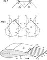
- FIG 7 shows a wave period 48 of the trailing edge waveform of FIG 6 .
- a period is defined between any two consecutive corresponding points on a waveform -- for example between two adjacent peaks 49 or two adjacent valleys.
- the phase of a waveform is a proportion of a period, such as a percentage thereof, or alternately an angle thereof when waveform is sinusoidal.
- the illustrated phases 44 and 46 are shown by example as 75% and 25% respectively of the indicated period 48.
- FIG 8 is a plan view of a portion of a serrated trailing edge 42 with vortices 27, 29 aligned with serrations in accordance with an aspect of the invention.
- the trailing edge crossing points of the vortices 27, 29 may be defined by the crossing points of vortex center lines 45, 47. These centerlines may be determined by placement of the respective VGs 26, 28 ( FIG 6 ) aligned in a relative airflow direction with a respective phase 44, 46 of the waveform.
- Each vortex generator may be designed to produce a downstream vortical flow that crosses the trailing edge at an angle C of less than 30 degrees from parallel with the trailing edge, or less than 20 degrees.
- Such a small crossing angle reduces the abruptness of change in acoustic impedance between the suction side and pressure side flows as they merge at the trailing edge. This reduces the intensity of acoustic scattering due to the impedance mismatch, thus reducing noise and drag.
- FIG 9 is a perspective view of a blade airfoil 80 with a spanwise dimension 51. It has an aft portion with alternating chordwise ridges 52 and troughs 54 on the suction side 22. It also has opposed troughs 56 and ridges 58 on the pressure side 60. The pressure and suction side ridges and troughs nest at the trailing edge 42, to form a waveform as viewed from behind.
- a spanwise sequence 62 of sunken vortex generators 64, 66 is formed by drop-offs at the upstream ends of the troughs 54 on the suction side surface 22. These VGs do not have a pressure side or leading edge, so they create smoother, quieter vortices and less drag compared to prior VGs. They generate counter-rotating vortices that progress downstream in the suction side troughs 54 as later shown.
- a chord line 68 may be defined from the leading edge to a zero line 70 midway between the peaks and valleys of the waveform trail
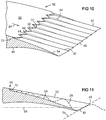
- FIG 10 is a perspective view of an aft portion of a blade airfoil 82 with alternating ridges 52 and troughs 54 aligned with the relative airflow 24, and ending in a trailing edge 42 having a waveform profile as viewed from behind and as viewed from above.
- the trailing edge 42 may be disposed in a plane that is oblique to the chord line. This results in trailing edge serrations as viewed from above.
- a spanwise sequence of sunken vortex generators 64, 66 is formed by drop-offs 72 at the upstream ends of the troughs 54 on the suction side surface 22 of the blade 82. These VGs may have a suction side 32 with a top edge flush with the suction side 22 of the blade.
- the VGs have no pressure side, and thus no leading edge. They may taper to a point 73 at the ridge 52. Thus, they have no trailing edge. This means they have no surfaces other than the vortex-generating surface 32, thus minimizing drag and noise. Alternately, standard vortex generators may be used in troughs that merge smoothly forward into the suction side surface 22.
- FIG 11 is a transverse sectional view of the blade 82 taken through a trough 54 of FIG 10 .
- the trailing edge 42 is disposed in a plane 74 that is oblique to the chord line 68, resulting in serrations as viewed from above.
- the oblique plane 74 may lean away from the suction side 22 by at least 45 degrees relative to a plane normal to the chord line 68.
- a sunken VG 66 creates a vortex 29 in the trough.
- the VG may be designed to create a vortex 29 that may extend in diameter substantially to the ridge 52 over at least most of a length of the ridge 52, such as over at least 75% of the length of the ridge 52, thus substantially filling the trough 54.
- the shape and direction of the vortex 29 can be designed by the shape and angle of the VG 66.
- the VG may have a drop-off 72 with a rounded edge to cause a smooth roll-over of airflow into a vortex 29 that hugs the surface of the trough 54.
- the VG may be designed to produce a vortical flow 29 that crosses the trailing edge 42 at an angle of less than 30 degrees from parallel therewith, or less than 20 degrees.
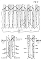
- FIG 12 is a plan view of a spanwise sequence of alternately angled first and second sunken vortex generators 64, 66 on the suction side 22 of an airfoil at the front of chordwise troughs 54 therein.
- the trailing edge 42 is serrated, forming a waveform profile in this view, such as a triangular, sinusoidal, or trapezoidal waveform.
- Each VG 26, 28 is designed to generate a respective vortex 27, 29 that crosses the waveform at a predetermined phase 44, 46. Dashed lines indicate the path of an airflow molecule within each vortex as seen in this 2-dimensional view.
- FIG 13 is a plan view of a single trough 54 between two ridges 52.
- the vortex generators may be convex as shown to shed the vortices 27, 29 earlier than if they were straight, thus shedding the vortices closer to the center of the trough 54.
- FIG 14 shows a pressure side portion of the blade directly below the suction side trough of FIG 13 , in an embodiment with a pressure side ridge 52P opposite the suction side trough 54 of FIG 13 , and pressure side troughs 54P opposite the suction side ridges 52 of FIG 13 .
- Pressure side vortex generators 64P, 66P may be designed to create respective pressure side vortices 27P, 29P within the pressure side troughs 54P with vortical flows that cross the trailing edge 42 at a predetermined phase 44, 46 of the waveform trailing edge 42 at an angle of less than 30 degrees from parallel with the trailing edge, or less than 20 degrees and, in some embodiments, in the same direction as the respective suction side vortical flows 27, 29 of FIG 13 .
- pressure and suction side vortex generators may be positioned so that the flows exiting the trailing edge from the pressure and suction sides are at a specific predetermined angle relative to each other at respective points along the trailing edge. Moreover, the relative alignment of the pressure and suction side flows exiting the trailing edge may be varied along the spanwise length of the trailing edge. Sunken vortex generators are shown in this embodiment. In another embodiment the pressure side vortex generators may be surface mounted.
- FIG 15 shows a pressure side 61 directly below the suction side portion of FIG 6 , in an embodiment with pressure side vortex generators 26P, 28P designed to create respective pressure side vortices 27P, 29P with vortical flows that cross the trailing edge 42 at a predetermined phase 44, 46 of the waveform trailing edge 42 at an angle of less than 30 degrees from parallel with the trailing edge, or less than 20 degrees, and in the same direction as the respective suction side vortical flows 27, 29 of FIG 6 .
- This causes the pressure and suction side flows to merge smoothly.
- a pressure side relative airflow 24P is shown.
Landscapes
- Engineering & Computer Science (AREA)
- Life Sciences & Earth Sciences (AREA)
- Sustainable Development (AREA)
- Sustainable Energy (AREA)
- Chemical & Material Sciences (AREA)
- Combustion & Propulsion (AREA)
- Mechanical Engineering (AREA)
- General Engineering & Computer Science (AREA)
- Physics & Mathematics (AREA)
- Fluid Mechanics (AREA)
- Wind Motors (AREA)
- Structures Of Non-Positive Displacement Pumps (AREA)
Claims (11)
- Pale d'éolienne (20) comprenant un alignement prédéterminé de caractéristiques générant un vortex, avec des caractéristiques de bord de fuite par rapport à un chemin d'écoulement d'air,
les caractéristiques de bord de fuite comprenant une séquence de pics et de vallées en alternance formant un bord de fuite (42) avec des dentelures comprenant une forme d'onde, vu depuis l'arrière de la pale ;
caractérisée en ce que
les caractéristiques répétées générant un vortex comprennent une séquence, sur l'envergure, de générateurs de vortex (26, 28, 26P, 28P, 64, 66, 64P, 66P) conçus pour produire des vortex aval respectifs (27, 29, 27P, 29P) sur un côté d'aspiration (22) de la pale, qui intersectent la forme d'onde au niveau d'une phase commune de ceux-ci, chacun des générateurs de vortex (26, 28, 26P, 28P, 64, 66, 64P, 66P) étant conçu pour produire un écoulement de vortex aval qui intersecte le bord de fuite (42) suivant un angle inférieur à 30 degrés à partir d'une parallèle au bord de fuite (42) . - Pale d'éolienne (20) selon la revendication 1, dans laquelle :
chacun des générateurs de vortex (26, 28, 26P, 28P, 64, 66, 64P, 66P) est aligné par rapport au chemin d'écoulement d'air avec une période respective de la forme d'onde au niveau d'une phase commune de ceux-ci. - Pale d'éolienne (20) selon la revendication 1 ou 2, dans laquelle :les générateurs de vortex (26, 28, 26P, 28P, 64, 66, 64P, 66P) comprennent une séquence, sur l'envergure, de paires de premiers et deuxièmes générateurs de vortex (26, 28, 26P, 28P, 64, 66, 64P, 66P) conçus pour produire des premiers et deuxièmes vortex tournant respectivement en sens opposés (27, 29, 27P, 29P) ;les premiers générateurs de vortex (26, 28, 26P, 28P, 64, 66, 64P, 66P) sont alignés par rapport au chemin d'écoulement d'air avec des périodes respectives de la forme d'onde au niveau d'une première phase commune de ceux-ci, etles deuxièmes générateurs de vortex (26, 28, 26P, 28P, 64, 66, 64P, 66P) sont alignés par rapport au chemin d'écoulement d'air avec les périodes respectives de la forme d'onde au niveau d'une deuxième phase commune de ceux-ci.
- Pale d'éolienne (20) selon la revendication 1 ou 2, dans laquelle :les caractéristiques répétées générant un vortex comprennent une séquence, sur l'envergure, de générateurs de vortex inclinés en alternance (26, 28, 26P, 28P, 64, 66, 64P, 66P) sur un côté d'aspiration (22) de la pale, conçus pour produire une séquence, sur l'envergure, de paires de premiers et deuxièmes vortex tournant en sens opposés (27, 29, 27P, 29P), respectivement, en alternance, en aval de ceux-ci ;chacun des premiers vortex (27, 29, 27P, 29P) intersecte une période respective de la forme d'onde au niveau d'une première phase commune de ceux-ci ; etchacun des deuxièmes vortex (27, 29, 27P, 29P) intersecte la période respective de la forme d'onde au niveau d'une deuxième phase commune de ceux-ci.
- Pale d'éolienne (20) selon l'une quelconque des revendications 1 à 4, dans laquelle les caractéristiques de bord de fuite sont formées par des arêtes et des creux en alternance sur un côté d'aspiration (22) de la pale, orientés par rapport au chemin d'écoulement d'air et se terminant par un bord de fuite (42) avec des pics et des vallées respectivement en alternance, définissant une forme d'onde, vu depuis l'arrière de la pale, les caractéristiques générant un vortex comprenant, sur l'envergure, une série de générateurs de vortex (26, 28, 26P, 28P, 64, 66, 64P, 66P), dont chacun est aligné dans le chemin d'écoulement d'air relatif avec une partie de l'un respectif des creux.
- Pale d'éolienne (20) selon la revendication 5, dans laquelle les générateurs de vortex (26, 28, 26P, 28P, 64, 66, 64P, 66P) sont conçus pour créer les vortex (27, 29, 27P, 29P) de manière à ce qu'ils s'étendent, en diamètre, jusqu'à une hauteur du creux supérieure à au moins 75 % d'une longueur du creux.
- Pale d'éolienne (20) selon la revendication 5, dans laquelle chaque générateur de vortex est renfoncé dans le côté d'aspiration (22) de la pale, et est formé par un côté d'aspiration (32) du générateur de vortex avec un bord supérieur en affleurement avec le côté d'aspiration (22) de la pale, le générateur de vortex n'ayant pas de surface côté pression.
- Pale d'éolienne (20) selon la revendication 7, dans lequel le côté d'aspiration (32) du générateur de vortex est convexe, vu dans une vue en plan de la pale.
- Pale d'éolienne (20) selon la revendication 7, dans lequel le côté d'aspiration (22) du générateur de vortex s'effile jusqu'à une pointe (73) au niveau d'une arête adjacente (52), le générateur de vortex n'ayant pas de bord de fuite.
- Pale d'éolienne (20) selon la revendication 1, dans lequel :
les caractéristiques générant un vortex comprennent une première séquence, sur l'envergure, de générateurs de vortex (26, 28, 26P, 28P, 64, 66, 64P, 66P) sur un côté d'aspiration (22) de la pale, et une deuxième séquence, sur l'envergure, de générateurs de vortex (26, 28, 26P, 28P, 64, 66, 64P, 66P) sur un côté de pression de la pale, chacun des générateurs de vortex (26, 28, 26P, 28P, 64, 66, 64P, 66P) étant aligné par rapport au chemin de flux d'air avec une période respective de la forme d'onde au niveau d'une phase commune de ceux-ci. - Pale d'éolienne (20) selon la revendication 10, dans laquelle chacun des générateurs de vortex du côté d'aspiration et du côté de pression (26, 28, 26P, 28P, 64, 66, 64P, 66P) est conçu pour produire un écoulement tourbillonnaire aval respectif qui intercecte le bord de fuite (42) suivant un angle inférieur à 30 degrés à partir d'une parallèle à celui-ci.
Applications Claiming Priority (1)
| Application Number | Priority Date | Filing Date | Title |
|---|---|---|---|
| US14/251,943 US9476406B2 (en) | 2014-04-14 | 2014-04-14 | Vortex generators aligned with trailing edge features on wind turbine blade |
Publications (2)
| Publication Number | Publication Date |
|---|---|
| EP2933475A1 EP2933475A1 (fr) | 2015-10-21 |
| EP2933475B1 true EP2933475B1 (fr) | 2018-10-17 |
Family
ID=52824163
Family Applications (1)
| Application Number | Title | Priority Date | Filing Date |
|---|---|---|---|
| EP15163469.8A Active EP2933475B1 (fr) | 2014-04-14 | 2015-04-14 | Générateurs de vortex alignés avec des caractéristiques de bord de fuite sur une pale d'éolienne |
Country Status (3)
| Country | Link |
|---|---|
| US (1) | US9476406B2 (fr) |
| EP (1) | EP2933475B1 (fr) |
| CN (1) | CN104976075B (fr) |
Cited By (1)
| Publication number | Priority date | Publication date | Assignee | Title |
|---|---|---|---|---|
| US11525430B2 (en) | 2021-01-07 | 2022-12-13 | Nordex Energy Se & Co. Kg | Wind turbine rotor blade with two rows of vortex generators |
Families Citing this family (24)
| Publication number | Priority date | Publication date | Assignee | Title |
|---|---|---|---|---|
| ES2482615T3 (es) * | 2011-02-04 | 2014-08-04 | Lm Wp Patent Holding A/S | Dispositivo generador de torbellinos con secciones ahusadas para una turbina eólica |
| DK2739528T3 (da) * | 2011-07-22 | 2019-12-09 | Lm Wp Patent Holding As | Vortexgenerator-arrangement til en bæreplansprofil |
| EP2927481B1 (fr) * | 2014-03-31 | 2021-09-22 | Siemens Gamesa Renewable Energy A/S | Pale de rotor pour éolienne |
| WO2015167604A1 (fr) * | 2014-04-29 | 2015-11-05 | Virginia Tech Intellectual Properties, Inc. | Traitement de surface de réduction de bruit pour surface portante |
| PL3164599T3 (pl) * | 2014-07-03 | 2019-09-30 | Lm Wp Patent Holding A/S | Łopata turbiny wiatrowej |
| WO2017180192A1 (fr) * | 2016-04-15 | 2017-10-19 | Siemens Aktiengesellschaft | Pale de rotor à bord de fuite dentelé |
| CN105485743B (zh) * | 2016-01-15 | 2017-11-03 | 宁波方太厨具有限公司 | 一种具有降噪机构的吸油烟机 |
| DK3431754T3 (da) * | 2016-02-12 | 2020-10-26 | Lm Wp Patent Holding As | Savtakket bagkantspanel til en vindmøllevinge |
| EP3219980B1 (fr) * | 2016-03-16 | 2019-01-02 | Siemens Aktiengesellschaft | Conduit d'air de bord de fuite d'une pale de rotor d'éolienne |
| EP3267031B1 (fr) | 2016-07-05 | 2019-06-12 | Siemens Gamesa Renewable Energy A/S | Aube de rotor d'éolienne avec générateurs de vortex |
| EP3330614B1 (fr) | 2016-11-30 | 2019-10-02 | Ansaldo Energia Switzerland AG | Dispositif générateur de tourbillons |
| DE112017006296B4 (de) * | 2017-01-24 | 2023-02-02 | Hitachi, Ltd. | Fluidvorrichtung |
| US10465652B2 (en) | 2017-01-26 | 2019-11-05 | General Electric Company | Vortex generators for wind turbine rotor blades having noise-reducing features |
| EP3406892B1 (fr) * | 2017-05-22 | 2025-11-19 | LM Wind Power A/S | Pale de turbine éolienne comprenant un dispositif de réduction de bruit |
| CN112020608B (zh) * | 2018-04-30 | 2024-05-10 | Lm风力发电公司 | 具有降噪特征的用于风力涡轮转子叶片的涡流发生器 |
| ES3037885T3 (en) * | 2018-06-27 | 2025-10-07 | Siemens Gamesa Renewable Energy As | Aerodynamic structure |
| ES2843742T3 (es) | 2018-06-27 | 2021-07-20 | Siemens Gamesa Renewable Energy As | Estructura aerodinámica |
| CN110107463B (zh) * | 2019-05-27 | 2020-06-02 | 上海电气风电集团股份有限公司 | 一种渐缩截面涡流发生器及其安装方法 |
| JP7277316B2 (ja) * | 2019-08-30 | 2023-05-18 | 三菱重工業株式会社 | 風車翼装置及び風車翼アタッチメント部材 |
| KR102192061B1 (ko) * | 2019-12-30 | 2020-12-16 | 서울대학교산학협력단 | 블레이드 소음 저감 장치 |
| RU2749524C1 (ru) * | 2020-02-28 | 2021-06-11 | Сергей Николаевич Низов | Аэрогидродинамическая поверхность, группа вихрегенераторов и способ установки группы вихрегенераторов |
| CN112943525B (zh) * | 2021-03-29 | 2023-04-07 | 西安交通大学 | 一种耦合风力机仿生叶片结构 |
| WO2023139177A1 (fr) | 2022-01-19 | 2023-07-27 | Power Curve Aps | Générateur de vortex |
| CN116816588A (zh) * | 2023-07-25 | 2023-09-29 | 三一重能股份有限公司 | 叶片尾缘结构、风电叶片及风力发电机组 |
Family Cites Families (31)
| Publication number | Priority date | Publication date | Assignee | Title |
|---|---|---|---|---|
| US3578264A (en) | 1968-07-09 | 1971-05-11 | Battelle Development Corp | Boundary layer control of flow separation and heat exchange |
| US4655419A (en) | 1984-12-31 | 1987-04-07 | The Boeing Company | Vortex generator |
| US4830315A (en) | 1986-04-30 | 1989-05-16 | United Technologies Corporation | Airfoil-shaped body |
| US4813466A (en) * | 1986-12-17 | 1989-03-21 | Vehicle Systems Development Corporation | Support track for a wheeled vehicle |
| GB8829792D0 (en) * | 1988-12-21 | 1989-07-05 | Marconi Co Ltd | Noise reduction method |
| US5058837A (en) | 1989-04-07 | 1991-10-22 | Wheeler Gary O | Low drag vortex generators |
| US5088665A (en) | 1989-10-31 | 1992-02-18 | The United States Of America As Represented By The Administrator Of The National Aeronautics And Space Administration | Serrated trailing edges for improving lift and drag characteristics of lifting surfaces |
| US7059833B2 (en) | 2001-11-26 | 2006-06-13 | Bonus Energy A/S | Method for improvement of the efficiency of a wind turbine rotor |
| JP2003254225A (ja) * | 2002-03-05 | 2003-09-10 | Ebara Corp | 風車の気流騒音低減装置 |
| DK200300670A (da) | 2003-05-05 | 2004-11-06 | Lm Glasfiber As | Vindmölleving med opdriftsregulerende organer |
| US7604461B2 (en) | 2005-11-17 | 2009-10-20 | General Electric Company | Rotor blade for a wind turbine having aerodynamic feature elements |
| PT2007981T (pt) * | 2006-04-02 | 2021-02-11 | Wobben Properties Gmbh | Turbina eólica com pá esbelta |
| DE102006043462A1 (de) * | 2006-09-15 | 2008-03-27 | Deutsches Zentrum für Luft- und Raumfahrt e.V. | Aerodynamisches Bauteil mit einer gewellten Hinterkante |
| CN101680423B (zh) | 2007-03-20 | 2012-01-11 | 维斯塔斯风力系统有限公司 | 具涡流发生器的风轮机叶片 |
| ES2345583B1 (es) * | 2007-05-31 | 2011-07-28 | GAMESA INNOVATION & TECHNOLOGY, S.L. | Pala de aerogenerador con dispositivos anti-ruido. |
| US20090074585A1 (en) | 2007-09-19 | 2009-03-19 | General Electric Company | Wind turbine blades with trailing edge serrations |
| EP2270312A1 (fr) * | 2009-07-01 | 2011-01-05 | PEM-Energy Oy | Construction aréo- ou hydrodynamique |
| CN201461226U (zh) | 2009-08-05 | 2010-05-12 | 中国科学院工程热物理研究所 | 一种叶片 |
| US8439628B2 (en) * | 2010-01-06 | 2013-05-14 | General Electric Company | Heat transfer enhancement in internal cavities of turbine engine airfoils |
| US8047801B2 (en) | 2010-06-23 | 2011-11-01 | General Electric Company | Wind turbine blades with aerodynamic vortex elements |
| DE102010026588B4 (de) * | 2010-07-08 | 2012-06-14 | Nordex Energy Gmbh | Windenergieanlagenrotorblatt mit optimierter Hinterkante |
| US8083488B2 (en) | 2010-08-23 | 2011-12-27 | General Electric Company | Blade extension for rotor blade in wind turbine |
| US8523515B2 (en) * | 2010-11-15 | 2013-09-03 | General Electric Company | Noise reducer for rotor blade in wind turbine |
| EP2548801A1 (fr) * | 2011-07-22 | 2013-01-23 | LM Wind Power A/S | Pale d'éolienne comprenant des générateurs de vortex |
| EP2548800A1 (fr) * | 2011-07-22 | 2013-01-23 | LM Wind Power A/S | Procédés pour rééquiper des générateurs de vortex sur une pale d'éolienne |
| US8834127B2 (en) * | 2011-09-09 | 2014-09-16 | General Electric Company | Extension for rotor blade in wind turbine |
| US8777580B2 (en) * | 2011-11-02 | 2014-07-15 | Siemens Aktiengesellschaft | Secondary airfoil mounted on stall fence on wind turbine blade |
| US9341158B2 (en) | 2011-12-08 | 2016-05-17 | Inventus Holdings, Llc | Quiet wind turbine blade |
| US8430638B2 (en) * | 2011-12-19 | 2013-04-30 | General Electric Company | Noise reducer for rotor blade in wind turbine |
| WO2014048581A1 (fr) | 2012-09-25 | 2014-04-03 | Siemens Aktiengesellschaft | Pale d'éolienne dotée d'un dispositif de réduction du bruit |
| EP2713044B2 (fr) * | 2012-09-28 | 2022-12-07 | Siemens Gamesa Renewable Energy A/S | Pale de rotor d'éolienne |
-
2014
- 2014-04-14 US US14/251,943 patent/US9476406B2/en active Active
-
2015
- 2015-04-14 EP EP15163469.8A patent/EP2933475B1/fr active Active
- 2015-04-14 CN CN201510176743.9A patent/CN104976075B/zh active Active
Non-Patent Citations (1)
| Title |
|---|
| None * |
Cited By (1)
| Publication number | Priority date | Publication date | Assignee | Title |
|---|---|---|---|---|
| US11525430B2 (en) | 2021-01-07 | 2022-12-13 | Nordex Energy Se & Co. Kg | Wind turbine rotor blade with two rows of vortex generators |
Also Published As
| Publication number | Publication date |
|---|---|
| US20150292476A1 (en) | 2015-10-15 |
| EP2933475A1 (fr) | 2015-10-21 |
| US9476406B2 (en) | 2016-10-25 |
| CN104976075B (zh) | 2020-04-10 |
| CN104976075A (zh) | 2015-10-14 |
Similar Documents
| Publication | Publication Date | Title |
|---|---|---|
| EP2933475B1 (fr) | Générateurs de vortex alignés avec des caractéristiques de bord de fuite sur une pale d'éolienne | |
| EP2921697B1 (fr) | Modifications de bord de fuite pour pale d'éolienne | |
| EP2824320B1 (fr) | Générateur de vortex à bruit réduit pour pale d'éolienne | |
| CN109416017B (zh) | 具有锯齿状后缘的转子叶片 | |
| EP2851555B1 (fr) | Pale de rotor de turbine éolienne avec extension dentelée | |
| CN102414440B (zh) | 功率输出增大的风轮机 | |
| US10227963B2 (en) | Rotor blade for a wind turbine, and wind turbine field | |
| CN101883922B (zh) | 具有包括交叉子通道的凹陷式边界层控制装置的风力涡轮机叶片 | |
| CN106536920B (zh) | 风能设备转子叶片,转子叶片后缘和用于制造风能设备转子叶片的方法以及风能设备 | |
| EP3426914B1 (fr) | Pale de rotor à bord de fuite dentelé | |
| CN106414999A (zh) | 用于风力机转子叶片的降噪装置 | |
| CN106574600B (zh) | 风能设备转子叶片,转子叶片尖端后缘,风能设备转子叶片的制造方法和风能设备 | |
| CN108603486A (zh) | 风能设备的转子叶片和风能设备 | |
| EP3181895A1 (fr) | Système à plaque de séparation pour une pale de turbine éolienne dentelée | |
| CN104736844A (zh) | 风能设施 | |
| GB2507493A (en) | Air movement fan with protrusions on the leading and trailing edges of the blades | |
| US12018638B2 (en) | Wind turbine serrations with upstream extension | |
| EP3098436A1 (fr) | Volet de réduction de bruit avec une ouverture |
Legal Events
| Date | Code | Title | Description |
|---|---|---|---|
| PUAI | Public reference made under article 153(3) epc to a published international application that has entered the european phase |
Free format text: ORIGINAL CODE: 0009012 |
|
| AK | Designated contracting states |
Kind code of ref document: A1 Designated state(s): AL AT BE BG CH CY CZ DE DK EE ES FI FR GB GR HR HU IE IS IT LI LT LU LV MC MK MT NL NO PL PT RO RS SE SI SK SM TR |
|
| AX | Request for extension of the european patent |
Extension state: BA ME |
|
| 17P | Request for examination filed |
Effective date: 20160421 |
|
| RBV | Designated contracting states (corrected) |
Designated state(s): AL AT BE BG CH CY CZ DE DK EE ES FI FR GB GR HR HU IE IS IT LI LT LU LV MC MK MT NL NO PL PT RO RS SE SI SK SM TR |
|
| RAP1 | Party data changed (applicant data changed or rights of an application transferred) |
Owner name: SIEMENS AKTIENGESELLSCHAFT |
|
| RIC1 | Information provided on ipc code assigned before grant |
Ipc: F03D 1/06 20060101AFI20180131BHEP |
|
| GRAP | Despatch of communication of intention to grant a patent |
Free format text: ORIGINAL CODE: EPIDOSNIGR1 |
|
| STAA | Information on the status of an ep patent application or granted ep patent |
Free format text: STATUS: GRANT OF PATENT IS INTENDED |
|
| INTG | Intention to grant announced |
Effective date: 20180409 |
|
| GRAS | Grant fee paid |
Free format text: ORIGINAL CODE: EPIDOSNIGR3 |
|
| GRAJ | Information related to disapproval of communication of intention to grant by the applicant or resumption of examination proceedings by the epo deleted |
Free format text: ORIGINAL CODE: EPIDOSDIGR1 |
|
| GRAL | Information related to payment of fee for publishing/printing deleted |
Free format text: ORIGINAL CODE: EPIDOSDIGR3 |
|
| STAA | Information on the status of an ep patent application or granted ep patent |
Free format text: STATUS: REQUEST FOR EXAMINATION WAS MADE |
|
| INTC | Intention to grant announced (deleted) | ||
| GRAR | Information related to intention to grant a patent recorded |
Free format text: ORIGINAL CODE: EPIDOSNIGR71 |
|
| STAA | Information on the status of an ep patent application or granted ep patent |
Free format text: STATUS: GRANT OF PATENT IS INTENDED |
|
| GRAA | (expected) grant |
Free format text: ORIGINAL CODE: 0009210 |
|
| STAA | Information on the status of an ep patent application or granted ep patent |
Free format text: STATUS: THE PATENT HAS BEEN GRANTED |
|
| INTG | Intention to grant announced |
Effective date: 20180906 |
|
| AK | Designated contracting states |
Kind code of ref document: B1 Designated state(s): AL AT BE BG CH CY CZ DE DK EE ES FI FR GB GR HR HU IE IS IT LI LT LU LV MC MK MT NL NO PL PT RO RS SE SI SK SM TR |
|
| REG | Reference to a national code |
Ref country code: GB Ref legal event code: FG4D |
|
| REG | Reference to a national code |
Ref country code: CH Ref legal event code: EP |
|
| REG | Reference to a national code |
Ref country code: IE Ref legal event code: FG4D |
|
| REG | Reference to a national code |
Ref country code: DE Ref legal event code: R096 Ref document number: 602015018152 Country of ref document: DE Ref country code: AT Ref legal event code: REF Ref document number: 1054339 Country of ref document: AT Kind code of ref document: T Effective date: 20181115 |
|
| REG | Reference to a national code |
Ref country code: NL Ref legal event code: MP Effective date: 20181017 |
|
| REG | Reference to a national code |
Ref country code: LT Ref legal event code: MG4D |
|
| REG | Reference to a national code |
Ref country code: AT Ref legal event code: MK05 Ref document number: 1054339 Country of ref document: AT Kind code of ref document: T Effective date: 20181017 |
|
| PG25 | Lapsed in a contracting state [announced via postgrant information from national office to epo] |
Ref country code: NL Free format text: LAPSE BECAUSE OF FAILURE TO SUBMIT A TRANSLATION OF THE DESCRIPTION OR TO PAY THE FEE WITHIN THE PRESCRIBED TIME-LIMIT Effective date: 20181017 |
|
| PG25 | Lapsed in a contracting state [announced via postgrant information from national office to epo] |
Ref country code: ES Free format text: LAPSE BECAUSE OF FAILURE TO SUBMIT A TRANSLATION OF THE DESCRIPTION OR TO PAY THE FEE WITHIN THE PRESCRIBED TIME-LIMIT Effective date: 20181017 Ref country code: HR Free format text: LAPSE BECAUSE OF FAILURE TO SUBMIT A TRANSLATION OF THE DESCRIPTION OR TO PAY THE FEE WITHIN THE PRESCRIBED TIME-LIMIT Effective date: 20181017 Ref country code: PL Free format text: LAPSE BECAUSE OF FAILURE TO SUBMIT A TRANSLATION OF THE DESCRIPTION OR TO PAY THE FEE WITHIN THE PRESCRIBED TIME-LIMIT Effective date: 20181017 Ref country code: LV Free format text: LAPSE BECAUSE OF FAILURE TO SUBMIT A TRANSLATION OF THE DESCRIPTION OR TO PAY THE FEE WITHIN THE PRESCRIBED TIME-LIMIT Effective date: 20181017 Ref country code: IS Free format text: LAPSE BECAUSE OF FAILURE TO SUBMIT A TRANSLATION OF THE DESCRIPTION OR TO PAY THE FEE WITHIN THE PRESCRIBED TIME-LIMIT Effective date: 20190217 Ref country code: FI Free format text: LAPSE BECAUSE OF FAILURE TO SUBMIT A TRANSLATION OF THE DESCRIPTION OR TO PAY THE FEE WITHIN THE PRESCRIBED TIME-LIMIT Effective date: 20181017 Ref country code: BG Free format text: LAPSE BECAUSE OF FAILURE TO SUBMIT A TRANSLATION OF THE DESCRIPTION OR TO PAY THE FEE WITHIN THE PRESCRIBED TIME-LIMIT Effective date: 20190117 Ref country code: LT Free format text: LAPSE BECAUSE OF FAILURE TO SUBMIT A TRANSLATION OF THE DESCRIPTION OR TO PAY THE FEE WITHIN THE PRESCRIBED TIME-LIMIT Effective date: 20181017 Ref country code: NO Free format text: LAPSE BECAUSE OF FAILURE TO SUBMIT A TRANSLATION OF THE DESCRIPTION OR TO PAY THE FEE WITHIN THE PRESCRIBED TIME-LIMIT Effective date: 20190117 Ref country code: AT Free format text: LAPSE BECAUSE OF FAILURE TO SUBMIT A TRANSLATION OF THE DESCRIPTION OR TO PAY THE FEE WITHIN THE PRESCRIBED TIME-LIMIT Effective date: 20181017 |
|
| REG | Reference to a national code |
Ref country code: DE Ref legal event code: R081 Ref document number: 602015018152 Country of ref document: DE Owner name: SIEMENS GAMESA RENEWABLE ENERGY A/S, DK Free format text: FORMER OWNER: SIEMENS AKTIENGESELLSCHAFT, 80333 MUENCHEN, DE |
|
| RAP2 | Party data changed (patent owner data changed or rights of a patent transferred) |
Owner name: SIEMENS GAMESA RENEWABLE ENERGY A/S |
|
| PG25 | Lapsed in a contracting state [announced via postgrant information from national office to epo] |
Ref country code: RS Free format text: LAPSE BECAUSE OF FAILURE TO SUBMIT A TRANSLATION OF THE DESCRIPTION OR TO PAY THE FEE WITHIN THE PRESCRIBED TIME-LIMIT Effective date: 20181017 Ref country code: GR Free format text: LAPSE BECAUSE OF FAILURE TO SUBMIT A TRANSLATION OF THE DESCRIPTION OR TO PAY THE FEE WITHIN THE PRESCRIBED TIME-LIMIT Effective date: 20190118 Ref country code: PT Free format text: LAPSE BECAUSE OF FAILURE TO SUBMIT A TRANSLATION OF THE DESCRIPTION OR TO PAY THE FEE WITHIN THE PRESCRIBED TIME-LIMIT Effective date: 20190217 Ref country code: AL Free format text: LAPSE BECAUSE OF FAILURE TO SUBMIT A TRANSLATION OF THE DESCRIPTION OR TO PAY THE FEE WITHIN THE PRESCRIBED TIME-LIMIT Effective date: 20181017 Ref country code: SE Free format text: LAPSE BECAUSE OF FAILURE TO SUBMIT A TRANSLATION OF THE DESCRIPTION OR TO PAY THE FEE WITHIN THE PRESCRIBED TIME-LIMIT Effective date: 20181017 |
|
| REG | Reference to a national code |
Ref country code: DE Ref legal event code: R097 Ref document number: 602015018152 Country of ref document: DE |
|
| PG25 | Lapsed in a contracting state [announced via postgrant information from national office to epo] |
Ref country code: DK Free format text: LAPSE BECAUSE OF FAILURE TO SUBMIT A TRANSLATION OF THE DESCRIPTION OR TO PAY THE FEE WITHIN THE PRESCRIBED TIME-LIMIT Effective date: 20181017 Ref country code: IT Free format text: LAPSE BECAUSE OF FAILURE TO SUBMIT A TRANSLATION OF THE DESCRIPTION OR TO PAY THE FEE WITHIN THE PRESCRIBED TIME-LIMIT Effective date: 20181017 Ref country code: CZ Free format text: LAPSE BECAUSE OF FAILURE TO SUBMIT A TRANSLATION OF THE DESCRIPTION OR TO PAY THE FEE WITHIN THE PRESCRIBED TIME-LIMIT Effective date: 20181017 |
|
| PLBE | No opposition filed within time limit |
Free format text: ORIGINAL CODE: 0009261 |
|
| STAA | Information on the status of an ep patent application or granted ep patent |
Free format text: STATUS: NO OPPOSITION FILED WITHIN TIME LIMIT |
|
| PG25 | Lapsed in a contracting state [announced via postgrant information from national office to epo] |
Ref country code: RO Free format text: LAPSE BECAUSE OF FAILURE TO SUBMIT A TRANSLATION OF THE DESCRIPTION OR TO PAY THE FEE WITHIN THE PRESCRIBED TIME-LIMIT Effective date: 20181017 Ref country code: SK Free format text: LAPSE BECAUSE OF FAILURE TO SUBMIT A TRANSLATION OF THE DESCRIPTION OR TO PAY THE FEE WITHIN THE PRESCRIBED TIME-LIMIT Effective date: 20181017 Ref country code: SM Free format text: LAPSE BECAUSE OF FAILURE TO SUBMIT A TRANSLATION OF THE DESCRIPTION OR TO PAY THE FEE WITHIN THE PRESCRIBED TIME-LIMIT Effective date: 20181017 Ref country code: EE Free format text: LAPSE BECAUSE OF FAILURE TO SUBMIT A TRANSLATION OF THE DESCRIPTION OR TO PAY THE FEE WITHIN THE PRESCRIBED TIME-LIMIT Effective date: 20181017 |
|
| REG | Reference to a national code |
Ref country code: GB Ref legal event code: 732E Free format text: REGISTERED BETWEEN 20190822 AND 20190828 |
|
| 26N | No opposition filed |
Effective date: 20190718 |
|
| PG25 | Lapsed in a contracting state [announced via postgrant information from national office to epo] |
Ref country code: SI Free format text: LAPSE BECAUSE OF FAILURE TO SUBMIT A TRANSLATION OF THE DESCRIPTION OR TO PAY THE FEE WITHIN THE PRESCRIBED TIME-LIMIT Effective date: 20181017 |
|
| REG | Reference to a national code |
Ref country code: CH Ref legal event code: PL |
|
| REG | Reference to a national code |
Ref country code: BE Ref legal event code: MM Effective date: 20190430 |
|
| PG25 | Lapsed in a contracting state [announced via postgrant information from national office to epo] |
Ref country code: LU Free format text: LAPSE BECAUSE OF NON-PAYMENT OF DUE FEES Effective date: 20190414 Ref country code: MC Free format text: LAPSE BECAUSE OF FAILURE TO SUBMIT A TRANSLATION OF THE DESCRIPTION OR TO PAY THE FEE WITHIN THE PRESCRIBED TIME-LIMIT Effective date: 20181017 |
|
| PG25 | Lapsed in a contracting state [announced via postgrant information from national office to epo] |
Ref country code: LI Free format text: LAPSE BECAUSE OF NON-PAYMENT OF DUE FEES Effective date: 20190430 Ref country code: CH Free format text: LAPSE BECAUSE OF NON-PAYMENT OF DUE FEES Effective date: 20190430 |
|
| PG25 | Lapsed in a contracting state [announced via postgrant information from national office to epo] |
Ref country code: BE Free format text: LAPSE BECAUSE OF NON-PAYMENT OF DUE FEES Effective date: 20190430 |
|
| PG25 | Lapsed in a contracting state [announced via postgrant information from national office to epo] |
Ref country code: TR Free format text: LAPSE BECAUSE OF FAILURE TO SUBMIT A TRANSLATION OF THE DESCRIPTION OR TO PAY THE FEE WITHIN THE PRESCRIBED TIME-LIMIT Effective date: 20181017 |
|
| PG25 | Lapsed in a contracting state [announced via postgrant information from national office to epo] |
Ref country code: IE Free format text: LAPSE BECAUSE OF NON-PAYMENT OF DUE FEES Effective date: 20190414 |
|
| PG25 | Lapsed in a contracting state [announced via postgrant information from national office to epo] |
Ref country code: CY Free format text: LAPSE BECAUSE OF FAILURE TO SUBMIT A TRANSLATION OF THE DESCRIPTION OR TO PAY THE FEE WITHIN THE PRESCRIBED TIME-LIMIT Effective date: 20181017 |
|
| PG25 | Lapsed in a contracting state [announced via postgrant information from national office to epo] |
Ref country code: MT Free format text: LAPSE BECAUSE OF FAILURE TO SUBMIT A TRANSLATION OF THE DESCRIPTION OR TO PAY THE FEE WITHIN THE PRESCRIBED TIME-LIMIT Effective date: 20181017 Ref country code: HU Free format text: LAPSE BECAUSE OF FAILURE TO SUBMIT A TRANSLATION OF THE DESCRIPTION OR TO PAY THE FEE WITHIN THE PRESCRIBED TIME-LIMIT; INVALID AB INITIO Effective date: 20150414 |
|
| PG25 | Lapsed in a contracting state [announced via postgrant information from national office to epo] |
Ref country code: MK Free format text: LAPSE BECAUSE OF FAILURE TO SUBMIT A TRANSLATION OF THE DESCRIPTION OR TO PAY THE FEE WITHIN THE PRESCRIBED TIME-LIMIT Effective date: 20181017 |
|
| REG | Reference to a national code |
Ref country code: DE Ref legal event code: R082 Ref document number: 602015018152 Country of ref document: DE Representative=s name: SAUTHOFF, KARSTEN, DIPL.-ING. UNIV., DE |
|
| PGFP | Annual fee paid to national office [announced via postgrant information from national office to epo] |
Ref country code: DE Payment date: 20250428 Year of fee payment: 11 |
|
| PGFP | Annual fee paid to national office [announced via postgrant information from national office to epo] |
Ref country code: FR Payment date: 20250424 Year of fee payment: 11 |
|
| PGFP | Annual fee paid to national office [announced via postgrant information from national office to epo] |
Ref country code: GB Payment date: 20260323 Year of fee payment: 12 |