EP2933481A1 - Conduit d'air pour éolienne, éolienne, procédé de fabrication d'un conduit d'air et procédé de modernisation d'une installation éolienne avec un conduit d'air - Google Patents
Conduit d'air pour éolienne, éolienne, procédé de fabrication d'un conduit d'air et procédé de modernisation d'une installation éolienne avec un conduit d'air Download PDFInfo
- Publication number
- EP2933481A1 EP2933481A1 EP14164790.9A EP14164790A EP2933481A1 EP 2933481 A1 EP2933481 A1 EP 2933481A1 EP 14164790 A EP14164790 A EP 14164790A EP 2933481 A1 EP2933481 A1 EP 2933481A1
- Authority
- EP
- European Patent Office
- Prior art keywords
- air duct
- wind power
- power plant
- segments
- air
- Prior art date
- Legal status (The legal status is an assumption and is not a legal conclusion. Google has not performed a legal analysis and makes no representation as to the accuracy of the status listed.)
- Granted
Links
- 238000004519 manufacturing process Methods 0.000 title claims abstract description 12
- 238000000034 method Methods 0.000 title claims abstract description 7
- 238000009420 retrofitting Methods 0.000 title claims abstract description 6
- 230000008878 coupling Effects 0.000 claims description 12
- 238000010168 coupling process Methods 0.000 claims description 12
- 238000005859 coupling reaction Methods 0.000 claims description 12
- 239000000725 suspension Substances 0.000 claims description 6
- 239000003365 glass fiber Substances 0.000 claims description 2
- 229920000642 polymer Polymers 0.000 claims description 2
- XLYOFNOQVPJJNP-UHFFFAOYSA-N water Substances O XLYOFNOQVPJJNP-UHFFFAOYSA-N 0.000 description 9
- 238000001816 cooling Methods 0.000 description 3
- 210000001331 nose Anatomy 0.000 description 3
- 238000007789 sealing Methods 0.000 description 3
- 239000000443 aerosol Substances 0.000 description 2
- 238000004891 communication Methods 0.000 description 2
- 230000002787 reinforcement Effects 0.000 description 2
- 229910000831 Steel Inorganic materials 0.000 description 1
- 238000006243 chemical reaction Methods 0.000 description 1
- 238000010276 construction Methods 0.000 description 1
- 239000013013 elastic material Substances 0.000 description 1
- 239000012530 fluid Substances 0.000 description 1
- 239000006260 foam Substances 0.000 description 1
- 230000017525 heat dissipation Effects 0.000 description 1
- 239000002184 metal Substances 0.000 description 1
- 150000003839 salts Chemical class 0.000 description 1
- 239000010959 steel Substances 0.000 description 1
Images


Classifications
-
- F—MECHANICAL ENGINEERING; LIGHTING; HEATING; WEAPONS; BLASTING
- F03—MACHINES OR ENGINES FOR LIQUIDS; WIND, SPRING, OR WEIGHT MOTORS; PRODUCING MECHANICAL POWER OR A REACTIVE PROPULSIVE THRUST, NOT OTHERWISE PROVIDED FOR
- F03D—WIND MOTORS
- F03D80/00—Details, components or accessories not provided for in groups F03D1/00 - F03D17/00
- F03D80/80—Arrangement of components within nacelles or towers
-
- F—MECHANICAL ENGINEERING; LIGHTING; HEATING; WEAPONS; BLASTING
- F03—MACHINES OR ENGINES FOR LIQUIDS; WIND, SPRING, OR WEIGHT MOTORS; PRODUCING MECHANICAL POWER OR A REACTIVE PROPULSIVE THRUST, NOT OTHERWISE PROVIDED FOR
- F03D—WIND MOTORS
- F03D13/00—Assembly, mounting or commissioning of wind motors; Arrangements specially adapted for transporting wind motor components
- F03D13/20—Arrangements for mounting or supporting wind motors; Masts or towers for wind motors
-
- F—MECHANICAL ENGINEERING; LIGHTING; HEATING; WEAPONS; BLASTING
- F03—MACHINES OR ENGINES FOR LIQUIDS; WIND, SPRING, OR WEIGHT MOTORS; PRODUCING MECHANICAL POWER OR A REACTIVE PROPULSIVE THRUST, NOT OTHERWISE PROVIDED FOR
- F03D—WIND MOTORS
- F03D80/00—Details, components or accessories not provided for in groups F03D1/00 - F03D17/00
- F03D80/60—Cooling or heating of wind motors
-
- F—MECHANICAL ENGINEERING; LIGHTING; HEATING; WEAPONS; BLASTING
- F05—INDEXING SCHEMES RELATING TO ENGINES OR PUMPS IN VARIOUS SUBCLASSES OF CLASSES F01-F04
- F05B—INDEXING SCHEME RELATING TO WIND, SPRING, WEIGHT, INERTIA OR LIKE MOTORS, TO MACHINES OR ENGINES FOR LIQUIDS COVERED BY SUBCLASSES F03B, F03D AND F03G
- F05B2230/00—Manufacture
- F05B2230/60—Assembly methods
-
- F—MECHANICAL ENGINEERING; LIGHTING; HEATING; WEAPONS; BLASTING
- F05—INDEXING SCHEMES RELATING TO ENGINES OR PUMPS IN VARIOUS SUBCLASSES OF CLASSES F01-F04
- F05B—INDEXING SCHEME RELATING TO WIND, SPRING, WEIGHT, INERTIA OR LIKE MOTORS, TO MACHINES OR ENGINES FOR LIQUIDS COVERED BY SUBCLASSES F03B, F03D AND F03G
- F05B2230/00—Manufacture
- F05B2230/80—Repairing, retrofitting or upgrading methods
-
- F—MECHANICAL ENGINEERING; LIGHTING; HEATING; WEAPONS; BLASTING
- F05—INDEXING SCHEMES RELATING TO ENGINES OR PUMPS IN VARIOUS SUBCLASSES OF CLASSES F01-F04
- F05B—INDEXING SCHEME RELATING TO WIND, SPRING, WEIGHT, INERTIA OR LIKE MOTORS, TO MACHINES OR ENGINES FOR LIQUIDS COVERED BY SUBCLASSES F03B, F03D AND F03G
- F05B2260/00—Function
- F05B2260/20—Heat transfer, e.g. cooling
-
- F—MECHANICAL ENGINEERING; LIGHTING; HEATING; WEAPONS; BLASTING
- F05—INDEXING SCHEMES RELATING TO ENGINES OR PUMPS IN VARIOUS SUBCLASSES OF CLASSES F01-F04
- F05B—INDEXING SCHEME RELATING TO WIND, SPRING, WEIGHT, INERTIA OR LIKE MOTORS, TO MACHINES OR ENGINES FOR LIQUIDS COVERED BY SUBCLASSES F03B, F03D AND F03G
- F05B2260/00—Function
- F05B2260/60—Fluid transfer
- F05B2260/64—Aeration, ventilation, dehumidification or moisture removal of closed spaces
-
- F—MECHANICAL ENGINEERING; LIGHTING; HEATING; WEAPONS; BLASTING
- F05—INDEXING SCHEMES RELATING TO ENGINES OR PUMPS IN VARIOUS SUBCLASSES OF CLASSES F01-F04
- F05B—INDEXING SCHEME RELATING TO WIND, SPRING, WEIGHT, INERTIA OR LIKE MOTORS, TO MACHINES OR ENGINES FOR LIQUIDS COVERED BY SUBCLASSES F03B, F03D AND F03G
- F05B2280/00—Materials; Properties thereof
- F05B2280/20—Inorganic materials, e.g. non-metallic materials
- F05B2280/2001—Glass
-
- F—MECHANICAL ENGINEERING; LIGHTING; HEATING; WEAPONS; BLASTING
- F05—INDEXING SCHEMES RELATING TO ENGINES OR PUMPS IN VARIOUS SUBCLASSES OF CLASSES F01-F04
- F05B—INDEXING SCHEME RELATING TO WIND, SPRING, WEIGHT, INERTIA OR LIKE MOTORS, TO MACHINES OR ENGINES FOR LIQUIDS COVERED BY SUBCLASSES F03B, F03D AND F03G
- F05B2280/00—Materials; Properties thereof
- F05B2280/40—Organic materials
- F05B2280/4003—Synthetic polymers, e.g. plastics
-
- Y—GENERAL TAGGING OF NEW TECHNOLOGICAL DEVELOPMENTS; GENERAL TAGGING OF CROSS-SECTIONAL TECHNOLOGIES SPANNING OVER SEVERAL SECTIONS OF THE IPC; TECHNICAL SUBJECTS COVERED BY FORMER USPC CROSS-REFERENCE ART COLLECTIONS [XRACs] AND DIGESTS
- Y02—TECHNOLOGIES OR APPLICATIONS FOR MITIGATION OR ADAPTATION AGAINST CLIMATE CHANGE
- Y02E—REDUCTION OF GREENHOUSE GAS [GHG] EMISSIONS, RELATED TO ENERGY GENERATION, TRANSMISSION OR DISTRIBUTION
- Y02E10/00—Energy generation through renewable energy sources
- Y02E10/70—Wind energy
- Y02E10/72—Wind turbines with rotation axis in wind direction
-
- Y—GENERAL TAGGING OF NEW TECHNOLOGICAL DEVELOPMENTS; GENERAL TAGGING OF CROSS-SECTIONAL TECHNOLOGIES SPANNING OVER SEVERAL SECTIONS OF THE IPC; TECHNICAL SUBJECTS COVERED BY FORMER USPC CROSS-REFERENCE ART COLLECTIONS [XRACs] AND DIGESTS
- Y02—TECHNOLOGIES OR APPLICATIONS FOR MITIGATION OR ADAPTATION AGAINST CLIMATE CHANGE
- Y02P—CLIMATE CHANGE MITIGATION TECHNOLOGIES IN THE PRODUCTION OR PROCESSING OF GOODS
- Y02P70/00—Climate change mitigation technologies in the production process for final industrial or consumer products
- Y02P70/50—Manufacturing or production processes characterised by the final manufactured product
Definitions
- the invention relates to an air duct for a wind power plant configured to guide air along a circumference of a supporting structure, in particular a tower, of the wind power plant.
- the invention also relates to a wind power plant with an air guide and to methods of manufacturing an air guide for a wind power plant and retrofitting a wind power plant with an air guide.
- Cooling systems for wind power plants or wind turbines are well known in the art.
- the conversion of wind energy into electric energy produces heat in the various components of the wind power plant.
- air cooling systems are integrated into the wind power plants.
- WO 2010/069954 A1 describes a wind turbine with a closed air cooling circuit. Outside air is kept from entering the wind turbine to protect the electric equipment against salt and humidity.
- the wind turbine is divided by a number of platforms.
- a pipeline leads air between the upper and lower part of the wind turbine.
- inlets are formed in a section of the tower wall for introducing air surrounding the wind turbine tower into the wind turbine tower. Cool air surrounding the wind turbine tower is drawn into the tower through the inlets formed in the tower wall. The cool air can then take up the excess heat and leave the tower.
- EP 2 568 170 A1 discloses a wind turbine with a tower wall reinforcement that defines an air duct for guiding air along the inner circumference of the tower wall section. Due to the tower wall reinforcement that braces the inner circumference of the tower wall section having the air introducing inlets, the stability of the wind turbine tower is maintained despite the weakness introduced by the one or more inlets. There is no need to frame each inlet, which makes the tower easier to build.
- an air duct for a wind power plant is provided.
- the air duct is configured to guide air along a circumference of a supporting structure, in particular a tower, of the wind power plant.
- the air duct can advantageously be conceived as a separate member, i.e. separate from the wind power plant.
- the air duct is not integrated into the wall of the supporting structure of the wind power plant. This simplifies manufacturing of the air duct and the wind power plant.
- the air duct can be located inside the supporting structure, in particular along an inner side of a wall of the supporting structure, as for example inside a tower.
- the air duct can comprise a plurality of air inlets.
- the air inlets of the air duct can be substantially evenly distributed along the air duct and/or around the circumference of the supporting structure. This improves air distribution and effective air inlet.
- the air duct can have a polygonal cross-section, in particular V-shape cross-sectional portions. This simplifies securing and allows proper and tight coupling of segments of the air duct.
- the air duct can comprise at least one first segment comprising an inlet (nose/projections).
- the air duct can further comprise at least one second segment for coupling first segments to each other.
- the air duct can comprise at least one third segment for coupling the air duct to an internal substantially vertical (for example tubular) air guiding structure.
- the air vent is in fluid communication with the air duct. The air vent serves an outlet for the air circulating in the air duct.
- the air duct can comprise at least one water drop separator or air conditioner. This aspect provides that water and/or aerosols are removed from the air before the air enters the air guiding systems of the wind power plant.
- the air duct advantageously comprises one or more sets of similar or equal segments.
- a first set may comprise at least one first segment comprising an inlet (nose/projections).
- a second set may comprise at least one second segment for coupling first segments to each other.
- a third set may comprise at least one third segment for coupling the air duct to an internal substantially vertical tubular air guiding structure. Using similar or identical segments simplifies manufacturing and can reduce manufacturing costs.
- the third segment can be configured such that it accommodates at least one water drop separator or air conditioner.
- the third segment may then have two symmetrical sections on opposite sides of the connection to the substantially vertical tubular air guiding structure. Each of the two sections of the third segment may then accommodate one water drop separator.
- the air duct can further comprise fixing means for coupling the air duct to the tower.
- the fixing means can be configured as braces or frames for supporting the air duct.
- the air duct can comprise at least two segments (or more as set out above) Adjacent segments can then have ends which are flush. Adjacent segments can have corresponding flanged ends. Adjacent or consecutive segments can be fixed to each other by a securing member, in particular a securing member encompassing the outer circumferencial ends of adjacent or consecutive segments. This is a simple and effective way of coupling the segments.
- the air duct can further comprise an air duct suspension in form of a belt.
- the belt can be coupled to the braces which are fixed to the wall of the supporting structure of the wind power plant.
- the belt can be wound around the air duct and run through openings in upper and lower struts of the braces. This provides an elastic but robust suspension for the air duct.
- the air duct and/or the segments of the air duct can be made of at least one of glass-fiber, plastic and/or polymer. This can decrease weight compared with steel or metal, make manufacturing and mounting of the air duct easier and increase robustness and endurance.
- the invention also provides a supporting structure of a wind power plant comprising an air duct in accordance with the aspects and embodiments described herein.
- the invention further provides a wind power plant comprising an air duct according to anyone of the aspects and embodiments described herein.
- the invention also provides a method of manufacturing an air duct. Accordingly, an air duct is manufactured (or composed or assembled) of one or more segments. At least two segments can be similar or identical.
- the invention further provides a method of retrofitting a wind power plant with an air duct according to aspects and embodiments described herein.
- the air duct can be assembled within a tower of the wind power plant. This simplifies transport and assembling of the air duct, in particular if a wind power plant is retrofitted with the air duct in accordance with aspects and embodiments of the invention.
- the invention also provides a wind power farm or wind power park comprising a wind power plant with an air duct according to aspects and embodiments described herein.
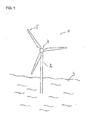
- FIG. 1 shows a simplified wind power plant 1 according to an embodiment of the invention.
- the wind power plant 1 comprises a supporting structure 2, which is based on a suitable foundation in the sea 3.
- the wind power plant 1 is an offshore wind generator.
- the rotor hub 4 carries a plurality of rotor blades 5.
- a nacelle (not visible) is arranged at the top of the supporting structure 2, which may be for example a tower.
- the tower 2 can comprise an air duct (not visible here) in accordance with the aspects and embodiments of described herein.
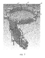
- FIG. 2 is a simplified schematic of an air duct 6 for a wind power plant according to an embodiment.
- the air duct 6 has a circular shape and is composed of segments.
- First segments 11, 12, 13, 14, 15, and 16 are segments comprising air inlets 10 that protrude from the outer circumference of the air duct.
- the first segments 11 to 16 are evenly distributed around the circumference of the air duct 6.
- the first segments 11 to 16 are coupled by second segments 21, 22, 23, 24 and 25.
- Only first segments 14 and 15 are coupled by a third segment 31 which comprises an air vent 7.
- the air duct 6 is a separate component that can be mounted to a supporting structure (for example a tower) of a wind power plant.
- the air duct 6 is not integrated into the wall of the supporting structure of the wind power plant.
- the air duct 6 comprises six segments of a first type (first segments 11 to 16), five segments of a second type (second segments 21 to 25) and one segment 31 of a third type. Accordingly, there is a first set of first segments 11 to 16, a second set of second segments 21 to 25 and third set comprising a single third segment 31. Using similar or identical segments simplifies production and reduces production costs.
- FIG. 3 is a simplified perspective view on an air duct 6 for a wind power plant according to an embodiment.
- the air duct 6 is basically similar to the one shown in FIG. 2 .
- the air duct 6 is configured to be fixed horizontally in the supporting structure (tower) of a wind power plant.
- the air guiding member 8 extends downwardly and inside the supporting structure of a wind power plant.
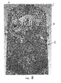
- FIG. 4 is a simplified perspective on the air duct 6 shown in FIG. 3 mounted in a supporting structure, here a tower 2 of a wind power plant.
- the air duct 6 is oriented horizontally and located inside the wall 9 of the tower 2.
- the air duct 6 extends along the inner side (along the circumference) of the wall 9 of the wind power plant.
- the noses 10 of the air duct 6 protrude from outwardly from the air duct 6 and extend through the wall 9 of the tower 2.
- the air guiding member 8 extends downwardly into the tower 2. It is apparent that the air duct 6 is not integrated into the wall 9 of the tower 2. This allows retrofitting the wind power plant with an air duct 6 and generally simplifies assembly of the wind power plant. Manufacturing of the air duct 6 and mounting the air duct 6 to the tower 2 is particularly simplified if the air duct 6 is composed of segments, in particular a plurality of similar or identical segments.
- the air duct 6 is supported by braces 41 which are fixed to the inner side of the wall 9 of the wind power plant.
- the braces 41 can be more or less evenly distributed along the air duct 6.
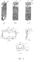
- FIGs 5A to 5F are simplified schematics of details of an air duct 6 according to an embodiment.
- FIG. 5A shows an end of a segment 51, either a first segment, a second segment or a third segment, of the air duct 6.
- the end has a flange 53.
- FIG. 5B shows the flanged ends of two adjacent segments 51, 52, which are, for example first and second segments or first and third segments.
- the two segments 51, 52 are coupled flush together.
- the flanges of two adjacent segments 51, 52 lie against each other.
- FIG. 5C shows a securing member 54 which encompasses the outer circumference and thereby the flush flanges of the two adjacent segments 51, 52.
- the securing member 54 holds the adjacent segments 51, 52 of the air duct 6 together.
- FIG. 5D shows a cross-section of segments 51, 52 through the securing member 54 shown in FIG. 5D .
- Each of the segments can be a first segment, a second segment or a third segment.
- the cross section of the segments has to V-shaped portions 55, 56 on opposite sides.
- FIG. 5E shows one of the locks 57, 58 shown in FIG. 5D .
- the lock comprises a tensioning screw for increasing the tension of the securing member 54.
- FIG. 5F shows a cross sectional view of the profile of the securing member 54.
- the cross-sectional shape of the securing member is designed to press the flanges of two adjacent segments together and against a gasket (as shown in FIG. 5G ).
- the securing member 54 basically comprises two parts. One flat part 54-1 and another trapezoidal part having two flanges 54-2 and 54-3 extending from the flat part 54-1.
- the flanges 54-2 and 54-3 extend outwardly in order to provide a higher pressure once the securing element 54 is placed and tightened around the end flanges of two adjacent segments 51, 52.
- the angle between the flanges 54-2 and 54-3 is about 40°.
- FIG. 5G shows the cross sectional view of FIG. 5F and the gasket 59.
- This gasket 59 is made of an elastic material (for example foam or rubber) in order to add a resilient member between the flanges of the adjacent segments 51, 52 to allow tightening of the construction with the securing member 54 which has a trapezoidal shape for the purpose of tightening.
- the securing member 54 basically comprises two parts. One flat part 54-1 and another trapezoidal part having two flanges 54-2 and 54-3 extending with a relative angle of 40° from the flat part 54-1. The flanges 54-2 and 54-3 are bent outwardly in order to provide a higher pressure once the securing element 54 is placed and tightened around the end flanges of two adjacent segments 51, 52.
- FIG. 6A and 6B are simplified schematics of a supporting arrangement for the air duct 6 according to an embodiment.
- Each of the supporting braces 41 has an upper strut 61, a lower strut 63 and a central strut 62 connecting the upper strut 61 and the lower strut 63.
- the upper strut 61 and the lower strut 63 extend from the inner wall of the tower of the wind power plant over the air duct 6, here segments 25 and 11.
- the central strut 62 extends vertically along the inner side of the wall of the wind power plant. Screws 64 or bolts can be used to fix the brace 41 to the inner side of the wall of a tower of a wind power plant.
- first opening 67-1 in the upper strut 61 There is a first opening 67-1 in the upper strut 61, a second opening 67-2 in the upper strut 61 and a first opening 67-3 in the lower strut 63 and a second opening 67-4 in the lower strut 63.
- a belt or the like (not shown here) can extend through the first opening 67-1 in the upper strut 61 then encompass the lower side of the air duct 6 segment, extend through the second opening 67-2 in the upper strut 61 then run to a first opening 67-3 in the lower strut 63 encompass the upper side of the air duct 6 segment and then run through the second opening 67-4 in the lower strut 63 in order to secure the air duct to the supporting braces 41.
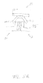
- FIG. 6B shows a simplified schematic of a suspension of the air duct 6 within a brace 41.
- a belt 65 can be wound around the air duct 6 and through openings 67 in the brace 41, in particular through openings 67 in the upper strut 61 and the lower strut 63 of the brace 41.
- the belt 65 can extend through a first opening 67-1 in the upper strut 61 then encompass the lower side of the air duct 6 segment, extend through the second opening 67-2 in the upper strut 61 then run to a first opening 67-3 in the lower strut 63 encompass the upper side of the air duct 6 segment and then run through the second opening 67-4 in the lower strut 63.
- a locking device 67 may be used to couple and secure the ends of the belt.
- This kind of suspension using braces 41 and belts 65 can be used along the air duct 6 and might be evenly distributed and/or in accordance with the load distribution. This provides a resilient but stable suspension of the air duct 6.
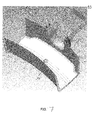
- FIG. 7 is a simplified schematic of a detail of a sealing 71 for a first segment 11 of the air duct 6 according to an embodiment.
- the sealing 71 encompasses the inlet portion 10 of segment 11 and resides between the inner side of the wall of the tower of the wind power plant and the air duct 6. This provides a tight and robust protection against water etc.
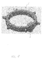
- FIG. 8 is a simplified perspective view on an air duct 6 for a wind power plant according to an embodiment.
- the third segment 31 (substantially as previously described) can be configured such that it accommodates at least one water drop separator or air conditioner (not shown).
- the third segment 31 may then have two symmetrical sections 31-1 and 31-2 on opposite sides of the connection to the substantially vertical tubular air guiding structure (air guiding member 8). Each of the two sections 31-1 and 31-2 of the third segment 31 may then accommodate one water drop separator or air conditioner.
- the air duct 6 may also be coupled to braces 41 by chains 81 or the like instead of belts.
- the chains 81 may then directly be coupled to the segments of the air duct 6 by hooks or other fixing means.
- the third segment 31 of this embodiment is shown in more detail in FIG. 9 .
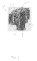
- FIG. 9 is a simplified perspective view on a third segment 31 for an air duct 6 for a wind power plant according to the embodiment shown in FIG. 8 .
- the third segment 31 comprises two symmetrical sections 31-1 and 31-2 on opposite sides of the connection to the substantially vertical tubular air guiding structure (air guiding member 8).
- Each of the two sections 31-1 and 31-2 of the third segment 31 may then accommodate one water drop separator or air conditioner 91, 92. This configuration removes water and/or aerosols from the air before the air is passed to the air guiding member 8.
- the segments (first, second, third etc) of the air duct are coupled such that they are in fluidic communication with each other and other air guiding components (for example air guiding structure 8) such that the air can pass through the segments and to the air guiding structure 8.
- the air duct may be assembled within the tower of the wind power plant.
Landscapes
- Engineering & Computer Science (AREA)
- Life Sciences & Earth Sciences (AREA)
- Sustainable Development (AREA)
- Sustainable Energy (AREA)
- Chemical & Material Sciences (AREA)
- Combustion & Propulsion (AREA)
- Mechanical Engineering (AREA)
- General Engineering & Computer Science (AREA)
- Physics & Mathematics (AREA)
- Thermal Sciences (AREA)
- Wind Motors (AREA)
Priority Applications (9)
| Application Number | Priority Date | Filing Date | Title |
|---|---|---|---|
| EP14164790.9A EP2933481B1 (fr) | 2014-04-15 | 2014-04-15 | Conduit d'air pour éolienne, éolienne, procédé de fabrication d'un conduit d'air et procédé de modernisation d'une installation éolienne avec un conduit d'air |
| DK14164790.9T DK2933481T3 (en) | 2014-04-15 | 2014-04-15 | Air duct for wind turbines, wind turbines, method for producing an air duct and method for upgrading a wind turbine with an air duct |
| BR112016024076-6A BR112016024076B1 (pt) | 2014-04-15 | 2015-04-15 | Duto de ar para uma usina de energia eólica, usina de energia eólica, método de fabricação de um duto de ar para uma usina de energia eólica e método para remontagem de uma usina de energia eólica com um duto de ar |
| CA2945549A CA2945549C (fr) | 2014-04-15 | 2015-04-15 | Conduit d'air destine a une installation eolienne |
| PCT/EP2015/058199 WO2015158788A1 (fr) | 2014-04-15 | 2015-04-15 | Conduit d'air pour centrale éolienne, centrale éolienne, procédé de fabrication d'un conduit d'air et procédé de rattrapage d'une centrale éolienne avec un conduit d'air |
| CN201580020151.6A CN106795865B (zh) | 2014-04-15 | 2015-04-15 | 用于风力发电站的风道、风力发电站、制造风道的方法以及利用风道改造风力发电站的方法 |
| US15/303,233 US10539121B2 (en) | 2014-04-15 | 2015-04-15 | Wind power plant air duct and method of manufacturing the same |
| JP2016562888A JP2017511441A (ja) | 2014-04-15 | 2015-04-15 | 風力発電プラント用エアダクト、風力発電プラント、エアダクトを製造する方法、及び風力発電プラントにエアダクトを後付けする方法 |
| KR1020167031914A KR20160148588A (ko) | 2014-04-15 | 2015-04-15 | 풍력 발전소용 에어 덕트, 풍력 발전소, 에어 덕트의 제조방법 및 에어 덕트로 풍력 발전소를 개조하는 방법 |
Applications Claiming Priority (1)
| Application Number | Priority Date | Filing Date | Title |
|---|---|---|---|
| EP14164790.9A EP2933481B1 (fr) | 2014-04-15 | 2014-04-15 | Conduit d'air pour éolienne, éolienne, procédé de fabrication d'un conduit d'air et procédé de modernisation d'une installation éolienne avec un conduit d'air |
Publications (2)
| Publication Number | Publication Date |
|---|---|
| EP2933481A1 true EP2933481A1 (fr) | 2015-10-21 |
| EP2933481B1 EP2933481B1 (fr) | 2019-01-09 |
Family
ID=50486804
Family Applications (1)
| Application Number | Title | Priority Date | Filing Date |
|---|---|---|---|
| EP14164790.9A Not-in-force EP2933481B1 (fr) | 2014-04-15 | 2014-04-15 | Conduit d'air pour éolienne, éolienne, procédé de fabrication d'un conduit d'air et procédé de modernisation d'une installation éolienne avec un conduit d'air |
Country Status (9)
| Country | Link |
|---|---|
| US (1) | US10539121B2 (fr) |
| EP (1) | EP2933481B1 (fr) |
| JP (1) | JP2017511441A (fr) |
| KR (1) | KR20160148588A (fr) |
| CN (1) | CN106795865B (fr) |
| BR (1) | BR112016024076B1 (fr) |
| CA (1) | CA2945549C (fr) |
| DK (1) | DK2933481T3 (fr) |
| WO (1) | WO2015158788A1 (fr) |
Families Citing this family (2)
| Publication number | Priority date | Publication date | Assignee | Title |
|---|---|---|---|---|
| BR112020010500A2 (pt) | 2017-11-27 | 2020-11-10 | Telefonaktiebolaget Lm Ericsson (Publ) | método de alocação de recurso de rádio, dispositivo de rádio, primeiro dispositivo de rádio, sistema de comunicação, método implementado em um sistema de comunicação, e, equipamento de usuário |
| KR102125134B1 (ko) | 2018-08-13 | 2020-06-22 | 김하영 | 풍력 발전기용 유도 덕트 및 이를 가진 풍력 발전기 |
Citations (7)
| Publication number | Priority date | Publication date | Assignee | Title |
|---|---|---|---|---|
| WO2001006121A1 (fr) * | 1999-07-14 | 2001-01-25 | Aloys Wobben | Eolienne a circuit de refroidissement ferme |
| EP2187047A2 (fr) * | 2008-11-12 | 2010-05-19 | Wilic S.Àr.L. | Éolienne |
| WO2010069954A1 (fr) | 2008-12-17 | 2010-06-24 | Xemc Darwind Bv | Éolienne comprenant un circuit de refroidissement |
| EP2453451A2 (fr) * | 2010-11-12 | 2012-05-16 | Hitachi Industrial Equipment Systems Co., Ltd. | Transformateur pour station d'énergie éolienne et/ou installations de génération d'énergie éolienne installés avec le transformateur pour station d'énergie éolienne |
| EP2503144A1 (fr) * | 2009-11-18 | 2012-09-26 | Juen Soo Kim | Tour de collecte de vent pour un générateur d'énergie éolienne |
| US20120266995A1 (en) * | 2011-04-22 | 2012-10-25 | JTB Steel Industries Inc. | Method and apparatus for suspending duct by inserted corner members |
| EP2568170A1 (fr) | 2011-09-09 | 2013-03-13 | Areva Wind GmbH | Tour d'éolienne dotée d'un renfort de paroi de tour guidant l'air circonférentiel |
Family Cites Families (4)
| Publication number | Priority date | Publication date | Assignee | Title |
|---|---|---|---|---|
| DE102008012664A1 (de) * | 2008-01-30 | 2009-08-06 | Repower Systems Ag | Windenergieanlage und ein Turm oder Turmsegment und eine Türzarge dafür |
| US20090223163A1 (en) * | 2008-03-10 | 2009-09-10 | Shu Ching Quek | Wind Turbine Tower Including An Induction Brazed Joint And A Method Of Fabricating The Wind Turbine Tower |
| PL2151833T3 (pl) * | 2008-08-07 | 2013-08-30 | Starkstrom Geraetebau Gmbh | Układ transformatorowy |
| US20130296085A1 (en) * | 2010-11-03 | 2013-11-07 | Pete Parenti | Flexible hole ball with angled hole walls |
-
2014
- 2014-04-15 DK DK14164790.9T patent/DK2933481T3/en active
- 2014-04-15 EP EP14164790.9A patent/EP2933481B1/fr not_active Not-in-force
-
2015
- 2015-04-15 CN CN201580020151.6A patent/CN106795865B/zh not_active Expired - Fee Related
- 2015-04-15 WO PCT/EP2015/058199 patent/WO2015158788A1/fr not_active Ceased
- 2015-04-15 KR KR1020167031914A patent/KR20160148588A/ko not_active Ceased
- 2015-04-15 CA CA2945549A patent/CA2945549C/fr not_active Expired - Fee Related
- 2015-04-15 US US15/303,233 patent/US10539121B2/en not_active Expired - Fee Related
- 2015-04-15 BR BR112016024076-6A patent/BR112016024076B1/pt not_active IP Right Cessation
- 2015-04-15 JP JP2016562888A patent/JP2017511441A/ja active Pending
Patent Citations (7)
| Publication number | Priority date | Publication date | Assignee | Title |
|---|---|---|---|---|
| WO2001006121A1 (fr) * | 1999-07-14 | 2001-01-25 | Aloys Wobben | Eolienne a circuit de refroidissement ferme |
| EP2187047A2 (fr) * | 2008-11-12 | 2010-05-19 | Wilic S.Àr.L. | Éolienne |
| WO2010069954A1 (fr) | 2008-12-17 | 2010-06-24 | Xemc Darwind Bv | Éolienne comprenant un circuit de refroidissement |
| EP2503144A1 (fr) * | 2009-11-18 | 2012-09-26 | Juen Soo Kim | Tour de collecte de vent pour un générateur d'énergie éolienne |
| EP2453451A2 (fr) * | 2010-11-12 | 2012-05-16 | Hitachi Industrial Equipment Systems Co., Ltd. | Transformateur pour station d'énergie éolienne et/ou installations de génération d'énergie éolienne installés avec le transformateur pour station d'énergie éolienne |
| US20120266995A1 (en) * | 2011-04-22 | 2012-10-25 | JTB Steel Industries Inc. | Method and apparatus for suspending duct by inserted corner members |
| EP2568170A1 (fr) | 2011-09-09 | 2013-03-13 | Areva Wind GmbH | Tour d'éolienne dotée d'un renfort de paroi de tour guidant l'air circonférentiel |
Also Published As
| Publication number | Publication date |
|---|---|
| BR112016024076A2 (pt) | 2017-08-15 |
| US10539121B2 (en) | 2020-01-21 |
| EP2933481B1 (fr) | 2019-01-09 |
| JP2017511441A (ja) | 2017-04-20 |
| DK2933481T3 (en) | 2019-04-15 |
| CA2945549C (fr) | 2018-10-09 |
| KR20160148588A (ko) | 2016-12-26 |
| US20170030338A1 (en) | 2017-02-02 |
| BR112016024076B1 (pt) | 2022-09-06 |
| CA2945549A1 (fr) | 2015-10-22 |
| CN106795865A (zh) | 2017-05-31 |
| WO2015158788A1 (fr) | 2015-10-22 |
| CN106795865B (zh) | 2021-07-27 |
Similar Documents
| Publication | Publication Date | Title |
|---|---|---|
| US10487581B2 (en) | Internal ladder assembly for a wind turbine rotor hub | |
| CN110352299B (zh) | 具有液体保留特性的机舱 | |
| US20130236311A1 (en) | Wind turbine with access features for gaining access to the interior of a rotor hub | |
| US11585054B2 (en) | Hatches of nacelle and helicopter hoisting platform | |
| US20170101823A1 (en) | Ladder attachment system for a wind turbine | |
| CA2945549C (fr) | Conduit d'air destine a une installation eolienne | |
| US20190017493A1 (en) | Bulkhead Arrangement for a Wind Turbine Blade | |
| US11754050B2 (en) | Modular tower damper system | |
| US10030663B2 (en) | Method and apparatus for cooling tower fan mounting for removal from inside the tower | |
| CN106164476A (zh) | 风能设备的转子叶片 | |
| WO2015083142A1 (fr) | Éolienne à axe vertical multi-segment | |
| EP2169223A2 (fr) | Chemin de câbles pour une tour d'éolienne | |
| WO2013165926A1 (fr) | Turbines améliorées enfermées dans des conduites et systèmes d'énergie hydroélectrique | |
| KR101348416B1 (ko) | 모듈형 수직축 조류발전기 | |
| WO2018162586A1 (fr) | Configuration intégrée de nez de rotor | |
| CN209228548U (zh) | 一种风电塔筒内底部排水装置 | |
| KR200467545Y1 (ko) | 빗물 유입 방지 장치 | |
| US12168886B2 (en) | Cooling tower fan cylinder | |
| EP3044393A1 (fr) | Procédé et appareil de montage de ventilateur de tour de refroidissement permettant un démontage à partir de l'intérieur de la tour | |
| IT202100029693A1 (it) | Carosello Eolico per produzione energia elettrica | |
| KR20110046041A (ko) | 풍력발전기를 갖는 차량 |
Legal Events
| Date | Code | Title | Description |
|---|---|---|---|
| PUAI | Public reference made under article 153(3) epc to a published international application that has entered the european phase |
Free format text: ORIGINAL CODE: 0009012 |
|
| AK | Designated contracting states |
Kind code of ref document: A1 Designated state(s): AL AT BE BG CH CY CZ DE DK EE ES FI FR GB GR HR HU IE IS IT LI LT LU LV MC MK MT NL NO PL PT RO RS SE SI SK SM TR |
|
| AX | Request for extension of the european patent |
Extension state: BA ME |
|
| 17P | Request for examination filed |
Effective date: 20160420 |
|
| RBV | Designated contracting states (corrected) |
Designated state(s): AL AT BE BG CH CY CZ DE DK EE ES FI FR GB GR HR HU IE IS IT LI LT LU LV MC MK MT NL NO PL PT RO RS SE SI SK SM TR |
|
| STAA | Information on the status of an ep patent application or granted ep patent |
Free format text: STATUS: EXAMINATION IS IN PROGRESS |
|
| 17Q | First examination report despatched |
Effective date: 20170623 |
|
| REG | Reference to a national code |
Ref country code: DE Ref legal event code: R079 Ref document number: 602014039429 Country of ref document: DE Free format text: PREVIOUS MAIN CLASS: F03D0011000000 Ipc: F03D0013200000 |
|
| GRAP | Despatch of communication of intention to grant a patent |
Free format text: ORIGINAL CODE: EPIDOSNIGR1 |
|
| STAA | Information on the status of an ep patent application or granted ep patent |
Free format text: STATUS: GRANT OF PATENT IS INTENDED |
|
| RIC1 | Information provided on ipc code assigned before grant |
Ipc: F03D 80/60 20160101ALI20180723BHEP Ipc: F03D 13/20 20160101AFI20180723BHEP Ipc: F03D 80/80 20160101ALI20180723BHEP |
|
| INTG | Intention to grant announced |
Effective date: 20180813 |
|
| GRAS | Grant fee paid |
Free format text: ORIGINAL CODE: EPIDOSNIGR3 |
|
| GRAA | (expected) grant |
Free format text: ORIGINAL CODE: 0009210 |
|
| STAA | Information on the status of an ep patent application or granted ep patent |
Free format text: STATUS: THE PATENT HAS BEEN GRANTED |
|
| AK | Designated contracting states |
Kind code of ref document: B1 Designated state(s): AL AT BE BG CH CY CZ DE DK EE ES FI FR GB GR HR HU IE IS IT LI LT LU LV MC MK MT NL NO PL PT RO RS SE SI SK SM TR |
|
| REG | Reference to a national code |
Ref country code: GB Ref legal event code: FG4D |
|
| REG | Reference to a national code |
Ref country code: CH Ref legal event code: EP Ref country code: AT Ref legal event code: REF Ref document number: 1087634 Country of ref document: AT Kind code of ref document: T Effective date: 20190115 |
|
| REG | Reference to a national code |
Ref country code: IE Ref legal event code: FG4D |
|
| REG | Reference to a national code |
Ref country code: DE Ref legal event code: R096 Ref document number: 602014039429 Country of ref document: DE |
|
| REG | Reference to a national code |
Ref country code: DK Ref legal event code: T3 Effective date: 20190408 |
|
| RAP2 | Party data changed (patent owner data changed or rights of a patent transferred) |
Owner name: ADWEN GMBH |
|
| REG | Reference to a national code |
Ref country code: NL Ref legal event code: MP Effective date: 20190109 |
|
| REG | Reference to a national code |
Ref country code: LT Ref legal event code: MG4D |
|
| PG25 | Lapsed in a contracting state [announced via postgrant information from national office to epo] |
Ref country code: NL Free format text: LAPSE BECAUSE OF FAILURE TO SUBMIT A TRANSLATION OF THE DESCRIPTION OR TO PAY THE FEE WITHIN THE PRESCRIBED TIME-LIMIT Effective date: 20190109 |
|
| REG | Reference to a national code |
Ref country code: AT Ref legal event code: MK05 Ref document number: 1087634 Country of ref document: AT Kind code of ref document: T Effective date: 20190109 |
|
| PG25 | Lapsed in a contracting state [announced via postgrant information from national office to epo] |
Ref country code: FI Free format text: LAPSE BECAUSE OF FAILURE TO SUBMIT A TRANSLATION OF THE DESCRIPTION OR TO PAY THE FEE WITHIN THE PRESCRIBED TIME-LIMIT Effective date: 20190109 Ref country code: SE Free format text: LAPSE BECAUSE OF FAILURE TO SUBMIT A TRANSLATION OF THE DESCRIPTION OR TO PAY THE FEE WITHIN THE PRESCRIBED TIME-LIMIT Effective date: 20190109 Ref country code: LT Free format text: LAPSE BECAUSE OF FAILURE TO SUBMIT A TRANSLATION OF THE DESCRIPTION OR TO PAY THE FEE WITHIN THE PRESCRIBED TIME-LIMIT Effective date: 20190109 Ref country code: ES Free format text: LAPSE BECAUSE OF FAILURE TO SUBMIT A TRANSLATION OF THE DESCRIPTION OR TO PAY THE FEE WITHIN THE PRESCRIBED TIME-LIMIT Effective date: 20190109 Ref country code: NO Free format text: LAPSE BECAUSE OF FAILURE TO SUBMIT A TRANSLATION OF THE DESCRIPTION OR TO PAY THE FEE WITHIN THE PRESCRIBED TIME-LIMIT Effective date: 20190409 Ref country code: PT Free format text: LAPSE BECAUSE OF FAILURE TO SUBMIT A TRANSLATION OF THE DESCRIPTION OR TO PAY THE FEE WITHIN THE PRESCRIBED TIME-LIMIT Effective date: 20190509 Ref country code: PL Free format text: LAPSE BECAUSE OF FAILURE TO SUBMIT A TRANSLATION OF THE DESCRIPTION OR TO PAY THE FEE WITHIN THE PRESCRIBED TIME-LIMIT Effective date: 20190109 |
|
| PG25 | Lapsed in a contracting state [announced via postgrant information from national office to epo] |
Ref country code: HR Free format text: LAPSE BECAUSE OF FAILURE TO SUBMIT A TRANSLATION OF THE DESCRIPTION OR TO PAY THE FEE WITHIN THE PRESCRIBED TIME-LIMIT Effective date: 20190109 Ref country code: RS Free format text: LAPSE BECAUSE OF FAILURE TO SUBMIT A TRANSLATION OF THE DESCRIPTION OR TO PAY THE FEE WITHIN THE PRESCRIBED TIME-LIMIT Effective date: 20190109 Ref country code: IS Free format text: LAPSE BECAUSE OF FAILURE TO SUBMIT A TRANSLATION OF THE DESCRIPTION OR TO PAY THE FEE WITHIN THE PRESCRIBED TIME-LIMIT Effective date: 20190509 Ref country code: LV Free format text: LAPSE BECAUSE OF FAILURE TO SUBMIT A TRANSLATION OF THE DESCRIPTION OR TO PAY THE FEE WITHIN THE PRESCRIBED TIME-LIMIT Effective date: 20190109 Ref country code: BG Free format text: LAPSE BECAUSE OF FAILURE TO SUBMIT A TRANSLATION OF THE DESCRIPTION OR TO PAY THE FEE WITHIN THE PRESCRIBED TIME-LIMIT Effective date: 20190409 Ref country code: GR Free format text: LAPSE BECAUSE OF FAILURE TO SUBMIT A TRANSLATION OF THE DESCRIPTION OR TO PAY THE FEE WITHIN THE PRESCRIBED TIME-LIMIT Effective date: 20190410 |
|
| REG | Reference to a national code |
Ref country code: DE Ref legal event code: R097 Ref document number: 602014039429 Country of ref document: DE |
|
| PG25 | Lapsed in a contracting state [announced via postgrant information from national office to epo] |
Ref country code: EE Free format text: LAPSE BECAUSE OF FAILURE TO SUBMIT A TRANSLATION OF THE DESCRIPTION OR TO PAY THE FEE WITHIN THE PRESCRIBED TIME-LIMIT Effective date: 20190109 Ref country code: AT Free format text: LAPSE BECAUSE OF FAILURE TO SUBMIT A TRANSLATION OF THE DESCRIPTION OR TO PAY THE FEE WITHIN THE PRESCRIBED TIME-LIMIT Effective date: 20190109 Ref country code: RO Free format text: LAPSE BECAUSE OF FAILURE TO SUBMIT A TRANSLATION OF THE DESCRIPTION OR TO PAY THE FEE WITHIN THE PRESCRIBED TIME-LIMIT Effective date: 20190109 Ref country code: CZ Free format text: LAPSE BECAUSE OF FAILURE TO SUBMIT A TRANSLATION OF THE DESCRIPTION OR TO PAY THE FEE WITHIN THE PRESCRIBED TIME-LIMIT Effective date: 20190109 Ref country code: AL Free format text: LAPSE BECAUSE OF FAILURE TO SUBMIT A TRANSLATION OF THE DESCRIPTION OR TO PAY THE FEE WITHIN THE PRESCRIBED TIME-LIMIT Effective date: 20190109 Ref country code: IT Free format text: LAPSE BECAUSE OF FAILURE TO SUBMIT A TRANSLATION OF THE DESCRIPTION OR TO PAY THE FEE WITHIN THE PRESCRIBED TIME-LIMIT Effective date: 20190109 Ref country code: SK Free format text: LAPSE BECAUSE OF FAILURE TO SUBMIT A TRANSLATION OF THE DESCRIPTION OR TO PAY THE FEE WITHIN THE PRESCRIBED TIME-LIMIT Effective date: 20190109 |
|
| PLBE | No opposition filed within time limit |
Free format text: ORIGINAL CODE: 0009261 |
|
| STAA | Information on the status of an ep patent application or granted ep patent |
Free format text: STATUS: NO OPPOSITION FILED WITHIN TIME LIMIT |
|
| PG25 | Lapsed in a contracting state [announced via postgrant information from national office to epo] |
Ref country code: SM Free format text: LAPSE BECAUSE OF FAILURE TO SUBMIT A TRANSLATION OF THE DESCRIPTION OR TO PAY THE FEE WITHIN THE PRESCRIBED TIME-LIMIT Effective date: 20190109 |
|
| REG | Reference to a national code |
Ref country code: CH Ref legal event code: PL |
|
| 26N | No opposition filed |
Effective date: 20191010 |
|
| REG | Reference to a national code |
Ref country code: BE Ref legal event code: MM Effective date: 20190430 |
|
| PG25 | Lapsed in a contracting state [announced via postgrant information from national office to epo] |
Ref country code: LU Free format text: LAPSE BECAUSE OF NON-PAYMENT OF DUE FEES Effective date: 20190415 Ref country code: MC Free format text: LAPSE BECAUSE OF FAILURE TO SUBMIT A TRANSLATION OF THE DESCRIPTION OR TO PAY THE FEE WITHIN THE PRESCRIBED TIME-LIMIT Effective date: 20190109 |
|
| PG25 | Lapsed in a contracting state [announced via postgrant information from national office to epo] |
Ref country code: CH Free format text: LAPSE BECAUSE OF NON-PAYMENT OF DUE FEES Effective date: 20190430 Ref country code: LI Free format text: LAPSE BECAUSE OF NON-PAYMENT OF DUE FEES Effective date: 20190430 |
|
| PG25 | Lapsed in a contracting state [announced via postgrant information from national office to epo] |
Ref country code: BE Free format text: LAPSE BECAUSE OF NON-PAYMENT OF DUE FEES Effective date: 20190430 Ref country code: FR Free format text: LAPSE BECAUSE OF NON-PAYMENT OF DUE FEES Effective date: 20190430 Ref country code: SI Free format text: LAPSE BECAUSE OF FAILURE TO SUBMIT A TRANSLATION OF THE DESCRIPTION OR TO PAY THE FEE WITHIN THE PRESCRIBED TIME-LIMIT Effective date: 20190109 |
|
| PG25 | Lapsed in a contracting state [announced via postgrant information from national office to epo] |
Ref country code: TR Free format text: LAPSE BECAUSE OF FAILURE TO SUBMIT A TRANSLATION OF THE DESCRIPTION OR TO PAY THE FEE WITHIN THE PRESCRIBED TIME-LIMIT Effective date: 20190109 |
|
| PG25 | Lapsed in a contracting state [announced via postgrant information from national office to epo] |
Ref country code: IE Free format text: LAPSE BECAUSE OF NON-PAYMENT OF DUE FEES Effective date: 20190415 |
|
| REG | Reference to a national code |
Ref country code: DE Ref legal event code: R081 Ref document number: 602014039429 Country of ref document: DE Owner name: SIEMENS GAMESA RENEWABLE ENERGY DEUTSCHLAND GM, DE Free format text: FORMER OWNER: AREVA WIND GMBH, 27572 BREMERHAVEN, DE Ref country code: DE Ref legal event code: R082 Ref document number: 602014039429 Country of ref document: DE Representative=s name: ASPACHER, KARL-GEORG, DE Ref country code: DE Ref legal event code: R081 Ref document number: 602014039429 Country of ref document: DE Owner name: ADWEN GMBH, DE Free format text: FORMER OWNER: AREVA WIND GMBH, 27572 BREMERHAVEN, DE |
|
| PG25 | Lapsed in a contracting state [announced via postgrant information from national office to epo] |
Ref country code: CY Free format text: LAPSE BECAUSE OF FAILURE TO SUBMIT A TRANSLATION OF THE DESCRIPTION OR TO PAY THE FEE WITHIN THE PRESCRIBED TIME-LIMIT Effective date: 20190109 |
|
| PG25 | Lapsed in a contracting state [announced via postgrant information from national office to epo] |
Ref country code: HU Free format text: LAPSE BECAUSE OF FAILURE TO SUBMIT A TRANSLATION OF THE DESCRIPTION OR TO PAY THE FEE WITHIN THE PRESCRIBED TIME-LIMIT; INVALID AB INITIO Effective date: 20140415 Ref country code: MT Free format text: LAPSE BECAUSE OF FAILURE TO SUBMIT A TRANSLATION OF THE DESCRIPTION OR TO PAY THE FEE WITHIN THE PRESCRIBED TIME-LIMIT Effective date: 20190109 |
|
| PGFP | Annual fee paid to national office [announced via postgrant information from national office to epo] |
Ref country code: DK Payment date: 20210422 Year of fee payment: 8 |
|
| REG | Reference to a national code |
Ref country code: DE Ref legal event code: R081 Ref document number: 602014039429 Country of ref document: DE Owner name: SIEMENS GAMESA RENEWABLE ENERGY DEUTSCHLAND GM, DE Free format text: FORMER OWNER: ADWEN GMBH, 27572 BREMERHAVEN, DE |
|
| PG25 | Lapsed in a contracting state [announced via postgrant information from national office to epo] |
Ref country code: MK Free format text: LAPSE BECAUSE OF FAILURE TO SUBMIT A TRANSLATION OF THE DESCRIPTION OR TO PAY THE FEE WITHIN THE PRESCRIBED TIME-LIMIT Effective date: 20190109 |
|
| REG | Reference to a national code |
Ref country code: DE Ref legal event code: R082 Ref document number: 602014039429 Country of ref document: DE Representative=s name: SAUTHOFF, KARSTEN, DIPL.-ING. UNIV., DE |
|
| REG | Reference to a national code |
Ref country code: DK Ref legal event code: EBP Effective date: 20220430 |
|
| PG25 | Lapsed in a contracting state [announced via postgrant information from national office to epo] |
Ref country code: DK Free format text: LAPSE BECAUSE OF NON-PAYMENT OF DUE FEES Effective date: 20220430 |
|
| PGFP | Annual fee paid to national office [announced via postgrant information from national office to epo] |
Ref country code: DE Payment date: 20230418 Year of fee payment: 10 |
|
| PGFP | Annual fee paid to national office [announced via postgrant information from national office to epo] |
Ref country code: GB Payment date: 20230420 Year of fee payment: 10 |
|
| REG | Reference to a national code |
Ref country code: DE Ref legal event code: R119 Ref document number: 602014039429 Country of ref document: DE |
|
| GBPC | Gb: european patent ceased through non-payment of renewal fee |
Effective date: 20240415 |
|
| PG25 | Lapsed in a contracting state [announced via postgrant information from national office to epo] |
Ref country code: DE Free format text: LAPSE BECAUSE OF NON-PAYMENT OF DUE FEES Effective date: 20241105 |
|
| PG25 | Lapsed in a contracting state [announced via postgrant information from national office to epo] |
Ref country code: GB Free format text: LAPSE BECAUSE OF NON-PAYMENT OF DUE FEES Effective date: 20240415 |
|
| PG25 | Lapsed in a contracting state [announced via postgrant information from national office to epo] |
Ref country code: GB Free format text: LAPSE BECAUSE OF NON-PAYMENT OF DUE FEES Effective date: 20240415 Ref country code: DE Free format text: LAPSE BECAUSE OF NON-PAYMENT OF DUE FEES Effective date: 20241105 |