EP2933596B1 - Dispositif de retenue pour un échangeur de chaleur - Google Patents
Dispositif de retenue pour un échangeur de chaleur Download PDFInfo
- Publication number
- EP2933596B1 EP2933596B1 EP15157913.3A EP15157913A EP2933596B1 EP 2933596 B1 EP2933596 B1 EP 2933596B1 EP 15157913 A EP15157913 A EP 15157913A EP 2933596 B1 EP2933596 B1 EP 2933596B1
- Authority
- EP
- European Patent Office
- Prior art keywords
- retention device
- guide
- core
- product
- tubes
- Prior art date
- Legal status (The legal status is an assumption and is not a legal conclusion. Google has not performed a legal analysis and makes no representation as to the accuracy of the status listed.)
- Not-in-force
Links
- 230000014759 maintenance of location Effects 0.000 title claims description 111
- 239000007789 gas Substances 0.000 description 29
- 239000012809 cooling fluid Substances 0.000 description 15
- 238000002485 combustion reaction Methods 0.000 description 6
- 229910052751 metal Inorganic materials 0.000 description 5
- 239000002184 metal Substances 0.000 description 5
- 238000005219 brazing Methods 0.000 description 4
- 230000000694 effects Effects 0.000 description 4
- 239000012530 fluid Substances 0.000 description 4
- 230000013011 mating Effects 0.000 description 4
- 239000000463 material Substances 0.000 description 3
- 230000000717 retained effect Effects 0.000 description 3
- 230000007704 transition Effects 0.000 description 3
- IJGRMHOSHXDMSA-UHFFFAOYSA-N Atomic nitrogen Chemical compound N#N IJGRMHOSHXDMSA-UHFFFAOYSA-N 0.000 description 2
- 229910052782 aluminium Inorganic materials 0.000 description 2
- XAGFODPZIPBFFR-UHFFFAOYSA-N aluminium Chemical compound [Al] XAGFODPZIPBFFR-UHFFFAOYSA-N 0.000 description 2
- 230000008901 benefit Effects 0.000 description 2
- 230000015572 biosynthetic process Effects 0.000 description 2
- 238000001816 cooling Methods 0.000 description 2
- 239000000446 fuel Substances 0.000 description 2
- 239000000203 mixture Substances 0.000 description 2
- 229910001220 stainless steel Inorganic materials 0.000 description 2
- 239000010935 stainless steel Substances 0.000 description 2
- 230000001419 dependent effect Effects 0.000 description 1
- 238000003780 insertion Methods 0.000 description 1
- 230000037431 insertion Effects 0.000 description 1
- 238000009434 installation Methods 0.000 description 1
- 238000004519 manufacturing process Methods 0.000 description 1
- 229910052757 nitrogen Inorganic materials 0.000 description 1
- 239000013618 particulate matter Substances 0.000 description 1
- 238000007789 sealing Methods 0.000 description 1
- 230000035939 shock Effects 0.000 description 1
- 238000005476 soldering Methods 0.000 description 1
- 238000005496 tempering Methods 0.000 description 1
Images


Classifications
-
- F—MECHANICAL ENGINEERING; LIGHTING; HEATING; WEAPONS; BLASTING
- F28—HEAT EXCHANGE IN GENERAL
- F28D—HEAT-EXCHANGE APPARATUS, NOT PROVIDED FOR IN ANOTHER SUBCLASS, IN WHICH THE HEAT-EXCHANGE MEDIA DO NOT COME INTO DIRECT CONTACT
- F28D7/00—Heat-exchange apparatus having stationary tubular conduit assemblies for both heat-exchange media, the media being in contact with different sides of a conduit wall
- F28D7/16—Heat-exchange apparatus having stationary tubular conduit assemblies for both heat-exchange media, the media being in contact with different sides of a conduit wall the conduits being arranged in parallel spaced relation
- F28D7/1684—Heat-exchange apparatus having stationary tubular conduit assemblies for both heat-exchange media, the media being in contact with different sides of a conduit wall the conduits being arranged in parallel spaced relation the conduits having a non-circular cross-section
-
- F—MECHANICAL ENGINEERING; LIGHTING; HEATING; WEAPONS; BLASTING
- F28—HEAT EXCHANGE IN GENERAL
- F28F—DETAILS OF HEAT-EXCHANGE AND HEAT-TRANSFER APPARATUS, OF GENERAL APPLICATION
- F28F9/00—Casings; Header boxes; Auxiliary supports for elements; Auxiliary members within casings
- F28F9/005—Other auxiliary members within casings, e.g. internal filling means or sealing means
-
- F—MECHANICAL ENGINEERING; LIGHTING; HEATING; WEAPONS; BLASTING
- F28—HEAT EXCHANGE IN GENERAL
- F28F—DETAILS OF HEAT-EXCHANGE AND HEAT-TRANSFER APPARATUS, OF GENERAL APPLICATION
- F28F9/00—Casings; Header boxes; Auxiliary supports for elements; Auxiliary members within casings
- F28F9/007—Auxiliary supports for elements
- F28F9/013—Auxiliary supports for elements for tubes or tube-assemblies
- F28F9/0133—Auxiliary supports for elements for tubes or tube-assemblies formed by concentric strips
-
- F—MECHANICAL ENGINEERING; LIGHTING; HEATING; WEAPONS; BLASTING
- F28—HEAT EXCHANGE IN GENERAL
- F28F—DETAILS OF HEAT-EXCHANGE AND HEAT-TRANSFER APPARATUS, OF GENERAL APPLICATION
- F28F9/00—Casings; Header boxes; Auxiliary supports for elements; Auxiliary members within casings
- F28F9/26—Arrangements for connecting different sections of heat-exchange elements, e.g. of radiators
-
- F—MECHANICAL ENGINEERING; LIGHTING; HEATING; WEAPONS; BLASTING
- F28—HEAT EXCHANGE IN GENERAL
- F28D—HEAT-EXCHANGE APPARATUS, NOT PROVIDED FOR IN ANOTHER SUBCLASS, IN WHICH THE HEAT-EXCHANGE MEDIA DO NOT COME INTO DIRECT CONTACT
- F28D7/00—Heat-exchange apparatus having stationary tubular conduit assemblies for both heat-exchange media, the media being in contact with different sides of a conduit wall
- F28D7/16—Heat-exchange apparatus having stationary tubular conduit assemblies for both heat-exchange media, the media being in contact with different sides of a conduit wall the conduits being arranged in parallel spaced relation
-
- F—MECHANICAL ENGINEERING; LIGHTING; HEATING; WEAPONS; BLASTING
- F28—HEAT EXCHANGE IN GENERAL
- F28F—DETAILS OF HEAT-EXCHANGE AND HEAT-TRANSFER APPARATUS, OF GENERAL APPLICATION
- F28F9/00—Casings; Header boxes; Auxiliary supports for elements; Auxiliary members within casings
- F28F9/007—Auxiliary supports for elements
- F28F9/013—Auxiliary supports for elements for tubes or tube-assemblies
- F28F9/0131—Auxiliary supports for elements for tubes or tube-assemblies formed by plates
-
- F—MECHANICAL ENGINEERING; LIGHTING; HEATING; WEAPONS; BLASTING
- F28—HEAT EXCHANGE IN GENERAL
- F28F—DETAILS OF HEAT-EXCHANGE AND HEAT-TRANSFER APPARATUS, OF GENERAL APPLICATION
- F28F9/00—Casings; Header boxes; Auxiliary supports for elements; Auxiliary members within casings
- F28F9/007—Auxiliary supports for elements
- F28F9/013—Auxiliary supports for elements for tubes or tube-assemblies
- F28F9/0132—Auxiliary supports for elements for tubes or tube-assemblies formed by slats, tie-rods, articulated or expandable rods
-
- Y—GENERAL TAGGING OF NEW TECHNOLOGICAL DEVELOPMENTS; GENERAL TAGGING OF CROSS-SECTIONAL TECHNOLOGIES SPANNING OVER SEVERAL SECTIONS OF THE IPC; TECHNICAL SUBJECTS COVERED BY FORMER USPC CROSS-REFERENCE ART COLLECTIONS [XRACs] AND DIGESTS
- Y10—TECHNICAL SUBJECTS COVERED BY FORMER USPC
- Y10T—TECHNICAL SUBJECTS COVERED BY FORMER US CLASSIFICATION
- Y10T24/00—Buckles, buttons, clasps, etc.
- Y10T24/45—Separable-fastener or required component thereof [e.g., projection and cavity to complete interlock]
- Y10T24/45225—Separable-fastener or required component thereof [e.g., projection and cavity to complete interlock] including member having distinct formations and mating member selectively interlocking therewith
- Y10T24/45471—Projection having movable connection between components thereof or variable configuration
- Y10T24/45524—Projection having movable connection between components thereof or variable configuration including resiliently biased projection component or surface segment
- Y10T24/45529—Requiring manual force applied against bias to interlock or disengage
Definitions
- the field to which the disclosure generally relates to includes retention device.
- Retention devices may be used in a variety of applications.
- Document EP 2 522 941 A1 which is considered as the closest prior art, discloses a device for reducing vibrations of a tube core of a heat exchanger inside a shell. The device allows a secure and quick insertion after the core has been manufactured and yields that high temperatures - to which the core is subjected for the attachment by means of brazing - do not affect the properties of the device, particularly the elasticity achieved by means of tempering. It is an object underlying the present invention to provide products with a retention device having an improved retention reliability and easy handling.
- a product according to independent claim1 and alternatively by a product according to independent claim 7.
- Preferred embodiments are defined in the respective dependent claims.
- a number of variations may include a product comprising a retention device comprising a plurality of members, including an arch member and a spring member defining multiple contact points.
- Oxides of Nitrogen (NOx) and particulate matter are two components of the engine exhaust emissions that must be controlled.
- EGR exhaust gas recirculation
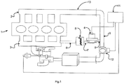
- the engine 1 may have an intake manifold 2 and an exhaust Manifold 3.
- the EGR system may include an exhaust gas recirculation (EGR) valve 4 that controls the flow of exhaust gas to intake manifold 2.
- the heat exchanger 5 may be used to reduce the temperature of the exhaust gas.
- Conduits 6, 7, 8, 9 and 10 may provide the interconnection between the exhaust manifold 3, heat exchanger 5, EGR Valve 4, and Intake manifold 2.
- the system shown may use an electrically controlled EGR valve.
- An electronic control unit (ECU) 11 may provide a signal that will control the opening/closing of the valve. As the EGR valve opens and closes it will increase or decrease the flow rate of exhaust gas to the intake manifold.
- a throttle valve 12 may be provided to control airflow into the intake manifold.
- a portion of the exhaust gas may be recirculated back to the intake manifold where it will be combined with incoming air and fuel.
- the exhaust gas portion of the mixture does not support combustion and when this mixture is compressed and ignited in the cylinder, the inert exhaust gas will control the combustion temperature and limit the formation of NOx and particulate in the exhaust.
- the temperature of the recirculated exhaust gas may be a factor that determines the effectiveness of the NOx and particulate reduction. It is common for an EGR system to include a heat exchanger to remove heat from the exhaust gas and provide an optimize exhaust gas temperature for controlling emissions.
- FIG. 2 One type of heat exchanger 13 is shown in Figures 2, 3 , and 4 . It may include a number of tubes 15 in a rectangular array 16. Tube 15 may have an inner surface 29, wall 30, and outer surface 25, as shown in Figures 3, 3A View A and 4. This rectangular array 16 may also be referred to as the core and exchanger 13 may include one or more cores.
- the tubes 15 may be made of a metal such as stainless steel, aluminum or other suitable material.
- the core 16 may include metal headers 17 and 18 located at either end of the tubes 15.
- the headers 17 and 18 may also be made of a metal such as stainless steel, aluminum or other suitable material.
- the tubes 15 may be secured and sealed to metal headers 17 and 18 by brazing, soldering, or other suitable means.
- the core 16 may be placed in a housing 14 and may be sealed into the housing by a gasket 19, O-ring 20 or other suitable means. At one end, header 18 may be attached to a cone 21 to transition to the O-ring seal 20. Housing 14, core 16, cone 21, gasket 19, and O-ring 20 may define a sealed space 22 within the housing 14. Sealed space 22 may be suitable for introducing a cooling fluid 24 that may contact tubes 15 in the rectangular array 16. Header 17 and gasket 19 may have a first opening 23 to allow a cooling fluid 24 to flow into sealed space 22. Cooling fluid 24 may contact the outer surface 25 of tubes 15. Header 17 and gasket 19 may also have a second opening 26 that may allow cooling fluid 24 to exit sealed space 22.
- a fluid or gas 27 may enter tubes 15 from a first end 28.
- the fluid or gas 27 may be exhaust gas from an internal combustion engine.
- the exhaust gas 27 may be at a first temperature, for example 600°C.
- Exhaust gas 27 may flow through tubes 15 and may exit at a second end 29.
- Cooling fluid 24 may enter sealed space 22 and may contact the outer surface 25 of tubes 15 as shown in Figure 3 . Cooling fluid 24 may be at a lower temperature than exhaust gas 27, for example 100°C.
- the first effect may be the exhaust gas 27 exiting tubes 15 at second end 29 may be at a lower temperature than the exhaust gas 27 entering tubes 15 at the first end 28.
- exhaust gas 27 entering tubes 15, at first end 28, may be at 600°C and the exhaust gas 27 exiting tubes 15, at second end 29, may be at 200°C.
- the reduction in temperature may, in part, be due to the transfer of heat from exhaust gas 27, to tubes 15, and to cooling fluid 24 in sealed space 22.
- the second effect may be the cooling fluid 24 exiting sealed space 22 at second opening 26 may be at a higher temperature than the cooling fluid 24 entering sealed space 22 at the first opening 23.
- the cooling fluid 24 exiting sealed space 22, at second opening 26, may be at 110°C and the cooling fluid 24 entering sealed space 22, at first opening 23 may be at 100°C.
- the increase in temperature may, in part, be due to the transfer of heat from exhaust gas 27, to tubes 15, and to cooling fluid 24 in sealed space 22.
- Both first and second effects may be influenced in-part by parameters such as; the temperature of exhaust gas 27 entering tubes 15, the flow rate of exhaust gas 27, the materials of tubes 15, the wall thickness of tube 15, the length of tube 15, the surface area of tube 15, the fluid properties of the cooling fluid 24 in sealed space 22, the flow rate of the cooling fluid 24 in sealed space 22, or other parameters.
- a baffle 31 shown in figures 4 and 5 may be located along the length of tubes15.
- the baffle 31 may be a metal plate with multiple openings 32 that will receive and support tubes 15. Baffle 31 may add support but it may not be sufficient with high levels of vibration that may cause movement of the tubes 15 and the potential for fatigue of the tubes, the brazing joints, or other components.
- FIG. 6 shows a partial assembly of heat exchanger 13 with a retention device 33 installed on core 16.
- Retention device 33 includes at least one spring member 34.
- Figure 7 shows a portion of retention device 33 and spring member 34 viewed in the direction of arrow 44.
- Retention device 33 includes a first arch member 35 and a second member 36 extending from a first end 37 of first arch member 35. There may be a radius 38 at the transition between first arch member 35 and second member 36 that may define a first contact point 39.
- There may be a third member 40 extending from a second end 41 of first arch member 35.
- Spring member 34 may extend from third member 40 and may define a third contact point 45 along the length of spring member 34. Spring member 34 may include a curved section 46 which may include the third contact point 45 as shown in Figure 7 .
- retention device 33 may function in the following manner.
- spring member 34 may deflect in direction 49 and transmit a force to the substantially rigid surface at first contact point 39 and second contact point 43.
- first arch member 35 will remain substantially in the form of the arch and only the first contact point 39 and second contact point 43 will substantially contact rigid surface 47.
- the arch form of first arch member 35 and the minimum contact with rigid surface 47 may allow a less impeded movement of the retention device 33 along substantially rigid surface 47.
- the deflection of spring member 34, in direction 49 is shown as dashed line form 34A, in figure 7 .
- spring member 34 may extend along an axis 50 for a length 51.
- the length 51 may be 5mm, 10mm, or other suitable length to achieve the desired retention requirements.
- There may be an interrupted length 52 along axis 50 followed by a second spring member 34B having a length 53 along axis 50.
- Second spring member 34B may have the same length as first spring member 34 or it may have another length to achieve the desired retention requirements.
- the spring retention device 33 may be manufactured in many shapes to fit the shape of a core. For example it may be manufactured in rectangular shape to fit a rectangular core, a circular shape to fit a circular core, or other shape to suitably fit a core.
- FIG 9 shows retention device 33 installed on rectangular core 16 of heat exchanger 13.
- Retention device 33 has been formed in a rectangular shape to fit the shape of core 16.
- the retention device 33 may be attached and retained to core 16 by interconnecting features 54 which may include a receptacle 55 and an engagement member 56 as seen in Figure 10 View B and Figure 11 .
- interconnecting features 54 may include a receptacle 55 and an engagement member 56 as seen in Figure 10 View B and Figure 11 .
- engagement member 56 engages receptacle 55
- retention device 33 will define a closed form or loop and may be retained to core 16 as shown in Figure 9 .
- FIG 12, Figure 13 View C, and Figure 14 view D show retention device 33 installed on core 16.
- Retention device 33 may be assembled to core 16 prior to installing core 16 into housing 14. Core 16 along with retention devices 33 may be slid into housing 14 until core 16 comes into sealing contact with housing 14. Retention device 33 may engage housing 14 within space 22.
- a distance 57, between tubes 15 and an inside wall 58 of housing 14 may be less than a distance 59 between contact points 39, 43, and 45 on spring member 34 of retention device 33. It may be noted that distance 57 may be similar for each of the four inside walls of housing 14 that confront tubes 15 of core 16.
- dimension 57 may be less than dimension 59, there may be an interference dimension 60 that that is substantially the difference between dimension 59 and dimension 57.
- the interference dimension 60 may be substantially 1 mm when dimension 59 is 7mm and dimension 57 is 6mm. Dimension 60 may vary with the tolerance of the components.
- interference dimension 60 may be 1 mm, 2mm, or other dimension that will provide the desired level of retention.
- the selection of interference dimension 60 may in-part be based upon the level of vibration, level of mechanical shock, or other relevant parameter.
- the contact with inside wall 58 and interference 60 may provide a force 73 on third contact point 45 and deflect spring member 34 in direction 62.
- Force 73 may cause first contact point 39 and second contact point 43, of retention device 33, to contact tubes 15 and transmit a force to the tubes.
- Tubes 15 may form a substantially rigid surface, for first contact point 39 and second contact point 43.
- force 73 is applied to the third contact point 45 and spring member 34 deflects in direction 62, first arch member 35 will substantially remain in the form of the arch and only the first contact point 39 and second contact point 43 may substantially contact tubes 15.
- the deflected position 34A of spring member 34, in direction 62 is shown as a solid line in figures 14 View D.
- the initial position of spring member 34 is shown as dashed lines.
- the arched form of first arch member 35 and the minimum contact with the rigid surface of tubes 15, may allow a less impeded movement of retention device 33 along the surface of tubes 15. It may also be possible that only one of the first or second contact points, 39 or 43, may contact the rigid surface of tubes 15. This may be in-part result from dimensional differences of components, assembly variation, or other factors.
- Retention device 33 may extend along the four sides of the rectangular core 16 and may include additional portions of spring member 34. Retention device 33 may contact four inside surfaces of rectangular housing 14. Additional portions of spring member 34 may provide a force on tubes 15 at each location that may tend to prevent movement of the tubes 15 and core 16 when a force is applied to the heat exchanger 13. The force may be applied in any direction to heat exchanger 13 and may result from an impact, vibration, or other force. Preventing or limiting movement of tubes 15 and core 16 may lessen the potential for fatigue and failure of tube 15, brazing joints, or other component.
- guide feature 61 may include two guide members 62 and 63 formed in retention device 33.
- Guide feature 61 may be designed to receive a guide portion 64 of retention device 33 that may include receptacle 55 or engagement feature 56.
- guide portion 64 may include receptacle 55 as shown in Figures 10 View B and 11.
- Guide feature 61 including guide members 62 and 63, may align guide portion 64, receptacle 55, engagement feature 56, and facilitate engagement thereof as shown in Figures 9 and 10 View B.
- guide feature 61 may include a first guide members 62 and second guide member 63 that may retain guide portion 64 and may prevent disengagement.
- An existing portion of retention device 33 may be used as a guide member.
- guide member 63 may be a portion of the first arch member 35, second member 40, or spring member 34 as shown in figure 11 .
- a guide member may also be formed as a separate portion of retention device 33 such as guide member 62 also shown in Figures 10 View B and 11.
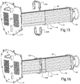
- Installing a one-piece retention device may require deformation to assemble it to the core.
- to efficiently install the retention device it may be made in two pieces as shown in Figure 15 .
- the 2-piece design may include a first retention device 33A and second retention device 33B.
- the 2-piece design will allow installation after assembly of core 16, including tubes 15, header 17, header 18, and baffle 31.
- the retention devices are shown assembled to core 16 in Figure 16 .
- Figure 17 shows first retention device 33A.
- Retention device 33A may have a first member 65, second member 66, and third member 67 formed to fit rectangular core 16. Each of the first, second, and third members may have a spring members 34 spaced along each member.
- Retention device 33A may have interconnecting feature 54 comprising receptacle 55 and engagement member 56 as previously described herein.
- Receptacle 55 may be located at a first end 68 of retention device 33A and engagement member 56 may be located at second end 70.
- Retention device 33A may also include guide feature 61 and guide portion 64 also preciously described herein.
- Guide feature 61 and guide portion 64 may be located at the first or second ends 68 and 70 of retention device 33A.
- guide feature 61 may be located at the second end 70 and guide portion 64 may be located at the first end 68 as shown in figure 17 .
- Guide portion 64 may also include receptacle 55 also shown in figure 17 .
- First retention device 33A and second retention device 33B may be substantially identical in form and may be made from the same manufacturing process. This may reduce cost, reduce tooling requirements, improve assembly, or provide other advantages.
- First retention device 33A and second retention device 33B may be assembled to the core by rotating one of the first or second retention devices 180° about axis 69 and aligning them as shown in figures 18 and 19 .
- Guide feature 61 located at second end 70 of first retention device 33A may align and receive guide portion 64 located at first end 68 of second retention device 33B.
- Guide feature 61 located at second end 70 of second retention device 33B may align and receive guide portion 64 located at first end 68 of first retention device 33A.
- the continued engagement of first and second retention devices 33A and 33B in the direction of arrows 71 and 72 may cause engagement feature 56, of first retention device 33A, to engage receptacle 55 of second retention device 33B. Continued engagement may also cause engagement feature 56 of second retention device 33B to engage receptacle 55 of first retention device 33A.
- retention devices 33A and 33B When engagement members 56 engage receptacles 55, retention devices 33A and 33B will define a closed form or loop as shown in figure 19 . The retention devices 33A and 33B may be retained to core 16 as shown in figure 16 .
- While the afore written description and figures of the invention show a round tube 15 in a rectangular core 16, it may also be within the scope of the invention to be applied to a core having an oval tube, square tube, or a tube of another suitable shape to achieve the desired cooling requirements.
- a core having a shape other than a rectangle may also be utilized.
- the retention device may be applied to a circular core, oval core, or a core of another suitable shape to achieve the desired requirements.
Landscapes
- Engineering & Computer Science (AREA)
- Physics & Mathematics (AREA)
- Thermal Sciences (AREA)
- Mechanical Engineering (AREA)
- General Engineering & Computer Science (AREA)
- Heat-Exchange Devices With Radiators And Conduit Assemblies (AREA)
- Quick-Acting Or Multi-Walled Pipe Joints (AREA)
- Cooling Or The Like Of Electrical Apparatus (AREA)
Claims (11)
- Produit (13) comprenant au moins un dispositif de retenue (33, 33A, 33B), le dispositif de retenue (33, 33A, 33B) comprenant :- un premier élément (35),- un deuxième élément (36) s'étendant d'une première extrémité (37) du premier élément (35) et définissant un premier point de contact (39),- un troisième élément (40) s'étendant de la seconde extrémité (41) du premier élément (35) et définissant un deuxième point de contact (43), et- au moins un élément de ressort (34, 34B) s'étendant depuis au moins un des premier, deuxième ou troisième éléments (35, 36, 40) et définissant un troisième point de contact (45),dans lequel, quand les premier et deuxième points de contact (39, 43) sont en contact avec une surface (47) sensiblement rigide et qu'une force (48) est appliquée au troisième point de contact (45), une force est transmise à la surface (47) sensiblement rigide au niveau du premier et/ou du deuxième point de contact (39, 43) et
caractérisé en ce que le premier élément (35) est conformé comme une arche et est configuré pour rester pratiquement sous la forme de l'arche et ne pas entrer en contact avec la surface (47) sensiblement rigide quand la force (48) est appliquée au troisième point de contact (45). - Produit (13) selon la revendication 1, dans lequel :- ledit dispositif de retenue (33, 33A, 33B) comprend au moins deux éléments de ressort (34, 34B) et- les éléments de ressort (34, 34B) sont espacés l'un de l'autre sur le dispositif de retenue (33, 33A, 33B).
- Produit (13) selon la revendication 1, dans lequel :- ledit dispositif de retenue (33, 33A, 33B) comprend en outre des dispositifs de connexion (54) comprenant un logement (55) et un élément d'enclenchement (56) pour entrer en prise avec ledit logement (55),- le logement (55) et l'élément d'enclenchement (56) sont espacés l'un de l'autre, et- quand l'élément d'enclenchement (56) entre en prise avec le logement (55), le dispositif de retenue (33, 33A, 33B) définit une forme fermée ou boucle pour se fixer à un produit.
- Produit (13) selon la revendication 1 ou 3, dans lequel :- ledit dispositif de retenue (33, 33A, 33B) comprend en outre une caractéristique (61) de guidage et une partie (64) de guide,- ladite caractéristique (61) de guidage comprend au moins un élément (62, 63) de guidage,- ladite partie (64) de guide comprend au moins un des dispositifs de connexion (54), et- l'élément (62, 63) de guidage est structuré et agencé pour guider la partie (64) de guide.
- Produit (13) selon l'une quelconque des revendications 1, 3 et 4, comprenant au moins un second dispositif de retenue (33B ; 33, 33A),
dans lequel lesdits premier et second dispositifs de retenue (33, 33A ; 33B) comprennent en outre :- une caractéristique (61) de guidage sur le premier dispositif de retenue (33, 33A ; 33B) structurée et agencée pour guider une partie (64) de guide sur le second dispositif de retenue (33B ; 33, 33A) et- une caractéristique (61) de guidage sur le second dispositif de retenue (33B ; 33, 33A) structurée et agencée pour guider une partie (64) de guide sur le premier dispositif de retenue (33, 33A ; 33B). - Produit (13) selon la revendication 5, dans lequel la forme de chaque dispositif de retenue (33, 33A, 33B) est sensiblement la même.
- Produit (13), comprenant :- un noyau (16) comprenant une collection de tubes (15),- un logement (14) pour recevoir le noyau (16) et soutenant le noyau (16),- un jeu entre le noyau (16) et le logement (14),et- au moins un dispositif de retenue (33, 33A, 33B) placé entre le logement (14) et le noyau (16),dans lequel ledit dispositif de retenue (33, 33A, 33B) comprend :- un premier élément (35),- un deuxième élément (36) s'étendant d'une première extrémité (37) du premier élément (35) et définissant un premier point de contact (39) le long de l'axe des tubes (15),- un troisième élément (40) s'étendant de la seconde extrémité (41) du premier élément (35) et définissant un deuxième point de contact (43) le long de l'axe des tubes (15), et- au moins un élément de ressort (34, 34B) s'étendant depuis au moins un des premier, deuxième ou troisième éléments (35, 36, 40) et définissant un troisième point de contact (45) avec le logement (14),- quand le jeu entre le logement (14) et le noyau (16) provoque une interférence avec le dispositif de retenue (33, 33A, 33B) et qu'une force (48) est appliquée au troisième point de contact (45) dudit élément de ressort (34, 34B), ledit élément de ressort (34, 34B) est configuré pour transmettre une force au premier et/ou au deuxième point de contact (39, 43) etcaractérisé en ce que le premier élément (35) est conformé comme une arche et configuré pour rester pratiquement sous la forme de l'arche et ne pas entrer en contact le long de l'axe des tubes (15) quand la force (48) est appliquée au troisième point de contact (45).
- Produit (13) selon la revendication 7, dans lequel :- ledit dispositif de retenue (33, 33A, 33B) comprend au moins deux éléments de ressort (34, 34B) et- les éléments de ressort (34, 34B) sont espacés l'un de l'autre sur le dispositif de retenue (33, 33A, 33B).
- Produit (13) selon la revendication 7, dans lequel :- ledit dispositif de retenue (33, 33A, 33B) comprend en outre des dispositifs de connexion (54) comprenant un logement (55) et un élément d'enclenchement (56) pour entrer en prise avec ledit logement (55),- le logement (55) et l'élément d'enclenchement (56) sont espacés l'un de l'autre, et- quand l'élément d'enclenchement (56) entre en prise avec le logement (55), le dispositif de retenue (33, 33A, 33B) définit une forme fermée ou boucle pour se fixer à un produit.
- Produit (13) selon la revendication 7 ou 9, dans lequel :- ledit dispositif de retenue (33, 33A, 33B) comprend en outre une caractéristique (61) de guidage et une partie (64) de guide,- ladite caractéristique (61) de guidage comprend au moins un élément (62, 63) de guidage,- ladite partie (64) de guide comprend au moins un desdits dispositifs de connexion (54), et- l'élément (62, 63) de guidage est structuré et agencé pour guider la partie (64) de guide.
- Produit (13) selon la revendication 7, comprenant au moins un second dispositif de retenue (33B ; 33, 33A),
dans lequel lesdits premier et second dispositifs de retenue (33, 33A ; 33B) comprennent en outre :- une caractéristique (61) de guidage sur le premier dispositif de retenue (33, 33A ; 33B) structurée et agencée pour guider une partie (64) de guide sur le second dispositif de retenue (33B ; 33, 33A) et- une caractéristique (61) de guidage sur le second dispositif de retenue (33B ; 33, 33A) structurée et agencée pour guider une partie (64) de guide sur le premier dispositif de retenue (33, 33A ; 33B).
Applications Claiming Priority (1)
| Application Number | Priority Date | Filing Date | Title |
|---|---|---|---|
| US14/215,740 US20150260465A1 (en) | 2014-03-17 | 2014-03-17 | Retention device for a product |
Publications (2)
| Publication Number | Publication Date |
|---|---|
| EP2933596A1 EP2933596A1 (fr) | 2015-10-21 |
| EP2933596B1 true EP2933596B1 (fr) | 2017-06-14 |
Family
ID=52630245
Family Applications (1)
| Application Number | Title | Priority Date | Filing Date |
|---|---|---|---|
| EP15157913.3A Not-in-force EP2933596B1 (fr) | 2014-03-17 | 2015-03-06 | Dispositif de retenue pour un échangeur de chaleur |
Country Status (4)
| Country | Link |
|---|---|
| US (1) | US20150260465A1 (fr) |
| EP (1) | EP2933596B1 (fr) |
| KR (1) | KR20150108311A (fr) |
| CN (1) | CN104929815A (fr) |
Families Citing this family (1)
| Publication number | Priority date | Publication date | Assignee | Title |
|---|---|---|---|---|
| US11131514B2 (en) * | 2016-08-03 | 2021-09-28 | Hangzhou Sanhua Research Institute Co., Ltd. | Heat exchange device |
Family Cites Families (12)
| Publication number | Priority date | Publication date | Assignee | Title |
|---|---|---|---|---|
| US1338479A (en) * | 1918-04-03 | 1920-04-27 | Schutte & Koerting Co | Heat-transfer apparatus |
| US2809004A (en) * | 1954-10-06 | 1957-10-08 | Kaufman Joseph | Holders for electronic components |
| US4789145A (en) * | 1986-12-30 | 1988-12-06 | Ingersoll-Rand Company | Vane spring for air motor |
| US4897021A (en) * | 1988-06-02 | 1990-01-30 | United Technologies Corporation | Stator vane asssembly for an axial flow rotary machine |
| TW353263B (en) * | 1996-11-21 | 1999-02-21 | Koninkl Philips Electronics Nv | Detachable connection between two housing sections |
| US7291946B2 (en) * | 2003-01-27 | 2007-11-06 | United Technologies Corporation | Damper for stator assembly |
| DE102006028578B4 (de) * | 2006-06-22 | 2020-03-12 | Modine Manufacturing Co. | Wärmetauscher, insbesondere Abgaswärmetauscher |
| DE102008002430C5 (de) * | 2007-07-11 | 2018-03-22 | Hanon Systems | Abgaswärmetauscher mit schwingungsgedämpftem Tauscher-Rohrbündel |
| KR101500786B1 (ko) * | 2007-09-11 | 2015-03-09 | 베헤르 게엠베하 운트 콤파니 카게 | 자동차용 열교환기 |
| US8265137B2 (en) * | 2008-07-31 | 2012-09-11 | At&T Intellectual Property I, L.P. | Adaptive language descriptors |
| EP2522943A1 (fr) * | 2011-05-11 | 2012-11-14 | Borgwarner Emission Systems Spain, S.L. | Dispositif pour réduire les vibrations d'un cýur de tuyau d'un échangeur thermique à l'intérieur de sa coque |
| US8920112B2 (en) * | 2012-01-05 | 2014-12-30 | United Technologies Corporation | Stator vane spring damper |
-
2014
- 2014-03-17 US US14/215,740 patent/US20150260465A1/en not_active Abandoned
-
2015
- 2015-03-03 KR KR1020150029959A patent/KR20150108311A/ko not_active Withdrawn
- 2015-03-05 CN CN201510098067.8A patent/CN104929815A/zh active Pending
- 2015-03-06 EP EP15157913.3A patent/EP2933596B1/fr not_active Not-in-force
Also Published As
| Publication number | Publication date |
|---|---|
| KR20150108311A (ko) | 2015-09-25 |
| US20150260465A1 (en) | 2015-09-17 |
| CN104929815A (zh) | 2015-09-23 |
| EP2933596A1 (fr) | 2015-10-21 |
Similar Documents
| Publication | Publication Date | Title |
|---|---|---|
| US8978740B2 (en) | Heat exchanger | |
| US8033323B2 (en) | Heat exchanger | |
| US10012135B2 (en) | Air-guiding component with an intercooler | |
| US20080011456A1 (en) | Heat exchanger having integral elastic regions | |
| US9982589B2 (en) | Intake manifold with an intercooler | |
| EP1978323B1 (fr) | Échangeur de chaleur doté d'un joint de dilatation télescopique | |
| KR102499923B1 (ko) | 인터페이스를 포함한 밸브 유닛 | |
| CN104755740B (zh) | 改进的废气再循环装置和形成该装置的方法 | |
| US8656709B2 (en) | Dual-layer to flange welded joint | |
| EP2336539B1 (fr) | Refroidisseur de gaz d'échappement et système de recirculation de gaz d'échappement pour moteur à combustion interne | |
| EP2933596B1 (fr) | Dispositif de retenue pour un échangeur de chaleur | |
| US10060684B2 (en) | Heat exchanger | |
| EP1996891B1 (fr) | Echangeur de chaleur pour gaz de système de recirculation des gaz d'échappement | |
| US11306982B2 (en) | Heat exchanger, air intake system with a heat exchanger, and method for mounting a heat exchanger | |
| US9062634B1 (en) | EGR cooler | |
| CA2083559C (fr) | Tube d'alimentation pour recirculation des gaz d'echappement pour moteur de voiture automobile | |
| US20150021004A1 (en) | EGR Cooler | |
| US9689302B2 (en) | Exhaust manifold | |
| US20160363380A1 (en) | Heat exchanger | |
| EP2463490B1 (fr) | Améliorations de ou liées à des refroidisseurs de gaz pour moteurs à combustion interne | |
| KR102123452B1 (ko) | 차량용 egr 쿨러 | |
| US20210270175A1 (en) | Automobile exhaust heat recovery device | |
| KR20170037003A (ko) | 차량용 egr 쿨러 | |
| RU2701740C1 (ru) | Головка цилиндров с признаками для ограничения сжатия выпускного коллектора | |
| EP4474750A1 (fr) | Echangeur de chaleur |
Legal Events
| Date | Code | Title | Description |
|---|---|---|---|
| PUAI | Public reference made under article 153(3) epc to a published international application that has entered the european phase |
Free format text: ORIGINAL CODE: 0009012 |
|
| AK | Designated contracting states |
Kind code of ref document: A1 Designated state(s): AL AT BE BG CH CY CZ DE DK EE ES FI FR GB GR HR HU IE IS IT LI LT LU LV MC MK MT NL NO PL PT RO RS SE SI SK SM TR |
|
| AX | Request for extension of the european patent |
Extension state: BA ME |
|
| 17P | Request for examination filed |
Effective date: 20160421 |
|
| RBV | Designated contracting states (corrected) |
Designated state(s): AL AT BE BG CH CY CZ DE DK EE ES FI FR GB GR HR HU IE IS IT LI LT LU LV MC MK MT NL NO PL PT RO RS SE SI SK SM TR |
|
| GRAP | Despatch of communication of intention to grant a patent |
Free format text: ORIGINAL CODE: EPIDOSNIGR1 |
|
| INTG | Intention to grant announced |
Effective date: 20170111 |
|
| GRAS | Grant fee paid |
Free format text: ORIGINAL CODE: EPIDOSNIGR3 |
|
| GRAA | (expected) grant |
Free format text: ORIGINAL CODE: 0009210 |
|
| AK | Designated contracting states |
Kind code of ref document: B1 Designated state(s): AL AT BE BG CH CY CZ DE DK EE ES FI FR GB GR HR HU IE IS IT LI LT LU LV MC MK MT NL NO PL PT RO RS SE SI SK SM TR |
|
| REG | Reference to a national code |
Ref country code: GB Ref legal event code: FG4D |
|
| REG | Reference to a national code |
Ref country code: CH Ref legal event code: EP Ref country code: AT Ref legal event code: REF Ref document number: 901392 Country of ref document: AT Kind code of ref document: T Effective date: 20170615 |
|
| REG | Reference to a national code |
Ref country code: IE Ref legal event code: FG4D |
|
| REG | Reference to a national code |
Ref country code: DE Ref legal event code: R096 Ref document number: 602015003047 Country of ref document: DE |
|
| REG | Reference to a national code |
Ref country code: NL Ref legal event code: MP Effective date: 20170614 |
|
| REG | Reference to a national code |
Ref country code: LT Ref legal event code: MG4D |
|
| PG25 | Lapsed in a contracting state [announced via postgrant information from national office to epo] |
Ref country code: HR Free format text: LAPSE BECAUSE OF FAILURE TO SUBMIT A TRANSLATION OF THE DESCRIPTION OR TO PAY THE FEE WITHIN THE PRESCRIBED TIME-LIMIT Effective date: 20170614 Ref country code: NO Free format text: LAPSE BECAUSE OF FAILURE TO SUBMIT A TRANSLATION OF THE DESCRIPTION OR TO PAY THE FEE WITHIN THE PRESCRIBED TIME-LIMIT Effective date: 20170914 Ref country code: FI Free format text: LAPSE BECAUSE OF FAILURE TO SUBMIT A TRANSLATION OF THE DESCRIPTION OR TO PAY THE FEE WITHIN THE PRESCRIBED TIME-LIMIT Effective date: 20170614 Ref country code: GR Free format text: LAPSE BECAUSE OF FAILURE TO SUBMIT A TRANSLATION OF THE DESCRIPTION OR TO PAY THE FEE WITHIN THE PRESCRIBED TIME-LIMIT Effective date: 20170915 Ref country code: LT Free format text: LAPSE BECAUSE OF FAILURE TO SUBMIT A TRANSLATION OF THE DESCRIPTION OR TO PAY THE FEE WITHIN THE PRESCRIBED TIME-LIMIT Effective date: 20170614 |
|
| REG | Reference to a national code |
Ref country code: AT Ref legal event code: MK05 Ref document number: 901392 Country of ref document: AT Kind code of ref document: T Effective date: 20170614 |
|
| PG25 | Lapsed in a contracting state [announced via postgrant information from national office to epo] |
Ref country code: SE Free format text: LAPSE BECAUSE OF FAILURE TO SUBMIT A TRANSLATION OF THE DESCRIPTION OR TO PAY THE FEE WITHIN THE PRESCRIBED TIME-LIMIT Effective date: 20170614 Ref country code: RS Free format text: LAPSE BECAUSE OF FAILURE TO SUBMIT A TRANSLATION OF THE DESCRIPTION OR TO PAY THE FEE WITHIN THE PRESCRIBED TIME-LIMIT Effective date: 20170614 Ref country code: LV Free format text: LAPSE BECAUSE OF FAILURE TO SUBMIT A TRANSLATION OF THE DESCRIPTION OR TO PAY THE FEE WITHIN THE PRESCRIBED TIME-LIMIT Effective date: 20170614 Ref country code: BG Free format text: LAPSE BECAUSE OF FAILURE TO SUBMIT A TRANSLATION OF THE DESCRIPTION OR TO PAY THE FEE WITHIN THE PRESCRIBED TIME-LIMIT Effective date: 20170914 Ref country code: NL Free format text: LAPSE BECAUSE OF FAILURE TO SUBMIT A TRANSLATION OF THE DESCRIPTION OR TO PAY THE FEE WITHIN THE PRESCRIBED TIME-LIMIT Effective date: 20170614 |
|
| PG25 | Lapsed in a contracting state [announced via postgrant information from national office to epo] |
Ref country code: SK Free format text: LAPSE BECAUSE OF FAILURE TO SUBMIT A TRANSLATION OF THE DESCRIPTION OR TO PAY THE FEE WITHIN THE PRESCRIBED TIME-LIMIT Effective date: 20170614 Ref country code: EE Free format text: LAPSE BECAUSE OF FAILURE TO SUBMIT A TRANSLATION OF THE DESCRIPTION OR TO PAY THE FEE WITHIN THE PRESCRIBED TIME-LIMIT Effective date: 20170614 Ref country code: RO Free format text: LAPSE BECAUSE OF FAILURE TO SUBMIT A TRANSLATION OF THE DESCRIPTION OR TO PAY THE FEE WITHIN THE PRESCRIBED TIME-LIMIT Effective date: 20170614 Ref country code: CZ Free format text: LAPSE BECAUSE OF FAILURE TO SUBMIT A TRANSLATION OF THE DESCRIPTION OR TO PAY THE FEE WITHIN THE PRESCRIBED TIME-LIMIT Effective date: 20170614 Ref country code: AT Free format text: LAPSE BECAUSE OF FAILURE TO SUBMIT A TRANSLATION OF THE DESCRIPTION OR TO PAY THE FEE WITHIN THE PRESCRIBED TIME-LIMIT Effective date: 20170614 |
|
| PG25 | Lapsed in a contracting state [announced via postgrant information from national office to epo] |
Ref country code: ES Free format text: LAPSE BECAUSE OF FAILURE TO SUBMIT A TRANSLATION OF THE DESCRIPTION OR TO PAY THE FEE WITHIN THE PRESCRIBED TIME-LIMIT Effective date: 20170614 Ref country code: IT Free format text: LAPSE BECAUSE OF FAILURE TO SUBMIT A TRANSLATION OF THE DESCRIPTION OR TO PAY THE FEE WITHIN THE PRESCRIBED TIME-LIMIT Effective date: 20170614 Ref country code: PL Free format text: LAPSE BECAUSE OF FAILURE TO SUBMIT A TRANSLATION OF THE DESCRIPTION OR TO PAY THE FEE WITHIN THE PRESCRIBED TIME-LIMIT Effective date: 20170614 Ref country code: SM Free format text: LAPSE BECAUSE OF FAILURE TO SUBMIT A TRANSLATION OF THE DESCRIPTION OR TO PAY THE FEE WITHIN THE PRESCRIBED TIME-LIMIT Effective date: 20170614 Ref country code: IS Free format text: LAPSE BECAUSE OF FAILURE TO SUBMIT A TRANSLATION OF THE DESCRIPTION OR TO PAY THE FEE WITHIN THE PRESCRIBED TIME-LIMIT Effective date: 20171014 |
|
| REG | Reference to a national code |
Ref country code: DE Ref legal event code: R097 Ref document number: 602015003047 Country of ref document: DE |
|
| PLBE | No opposition filed within time limit |
Free format text: ORIGINAL CODE: 0009261 |
|
| STAA | Information on the status of an ep patent application or granted ep patent |
Free format text: STATUS: NO OPPOSITION FILED WITHIN TIME LIMIT |
|
| PG25 | Lapsed in a contracting state [announced via postgrant information from national office to epo] |
Ref country code: DK Free format text: LAPSE BECAUSE OF FAILURE TO SUBMIT A TRANSLATION OF THE DESCRIPTION OR TO PAY THE FEE WITHIN THE PRESCRIBED TIME-LIMIT Effective date: 20170614 |
|
| 26N | No opposition filed |
Effective date: 20180315 |
|
| PG25 | Lapsed in a contracting state [announced via postgrant information from national office to epo] |
Ref country code: SI Free format text: LAPSE BECAUSE OF FAILURE TO SUBMIT A TRANSLATION OF THE DESCRIPTION OR TO PAY THE FEE WITHIN THE PRESCRIBED TIME-LIMIT Effective date: 20170614 |
|
| REG | Reference to a national code |
Ref country code: CH Ref legal event code: PL |
|
| PG25 | Lapsed in a contracting state [announced via postgrant information from national office to epo] |
Ref country code: MC Free format text: LAPSE BECAUSE OF FAILURE TO SUBMIT A TRANSLATION OF THE DESCRIPTION OR TO PAY THE FEE WITHIN THE PRESCRIBED TIME-LIMIT Effective date: 20170614 |
|
| REG | Reference to a national code |
Ref country code: BE Ref legal event code: MM Effective date: 20180331 |
|
| REG | Reference to a national code |
Ref country code: IE Ref legal event code: MM4A |
|
| PG25 | Lapsed in a contracting state [announced via postgrant information from national office to epo] |
Ref country code: LU Free format text: LAPSE BECAUSE OF NON-PAYMENT OF DUE FEES Effective date: 20180306 |
|
| PG25 | Lapsed in a contracting state [announced via postgrant information from national office to epo] |
Ref country code: IE Free format text: LAPSE BECAUSE OF NON-PAYMENT OF DUE FEES Effective date: 20180306 |
|
| PG25 | Lapsed in a contracting state [announced via postgrant information from national office to epo] |
Ref country code: CH Free format text: LAPSE BECAUSE OF NON-PAYMENT OF DUE FEES Effective date: 20180331 Ref country code: LI Free format text: LAPSE BECAUSE OF NON-PAYMENT OF DUE FEES Effective date: 20180331 Ref country code: BE Free format text: LAPSE BECAUSE OF NON-PAYMENT OF DUE FEES Effective date: 20180331 |
|
| PG25 | Lapsed in a contracting state [announced via postgrant information from national office to epo] |
Ref country code: FR Free format text: LAPSE BECAUSE OF NON-PAYMENT OF DUE FEES Effective date: 20180331 |
|
| PGFP | Annual fee paid to national office [announced via postgrant information from national office to epo] |
Ref country code: DE Payment date: 20190215 Year of fee payment: 5 |
|
| GBPC | Gb: european patent ceased through non-payment of renewal fee |
Effective date: 20190306 |
|
| PG25 | Lapsed in a contracting state [announced via postgrant information from national office to epo] |
Ref country code: GB Free format text: LAPSE BECAUSE OF NON-PAYMENT OF DUE FEES Effective date: 20190306 Ref country code: MT Free format text: LAPSE BECAUSE OF NON-PAYMENT OF DUE FEES Effective date: 20180306 |
|
| PG25 | Lapsed in a contracting state [announced via postgrant information from national office to epo] |
Ref country code: TR Free format text: LAPSE BECAUSE OF FAILURE TO SUBMIT A TRANSLATION OF THE DESCRIPTION OR TO PAY THE FEE WITHIN THE PRESCRIBED TIME-LIMIT Effective date: 20170614 |
|
| PG25 | Lapsed in a contracting state [announced via postgrant information from national office to epo] |
Ref country code: PT Free format text: LAPSE BECAUSE OF FAILURE TO SUBMIT A TRANSLATION OF THE DESCRIPTION OR TO PAY THE FEE WITHIN THE PRESCRIBED TIME-LIMIT Effective date: 20170614 |
|
| PG25 | Lapsed in a contracting state [announced via postgrant information from national office to epo] |
Ref country code: HU Free format text: LAPSE BECAUSE OF FAILURE TO SUBMIT A TRANSLATION OF THE DESCRIPTION OR TO PAY THE FEE WITHIN THE PRESCRIBED TIME-LIMIT; INVALID AB INITIO Effective date: 20150306 Ref country code: CY Free format text: LAPSE BECAUSE OF FAILURE TO SUBMIT A TRANSLATION OF THE DESCRIPTION OR TO PAY THE FEE WITHIN THE PRESCRIBED TIME-LIMIT Effective date: 20170614 Ref country code: MK Free format text: LAPSE BECAUSE OF NON-PAYMENT OF DUE FEES Effective date: 20170614 |
|
| PG25 | Lapsed in a contracting state [announced via postgrant information from national office to epo] |
Ref country code: AL Free format text: LAPSE BECAUSE OF FAILURE TO SUBMIT A TRANSLATION OF THE DESCRIPTION OR TO PAY THE FEE WITHIN THE PRESCRIBED TIME-LIMIT Effective date: 20170614 |
|
| REG | Reference to a national code |
Ref country code: DE Ref legal event code: R119 Ref document number: 602015003047 Country of ref document: DE |
|
| PG25 | Lapsed in a contracting state [announced via postgrant information from national office to epo] |
Ref country code: DE Free format text: LAPSE BECAUSE OF NON-PAYMENT OF DUE FEES Effective date: 20201001 |