EP2933598B1 - In einer munition angebrachter separator mit mehreren aktionen zum trennen des zünders vom gefechtskopf - Google Patents
In einer munition angebrachter separator mit mehreren aktionen zum trennen des zünders vom gefechtskopf Download PDFInfo
- Publication number
- EP2933598B1 EP2933598B1 EP15164129.7A EP15164129A EP2933598B1 EP 2933598 B1 EP2933598 B1 EP 2933598B1 EP 15164129 A EP15164129 A EP 15164129A EP 2933598 B1 EP2933598 B1 EP 2933598B1
- Authority
- EP
- European Patent Office
- Prior art keywords
- fuze
- munition
- detonator
- elevated temperature
- housing
- Prior art date
- Legal status (The legal status is an assumption and is not a legal conclusion. Google has not performed a legal analysis and makes no representation as to the accuracy of the status listed.)
- Not-in-force
Links
- 239000000463 material Substances 0.000 claims description 25
- 239000002360 explosive Substances 0.000 claims description 21
- 230000006870 function Effects 0.000 claims description 11
- 239000000155 melt Substances 0.000 claims description 9
- 238000005474 detonation Methods 0.000 claims description 8
- 239000011800 void material Substances 0.000 claims description 7
- 238000000926 separation method Methods 0.000 claims description 6
- 239000007787 solid Substances 0.000 claims description 6
- 238000004519 manufacturing process Methods 0.000 claims description 4
- 238000002844 melting Methods 0.000 claims description 4
- 230000008018 melting Effects 0.000 claims description 4
- 239000012781 shape memory material Substances 0.000 claims description 4
- 230000000977 initiatory effect Effects 0.000 claims description 3
- 239000011810 insulating material Substances 0.000 claims description 3
- 230000004913 activation Effects 0.000 description 6
- 239000002184 metal Substances 0.000 description 6
- 238000004806 packaging method and process Methods 0.000 description 5
- 230000008859 change Effects 0.000 description 3
- 239000003999 initiator Substances 0.000 description 3
- 230000002238 attenuated effect Effects 0.000 description 2
- 238000004200 deflagration Methods 0.000 description 2
- 238000010438 heat treatment Methods 0.000 description 2
- 238000000034 method Methods 0.000 description 2
- 238000005204 segregation Methods 0.000 description 2
- 230000009471 action Effects 0.000 description 1
- 230000006835 compression Effects 0.000 description 1
- 238000007906 compression Methods 0.000 description 1
- 230000001010 compromised effect Effects 0.000 description 1
- 230000009977 dual effect Effects 0.000 description 1
- 238000004880 explosion Methods 0.000 description 1
- 230000005484 gravity Effects 0.000 description 1
- 239000012212 insulator Substances 0.000 description 1
- 230000014759 maintenance of location Effects 0.000 description 1
- 230000007246 mechanism Effects 0.000 description 1
- 229910001092 metal group alloy Inorganic materials 0.000 description 1
- 239000004570 mortar (masonry) Substances 0.000 description 1
- 239000005022 packaging material Substances 0.000 description 1
- 238000012856 packing Methods 0.000 description 1
- 239000000843 powder Substances 0.000 description 1
- 230000002028 premature Effects 0.000 description 1
- 230000008569 process Effects 0.000 description 1
- 230000000717 retained effect Effects 0.000 description 1
- 229910000679 solder Inorganic materials 0.000 description 1
- 238000013022 venting Methods 0.000 description 1
Images



Classifications
-
- F—MECHANICAL ENGINEERING; LIGHTING; HEATING; WEAPONS; BLASTING
- F42—AMMUNITION; BLASTING
- F42C—AMMUNITION FUZES; ARMING OR SAFETY MEANS THEREFOR
- F42C15/00—Arming-means in fuzes; Safety means for preventing premature detonation of fuzes or charges
- F42C15/34—Arming-means in fuzes; Safety means for preventing premature detonation of fuzes or charges wherein the safety or arming action is effected by a blocking-member in the pyrotechnic or explosive train between primer and main charge
-
- F—MECHANICAL ENGINEERING; LIGHTING; HEATING; WEAPONS; BLASTING
- F42—AMMUNITION; BLASTING
- F42B—EXPLOSIVE CHARGES, e.g. FOR BLASTING, FIREWORKS, AMMUNITION
- F42B15/00—Self-propelled projectiles or missiles, e.g. rockets; Guided missiles
- F42B15/36—Means for interconnecting rocket-motor and body section; Multi-stage connectors; Disconnecting means
-
- F—MECHANICAL ENGINEERING; LIGHTING; HEATING; WEAPONS; BLASTING
- F42—AMMUNITION; BLASTING
- F42B—EXPLOSIVE CHARGES, e.g. FOR BLASTING, FIREWORKS, AMMUNITION
- F42B39/00—Packaging or storage of ammunition or explosive charges; Safety features thereof; Cartridge belts or bags
- F42B39/14—Explosion or fire protection arrangements on packages or ammunition
-
- F—MECHANICAL ENGINEERING; LIGHTING; HEATING; WEAPONS; BLASTING
- F42—AMMUNITION; BLASTING
- F42B—EXPLOSIVE CHARGES, e.g. FOR BLASTING, FIREWORKS, AMMUNITION
- F42B39/00—Packaging or storage of ammunition or explosive charges; Safety features thereof; Cartridge belts or bags
- F42B39/20—Packages or ammunition having valves for pressure-equalising; Packages or ammunition having plugs for pressure release, e.g. meltable ; Blow-out panels; Venting arrangements
-
- F—MECHANICAL ENGINEERING; LIGHTING; HEATING; WEAPONS; BLASTING
- F42—AMMUNITION; BLASTING
- F42C—AMMUNITION FUZES; ARMING OR SAFETY MEANS THEREFOR
- F42C15/00—Arming-means in fuzes; Safety means for preventing premature detonation of fuzes or charges
- F42C15/44—Arrangements for disarming, or for rendering harmless, fuzes after arming, e.g. after launch
Definitions
- the invention relates to a multi-step separator for a fuze for a cartridge-type military munition, that is configured to be mated to an explosive device, either at a production facility during manufacture of the munition or during use in the field.
- the present invention relates to a military munition of the type having an explosive warhead, and more particularly to a device for separating the warhead from fuze and the adjacent initiator, igniter, detonator, and/or spit-back device ("IIDS device") that initiates a warhead in a munition.
- IIDS device spit-back device
- the invention functions to avoid a dangerous condition where such a munition is exposed to external stimuli, such as heat, that could detonate the warhead.
- Any munition having an explosive warhead whether it is a grenade, projectile or an assembled munition fitted to a projectile, must function as intended in states and modes of use within the NATO operational conditions:
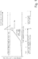
- Figure 1 provides a generic graphic presentation of the heat conditions encountered by munitions when functioning in their intended states and modes of use.
- a munition has a long dwell time in the chamber of a weapon, such as a gun or cannon, heat can be transferred from the barrel of the weapon to the projectile body.
- the projectile In longer dwell-time weapons, the projectile must remain intact to allow for proper ammunition function and heat flow must be attenuated to preclude inadvertent activation of the device.
- Shoulder launched munitions like the lightweight anti-armor weapon (“LAW”) are housed in an expendable housing that eliminates the need for states and modes A-C as the munition is housed in a tube.
- LAW lightweight anti-armor weapon
- munition such as an ammunition cartridge, shell or shoulder launched weapon are stored and when the munition is exposed to heat beyond identified storage conditions (normally in the range of 170° C) the munitions are subject to premature detonation.
- identified storage conditions normally in the range of 170° C
- the munitions are subject to premature detonation.
- the heat generated by a fire increases over time and is generally over a much longer duration (compared to the heat transferred into a cartridge when it is chambered and dwelling in a cannon barrel).
- the 1st energetic event is deflagration of the powder.
- fast heating primers generally initiate ignition.
- US 5035181 discloses a thermosensitive pop-out device. It refers to projectiles like artillery, mortars and air dropped bombs which are assembled in the field by screwing fuzes into fuze wells. In hot conditions the sleeved casing releases a fuze that is screwed into a projectile in a One-Step method. When the solder reaches its fusing temperature the spring pushes the internal sleeve holding the fuze which is pushed out of the projectile. The outer sleeve remains in the warhead's casing.
- this device is not suitable for cartridge-type ammunition which has been preassembled at a factory because cartridges do not have openings to which fuzes are loaded just prior to use.
- the present invention provides a mechanism for preventing an unwanted and dangerous detonation of a cartridge-type munition warhead during one of the NATO operational conditions.
- the invention harnesses the increasing heat to initiate a dual or triple action vent that physically separates components improving the venting of energetic materials in a manner that precludes a warhead detonation.
- a device according to the invention is incorporated into cartridge munitions and/or into the ammunition's packaging or storage container, a container that may include "dunnage" (dunnage being the internal packaging material in a munitions' container).
- a device according to the invention is configured at the physical boundary or interface in a munition where (a) one sub-component includes a warhead containing an explosive and (b) a second sub-component houses the IIDS device that may include a fuse. The invention initiates a two or three step process uncoupling and separating these components at a critical time.
- the present invention provides:
- the fuze-munition interface device may comprise a shape memory material that changes shape at the first elevated temperature, thus releasing the fuze when it changes shape.
- the compressed spring may be retained in a compressed state by a shape memory material that changes its shape at an elevated temperature thereby releasing the spring from compression.
- the multi-step separator device further comprises a retaining wire configured to allow rotation of the fuze, when and if the fuze is released.
- the separator device may also include a housing for the detonator and a second solid, fusible material arranged to release the detonator from the housing when it melts.
- This second fusible material preferably has a melting temperature that is above the melting temperature of the first fusible material.
- the separator device further comprises an insulating material configured to guide the heat away from the first fusible material.
- the munition When the fuze is mated to an explosive device at a production facility, the munition is preferably packaged in a box that includes a void in the dunnage, allowing for the physical separation of the fuze from the explosive device. If desired the dunnage can be configured to retain an ammunition belt.
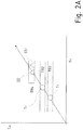
- the two-step or three-step function of the invention allows for the eventual "low-order" deflagration of the explosive load and detonation of IIDS devices in conditions where the energetic events EE1 and EE2 ( Fig. 2A , 2B ) which might occur in a Temperature Range TR4 of about 180°C to 220°C are not contained and where the IIDS device is separated from the warhead before the temperature of the ammunition cartridge reaches TR4.
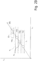
- Figure 2A depicts the nominal activation temperature ranges for a two-step device and Figure 2B depicts the nominal activation ranges for a three-step device.
- Figures 2A and 2B each show the function of the device in a time chart, representing the relevant ammunition state wherein t HE on the x-axis is the time of heat exposure to slow or fast cook off test and T AC on the y-axis is the temperature of the ammunition cartridge.
- the device in the 1st and 2nd phase, the device operates as described with view to Fig. 2A (above) and, when reaching a 3rd temperature T3 threshold in a Temperature Range TR3 of about 160°C to 170°C, the IIDS device is released from the fuze.
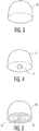
- FIG 3 shows the ogive portion 10 of a projectile having a warhead.
- the ogive 10 includes a fuze with an IIDS device 12 ( Figure 4 ) which is an energetic booster or spitback device housed in a fuze mounted within a spring-ejection device with a ring 16 ( Figure 5 ) as described below.
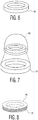
- Figure 6 shows the ring 16 made of a fusible metal alloy or plastic material designed to melt at an elevated temperature above the temperature at which the munition is designed to detonate, at least at about 160°C for example.
- This ring surrounds the IIDS device which is mounted in the ogive fuze assembly 10, as illustrated in Figure 7 .
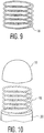
- a compressed spring 18 Embedded in the fusible ring 16 is a compressed spring 18 which is shown in a phantom view of the compressed spring 18 encased in fusible material in Figure 8 and in Figure 9 in uncompressed form. The spring 18 is released when the fusible material melts thereby separating the ogive 10 housing fuze 12 from the warhead 20 ( Figure 10 ).
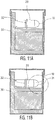
- a void 31 in the packing container 30 allows the ammunition component housing the IIDS 12 to separate, physically segregate and vent a deflagrating explosion, thereby preventing a detonation event (see Figure 11B ).
- the void 31 must provide for an unobstructed volume in all approved UN stacking configurations.
- the packaging 30 is configured to retain (linked or unlinked) ammunition in position, while providing adequate unobstructed volume allowing for ammunition sub-components to separate (see Figure 11C ). Where spit-back charges are utilized, the void 31 provides for separation and rotation of the IIDS device 12.
- the package 30, dunnage and retention configuration 32 work in multiple orientations (see Figures 11D and 11E ).
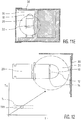
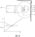
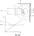
- FIGS. 12 to 15D each show a cut-away view of ammunition in a UN munition container together with a time chart showing the relevant ammunition state wherein t HE on the x-axis is the time of heat exposure to slow or fast cook off test and T AC on the y-axis is the temperature of the ammunition cartridge.
- a phase change of a material or an activation of a memory metal occurs at a first temperature threshold T 1 so that the sub-components 10, 20 are released from each other.
- TR1 Temporal Range 1
- T 1 first temperature threshold
- a gap 14 occurs between the warhead 20 and the ogive fuze housing 10 (see Figure 12 ).
- the IIDS 12 includes a spit-back device, it is also necessary to make sure that a spit-back jet does not initiate the warhead. Accordingly:
- a housing fabricated from a memory metal or fusible material frees the IIDS device 12 from the ogive 10 at temperatures above Temperature Range TR3 so that a focused spit-back jet does not hit the warhead 20 (see Figures 15A and 15B ).
- the device either rotates the sub-component 20 within a packaged container 30 because the center of gravity 14 of the ogive 10 is facing down (see Figure 14 ) or the IIDS device 12 is released from a housing comprised of a fusible material or memory metal (see Figure 15A , 15B ).
- the device must function in a normal environment that does include exposure to heat in chambering, and from air friction in ballistic flight. Therefore, the inactivated memory metal or solid fusible material must be encased and fitted within the munition so that heat is attenuated in normal function conditions that may include chambering into a weapon's barrel or in a normal ballistic flight. However, in conditions outside of the barrel where the fuze 10 is attached to the warhead, the device shall activate sequentially releasing the fuze 10 and IIDS 12 from the warhead 20.
Landscapes
- Engineering & Computer Science (AREA)
- General Engineering & Computer Science (AREA)
- Chemical & Material Sciences (AREA)
- Aviation & Aerospace Engineering (AREA)
- Combustion & Propulsion (AREA)
- Manufacture And Refinement Of Metals (AREA)
Claims (9)
- Mehrstufen-Separator (16, 18) für einen Zünder, der zur Anordnung in einem Ogive eines Geschosses in einer Kartuschen-Militärmunition konfiguriert ist,
wobei der Zünder einen Detonator (12) mit einem Booster oder einem Spit-Back-Element zum Auslösen einer energetischen Sequenz enthält, die zu einer Detonation höherer Ordnung beim Sprengkörper (20) führt, 1 wobei der Mehrstufen-Separator eine Zünder-Munitions-Schnittstellenvorrichtung zum Sichern des Zünders in einer eingrenzten, nahen Verbindung mit dem Sprengkörper (20) und zum Freigeben des Zünders umfasst, falls und wenn dieser einer äußeren Einwirkung ausgesetzt ist, die eine vorzeitige Detonation auslösen kann,
wobei die äußere Einwirkung eine erste erhöhte Temperatur ist, die oberhalb des Bereich von Betriebstemperaturen liegt, für den die Munition ausgelegt ist;
und wobei die Schnittstellenvorrichtung eine Trennvorrichtung (18) einschließlich eines schmelzbaren Rings (16) umfasst, der zwischen dem Zünder und der Sprengkörper (20) angeordnet ist, um den Zünder von dem Sprengkörper (20) zu trennen und physisch davon zu distanzieren, falls und wenn der Zünder bei der erhöhten Temperatur gelöst wird;
wobei der schmelzbare Ring (16) eine komprimierte Schraubenfeder umfasst, die in ein erstes festes, schmelzbares Material eingebettet ist, das bei einer zweiten erhöhten Temperatur schmilzt, die höher als die erste erhöhte Temperatur ist, und das beim Schmelzen die Feder freigibt. - Mehrstufen-Separator für einen Zünder nach Anspruch 1, gekennzeichnet durch ein Gehäuse für den Detonator umfasst, wobei die Zünder-Munitions-Schnittstellenvorrichtung weiterhin ein zweites festes, schmelzbares Material umfasst, das bei einer dritten erhöhten Temperatur schmilzt, die höher ist als die zweite erhöhte Temperatur, wobei das zweite schmelzbare Material beim Schmelzen den Zünder aus dem Gehäuse freigibt.
- Mehrstufen-Separator für einen Zünder nach Anspruch 1, gekennzeichnet durch ein Gehäuse für den Detonator, wobei die Zünder-Munitions-Schnittstellenvorrichtung aus einem Formgedächtnis-Material besteht, das bei einer dritten erhöhten Temperatur, die höher als die zweite erhöhte Temperatur ist, seine Form verändert, wobei das Formgedächtnis-Material den Detonator aus dem Gehäuse freigibt, wenn das Material seine Form verändert.
- Mehrstufen-Separator für einen Zünder nach Anspruch 1, gekennzeichnet durch einen Haltedraht, der so konfiguriert ist, dass er eine Drehung des Zünders ermöglicht, wenn und falls der Zünder gelöst wird.
- Mehrstufen-Separator für einen Zünder nach Anspruch 1, dadurch gekennzeichnet, dass sie ein Gehäuse für den Detonator umfasst, wobei der Detonator ein Booster-Element oder ein Spit-Back-Element zum Einleiten der energetischen Sequenz beinhaltet und dass die Zünder-Munitions-Schnittstellenvorrichtung ferner ein zweites festes, schmelzbares Material umfasst, das so angeordnet ist, dass es den Booster oder das Spit-Back-Element beim Schmelzen aus dem Gehäuse freisetzt, wobei das zweite schmelzbare Material eine Schmelztemperatur aufweist, die höher ist als die Schmelztemperatur des ersten schmelzbaren Materials.
- Mehrstufen-Separator für einen Zünder nach Anspruch 1, dadurch gekennzeichnet, dass er ein Isoliermaterial enthält, das zur Ableitung der Wärme vom ersten schmelzbaren Material ausgelegt ist.
- Mehrstufen-Separator für einen Zünder nach Anspruch 1, dadurch gekennzeichnet, dass er ein Isoliermaterial enthält, das zur Ableitung der Wärme vom zweiten schmelzbaren Material ausgelegt ist.
- Mehrstufen-Separator für einen Zünder nach wenigstens einem der vorhergehenden Ansprüchen, wobei der Zünder in einer Produktionsanlage mit dem Sprengkörper (20) verbunden ist, und wobei die Munition in einer Kiste (30) verpackt ist, die einen Hohlraum (31) im Staumaterial enthält, der die physische Trennung des Zünders von dem Sprengkörper (20) ermöglicht.
- Mehrstufen-Separator für einen Zünder nach Anspruch 5, dadurch gekennzeichnet, dass das Staumaterial so konfiguriert ist, dass es einen Munitionsgurt hält.
Applications Claiming Priority (2)
| Application Number | Priority Date | Filing Date | Title |
|---|---|---|---|
| US201461981298P | 2014-04-18 | 2014-04-18 | |
| US14/683,319 US9410782B2 (en) | 2014-04-18 | 2015-04-10 | Multi-action fuze and warhead separator fitted to a munition |
Publications (3)
| Publication Number | Publication Date |
|---|---|
| EP2933598A2 EP2933598A2 (de) | 2015-10-21 |
| EP2933598A3 EP2933598A3 (de) | 2016-03-02 |
| EP2933598B1 true EP2933598B1 (de) | 2018-06-06 |
Family
ID=52946445
Family Applications (1)
| Application Number | Title | Priority Date | Filing Date |
|---|---|---|---|
| EP15164129.7A Not-in-force EP2933598B1 (de) | 2014-04-18 | 2015-04-17 | In einer munition angebrachter separator mit mehreren aktionen zum trennen des zünders vom gefechtskopf |
Country Status (2)
| Country | Link |
|---|---|
| US (1) | US9410782B2 (de) |
| EP (1) | EP2933598B1 (de) |
Families Citing this family (5)
| Publication number | Priority date | Publication date | Assignee | Title |
|---|---|---|---|---|
| US9897407B2 (en) | 2014-06-18 | 2018-02-20 | Centinel Shield, Llc | Firearm-mounted camera device with networked control and administration system and method |
| US20180135953A1 (en) | 2016-11-15 | 2018-05-17 | Nostromo Holdings, Llc | Ammunition cartridge with a base plug vent |
| US10378870B1 (en) * | 2018-05-30 | 2019-08-13 | The United States Of America As Represented By The Secretary Of The Army | Energy absorbing flange for meltable fuze plug |
| FR3090086B1 (fr) * | 2018-12-13 | 2020-12-11 | Thales Sa | Dispositif de deconfinement d’un chargement explosif et munition equipee d’un tel dispositif |
| CN114440724A (zh) * | 2022-01-12 | 2022-05-06 | 南京理工大学 | 一种有助于引信瞎火后爆炸物安全处理的弹引接螺结构 |
Family Cites Families (12)
| Publication number | Priority date | Publication date | Assignee | Title |
|---|---|---|---|---|
| US2035497A (en) * | 1934-06-12 | 1936-03-31 | Lynn H Morse | Valve |
| US3665857A (en) * | 1970-11-23 | 1972-05-30 | Us Army | Base ejecting ordnance projectile |
| US5035181A (en) * | 1985-01-22 | 1991-07-30 | The United States Of America As Represented By The Secretary Of The Navy | Thermosensitive pop-out device |
| DE3812552C1 (de) * | 1988-04-15 | 1989-11-09 | Hydac Technology Gmbh, 6603 Sulzbach, De | |
| FR2661725B1 (fr) | 1990-05-03 | 1992-09-25 | Saint Louis Inst | Dispositif pour separer deux espaces en cas d'elevation de temperature, procede pour realiser ce dispositif et munition comportant un tel dispositif. |
| US5311820A (en) * | 1991-01-17 | 1994-05-17 | Thiokol Corporation | Method and apparatus for providing an insensitive munition |
| US7331292B1 (en) | 2004-03-23 | 2008-02-19 | The United States Of America As Represented By The Secretary Of The Navy | Venting system for explosive warheads |
| FR2906606B1 (fr) * | 2006-09-29 | 2010-12-31 | Giat Ind Sa | Dispositif de deconfinement d'une enveloppe d'une munition. |
| US8387536B2 (en) * | 2008-12-04 | 2013-03-05 | Raytheon Company | Interceptor vehicle with extendible arms |
| US8925463B1 (en) | 2009-09-03 | 2015-01-06 | Kms Consulting, Llc | Pressure relief system for gun fired cannon cartridges |
| US9683897B2 (en) * | 2010-03-12 | 2017-06-20 | Bruce W. Nichols | Temperature indicator for electrical equipment |
| US8505458B1 (en) * | 2012-01-27 | 2013-08-13 | The United States Of America As Represented By The Secretary Of The Navy | Venting cap system |
-
2015
- 2015-04-10 US US14/683,319 patent/US9410782B2/en active Active
- 2015-04-17 EP EP15164129.7A patent/EP2933598B1/de not_active Not-in-force
Non-Patent Citations (1)
| Title |
|---|
| None * |
Also Published As
| Publication number | Publication date |
|---|---|
| US9410782B2 (en) | 2016-08-09 |
| EP2933598A3 (de) | 2016-03-02 |
| US20160131466A1 (en) | 2016-05-12 |
| EP2933598A2 (de) | 2015-10-21 |
Similar Documents
| Publication | Publication Date | Title |
|---|---|---|
| CA2768076C (en) | Pressure-relief system for gun fired cannon cartridges | |
| JP5328779B2 (ja) | カートリッジ弾薬、特に訓練用弾薬 | |
| US7107909B2 (en) | Cartridge munition, particularly one of medium caliber | |
| US6308607B1 (en) | Neutralizing munition | |
| US9410782B2 (en) | Multi-action fuze and warhead separator fitted to a munition | |
| JPS6347755Y2 (de) | ||
| US20120240806A1 (en) | Energetics Train Reaction And Method Of Making An Intensive Munitions Detonator | |
| US9562755B2 (en) | Safe and arm mechanisms and methods for explosive devices | |
| US20180135953A1 (en) | Ammunition cartridge with a base plug vent | |
| KR20100095314A (ko) | 유탄의 자폭장치 | |
| US8550004B1 (en) | Riveted cartridge venting | |
| CN114279279B (zh) | 一种弹道安全性好的中大口径线膛火炮榴弹触发引信系统 | |
| US11614313B2 (en) | Pyrotechnic delay element device | |
| FI86108C (fi) | Patron foer hagelgevaer med explosiv projektil. | |
| US9995563B2 (en) | Cartridge with safety fuse in the drive system, and method for producing it | |
| EP3690322B1 (de) | Elektromechanischer kontaktzünder für mehrzweckflugzeugmunition | |
| JP7344771B2 (ja) | 炸薬を放出するデバイス、及びこのようなデバイスが搭載されている軍需品 | |
| US7913608B1 (en) | Weapon with IM-characteristics | |
| CN115325890A (zh) | 一种隔爆型的高安全性点火引信 | |
| CA2563392C (en) | Cartridge munition, particularly one of medium calibre | |
| WO2018122846A1 (en) | Unified booster for artillery munition fuses enabling detonating of both explosion and ejection type shells | |
| KR101243770B1 (ko) | 기폭압의 누출 방지구조가 구비된 신관 | |
| WIŚNIEWSKI | Different Types of Ventilation Systems of Munitions | |
| CA3180516A1 (en) | Launching device and method for assembling projectiles in a launching device | |
| PL207165B1 (pl) | Zapalnik uderzeniowy z automatyczną regulacją zwłoki |
Legal Events
| Date | Code | Title | Description |
|---|---|---|---|
| PUAI | Public reference made under article 153(3) epc to a published international application that has entered the european phase |
Free format text: ORIGINAL CODE: 0009012 |
|
| AK | Designated contracting states |
Kind code of ref document: A2 Designated state(s): AL AT BE BG CH CY CZ DE DK EE ES FI FR GB GR HR HU IE IS IT LI LT LU LV MC MK MT NL NO PL PT RO RS SE SI SK SM TR |
|
| AX | Request for extension of the european patent |
Extension state: BA ME |
|
| PUAL | Search report despatched |
Free format text: ORIGINAL CODE: 0009013 |
|
| AK | Designated contracting states |
Kind code of ref document: A3 Designated state(s): AL AT BE BG CH CY CZ DE DK EE ES FI FR GB GR HR HU IE IS IT LI LT LU LV MC MK MT NL NO PL PT RO RS SE SI SK SM TR |
|
| AX | Request for extension of the european patent |
Extension state: BA ME |
|
| RIC1 | Information provided on ipc code assigned before grant |
Ipc: F42B 39/14 20060101ALI20160128BHEP Ipc: F42C 15/44 20060101ALI20160128BHEP Ipc: F42B 15/36 20060101AFI20160128BHEP Ipc: F42B 39/20 20060101ALI20160128BHEP |
|
| RIN1 | Information on inventor provided before grant (corrected) |
Inventor name: BRUNO, NICOLAS HORATIO Inventor name: SULLIVAN, KEVIN MICHAEL |
|
| 17P | Request for examination filed |
Effective date: 20160902 |
|
| RBV | Designated contracting states (corrected) |
Designated state(s): AL AT BE BG CH CY CZ DE DK EE ES FI FR GB GR HR HU IE IS IT LI LT LU LV MC MK MT NL NO PL PT RO RS SE SI SK SM TR |
|
| R17P | Request for examination filed (corrected) |
Effective date: 20160902 |
|
| RAP1 | Party data changed (applicant data changed or rights of an application transferred) |
Owner name: NOSTROMO HOLDINGS, LLC |
|
| STAA | Information on the status of an ep patent application or granted ep patent |
Free format text: STATUS: EXAMINATION IS IN PROGRESS |
|
| 17Q | First examination report despatched |
Effective date: 20170404 |
|
| GRAP | Despatch of communication of intention to grant a patent |
Free format text: ORIGINAL CODE: EPIDOSNIGR1 |
|
| STAA | Information on the status of an ep patent application or granted ep patent |
Free format text: STATUS: GRANT OF PATENT IS INTENDED |
|
| INTG | Intention to grant announced |
Effective date: 20171206 |
|
| GRAS | Grant fee paid |
Free format text: ORIGINAL CODE: EPIDOSNIGR3 |
|
| GRAA | (expected) grant |
Free format text: ORIGINAL CODE: 0009210 |
|
| STAA | Information on the status of an ep patent application or granted ep patent |
Free format text: STATUS: THE PATENT HAS BEEN GRANTED |
|
| AK | Designated contracting states |
Kind code of ref document: B1 Designated state(s): AL AT BE BG CH CY CZ DE DK EE ES FI FR GB GR HR HU IE IS IT LI LT LU LV MC MK MT NL NO PL PT RO RS SE SI SK SM TR |
|
| REG | Reference to a national code |
Ref country code: GB Ref legal event code: FG4D |
|
| REG | Reference to a national code |
Ref country code: CH Ref legal event code: EP Ref country code: AT Ref legal event code: REF Ref document number: 1006587 Country of ref document: AT Kind code of ref document: T Effective date: 20180615 |
|
| REG | Reference to a national code |
Ref country code: IE Ref legal event code: FG4D |
|
| REG | Reference to a national code |
Ref country code: DE Ref legal event code: R096 Ref document number: 602015011603 Country of ref document: DE |
|
| REG | Reference to a national code |
Ref country code: CH Ref legal event code: NV Representative=s name: RIEDERER HASLER AND PARTNER PATENTANWAELTE AG, CH |
|
| REG | Reference to a national code |
Ref country code: NL Ref legal event code: MP Effective date: 20180606 |
|
| REG | Reference to a national code |
Ref country code: LT Ref legal event code: MG4D |
|
| PG25 | Lapsed in a contracting state [announced via postgrant information from national office to epo] |
Ref country code: CY Free format text: LAPSE BECAUSE OF FAILURE TO SUBMIT A TRANSLATION OF THE DESCRIPTION OR TO PAY THE FEE WITHIN THE PRESCRIBED TIME-LIMIT Effective date: 20180606 Ref country code: LT Free format text: LAPSE BECAUSE OF FAILURE TO SUBMIT A TRANSLATION OF THE DESCRIPTION OR TO PAY THE FEE WITHIN THE PRESCRIBED TIME-LIMIT Effective date: 20180606 Ref country code: SE Free format text: LAPSE BECAUSE OF FAILURE TO SUBMIT A TRANSLATION OF THE DESCRIPTION OR TO PAY THE FEE WITHIN THE PRESCRIBED TIME-LIMIT Effective date: 20180606 Ref country code: BG Free format text: LAPSE BECAUSE OF FAILURE TO SUBMIT A TRANSLATION OF THE DESCRIPTION OR TO PAY THE FEE WITHIN THE PRESCRIBED TIME-LIMIT Effective date: 20180906 Ref country code: FI Free format text: LAPSE BECAUSE OF FAILURE TO SUBMIT A TRANSLATION OF THE DESCRIPTION OR TO PAY THE FEE WITHIN THE PRESCRIBED TIME-LIMIT Effective date: 20180606 Ref country code: ES Free format text: LAPSE BECAUSE OF FAILURE TO SUBMIT A TRANSLATION OF THE DESCRIPTION OR TO PAY THE FEE WITHIN THE PRESCRIBED TIME-LIMIT Effective date: 20180606 Ref country code: NO Free format text: LAPSE BECAUSE OF FAILURE TO SUBMIT A TRANSLATION OF THE DESCRIPTION OR TO PAY THE FEE WITHIN THE PRESCRIBED TIME-LIMIT Effective date: 20180906 |
|
| PG25 | Lapsed in a contracting state [announced via postgrant information from national office to epo] |
Ref country code: LV Free format text: LAPSE BECAUSE OF FAILURE TO SUBMIT A TRANSLATION OF THE DESCRIPTION OR TO PAY THE FEE WITHIN THE PRESCRIBED TIME-LIMIT Effective date: 20180606 Ref country code: GR Free format text: LAPSE BECAUSE OF FAILURE TO SUBMIT A TRANSLATION OF THE DESCRIPTION OR TO PAY THE FEE WITHIN THE PRESCRIBED TIME-LIMIT Effective date: 20180907 Ref country code: HR Free format text: LAPSE BECAUSE OF FAILURE TO SUBMIT A TRANSLATION OF THE DESCRIPTION OR TO PAY THE FEE WITHIN THE PRESCRIBED TIME-LIMIT Effective date: 20180606 Ref country code: RS Free format text: LAPSE BECAUSE OF FAILURE TO SUBMIT A TRANSLATION OF THE DESCRIPTION OR TO PAY THE FEE WITHIN THE PRESCRIBED TIME-LIMIT Effective date: 20180606 |
|
| REG | Reference to a national code |
Ref country code: AT Ref legal event code: MK05 Ref document number: 1006587 Country of ref document: AT Kind code of ref document: T Effective date: 20180606 |
|
| PG25 | Lapsed in a contracting state [announced via postgrant information from national office to epo] |
Ref country code: NL Free format text: LAPSE BECAUSE OF FAILURE TO SUBMIT A TRANSLATION OF THE DESCRIPTION OR TO PAY THE FEE WITHIN THE PRESCRIBED TIME-LIMIT Effective date: 20180606 |
|
| PG25 | Lapsed in a contracting state [announced via postgrant information from national office to epo] |
Ref country code: AT Free format text: LAPSE BECAUSE OF FAILURE TO SUBMIT A TRANSLATION OF THE DESCRIPTION OR TO PAY THE FEE WITHIN THE PRESCRIBED TIME-LIMIT Effective date: 20180606 Ref country code: PL Free format text: LAPSE BECAUSE OF FAILURE TO SUBMIT A TRANSLATION OF THE DESCRIPTION OR TO PAY THE FEE WITHIN THE PRESCRIBED TIME-LIMIT Effective date: 20180606 Ref country code: CZ Free format text: LAPSE BECAUSE OF FAILURE TO SUBMIT A TRANSLATION OF THE DESCRIPTION OR TO PAY THE FEE WITHIN THE PRESCRIBED TIME-LIMIT Effective date: 20180606 Ref country code: SK Free format text: LAPSE BECAUSE OF FAILURE TO SUBMIT A TRANSLATION OF THE DESCRIPTION OR TO PAY THE FEE WITHIN THE PRESCRIBED TIME-LIMIT Effective date: 20180606 Ref country code: RO Free format text: LAPSE BECAUSE OF FAILURE TO SUBMIT A TRANSLATION OF THE DESCRIPTION OR TO PAY THE FEE WITHIN THE PRESCRIBED TIME-LIMIT Effective date: 20180606 Ref country code: EE Free format text: LAPSE BECAUSE OF FAILURE TO SUBMIT A TRANSLATION OF THE DESCRIPTION OR TO PAY THE FEE WITHIN THE PRESCRIBED TIME-LIMIT Effective date: 20180606 Ref country code: IS Free format text: LAPSE BECAUSE OF FAILURE TO SUBMIT A TRANSLATION OF THE DESCRIPTION OR TO PAY THE FEE WITHIN THE PRESCRIBED TIME-LIMIT Effective date: 20181006 |
|
| PG25 | Lapsed in a contracting state [announced via postgrant information from national office to epo] |
Ref country code: SM Free format text: LAPSE BECAUSE OF FAILURE TO SUBMIT A TRANSLATION OF THE DESCRIPTION OR TO PAY THE FEE WITHIN THE PRESCRIBED TIME-LIMIT Effective date: 20180606 Ref country code: IT Free format text: LAPSE BECAUSE OF FAILURE TO SUBMIT A TRANSLATION OF THE DESCRIPTION OR TO PAY THE FEE WITHIN THE PRESCRIBED TIME-LIMIT Effective date: 20180606 |
|
| REG | Reference to a national code |
Ref country code: DE Ref legal event code: R097 Ref document number: 602015011603 Country of ref document: DE |
|
| PLBE | No opposition filed within time limit |
Free format text: ORIGINAL CODE: 0009261 |
|
| STAA | Information on the status of an ep patent application or granted ep patent |
Free format text: STATUS: NO OPPOSITION FILED WITHIN TIME LIMIT |
|
| 26N | No opposition filed |
Effective date: 20190307 |
|
| PG25 | Lapsed in a contracting state [announced via postgrant information from national office to epo] |
Ref country code: SI Free format text: LAPSE BECAUSE OF FAILURE TO SUBMIT A TRANSLATION OF THE DESCRIPTION OR TO PAY THE FEE WITHIN THE PRESCRIBED TIME-LIMIT Effective date: 20180606 Ref country code: DK Free format text: LAPSE BECAUSE OF FAILURE TO SUBMIT A TRANSLATION OF THE DESCRIPTION OR TO PAY THE FEE WITHIN THE PRESCRIBED TIME-LIMIT Effective date: 20180606 |
|
| PG25 | Lapsed in a contracting state [announced via postgrant information from national office to epo] |
Ref country code: AL Free format text: LAPSE BECAUSE OF FAILURE TO SUBMIT A TRANSLATION OF THE DESCRIPTION OR TO PAY THE FEE WITHIN THE PRESCRIBED TIME-LIMIT Effective date: 20180606 |
|
| REG | Reference to a national code |
Ref country code: BE Ref legal event code: MM Effective date: 20190430 |
|
| PG25 | Lapsed in a contracting state [announced via postgrant information from national office to epo] |
Ref country code: MC Free format text: LAPSE BECAUSE OF FAILURE TO SUBMIT A TRANSLATION OF THE DESCRIPTION OR TO PAY THE FEE WITHIN THE PRESCRIBED TIME-LIMIT Effective date: 20180606 Ref country code: LU Free format text: LAPSE BECAUSE OF NON-PAYMENT OF DUE FEES Effective date: 20190417 |
|
| PG25 | Lapsed in a contracting state [announced via postgrant information from national office to epo] |
Ref country code: BE Free format text: LAPSE BECAUSE OF NON-PAYMENT OF DUE FEES Effective date: 20190430 |
|
| PG25 | Lapsed in a contracting state [announced via postgrant information from national office to epo] |
Ref country code: TR Free format text: LAPSE BECAUSE OF FAILURE TO SUBMIT A TRANSLATION OF THE DESCRIPTION OR TO PAY THE FEE WITHIN THE PRESCRIBED TIME-LIMIT Effective date: 20180606 |
|
| PG25 | Lapsed in a contracting state [announced via postgrant information from national office to epo] |
Ref country code: IE Free format text: LAPSE BECAUSE OF NON-PAYMENT OF DUE FEES Effective date: 20190417 |
|
| PG25 | Lapsed in a contracting state [announced via postgrant information from national office to epo] |
Ref country code: PT Free format text: LAPSE BECAUSE OF FAILURE TO SUBMIT A TRANSLATION OF THE DESCRIPTION OR TO PAY THE FEE WITHIN THE PRESCRIBED TIME-LIMIT Effective date: 20181008 |
|
| PG25 | Lapsed in a contracting state [announced via postgrant information from national office to epo] |
Ref country code: MT Free format text: LAPSE BECAUSE OF FAILURE TO SUBMIT A TRANSLATION OF THE DESCRIPTION OR TO PAY THE FEE WITHIN THE PRESCRIBED TIME-LIMIT Effective date: 20180606 Ref country code: HU Free format text: LAPSE BECAUSE OF FAILURE TO SUBMIT A TRANSLATION OF THE DESCRIPTION OR TO PAY THE FEE WITHIN THE PRESCRIBED TIME-LIMIT; INVALID AB INITIO Effective date: 20150417 |
|
| PGFP | Annual fee paid to national office [announced via postgrant information from national office to epo] |
Ref country code: FR Payment date: 20210422 Year of fee payment: 7 Ref country code: DE Payment date: 20210429 Year of fee payment: 7 |
|
| PGFP | Annual fee paid to national office [announced via postgrant information from national office to epo] |
Ref country code: GB Payment date: 20210429 Year of fee payment: 7 Ref country code: CH Payment date: 20210525 Year of fee payment: 7 |
|
| PG25 | Lapsed in a contracting state [announced via postgrant information from national office to epo] |
Ref country code: MK Free format text: LAPSE BECAUSE OF FAILURE TO SUBMIT A TRANSLATION OF THE DESCRIPTION OR TO PAY THE FEE WITHIN THE PRESCRIBED TIME-LIMIT Effective date: 20180606 |
|
| REG | Reference to a national code |
Ref country code: DE Ref legal event code: R119 Ref document number: 602015011603 Country of ref document: DE |
|
| REG | Reference to a national code |
Ref country code: CH Ref legal event code: PL |
|
| GBPC | Gb: european patent ceased through non-payment of renewal fee |
Effective date: 20220417 |
|
| PG25 | Lapsed in a contracting state [announced via postgrant information from national office to epo] |
Ref country code: LI Free format text: LAPSE BECAUSE OF NON-PAYMENT OF DUE FEES Effective date: 20220430 Ref country code: GB Free format text: LAPSE BECAUSE OF NON-PAYMENT OF DUE FEES Effective date: 20220417 Ref country code: FR Free format text: LAPSE BECAUSE OF NON-PAYMENT OF DUE FEES Effective date: 20220430 Ref country code: DE Free format text: LAPSE BECAUSE OF NON-PAYMENT OF DUE FEES Effective date: 20221103 Ref country code: CH Free format text: LAPSE BECAUSE OF NON-PAYMENT OF DUE FEES Effective date: 20220430 |