EP2933620A2 - Système et procédé pour estimer la température de rotor d'un moteur - Google Patents
Système et procédé pour estimer la température de rotor d'un moteur Download PDFInfo
- Publication number
- EP2933620A2 EP2933620A2 EP14188955.0A EP14188955A EP2933620A2 EP 2933620 A2 EP2933620 A2 EP 2933620A2 EP 14188955 A EP14188955 A EP 14188955A EP 2933620 A2 EP2933620 A2 EP 2933620A2
- Authority
- EP
- European Patent Office
- Prior art keywords
- motor
- rotor
- temperature
- energy loss
- model
- Prior art date
- Legal status (The legal status is an assumption and is not a legal conclusion. Google has not performed a legal analysis and makes no representation as to the accuracy of the status listed.)
- Granted
Links
Images


Classifications
-
- H—ELECTRICITY
- H02—GENERATION; CONVERSION OR DISTRIBUTION OF ELECTRIC POWER
- H02P—CONTROL OR REGULATION OF ELECTRIC MOTORS, ELECTRIC GENERATORS OR DYNAMO-ELECTRIC CONVERTERS; CONTROLLING TRANSFORMERS, REACTORS OR CHOKE COILS
- H02P23/00—Arrangements or methods for the control of AC motors characterised by a control method other than vector control
- H02P23/14—Estimation or adaptation of motor parameters, e.g. rotor time constant, flux, speed, current or voltage
-
- G—PHYSICS
- G01—MEASURING; TESTING
- G01K—MEASURING TEMPERATURE; MEASURING QUANTITY OF HEAT; THERMALLY-SENSITIVE ELEMENTS NOT OTHERWISE PROVIDED FOR
- G01K13/00—Thermometers specially adapted for specific purposes
- G01K13/04—Thermometers specially adapted for specific purposes for measuring temperature of moving solid bodies
- G01K13/08—Thermometers specially adapted for specific purposes for measuring temperature of moving solid bodies in rotary movement
-
- H—ELECTRICITY
- H02—GENERATION; CONVERSION OR DISTRIBUTION OF ELECTRIC POWER
- H02P—CONTROL OR REGULATION OF ELECTRIC MOTORS, ELECTRIC GENERATORS OR DYNAMO-ELECTRIC CONVERTERS; CONTROLLING TRANSFORMERS, REACTORS OR CHOKE COILS
- H02P23/00—Arrangements or methods for the control of AC motors characterised by a control method other than vector control
- H02P23/0077—Characterised by the use of a particular software algorithm
Definitions
- the present invention relates to a system and method for estimating temperature of a rotor of a motor, and particularly, to a system and method for estimating temperature of a rotor of a motor to calculate temperature variation of the rotor using a measured data-based thermal model (e.g., thermal impedance model) and an energy loss model to then estimate temperature of the rotor with the temperature variation of the calculated temperature variation of the rotor.
- a measured data-based thermal model e.g., thermal impedance model
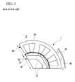
- FIG. 1 is an exemplary drawing illustrating a schematic structure of a driving motor used in an environmentally-friendly vehicle, in which an air gap is formed between the stator 20 and rotor 10, a housing 40 is installed extraneous to the stator 20 to form a cooling channel 42, and oil or coolant flows in the cooling channel 42 to cool a motor 1.
- the rotor 10 includes permanent magnets 12 and an iron core 14, and the stator 20 includes an iron core 22 and a coil 24.
- the motor 1 of the environmentally-friendly vehicle may have different output and control performances as characteristics of the permanent magnets 12 embedded within the rotor 10 are varied.
- magnetic flux of the permanent magnet 12 decreases as temperature increases, thereby resulting in a decreased output.
- compensation control is required as temperature of the rotor varies.
- the permanent magnets 12 are positioned inside of the rotor 10, causing difficult in attaching a temperature sensor configured to detect the permanent magnets 12, and a method for estimating the temperature of the rotor needs to be developed. Meanwhile, a method is known in which a temperature sensor is attached to a stator coil to detect temperature of a stator and the detected temperature of the stator is used to estimate temperature of a motor. However, this known method does not teach estimating temperature of the rotor and thus may not provide appropriate temperature compensation control according to temperature variation of the rotor.
- the present invention provides a method for estimating temperature of a rotor of a motor to improve performance and efficiency of a motor control system according to accurate temperature estimation of the rotor and to provide a motor-related fail-safe capability, by using an actual measured data-based thermal model (e.g., thermal impedance model) and an energy loss model that calculate temperature variation of the rotor and then use the calculated temperature variation of the rotor to estimate temperature of the rotor.
- an actual measured data-based thermal model e.g., thermal impedance model
- an energy loss model that calculate temperature variation of the rotor and then use the calculated temperature variation of the rotor to estimate temperature of the rotor.
- an exemplary embodiment of the present invention provides a method for estimating temperature of a rotor of a motor that may include: calculating energy loss of the motor using driving conditions of the motor; calculating temperature variation of the rotor at a predetermined reference temperature using the calculated energy loss and thermal resistances of the rotor and a stator of the motor; and estimating rotor temperature with the predetermined reference temperature using the temperature variation of the rotor.
- the motor may be an embedded permanent magnet type of synchronous electric motor.
- the driving conditions of the motor may include a torque instruction, a motor speed, a reference voltage, and a switching frequency.
- the predetermined reference temperature may be a cooling temperature of the motor.
- the calculation of the energy loss of the motor may use response surface modeling and an approximate model as an actual measured data-based energy loss model.
- the calculation of the temperature variation of the rotor of the motor may use a thermal impedance model as an actual measured data-based thermal model.
- another exemplary embodiment of the present invention provides a method for estimating temperature of a rotor of a motor that may include: a motor operating as a driving motor of an environmentally-friendly vehicle; and a controller configured to estimate a temperature of a rotor of the motor.
- the controller may be operated by a predetermined program for executing the method for estimating temperature of the rotor of the motor.
- the method for estimating temperature of the rotor of the motor may be provided to improve the performance and efficiency of the motor control system according to more accurate temperature estimation of the rotor in addition to providing the motor-related fail-safe capability, through the actual measured data-based thermal model (e.g., thermal impedance model) and the energy loss model that calculate the temperature variation of the rotor, and then uses the calculated temperature variation of the rotor to estimate the temperature of the rotor.
- thermal model e.g., thermal impedance model
- the energy loss model that calculate the temperature variation of the rotor
- vehicle or “vehicular” or other similar term as used herein is inclusive of motor vehicles in general such as passenger automobiles including sports utility vehicles (SUV), buses, trucks, various commercial vehicles, watercraft including a variety of boats and ships, aircraft, and the like, and includes hybrid vehicles, electric vehicles, plug-in hybrid electric vehicles, hydrogen-powered vehicles and other alternative fuel vehicles (e.g. fuels derived from resources other than petroleum).
- a hybrid vehicle is a vehicle that has two or more sources of power, for example both gasoline-powered and electric-powered vehicles.
- controller/control unit refers to a hardware device that includes a memory and a processor.
- the memory is configured to store the modules and the processor is specifically configured to execute said modules to perform one or more processes which are described further below.
- control logic of the present invention may be embodied as non-transitory computer readable media on a computer readable medium containing executable program instructions executed by a processor, controller/control unit or the like.
- the computer readable mediums include, but are not limited to, ROM, RAM, compact disc (CD)-ROMs, magnetic tapes, floppy disks, flash drives, smart cards and optical data storage devices.
- the computer readable recording medium can also be distributed in network coupled computer systems so that the computer readable media is stored and executed in a distributed fashion, e.g., by a telematics server or a Controller Area Network (CAN).
- a telematics server or a Controller Area Network (CAN).
- CAN Controller Area Network
- FIG. 4 is an exemplary drawing illustrating a controller 100 configured to execute logic of a method for estimating temperature of a rotor of a motor according to an exemplary embodiment of the present invention.
- a controller 100 configured to execute a method for estimating temperature of a rotor of a motor according to an exemplary embodiment of the present invention may include: an energy loss calculation module 110 configured to detect a driving condition of a motor 1 and to calculate energy loss of the motor 1 with the detected driving condition; a rotor temperature variation calculation module 120 configured to use thermal resistances of the rotor 10 and the stator 100 to calculate the temperature variation of the rotor 10 at a predetermined reference temperature using the energy loss calculated by the energy loss calculation module 110; and a rotor temperature estimation module 130 configured to estimate temperature of the rotor 10 in the predetermined reference temperature using the temperature variation of the rotor 10 calculated by the rotor temperature variation calculation module 120.
- the motor 1 may be an embedded permanent magnet type of synchronous electric motor used as a driving motor in the environmentally-friendly vehicle, but it should be understood that the scope of the present invention is not limited thereto. Even if the motor is not the embedded permanent magnet type of synchronous electric motor, the technical spirit of the present invention may be applicable to motors in which the permanent magnets are substantially embedded in the rotor.
- Driving conditions of the motor 1 may include a torque instruction for the motor 1, a motor speed, a reference voltage, and a switching frequency, and a detailed description of the driving conditions will be omitted since they may be determined by a person of ordinary skill in the art using disclosed technologies.
- the predetermined reference temperature may be a temperature of a coolant or oil that flows in the cooling channel 42 of the motor 1, but it should be understood that the scope of the present invention is not limited thereto. If the predetermined reference temperature is not the temperature of the coolant or oil but a substantially configurable temperature as the reference temperature, the technical spirit of the present invention may be applicable thereto.
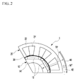
- Energy loss (P loss(Motor) ) of the motor 1 may be, as shown in FIGS. 2 and 3 , a sum of energy lost in a stator core, a stator coil, an air gap, an iron core of the rotor, and the permanent magnets.
- the energy loss may be calculated from a coolant temperature (T coolant ) and a rotor temperature (T rotor ), and the rotor temperature may be estimated using the energy losses and the coolant temperature.
- T coolant coolant temperature
- T rotor rotor temperature
- the rotor temperature may be calculated by the following equation and may be estimated when the energy loss and the coolant temperature are disclosed.
- TP a temperature difference between the coolant temperature (T coolant ) and the rotor temperature (T rotor ), and WT represents the coolant temperature.
- R th _ total T P
- Z th_ total Z th ⁇ 1 + Z th ⁇ 2 + Z th ⁇ 3 + Z th ⁇ 4 + Z th ⁇ 5
- Z th_total represents overall thermal impedance
- R represents thermal resistance
- t represents a measurement time
- the thermal impedance may be determined by a configuration for measuring actual temperature of the rotor of the motor, as shown in FIG. 6 .
- the temperature of the rotor 10 may be continuously measured through the slip ring SH and a signal processor (not shown) in a laboratory.
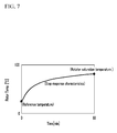
- the temperatures of the rotor 10 measured by the configuration of FIG. 6 may be represented by a graph as shown in FIG. 7 .
- the temperature of the rotor measured in the laboratory may have a step response characteristic, and the temperature of the rotor may be measured multiple times.
- Losses of the motor 1 may generally consist of copper loss, iron loss, wind loss, friction loss, etc., and accurate loss estimation of the iron loss may be difficult since the iron loss may be affected by a driving current and a rotation speed.
- experimental data-based loss modeling is recommended, and accordingly, energy loss calculation in the exemplary embodiment of the present invention may use response surface modeling and/or an approximate model as an actual measured data-based energy loss model.
- the response surface modeling is, as is well-known to a person of ordinary skill in the art, a statistical analysis method for a response surface formed by variation of responses, when multiple descriptive variables (e.g., independent parameters) complicatedly affect some response variables (e.g., dependent parameters).
- functional relations between the independent parameters and the dependent parameters may be assumed from data (e.g., experimental results) to estimate an amount of the response of each dependent parameter according to variations of the independent parameters.
- the independent parameters for the motor energy loss modeling may be the torque instruction (e.g., current), the motor speed, the reference voltage, and the switching frequency, and the dependent parameter may be the energy loss.
- the response surface modeling may be applied to the exemplary embodiment of the present invention because to estimate the temperature using the aforementioned thermal model, loss estimation according to the driving conditions of the motor 1 (e.g., the independent parameters) may be critical and analysis-based loss estimation may be difficult to apply thereto due to various considered factors.
- the response surface modeling based on an experimental plan may be used for the energy loss estimation, and through the response surface modeling, the a more accurate approximate response model may be created by performing a minimum number of experiments, thereby reducing a development period of the motor.
- FIG. 8 illustrates an exemplary process of energy loss-estimating modeling applicable to the exemplary embodiment of the present invention.
- the present invention may be configured to determine the optimal approximate model for the energy loss estimation, through the process shown in FIG. 8 . After determining the optimal approximate model, the actual model may be replaced by the approximate model, and the approximate model may be used to perform an approximate optimization process.
- the approximate optimization process is a method in which a difference between the actual model and the approximate model may be narrowed to converge to optimal design values (model). How to determine the initial approximate model when doing the response surface modeling may determine modeling accuracy (e.g., error level), which is a fact that is well-known to a person of ordinary skill in the art.
- Equations for the approximate model may be a linear approximate model Equation 1 and a [linear + square] approximate model Equation 2 as follows.
- a variance analysis for selecting the optimal model may be applied as a statistical analysis method.
- FIG. 5 is an exemplary flowchart of the method for estimating the temperature of the rotor of the motor according to the exemplary embodiment of the present invention.
- the energy loss calculation module 110 of the controller 100 may use the aforementioned energy loss model to calculate energy loss ( P ⁇ ) of the motor 1 using driving conditions of the motor 1 (e.g., a torque instruction, a motor speed, a reference voltage, a switching frequency, etc.) (S100 and S200).
- the rotor temperature variation calculation module 120 of the controller 100 may then use the calculated energy loss ( P ⁇ ) and the aforementioned thermal resistance ( R th_total ) of the rotor 10 and the stator 20 of the motor 1 to calculate temperature variation ( ⁇ T ) of the rotor 10 at a predetermined reference temperature (e.g., a coolant temperature) according to the following equation (S300).
- ⁇ ⁇ T P ⁇ ⁇ R th _ total
- the rotor temperature estimation module 130 of the controller 100 may be configured to estimate and output the rotor temperature ( T rotor )using the following equation based on the temperature variation of the rotor in the predetermined reference temperature (S400).
- T ⁇ rotor T coolant + ⁇ ⁇ T
- the actual measured data-based thermal model e.g., thermal impedance model
- the energy loss model may be used to calculate the temperature variation of the rotor and then the calculated temperature variation of the rotor may be used to estimate the rotor temperature, thereby providing the motor-related fail-safe capability by information about the estimated rotor temperature as well as improving the performance and efficiency of the motor control system by the more accurately estimated rotor temperature.
Landscapes
- Engineering & Computer Science (AREA)
- Power Engineering (AREA)
- Physics & Mathematics (AREA)
- General Physics & Mathematics (AREA)
- Control Of Ac Motors In General (AREA)
- Control Of Electric Motors In General (AREA)
Applications Claiming Priority (1)
| Application Number | Priority Date | Filing Date | Title |
|---|---|---|---|
| KR1020140044239A KR101542994B1 (ko) | 2014-04-14 | 2014-04-14 | 모터의 회전자 온도 추정 방법 |
Publications (3)
| Publication Number | Publication Date |
|---|---|
| EP2933620A2 true EP2933620A2 (fr) | 2015-10-21 |
| EP2933620A3 EP2933620A3 (fr) | 2015-11-04 |
| EP2933620B1 EP2933620B1 (fr) | 2020-04-29 |
Family
ID=51730385
Family Applications (1)
| Application Number | Title | Priority Date | Filing Date |
|---|---|---|---|
| EP14188955.0A Active EP2933620B1 (fr) | 2014-04-14 | 2014-10-15 | Système et procédé pour estimer la température de rotor d'un moteur |
Country Status (4)
| Country | Link |
|---|---|
| US (1) | US9584058B2 (fr) |
| EP (1) | EP2933620B1 (fr) |
| KR (1) | KR101542994B1 (fr) |
| CN (1) | CN104978477A (fr) |
Families Citing this family (27)
| Publication number | Priority date | Publication date | Assignee | Title |
|---|---|---|---|---|
| US9372235B2 (en) * | 2014-09-30 | 2016-06-21 | Deere & Company | Methods of estimating rotor magnet temperature and systems thereof |
| CN105953944B (zh) * | 2016-04-21 | 2019-06-11 | 同济大学 | 电动机的转子温度的估计方法 |
| US10208649B2 (en) * | 2016-06-24 | 2019-02-19 | Toyota Jidosha Kabushiki Kaisha | Estimator and estimator system |
| EP3462600A1 (fr) * | 2017-09-29 | 2019-04-03 | Siemens Aktiengesellschaft | Machine asynchrone à efficacité énergétique |
| CN109752651B (zh) * | 2017-11-03 | 2021-08-17 | 株洲中车时代电气股份有限公司 | 一种牵引电机超温故障预测的方法及系统 |
| WO2019095009A1 (fr) * | 2017-11-17 | 2019-05-23 | Anca Pty Ltd | Procédé et système de régulation de température constante de broches motorisées |
| CN109808672B (zh) * | 2017-11-22 | 2021-04-16 | 上海汽车集团股份有限公司 | 一种混合动力汽车扭矩控制方法及装置 |
| KR102383437B1 (ko) * | 2017-12-05 | 2022-04-07 | 현대자동차주식회사 | 차량 모터 제어 장치, 그를 포함한 시스템 및 그 방법 |
| CN108390617B (zh) * | 2017-12-11 | 2020-01-03 | 深圳腾势新能源汽车有限公司 | 电机转子温度监测方法、装置、存储介质和计算机设备 |
| US11740607B2 (en) * | 2018-08-30 | 2023-08-29 | Abb Schweiz Ag | Method and system for monitoring condition of electric drives |
| CN111211719B (zh) * | 2018-11-06 | 2021-09-24 | 株洲中车时代电气股份有限公司 | 一种永磁同步电机转子磁钢温度估算方法及系统 |
| GB2579633B (en) * | 2018-12-07 | 2023-02-01 | Zf Automotive Uk Ltd | A method of characterising a permanent magnet synchronous motor |
| CN110333443B (zh) * | 2019-06-12 | 2021-07-06 | 南京理工大学 | 感应电机定子绕组温升测试方法 |
| CN110231101B (zh) * | 2019-06-13 | 2020-12-01 | 上海交通大学 | 基于可实时修正系统测量误差的电机测温系统的方法 |
| CN110323994B (zh) * | 2019-07-24 | 2021-02-26 | 重庆长安新能源汽车科技有限公司 | 实时在线估算电机转子温度的方法、系统、车辆及存储介质 |
| CN115917957A (zh) * | 2020-06-05 | 2023-04-04 | 三菱电机株式会社 | 马达温度和转矩推定装置以及马达的控制装置 |
| CN111928965B (zh) * | 2020-07-13 | 2022-03-29 | 中广核核电运营有限公司 | 转子温度监测方法、装置、计算机设备和存储介质 |
| CN112202389B (zh) * | 2020-09-29 | 2022-06-10 | 臻驱科技(上海)有限公司 | 温度分布测量的方法及其系统、硬件装置 |
| EP4009501A1 (fr) | 2020-12-02 | 2022-06-08 | pro-micron GmbH | Surveillance d'état d'un élément rotatif, notamment d'un rotor d'un moteur électrique |
| CN112861254B (zh) * | 2020-12-31 | 2024-06-18 | 联合汽车电子有限公司 | 电驱动桥变速箱油温的检测方法、电机的控制方法及系统 |
| DE102021105493A1 (de) * | 2021-03-08 | 2022-09-08 | Ebm-Papst Mulfingen Gmbh & Co. Kg | System und Verfahren zum Schätzen der Motortemperatur eines Motors |
| CN113569349B (zh) * | 2021-07-08 | 2023-10-24 | 中国科学院工程热物理研究所 | 一种考虑温度作用的拉杆转子动力学特性的分析方法 |
| CN114545112A (zh) * | 2022-01-06 | 2022-05-27 | 华能澜沧江水电股份有限公司 | 一种检测水轮发电机滑环与碳刷接触不良的方法 |
| KR102788232B1 (ko) | 2023-10-04 | 2025-03-31 | 가천대학교 산학협력단 | 와전류손 저감을 위한 회전자 |
| KR102788238B1 (ko) | 2023-10-04 | 2025-03-31 | 가천대학교 산학협력단 | 와전류손 저감을 위한 회전자 |
| KR102888254B1 (ko) | 2023-12-11 | 2025-11-20 | 가천대학교 산학협력단 | 와전류손 저감을 위한 회전자 |
| CN118211516B (zh) * | 2024-05-17 | 2024-08-20 | 浙江大学 | 充油电机的温度预测方法及装置 |
Family Cites Families (17)
| Publication number | Priority date | Publication date | Assignee | Title |
|---|---|---|---|---|
| KR950010191B1 (ko) | 1991-09-18 | 1995-09-11 | 삼성전자주식회사 | 유도전동기의 회전자저항 추정장치 |
| KR19980017741A (ko) | 1996-08-31 | 1998-06-05 | 양재신 | 빗물받이를 이용한 워셔액 보충장치 |
| KR19980027741A (ko) | 1996-10-18 | 1998-07-15 | 이치환 | 벡터제어기를 위한 유도전동기 회전자온도추정 알고리즘 |
| JP4179067B2 (ja) | 2002-11-26 | 2008-11-12 | 株式会社ジェイテクト | モータ電流推定装置及びモータ温度推定装置 |
| US7570074B2 (en) | 2005-05-09 | 2009-08-04 | Square D Company | Electronic overload relay for mains-fed induction motors |
| JP5141031B2 (ja) | 2007-02-09 | 2013-02-13 | トヨタ自動車株式会社 | 駆動装置の制御装置および駆動装置の制御方法 |
| JP4572907B2 (ja) | 2007-03-29 | 2010-11-04 | トヨタ自動車株式会社 | モータ制御装置、制御方法及び制御プログラム |
| JP5193012B2 (ja) | 2008-12-12 | 2013-05-08 | 本田技研工業株式会社 | 電動機の温度推定装置 |
| US8487575B2 (en) * | 2009-08-31 | 2013-07-16 | GM Global Technology Operations LLC | Electric motor stator winding temperature estimation |
| US8421391B2 (en) * | 2010-05-12 | 2013-04-16 | GM Global Technology Operations LLC | Electric motor stator winding temperature estimation systems and methods |
| US8339082B2 (en) * | 2010-05-21 | 2012-12-25 | GM Global Technology Operations LLC | Methods and systems for induction motor control |
| US8773058B2 (en) * | 2010-07-08 | 2014-07-08 | Tesla Motors, Inc. | Rotor temperature estimation and motor control torque limiting for vector-controlled AC induction motors |
| JP5786216B2 (ja) | 2010-11-02 | 2015-09-30 | ジヤトコ株式会社 | ハイブリッド車両 |
| JP5149431B2 (ja) * | 2011-07-29 | 2013-02-20 | ファナック株式会社 | 電動機の可動子の温度を検出する温度検出装置 |
| KR101920080B1 (ko) * | 2012-05-04 | 2018-11-19 | 현대모비스 주식회사 | 모터 회전자 온도를 이용한 구동모터제어방법 |
| KR20150004259A (ko) | 2013-07-02 | 2015-01-12 | 삼성테크윈 주식회사 | 모터의 제어 시스템 및 모터의 제어 방법 |
| CN104283483B (zh) * | 2013-07-02 | 2018-07-24 | 韩华兰德系统株式会社 | 用于控制电机的系统和方法 |
-
2014
- 2014-04-14 KR KR1020140044239A patent/KR101542994B1/ko active Active
- 2014-08-25 US US14/467,659 patent/US9584058B2/en active Active
- 2014-09-18 CN CN201410478933.1A patent/CN104978477A/zh active Pending
- 2014-10-15 EP EP14188955.0A patent/EP2933620B1/fr active Active
Non-Patent Citations (1)
| Title |
|---|
| None |
Also Published As
| Publication number | Publication date |
|---|---|
| US20150295531A1 (en) | 2015-10-15 |
| EP2933620B1 (fr) | 2020-04-29 |
| US9584058B2 (en) | 2017-02-28 |
| KR101542994B1 (ko) | 2015-08-07 |
| EP2933620A3 (fr) | 2015-11-04 |
| CN104978477A (zh) | 2015-10-14 |
Similar Documents
| Publication | Publication Date | Title |
|---|---|---|
| EP2933620B1 (fr) | Système et procédé pour estimer la température de rotor d'un moteur | |
| US9383265B2 (en) | Method and system of internal temperatures determination in a synchronous electrical machine using state observers | |
| Wallscheid et al. | Observing the permanent-magnet temperature of synchronous motors based on electrical fundamental wave model quantities | |
| Huber et al. | A low-order thermal model for monitoring critical temperatures in permanent magnet synchronous motors | |
| CN111293932B (zh) | 控制永磁体同步电机的方法以及电机电路 | |
| JP4763050B2 (ja) | バッテリー状態推定方法及び装置 | |
| US9647602B1 (en) | Determination of stator winding resistance in an electric machine | |
| Boseniuk et al. | Parameterization of transient thermal models for permanent magnet synchronous machines exclusively based on measurements | |
| Huger et al. | An advanced lifetime prediction method for permanent magnet synchronous machines | |
| CN119830651B (zh) | 基于降阶数字孪生模型的装甲车辆永磁同步电机健康监测模型构建方法及系统 | |
| US9755567B2 (en) | Determination of permanent magnetic flux in an electric machine | |
| CN116458056A (zh) | 用于确定转子温度的设备和方法 | |
| Liu et al. | Efficient design optimization of PMSM drive systems using improved equivalent-circuit-based loss minimization control | |
| CN119270066A (zh) | 一种电机损耗分离测试方法、装置、系统和可读存储介质 | |
| US12314098B2 (en) | Method and apparatus for determining temperatures in an electric machine | |
| KR20180088213A (ko) | 전기 자동차의 주행거리 예측 방법 및 장치 | |
| US20130060407A1 (en) | Control method of hybrid vehicle | |
| Wallscheid et al. | Design and empirical identification of a lumped parameter thermal network for permanent magnet synchronous motors with physically motivated constraints | |
| Liu et al. | Kriging assisted on-line torque calculation for brushless DC motors used in electric vehicles | |
| WO2024044297A2 (fr) | Procédés et systèmes de commande de machines électriques polyphasées | |
| EP2541757A1 (fr) | Dispositif de contrôle et procédé de contrôle d'une machine électrique | |
| Joshi et al. | Scalable Parameterisation of a Lumped Parameter Thermal Network Applicable for Multiple Electric Motor Variants for EV Applications | |
| JP7471466B2 (ja) | 回転電機の制御装置および制御方法 | |
| Xu | Thermal modeling and control of an oil-cooled permanent magnet synchronous machine: Initialization, nonlinearity, and controllability | |
| Grđan et al. | Experimental investigation and modeling of power losses in the bread loaf surface permanent magnet synchronous machine |
Legal Events
| Date | Code | Title | Description |
|---|---|---|---|
| PUAL | Search report despatched |
Free format text: ORIGINAL CODE: 0009013 |
|
| PUAI | Public reference made under article 153(3) epc to a published international application that has entered the european phase |
Free format text: ORIGINAL CODE: 0009012 |
|
| AK | Designated contracting states |
Kind code of ref document: A2 Designated state(s): AL AT BE BG CH CY CZ DE DK EE ES FI FR GB GR HR HU IE IS IT LI LT LU LV MC MK MT NL NO PL PT RO RS SE SI SK SM TR |
|
| AX | Request for extension of the european patent |
Extension state: BA ME |
|
| AK | Designated contracting states |
Kind code of ref document: A3 Designated state(s): AL AT BE BG CH CY CZ DE DK EE ES FI FR GB GR HR HU IE IS IT LI LT LU LV MC MK MT NL NO PL PT RO RS SE SI SK SM TR |
|
| AX | Request for extension of the european patent |
Extension state: BA ME |
|
| RIC1 | Information provided on ipc code assigned before grant |
Ipc: G01K 13/08 20060101AFI20150930BHEP |
|
| 17P | Request for examination filed |
Effective date: 20160504 |
|
| RBV | Designated contracting states (corrected) |
Designated state(s): AL AT BE BG CH CY CZ DE DK EE ES FI FR GB GR HR HU IE IS IT LI LT LU LV MC MK MT NL NO PL PT RO RS SE SI SK SM TR |
|
| STAA | Information on the status of an ep patent application or granted ep patent |
Free format text: STATUS: EXAMINATION IS IN PROGRESS |
|
| 17Q | First examination report despatched |
Effective date: 20180720 |
|
| GRAP | Despatch of communication of intention to grant a patent |
Free format text: ORIGINAL CODE: EPIDOSNIGR1 |
|
| STAA | Information on the status of an ep patent application or granted ep patent |
Free format text: STATUS: GRANT OF PATENT IS INTENDED |
|
| INTG | Intention to grant announced |
Effective date: 20191119 |
|
| GRAS | Grant fee paid |
Free format text: ORIGINAL CODE: EPIDOSNIGR3 |
|
| GRAA | (expected) grant |
Free format text: ORIGINAL CODE: 0009210 |
|
| STAA | Information on the status of an ep patent application or granted ep patent |
Free format text: STATUS: THE PATENT HAS BEEN GRANTED |
|
| AK | Designated contracting states |
Kind code of ref document: B1 Designated state(s): AL AT BE BG CH CY CZ DE DK EE ES FI FR GB GR HR HU IE IS IT LI LT LU LV MC MK MT NL NO PL PT RO RS SE SI SK SM TR |
|
| REG | Reference to a national code |
Ref country code: GB Ref legal event code: FG4D |
|
| REG | Reference to a national code |
Ref country code: CH Ref legal event code: EP |
|
| REG | Reference to a national code |
Ref country code: DE Ref legal event code: R096 Ref document number: 602014064432 Country of ref document: DE |
|
| REG | Reference to a national code |
Ref country code: AT Ref legal event code: REF Ref document number: 1264020 Country of ref document: AT Kind code of ref document: T Effective date: 20200515 |
|
| REG | Reference to a national code |
Ref country code: IE Ref legal event code: FG4D |
|
| REG | Reference to a national code |
Ref country code: NO Ref legal event code: T2 Effective date: 20200429 |
|
| REG | Reference to a national code |
Ref country code: NL Ref legal event code: MP Effective date: 20200429 |
|
| REG | Reference to a national code |
Ref country code: LT Ref legal event code: MG4D |
|
| PG25 | Lapsed in a contracting state [announced via postgrant information from national office to epo] |
Ref country code: GR Free format text: LAPSE BECAUSE OF FAILURE TO SUBMIT A TRANSLATION OF THE DESCRIPTION OR TO PAY THE FEE WITHIN THE PRESCRIBED TIME-LIMIT Effective date: 20200730 Ref country code: SE Free format text: LAPSE BECAUSE OF FAILURE TO SUBMIT A TRANSLATION OF THE DESCRIPTION OR TO PAY THE FEE WITHIN THE PRESCRIBED TIME-LIMIT Effective date: 20200429 Ref country code: IS Free format text: LAPSE BECAUSE OF FAILURE TO SUBMIT A TRANSLATION OF THE DESCRIPTION OR TO PAY THE FEE WITHIN THE PRESCRIBED TIME-LIMIT Effective date: 20200829 Ref country code: PT Free format text: LAPSE BECAUSE OF FAILURE TO SUBMIT A TRANSLATION OF THE DESCRIPTION OR TO PAY THE FEE WITHIN THE PRESCRIBED TIME-LIMIT Effective date: 20200831 Ref country code: FI Free format text: LAPSE BECAUSE OF FAILURE TO SUBMIT A TRANSLATION OF THE DESCRIPTION OR TO PAY THE FEE WITHIN THE PRESCRIBED TIME-LIMIT Effective date: 20200429 Ref country code: LT Free format text: LAPSE BECAUSE OF FAILURE TO SUBMIT A TRANSLATION OF THE DESCRIPTION OR TO PAY THE FEE WITHIN THE PRESCRIBED TIME-LIMIT Effective date: 20200429 |
|
| REG | Reference to a national code |
Ref country code: AT Ref legal event code: MK05 Ref document number: 1264020 Country of ref document: AT Kind code of ref document: T Effective date: 20200429 |
|
| PG25 | Lapsed in a contracting state [announced via postgrant information from national office to epo] |
Ref country code: LV Free format text: LAPSE BECAUSE OF FAILURE TO SUBMIT A TRANSLATION OF THE DESCRIPTION OR TO PAY THE FEE WITHIN THE PRESCRIBED TIME-LIMIT Effective date: 20200429 Ref country code: HR Free format text: LAPSE BECAUSE OF FAILURE TO SUBMIT A TRANSLATION OF THE DESCRIPTION OR TO PAY THE FEE WITHIN THE PRESCRIBED TIME-LIMIT Effective date: 20200429 Ref country code: RS Free format text: LAPSE BECAUSE OF FAILURE TO SUBMIT A TRANSLATION OF THE DESCRIPTION OR TO PAY THE FEE WITHIN THE PRESCRIBED TIME-LIMIT Effective date: 20200429 Ref country code: BG Free format text: LAPSE BECAUSE OF FAILURE TO SUBMIT A TRANSLATION OF THE DESCRIPTION OR TO PAY THE FEE WITHIN THE PRESCRIBED TIME-LIMIT Effective date: 20200729 |
|
| PG25 | Lapsed in a contracting state [announced via postgrant information from national office to epo] |
Ref country code: AL Free format text: LAPSE BECAUSE OF FAILURE TO SUBMIT A TRANSLATION OF THE DESCRIPTION OR TO PAY THE FEE WITHIN THE PRESCRIBED TIME-LIMIT Effective date: 20200429 Ref country code: NL Free format text: LAPSE BECAUSE OF FAILURE TO SUBMIT A TRANSLATION OF THE DESCRIPTION OR TO PAY THE FEE WITHIN THE PRESCRIBED TIME-LIMIT Effective date: 20200429 |
|
| PG25 | Lapsed in a contracting state [announced via postgrant information from national office to epo] |
Ref country code: ES Free format text: LAPSE BECAUSE OF FAILURE TO SUBMIT A TRANSLATION OF THE DESCRIPTION OR TO PAY THE FEE WITHIN THE PRESCRIBED TIME-LIMIT Effective date: 20200429 Ref country code: CZ Free format text: LAPSE BECAUSE OF FAILURE TO SUBMIT A TRANSLATION OF THE DESCRIPTION OR TO PAY THE FEE WITHIN THE PRESCRIBED TIME-LIMIT Effective date: 20200429 Ref country code: DK Free format text: LAPSE BECAUSE OF FAILURE TO SUBMIT A TRANSLATION OF THE DESCRIPTION OR TO PAY THE FEE WITHIN THE PRESCRIBED TIME-LIMIT Effective date: 20200429 Ref country code: IT Free format text: LAPSE BECAUSE OF FAILURE TO SUBMIT A TRANSLATION OF THE DESCRIPTION OR TO PAY THE FEE WITHIN THE PRESCRIBED TIME-LIMIT Effective date: 20200429 Ref country code: RO Free format text: LAPSE BECAUSE OF FAILURE TO SUBMIT A TRANSLATION OF THE DESCRIPTION OR TO PAY THE FEE WITHIN THE PRESCRIBED TIME-LIMIT Effective date: 20200429 Ref country code: EE Free format text: LAPSE BECAUSE OF FAILURE TO SUBMIT A TRANSLATION OF THE DESCRIPTION OR TO PAY THE FEE WITHIN THE PRESCRIBED TIME-LIMIT Effective date: 20200429 Ref country code: SM Free format text: LAPSE BECAUSE OF FAILURE TO SUBMIT A TRANSLATION OF THE DESCRIPTION OR TO PAY THE FEE WITHIN THE PRESCRIBED TIME-LIMIT Effective date: 20200429 Ref country code: AT Free format text: LAPSE BECAUSE OF FAILURE TO SUBMIT A TRANSLATION OF THE DESCRIPTION OR TO PAY THE FEE WITHIN THE PRESCRIBED TIME-LIMIT Effective date: 20200429 |
|
| REG | Reference to a national code |
Ref country code: DE Ref legal event code: R097 Ref document number: 602014064432 Country of ref document: DE |
|
| PG25 | Lapsed in a contracting state [announced via postgrant information from national office to epo] |
Ref country code: PL Free format text: LAPSE BECAUSE OF FAILURE TO SUBMIT A TRANSLATION OF THE DESCRIPTION OR TO PAY THE FEE WITHIN THE PRESCRIBED TIME-LIMIT Effective date: 20200429 Ref country code: SK Free format text: LAPSE BECAUSE OF FAILURE TO SUBMIT A TRANSLATION OF THE DESCRIPTION OR TO PAY THE FEE WITHIN THE PRESCRIBED TIME-LIMIT Effective date: 20200429 |
|
| PLBE | No opposition filed within time limit |
Free format text: ORIGINAL CODE: 0009261 |
|
| STAA | Information on the status of an ep patent application or granted ep patent |
Free format text: STATUS: NO OPPOSITION FILED WITHIN TIME LIMIT |
|
| 26N | No opposition filed |
Effective date: 20210201 |
|
| PG25 | Lapsed in a contracting state [announced via postgrant information from national office to epo] |
Ref country code: SI Free format text: LAPSE BECAUSE OF FAILURE TO SUBMIT A TRANSLATION OF THE DESCRIPTION OR TO PAY THE FEE WITHIN THE PRESCRIBED TIME-LIMIT Effective date: 20200429 |
|
| REG | Reference to a national code |
Ref country code: CH Ref legal event code: PL |
|
| PG25 | Lapsed in a contracting state [announced via postgrant information from national office to epo] |
Ref country code: MC Free format text: LAPSE BECAUSE OF FAILURE TO SUBMIT A TRANSLATION OF THE DESCRIPTION OR TO PAY THE FEE WITHIN THE PRESCRIBED TIME-LIMIT Effective date: 20200429 Ref country code: LU Free format text: LAPSE BECAUSE OF NON-PAYMENT OF DUE FEES Effective date: 20201015 |
|
| REG | Reference to a national code |
Ref country code: BE Ref legal event code: MM Effective date: 20201031 |
|
| PG25 | Lapsed in a contracting state [announced via postgrant information from national office to epo] |
Ref country code: LI Free format text: LAPSE BECAUSE OF NON-PAYMENT OF DUE FEES Effective date: 20201031 Ref country code: CH Free format text: LAPSE BECAUSE OF NON-PAYMENT OF DUE FEES Effective date: 20201031 Ref country code: BE Free format text: LAPSE BECAUSE OF NON-PAYMENT OF DUE FEES Effective date: 20201031 |
|
| PG25 | Lapsed in a contracting state [announced via postgrant information from national office to epo] |
Ref country code: IE Free format text: LAPSE BECAUSE OF NON-PAYMENT OF DUE FEES Effective date: 20201015 |
|
| PG25 | Lapsed in a contracting state [announced via postgrant information from national office to epo] |
Ref country code: TR Free format text: LAPSE BECAUSE OF FAILURE TO SUBMIT A TRANSLATION OF THE DESCRIPTION OR TO PAY THE FEE WITHIN THE PRESCRIBED TIME-LIMIT Effective date: 20200429 Ref country code: MT Free format text: LAPSE BECAUSE OF FAILURE TO SUBMIT A TRANSLATION OF THE DESCRIPTION OR TO PAY THE FEE WITHIN THE PRESCRIBED TIME-LIMIT Effective date: 20200429 Ref country code: CY Free format text: LAPSE BECAUSE OF FAILURE TO SUBMIT A TRANSLATION OF THE DESCRIPTION OR TO PAY THE FEE WITHIN THE PRESCRIBED TIME-LIMIT Effective date: 20200429 |
|
| PG25 | Lapsed in a contracting state [announced via postgrant information from national office to epo] |
Ref country code: MK Free format text: LAPSE BECAUSE OF FAILURE TO SUBMIT A TRANSLATION OF THE DESCRIPTION OR TO PAY THE FEE WITHIN THE PRESCRIBED TIME-LIMIT Effective date: 20200429 |
|
| P01 | Opt-out of the competence of the unified patent court (upc) registered |
Effective date: 20230526 |
|
| PGFP | Annual fee paid to national office [announced via postgrant information from national office to epo] |
Ref country code: NO Payment date: 20250925 Year of fee payment: 12 |
|
| PGFP | Annual fee paid to national office [announced via postgrant information from national office to epo] |
Ref country code: GB Payment date: 20250922 Year of fee payment: 12 |
|
| PGFP | Annual fee paid to national office [announced via postgrant information from national office to epo] |
Ref country code: FR Payment date: 20250925 Year of fee payment: 12 |
|
| PGFP | Annual fee paid to national office [announced via postgrant information from national office to epo] |
Ref country code: DE Payment date: 20250922 Year of fee payment: 12 |