EP2933774A1 - Serveur de gestion d'énergie, procédé de gestion d'énergie, et programme - Google Patents
Serveur de gestion d'énergie, procédé de gestion d'énergie, et programme Download PDFInfo
- Publication number
- EP2933774A1 EP2933774A1 EP13815667.4A EP13815667A EP2933774A1 EP 2933774 A1 EP2933774 A1 EP 2933774A1 EP 13815667 A EP13815667 A EP 13815667A EP 2933774 A1 EP2933774 A1 EP 2933774A1
- Authority
- EP
- European Patent Office
- Prior art keywords
- energy
- operation schedule
- electrical apparatuses
- demand
- unit
- Prior art date
- Legal status (The legal status is an assumption and is not a legal conclusion. Google has not performed a legal analysis and makes no representation as to the accuracy of the status listed.)
- Withdrawn
Links
Images




Classifications
-
- G—PHYSICS
- G06—COMPUTING OR CALCULATING; COUNTING
- G06Q—INFORMATION AND COMMUNICATION TECHNOLOGY [ICT] SPECIALLY ADAPTED FOR ADMINISTRATIVE, COMMERCIAL, FINANCIAL, MANAGERIAL OR SUPERVISORY PURPOSES; SYSTEMS OR METHODS SPECIALLY ADAPTED FOR ADMINISTRATIVE, COMMERCIAL, FINANCIAL, MANAGERIAL OR SUPERVISORY PURPOSES, NOT OTHERWISE PROVIDED FOR
- G06Q10/00—Administration; Management
- G06Q10/06—Resources, workflows, human or project management; Enterprise or organisation planning; Enterprise or organisation modelling
- G06Q10/063—Operations research, analysis or management
-
- G—PHYSICS
- G05—CONTROLLING; REGULATING
- G05B—CONTROL OR REGULATING SYSTEMS IN GENERAL; FUNCTIONAL ELEMENTS OF SUCH SYSTEMS; MONITORING OR TESTING ARRANGEMENTS FOR SUCH SYSTEMS OR ELEMENTS
- G05B15/00—Systems controlled by a computer
- G05B15/02—Systems controlled by a computer electric
-
- H—ELECTRICITY
- H02—GENERATION; CONVERSION OR DISTRIBUTION OF ELECTRIC POWER
- H02J—ELECTRIC POWER NETWORKS; CIRCUIT ARRANGEMENTS OR SYSTEMS FOR SUPPLYING OR DISTRIBUTING ELECTRIC POWER; SYSTEMS FOR STORING ELECTRIC ENERGY
- H02J3/00—Circuit arrangements for AC mains or AC distribution networks
- H02J3/003—Load forecast, e.g. methods or systems for forecasting future load demand
-
- H—ELECTRICITY
- H02—GENERATION; CONVERSION OR DISTRIBUTION OF ELECTRIC POWER
- H02J—ELECTRIC POWER NETWORKS; CIRCUIT ARRANGEMENTS OR SYSTEMS FOR SUPPLYING OR DISTRIBUTING ELECTRIC POWER; SYSTEMS FOR STORING ELECTRIC ENERGY
- H02J3/00—Circuit arrangements for AC mains or AC distribution networks
- H02J3/12—Arrangements for adjusting voltage in AC networks by changing a characteristic of the network load
- H02J3/14—Arrangements for adjusting voltage in AC networks by changing a characteristic of the network load by switching loads on to, or off from, the networks, e.g. progressively balanced loading
-
- G—PHYSICS
- G06—COMPUTING OR CALCULATING; COUNTING
- G06Q—INFORMATION AND COMMUNICATION TECHNOLOGY [ICT] SPECIALLY ADAPTED FOR ADMINISTRATIVE, COMMERCIAL, FINANCIAL, MANAGERIAL OR SUPERVISORY PURPOSES; SYSTEMS OR METHODS SPECIALLY ADAPTED FOR ADMINISTRATIVE, COMMERCIAL, FINANCIAL, MANAGERIAL OR SUPERVISORY PURPOSES, NOT OTHERWISE PROVIDED FOR
- G06Q50/00—Information and communication technology [ICT] specially adapted for implementation of business processes of specific business sectors, e.g. utilities or tourism
- G06Q50/06—Energy or water supply
-
- H—ELECTRICITY
- H02—GENERATION; CONVERSION OR DISTRIBUTION OF ELECTRIC POWER
- H02J—ELECTRIC POWER NETWORKS; CIRCUIT ARRANGEMENTS OR SYSTEMS FOR SUPPLYING OR DISTRIBUTING ELECTRIC POWER; SYSTEMS FOR STORING ELECTRIC ENERGY
- H02J2105/00—Networks for supplying or distributing electric power characterised by their spatial reach or by the load
- H02J2105/10—Local stationary networks having a local or delimited stationary reach
- H02J2105/12—Local stationary networks having a local or delimited stationary reach supplying households or buildings
-
- H—ELECTRICITY
- H02—GENERATION; CONVERSION OR DISTRIBUTION OF ELECTRIC POWER
- H02J—ELECTRIC POWER NETWORKS; CIRCUIT ARRANGEMENTS OR SYSTEMS FOR SUPPLYING OR DISTRIBUTING ELECTRIC POWER; SYSTEMS FOR STORING ELECTRIC ENERGY
- H02J2105/00—Networks for supplying or distributing electric power characterised by their spatial reach or by the load
- H02J2105/50—Networks for supplying or distributing electric power characterised by their spatial reach or by the load for selectively controlling the operation of the loads
- H02J2105/52—Networks for supplying or distributing electric power characterised by their spatial reach or by the load for selectively controlling the operation of the loads for limitation of the power consumption in the networks or in one section of the networks, e.g. load shedding or peak shaving
-
- Y—GENERAL TAGGING OF NEW TECHNOLOGICAL DEVELOPMENTS; GENERAL TAGGING OF CROSS-SECTIONAL TECHNOLOGIES SPANNING OVER SEVERAL SECTIONS OF THE IPC; TECHNICAL SUBJECTS COVERED BY FORMER USPC CROSS-REFERENCE ART COLLECTIONS [XRACs] AND DIGESTS
- Y02—TECHNOLOGIES OR APPLICATIONS FOR MITIGATION OR ADAPTATION AGAINST CLIMATE CHANGE
- Y02B—CLIMATE CHANGE MITIGATION TECHNOLOGIES RELATED TO BUILDINGS, e.g. HOUSING, HOUSE APPLIANCES OR RELATED END-USER APPLICATIONS
- Y02B70/00—Technologies for an efficient end-user side electric power management and consumption
- Y02B70/30—Systems integrating technologies related to power network operation and communication or information technologies for improving the carbon footprint of the management of residential or tertiary loads, i.e. smart grids as climate change mitigation technology in the buildings sector, including also the last stages of power distribution and the control, monitoring or operating management systems at local level
-
- Y—GENERAL TAGGING OF NEW TECHNOLOGICAL DEVELOPMENTS; GENERAL TAGGING OF CROSS-SECTIONAL TECHNOLOGIES SPANNING OVER SEVERAL SECTIONS OF THE IPC; TECHNICAL SUBJECTS COVERED BY FORMER USPC CROSS-REFERENCE ART COLLECTIONS [XRACs] AND DIGESTS
- Y02—TECHNOLOGIES OR APPLICATIONS FOR MITIGATION OR ADAPTATION AGAINST CLIMATE CHANGE
- Y02B—CLIMATE CHANGE MITIGATION TECHNOLOGIES RELATED TO BUILDINGS, e.g. HOUSING, HOUSE APPLIANCES OR RELATED END-USER APPLICATIONS
- Y02B70/00—Technologies for an efficient end-user side electric power management and consumption
- Y02B70/30—Systems integrating technologies related to power network operation and communication or information technologies for improving the carbon footprint of the management of residential or tertiary loads, i.e. smart grids as climate change mitigation technology in the buildings sector, including also the last stages of power distribution and the control, monitoring or operating management systems at local level
- Y02B70/3225—Demand response systems, e.g. load shedding, peak shaving
-
- Y—GENERAL TAGGING OF NEW TECHNOLOGICAL DEVELOPMENTS; GENERAL TAGGING OF CROSS-SECTIONAL TECHNOLOGIES SPANNING OVER SEVERAL SECTIONS OF THE IPC; TECHNICAL SUBJECTS COVERED BY FORMER USPC CROSS-REFERENCE ART COLLECTIONS [XRACs] AND DIGESTS
- Y02—TECHNOLOGIES OR APPLICATIONS FOR MITIGATION OR ADAPTATION AGAINST CLIMATE CHANGE
- Y02P—CLIMATE CHANGE MITIGATION TECHNOLOGIES IN THE PRODUCTION OR PROCESSING OF GOODS
- Y02P80/00—Climate change mitigation technologies for sector-wide applications
- Y02P80/10—Efficient use of energy, e.g. using compressed air or pressurized fluid as energy carrier
-
- Y—GENERAL TAGGING OF NEW TECHNOLOGICAL DEVELOPMENTS; GENERAL TAGGING OF CROSS-SECTIONAL TECHNOLOGIES SPANNING OVER SEVERAL SECTIONS OF THE IPC; TECHNICAL SUBJECTS COVERED BY FORMER USPC CROSS-REFERENCE ART COLLECTIONS [XRACs] AND DIGESTS
- Y04—INFORMATION OR COMMUNICATION TECHNOLOGIES HAVING AN IMPACT ON OTHER TECHNOLOGY AREAS
- Y04S—SYSTEMS INTEGRATING TECHNOLOGIES RELATED TO POWER NETWORK OPERATION, COMMUNICATION OR INFORMATION TECHNOLOGIES FOR IMPROVING THE ELECTRICAL POWER GENERATION, TRANSMISSION, DISTRIBUTION, MANAGEMENT OR USAGE, i.e. SMART GRIDS
- Y04S20/00—Management or operation of end-user stationary applications or the last stages of power distribution; Controlling, monitoring or operating thereof
- Y04S20/20—End-user application control systems
- Y04S20/222—Demand response systems, e.g. load shedding, peak shaving
-
- Y—GENERAL TAGGING OF NEW TECHNOLOGICAL DEVELOPMENTS; GENERAL TAGGING OF CROSS-SECTIONAL TECHNOLOGIES SPANNING OVER SEVERAL SECTIONS OF THE IPC; TECHNICAL SUBJECTS COVERED BY FORMER USPC CROSS-REFERENCE ART COLLECTIONS [XRACs] AND DIGESTS
- Y04—INFORMATION OR COMMUNICATION TECHNOLOGIES HAVING AN IMPACT ON OTHER TECHNOLOGY AREAS
- Y04S—SYSTEMS INTEGRATING TECHNOLOGIES RELATED TO POWER NETWORK OPERATION, COMMUNICATION OR INFORMATION TECHNOLOGIES FOR IMPROVING THE ELECTRICAL POWER GENERATION, TRANSMISSION, DISTRIBUTION, MANAGEMENT OR USAGE, i.e. SMART GRIDS
- Y04S20/00—Management or operation of end-user stationary applications or the last stages of power distribution; Controlling, monitoring or operating thereof
- Y04S20/20—End-user application control systems
- Y04S20/242—Home appliances
Definitions
- Embodiments described herein relate generally to an energy management server, energy management method, and program for energy management in relatively large-scale constructions such as buildings and factories.
- the operation schedule created by the existing method aims at energy or cost savings in a building or facility alone such as a building or factory.
- Patent Literature 1 Japanese Patent No. 4396557
- DR demand response
- An object is to provide an energy management server, energy management method, and program, which can immediately start control based on an advantageous operation schedule from reception of a demand response signal.
- an energy management server includes an estimation unit, condition setting unit, calculation unit, reception unit, and control unit.
- the estimation unit estimates an energy demand in a building where electrical apparatuses including an energy consumption apparatus and energy storage apparatus are equipped based on data associated with the electrical apparatuses.
- the condition setting unit sets a plurality of energy consumption suppression conditions.
- the calculation unit calculates an operation schedule of the electrical apparatuses which can optimize an energy balance in the building based on the energy demand and suppression condition.
- the reception unit receives a demand response signal including an energy consumption suppression condition.
- the control unit controls the electrical apparatuses based on an operation schedule calculated based on the suppression condition corresponding to that included in the demand response signal.
- FIG. 1 is a system diagram showing an example of an energy management system according to an embodiment.
- a building 1 as a construction includes a local area network (LAN) 8 as a communication network.
- Monitoring apparatuses 5, local controllers 3, and energy management server 4 are connected to the LAN 8.
- LAN 8 As an upper layer protocol of the LAN 8, for example, BACnet ® can be used. In this way, other vendor systems can be mixed in the system.
- controlled apparatuses 2 are connected via a communication line.
- Each local controller 3 recognizes the connected controlled apparatuses 2 as apparatuses to be monitored, monitors states of these apparatuses, and gives various kinds of control to the apparatuses.
- the monitoring apparatuses 5 receive monitoring results notified from the local controllers 3, control the energy management system in an upper level, and provide various kinds of information to the user.
- the controlled apparatuses 2 can include energy consumption apparatuses, energy creation apparatuses, and energy storage apparatuses.
- Examples of the controlled apparatuses 2 include electrical apparatuses such as air-conditioners, illumination apparatuses, power apparatuses, heat source apparatuses, heat storage apparatuses, chillers, PV systems, and storage batteries for respective floors.
- the energy management server 4 mainly assumes processing related to energy management of the building 1.
- the energy management server 4 assumes processing for creating an activation/stop schedule of the controlled apparatuses 2 and an electric power/heat storage schedule such as electricity storage level settings based on a request (peak shift target or the like) from, for example, a building manager (user).
- the energy management server 4 is connected to an Internet Protocol (IP) network 9 to receive a demand response signal (to be referred to as a DR signal hereinafter) from a host server 6 and to acquire weather data (weather forecast, temperatures of respective time zones, etc.) from a weather server 7.
- IP Internet Protocol
- a leased line network or the like can be used in place of the IP network.
- FIG. 2 shows an example of the energy flows in the building 1.
- a storage battery 20 PV system 21, air cooled heat pump (HP) 22, water cooled chiller 23, absorption water cooler/heater 25, heat storage tank 26, solar water heater 27, and co generation system (CGS) 28 will be exemplified as examples of the controlled apparatuses 2.
- HRS co generation system
- the received electric power is supplied to and stored in the storage battery 20, or is supplied to and consumed by the energy consumption apparatuses. Also, an electric power generated by the PV system 21 and CGS 28 is similarly stored in the storage battery 20 or is supplied to the energy consumption apparatuses. For example, the electric power supplied to the air-cooled HP 22 and water-cooled chiller 23 is consumed to produce cold.
- the supplied gas is supplied to the CGS 28.
- the CGS 28 generates an electric power and heat, and supplies them onto an electric power line and heated water line.
- the absorption water cooler/heater 25 receives heat generated by the CGS 28 and solar water heater 27, and produces cold. Cold produced by the air-cooled HP 22, water-cooled chiller 23, and absorption water cooler/heater 25 is stored in the heat storage tank 26 or is consumed by heat demand.
- FIG. 3 is a functional block diagram showing an example of the energy management server 4 according to the first embodiment.
- the energy management server 4 includes an input unit 41, display 42, interface unit 43, storage unit 46, central processing unit (CPU) 44, and program memory 45. That is, the energy management server 4 is a computer which functions when the CPU 44 executes programs stored in the program memory 45.
- CPU central processing unit
- the input unit 41 is a human-machine interface (operation panel, switches, and the like) operated by the user who manages the building 1.
- the input unit 41 and display 42 form a graphical user interface (GUI) environment to accept information inputs from the user and to provide information to the user.
- GUI graphical user interface
- the interface unit 132 is connected to the LAN 8 and IP network 9, and assumes a communication function with the monitoring apparatus 5, local controllers 3, controlled apparatuses 2, and remote servers (host server 6, weather server 7, and the like).
- the storage unit 46 stores an operation database 108 as data according to the embodiment.
- the program memory 45 stores, as programs including instructions required for processing functions according to this embodiment, a demand estimation program 101P, DR reception program 102P, DR formulation program 103P, scheduling program 104P, condition setting program 105P, reducible amount designation program 106P, weather data reception program 107P, control program 109P, and search program 110P.
- These programs can be recorded on a removable medium (recording medium) such as a CD-ROM or can be downloaded via a communication line (including the IP network 9).
- the CPU 44 loads respective programs from the program memory 45, and executes arithmetic processing by means of hardware.
- the CPU 44 includes, as its processing functions, a demand estimation unit 101, DR reception unit 102, DR formulation unit 103, scheduling unit 104, condition setting unit 105, reducible amount designation unit 106, weather data reception unit 107, control unit 109, and search unit 110.
- the demand estimation unit 101 estimates, for example, values per hour of an energy demand and energy product in the building 1, where the controlled apparatuses 2 are equipped, based on data associated with the controlled apparatuses 2.
- the data associated with the controlled apparatuses 2 can include, for example, information of characteristics (consumed power and the like), operation settings, and manipulation settings of the respective controlled apparatuses 2, the capacity of the storage battery 20, electric power generation characteristics of the PV system 21, and the like.
- the DR reception unit 102 receives a DR signal.
- the DR signal is normally provided by the host server 6 via the IP network 9 at regular or random intervals.
- the DR signal includes information of a type of that DR signal, time zones in which power consumption is required to be suppressed, incentive, power consumption baseline, and the like.
- the information included in the DR signal will be generically referred to as an energy consumption suppression condition.
- the DR formulation unit 103 formulates the suppression condition included in the received DR signal to create a formula which can be used in the arithmetic processing.
- a DR signal of a type called a peak-time rebate (PTR) includes a rule (suppression condition) that an incentive is paid for a reduction amount from a baseline of a received power amount in a certain time zone.
- This suppression condition included in the DR signal can be expressed by time zone-dependent electricity charges, time zone-dependent incentives, and time zone-dependent baselines.
- the scheduling unit 104 calculates an operation schedule of the controlled apparatuses 2, which can optimize an energy balance in the building 1, based on the energy demand, energy product, and formulated suppression condition.
- the operation schedule can include information of settings, active times, active periods, and the like upon activating the respective controlled apparatuses 2. Although various points of view of optimization may be adopted, for example, those of energy savings, cost savings, CO2 emission reductions, and the like may be adopted.
- the condition setting unit 105 sets a plurality of different energy consumption suppression conditions before arrival of a DR signal.
- the set suppression conditions are provided for the DR formulation unit 103. That is, the condition setting unit 105 provides information (suppression condition) which imitates a DR signal to the DR formulation unit 103 independently of reception of the DR signal.
- the scheduling unit 104 generates an operation schedule based on a suppression condition included in this imitated DR signal.
- a signal which imitates a DR signal will be referred to as a virtual DR signal hereinafter, and a suppression condition included in the virtual DR signal will be referred to as a virtual DR condition hereinafter.
- the DR formulation unit 103 executes formulation processing even in a case in which it receives a virtual DR signal in the same manner as in a case in which it receives a DR signal.
- the scheduling unit 104 generates an operation schedule based on the formulated suppression condition.
- a plurality of operation schedules generated based on multiple suppression conditions are stored in the operation database 108.
- the reducible amount designation unit 106 is an interface required to receive designation of a reducible amount of energy consumed by the energy consumption apparatuses. For example, an energy consumption amount can be reduced by voluntarily turning off the illumination apparatuses.
- the energy manager (user) of the building 1 can input a power consumption reducible amount via the reducible amount designation unit 106. If the building 1 is a factory, the user may input a power consumption reducible amount in manufacturing facilities and the like.
- the weather data reception unit 107 acquires weather data from the weather server 7 at regular or random intervals.
- the acquired weather data can be used to calculate an operation schedule.
- the control unit 109 generates a control signal required to control the controlled apparatuses 2 based on the operation schedule generated by the scheduling unit 104. This control signal is supplied to the controlled apparatuses 2 via the LAN 8 and local controllers 3, thus implementing activation control based on the operation schedule.
- the search unit 110 Upon reception of a DR signal, the search unit 110 reads out an operation schedule corresponding to a suppression condition included in this DR signal from the operation database 108. That is, the search unit 110 searches the operation database 108 using the suppression condition included in the received DR signal as a key, and passes a hit operation schedule to the control unit 109. The control unit 109 controls the controlled apparatuses 2 based on this operation schedule. Operations based on the aforementioned arrangement will be described below.
- FIG. 4 shows the data flows among the function blocks shown in FIG. 3 .
- FIG. 4 shows two DR formulation units 103a and 103b, both of which are function objects having the same function as the DR formulation unit 103 shown in FIG. 3 .
- DR formulation units 103a and 103b can be understood as a plurality of threads generated during progress of the program.
- the demand estimation unit 101 estimates an energy demand (for example, a power demand, heat demand, and the like) of the building 1 based on the weather data acquired by the weather data reception unit 107 and the data associated with the controlled apparatuses 2.
- the estimated energy demand is passed to the scheduling unit 104.
- condition setting unit 105 passes a virtual DR condition input by the user using the GUI for DR formulation unit 103b as a virtual DR signal.
- the condition setting unit 105 passes a virtual DR signal including a virtual DR condition to DR formulation unit 103b irrespective of reception of a DR signal in the DR reception unit 102.
- DR formulation unit 103b formulates the suppression condition included in the virtual DR signal, and passes an obtained formula to the scheduling unit 104.
- the reducible amount designation unit 106 passes a power consumption reducible amount input by the user using the GUI for the scheduling unit 104.
- the scheduling unit 104 solves an optimization problem that minimizes the object function C so as to optimize an energy balance in the building 1 based on the formulated suppression condition and energy demand.
- an existing method such as a genetic algorithm can be used.
- a time zone-dependent consumed power Di which does not depend on the reducible amount designation unit 106, is preferably calculated in advance.
- the scheduling unit 104 calculates an operation schedule of the controlled apparatuses 2 based on the virtual DR condition.
- the calculated operation schedule is stored in the operation database 108. This operation schedule may be displayed on the GUI.
- the DR reception unit 102 passes the received DR signal to DR formulation unit 103a.
- DR formulation unit 103a formulates a suppression condition included in the DR signal, and passes an obtained formula to the search unit 110.
- the search unit 110 searches the operation database 108 based on this formula, and acquires an operation schedule calculated based on a virtual DR condition which reflects this formula.
- the acquired operation schedule is passed to the control unit 109, and is used to control the controlled apparatuses 2.
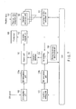
- FIG. 5 is a flowchart showing the processing sequence of the energy management server 4 according to the first embodiment.
- the energy management server 4 accepts a setting of a virtual DR condition and designation of a reducible amount by the user (step S1, step S2). After these pieces of information are input, DR formulation units 103a and 103b formulate suppression conditions respectively included in a DR signal and virtual DR signal, and pass the formulas to the scheduling unit 104 (step S3).
- the energy management server 4 provides received weather data (step S4) to the demand estimation unit 101.
- the demand estimation unit 101 estimates a power demand and heat demand based on the weather data and data of the controlled apparatuses 2 (step S5). This estimation result is input to the scheduling unit 104, which generates an operation schedule of the controlled apparatuses 2.
- an operation schedule based on a virtual DR signal is calculated.
- the calculated operation schedule is stored in the operation database 108. Note that the sequence of steps S1 to S6 can be repeated many times by changing a virtual DR condition.
- the DR reception unit 102 waits for arrival of an external DR signal (step S7, step S8). If the DR reception unit 102 cannot confirm arrival of a DR signal (No in step S8), it confirms a DR signal again after an elapse of a prescribed time. If reception of a DR signal can be confirmed, the energy management server 4 executes an operation schedule prepared in advance based on a suppression condition included in the received DR signal (step S9).
- step S9 an operation schedule has already been calculated under a suppression condition which matches or is close to that included in the received DR signal. Therefore, the energy management server 4 can start execution of an operation schedule corresponding to a suppression condition immediately after reception of a DR signal.
- virtual DR signals that is, pieces of information which imitate various energy suppression conditions are provided for the energy management server 4.
- the energy management server 4 generates a plurality of operation schedules based on virtual DR signals before arrival of a DR signal.
- a plurality of scenarios that assume every DR signals can be set and generated in advance. Therefore, a time required to determine advisability of an operation schedule used in actual operations and a setting time required to generate an operation schedule can be assured.
- the controlled apparatuses 2 upon reception of a DR signal, the controlled apparatuses 2 can be immediately controlled based on the already calculated operation schedule.
- a lead time until the beginning of activation of especially an apparatus which is difficult to be quickly activated such as a heat energy related apparatus can be shortened.
- the controlled apparatuses 2 can be activated under maximally advantageous conditions.
- an energy management server, energy management method, and program which can immediately start control based on an advantageous operation schedule in response to reception of a demand response signal can be provided.
- FIG. 6 is a functional block diagram showing an example of an energy management server 4 according to the second embodiment.
- the same reference numbers denote parts common to FIG. 3 , and only different parts will be described in this embodiment.
- a program memory 45 includes an estimation condition selection program 111P and selection support program 112P. These programs implement functions of an estimation condition selection unit 111 and selection support unit 112 in a CPU 44.
- the estimation condition selection unit 111 is an interface which prompts the user to select a desired demand estimation from a plurality of energy demand estimations.
- the selection support unit 112 is an interface which prompts the user to select one operation schedule to be executed from a plurality of operation schedules output from a scheduling unit 104.
- FIG. 7 shows the data flows among the function blocks shown in FIG. 6 .
- a plurality of demand estimation units 101 shown in FIG. 7 have similar function as in the first embodiment.
- weather data received by a weather data reception unit 107 is passed to the demand estimation units 101.
- the demand estimation units 101 calculate a plurality of energy demand estimations based on different criteria on the basis of the weather data and data of controlled apparatuses 2. For example, by applying a technique for calculating a demand estimation by a learning function of a computer, different data sets are used as data to be learned, thereby obtaining different demand estimation results for the same weather data.
- a predicted mean vote as a comfort evaluation index associated with air-conditioning control can be used.
- the PMV is specified by ISO 7730, and is a value calculated from a temperature, humidity, wind velocity, amount of clothing, radiation temperature, and amount of activity. When the PMV value falls within a range of ⁇ 0.5, about 90% persons feel comfort. As the PMV value is larger, people feel hotter; as the value is smaller, people feel colder.
- the demand estimation units 101 calculates energy demand estimations for respective data sets. These demand estimations are supplied to the estimation condition selection unit 111.
- the estimation condition selection unit 111 displays these plurality of demand estimations on a GUI in a menu form or the like, and prompts the user to make, for example, a selection operation such as a click operation. At least one selected demand estimation is passed to the scheduling unit 104, and an operation schedule is calculated in the same manner as in the first embodiment. Note that both an operation schedule which considers a virtual DR signal and that which does not consider any DR signal may be calculated. The calculated operation schedule is stored in an operation database 108.
- a formula which expresses a suppression condition included in this DR signal is passed to a search unit 110.
- the search unit 110 searches the operation database 108 based on this formula, and acquires operation schedules calculated under a virtual DR condition which reflects this formula for a plurality of estimation conditions.
- the acquired operation schedules for respective estimation conditions are passed to the selection support unit 112.
- the selection support unit 112 displays the operation schedules for respective estimation conditions on the GUI.
- the operation schedule selected by the user is passed to a control unit 109.
- the control unit 109 controls the controlled apparatuses 2 based on the schedule of the user's choice.
- FIG. 8 is a flowchart showing the processing sequence of the energy management server 4 according to the second embodiment.
- the same step numbers denote processes common to FIG. 5 , and only different processes will be described in this embodiment.
- the estimation condition selection unit 111 displays the calculated demand estimations on the GUI, and waits for user's selection (step S10). If the user selects one demand condition, an operation schedule is calculated based on the selected demand estimation (step S6). The processes of steps S5, S10, and S6 are repeated until the user's selection operations are complete, that is, until a completion instruction of all cases is input (Yes in step S11).
- FIG. 9 shows an example of a schedule selection screen displayed on the GUI according to the second embodiment. This screen is displayed on a display 42 in step S12 of FIG. 8 . Two different operation schedules are displayed on the right and left sides of the screen. Operation buttons 201 and 202 having different signs are displayed in association with the operation schedules.
- the schedule corresponding to the operation button 201 considers a DR signal, and that corresponding to the operation button 202 does not consider any DR signal. Note that a plurality of schedules which consider DR signals may be displayed in correspondence with a plurality of demand estimations in some cases. However, FIG. 9 shows only one schedule.
- Each operation schedule represents the relationship between heat storage and heat dissipation energy amounts, and received power amounts.
- the user who prioritizes a cost reduction selects the left schedule, and clicks the operation button 201 to inform the system of his or her intention.
- control based on the operation schedule which considers DR is started.
- peaks of received power amounts for respective schedules are displayed together.
- a peak power of the left schedule is 620 kW, and that of the right schedule is 900 kW.
- this numerical value can be used as a reference.
- the cost and peak power displayed on this screen are assumed values when the corresponding operation is executed, and are calculation values calculated by the scheduling unit 104.
- a plurality of operation schedules are calculated, and are presented to the user.
- the plurality of operation schedules can include a schedule in a normal operation state which does not assume a DR signal, and that which assumes arrival of a DR signal.
- the plurality of operation schedules can include a plurality of schedules corresponding to a plurality of energy demand estimations based on a plurality of criteria. The user can select one of the presented operation schedules and, hence, the user's intention can be reflected to control of the controlled apparatuses 2.
- FIG. 10 shows another example of the data flows among the function blocks shown in FIG. 3 .
- FIG. 10 shows the DR formulation unit 103, which is shown as DR formulation units 103a and 103b in FIG. 4 , as one object (thread).
- This DR formulation unit 103 assumes two processes of formulation of a suppression condition included in an actual DR signal, and that of a suppression condition included in a virtual DR signal. Hence, the actual DR signal and virtual DR signal can be distinguished from each other using, for example, a flag.
- a DR signal without any flag indicating a virtual DR signal is handled as an actual DR signal, and a formula which represents its suppression condition is passed to the search unit 110.
- a DR signal with the flag indicating a virtual DR signal is handled as a virtual DR signal, and a formula which represents its suppression condition is passed to the scheduling unit 104. In this manner, the same operations as in the first embodiment can be attained.
- At least any of the demand estimation unit 101, DR reception unit 102, DR formulation unit 103, scheduling unit 104, condition setting unit 105, reducible amount designation unit 106, weather data reception unit 107, operation database 108, control unit 109, search unit 110, condition selection unit 111, and selection support unit 112 may be implemented on a cloud computing system.
- Programs which implement the functions of these function blocks may be installed in a single computer or may be installed while being distributed to a plurality of computers. How to implement these function objects in a system can be understood by those who are skilled in the art.
Landscapes
- Engineering & Computer Science (AREA)
- Business, Economics & Management (AREA)
- Human Resources & Organizations (AREA)
- Entrepreneurship & Innovation (AREA)
- Power Engineering (AREA)
- Economics (AREA)
- Strategic Management (AREA)
- Physics & Mathematics (AREA)
- General Physics & Mathematics (AREA)
- Educational Administration (AREA)
- Marketing (AREA)
- Operations Research (AREA)
- Quality & Reliability (AREA)
- Tourism & Hospitality (AREA)
- Development Economics (AREA)
- General Business, Economics & Management (AREA)
- Theoretical Computer Science (AREA)
- Game Theory and Decision Science (AREA)
- Automation & Control Theory (AREA)
- General Engineering & Computer Science (AREA)
- Supply And Distribution Of Alternating Current (AREA)
- Management, Administration, Business Operations System, And Electronic Commerce (AREA)
- Remote Monitoring And Control Of Power-Distribution Networks (AREA)
- Health & Medical Sciences (AREA)
- Artificial Intelligence (AREA)
- Computer Vision & Pattern Recognition (AREA)
- Evolutionary Computation (AREA)
- Medical Informatics (AREA)
- Software Systems (AREA)
Applications Claiming Priority (2)
| Application Number | Priority Date | Filing Date | Title |
|---|---|---|---|
| JP2012270349A JP6109555B2 (ja) | 2012-12-11 | 2012-12-11 | エネルギー管理サーバ、エネルギー管理方法およびプログラム |
| PCT/JP2013/067707 WO2014091784A1 (fr) | 2012-12-11 | 2013-06-27 | Serveur de gestion d'énergie, procédé de gestion d'énergie, et programme |
Publications (2)
| Publication Number | Publication Date |
|---|---|
| EP2933774A1 true EP2933774A1 (fr) | 2015-10-21 |
| EP2933774A4 EP2933774A4 (fr) | 2016-04-20 |
Family
ID=50934087
Family Applications (1)
| Application Number | Title | Priority Date | Filing Date |
|---|---|---|---|
| EP13815667.4A Withdrawn EP2933774A4 (fr) | 2012-12-11 | 2013-06-27 | Serveur de gestion d'énergie, procédé de gestion d'énergie, et programme |
Country Status (5)
| Country | Link |
|---|---|
| US (1) | US10345766B2 (fr) |
| EP (1) | EP2933774A4 (fr) |
| JP (1) | JP6109555B2 (fr) |
| CN (1) | CN103999114B (fr) |
| WO (1) | WO2014091784A1 (fr) |
Families Citing this family (18)
| Publication number | Priority date | Publication date | Assignee | Title |
|---|---|---|---|---|
| JP6180826B2 (ja) * | 2013-07-02 | 2017-08-16 | 株式会社東芝 | エネルギー管理サーバ、エネルギー管理方法およびプログラム |
| JP6139306B2 (ja) | 2013-07-10 | 2017-05-31 | 株式会社東芝 | 運転計画最適化装置、運転計画最適化方法及び運転計画最適化プログラム |
| SG11201500154YA (en) | 2013-09-11 | 2015-04-29 | Toshiba Kk | Battery controller, management system, battery control method, battery control program, and storage medium |
| JP6356502B2 (ja) | 2014-06-20 | 2018-07-11 | 株式会社東芝 | 機器運転設定装置及び機器運転設定値決定プログラム |
| JP5967265B2 (ja) | 2014-07-31 | 2016-08-10 | ダイキン工業株式会社 | 機器制御装置 |
| JP6038085B2 (ja) * | 2014-08-28 | 2016-12-07 | 横河電機株式会社 | 産業用デマンドレスポンス制御システムおよび産業用デマンドレスポンス制御方法 |
| JP6296966B2 (ja) * | 2014-12-03 | 2018-03-20 | 三菱電機株式会社 | 需給調整装置 |
| KR101698264B1 (ko) * | 2015-03-11 | 2017-01-19 | 엘지전자 주식회사 | 네트워크 시스템 및 그 제어방법 |
| JP6562664B2 (ja) * | 2015-03-13 | 2019-08-21 | 株式会社日立製作所 | エネルギー制御システム |
| KR102586745B1 (ko) | 2015-09-01 | 2023-10-10 | 삼성전자 주식회사 | 에너지 소비를 관리하는 방법 및 장치 |
| US10387926B2 (en) * | 2015-10-30 | 2019-08-20 | Global Design Corporation Ltd. | Cloud-based methods for identifying energy profile and estimating energy consumption and cloud-based energy profile usage identification system |
| EP3726307A1 (fr) | 2019-04-17 | 2020-10-21 | Carrier Corporation | Procédé de régulation de la consommation d'énergie de construction |
| JP7140716B2 (ja) * | 2019-06-17 | 2022-09-21 | トヨタ紡織株式会社 | エネルギー管理システム及びエネルギー管理方法 |
| CN113608486B (zh) * | 2021-08-20 | 2024-10-15 | 沈阳世杰电器有限公司 | 利用现有电网的分布式负荷设备集中控制系统及方法 |
| KR102744374B1 (ko) * | 2022-02-08 | 2024-12-19 | 한국전력기술 주식회사 | 건물 에너지 제어 시스템 |
| JP2023177474A (ja) * | 2022-06-02 | 2023-12-14 | 株式会社日立製作所 | 電力管理システム及び電力管理方法 |
| CN115222161B (zh) * | 2022-09-19 | 2022-12-09 | 国网浙江省电力有限公司宁波供电公司 | 用于管理电动车辆的需求响应的方法、装置及介质 |
| JP2024154821A (ja) * | 2023-04-20 | 2024-10-31 | 株式会社日立製作所 | 電気料金計画システム及び電気料金計画方法 |
Family Cites Families (58)
| Publication number | Priority date | Publication date | Assignee | Title |
|---|---|---|---|---|
| US20030189420A1 (en) * | 2001-09-28 | 2003-10-09 | Hiroyuki Hashimoto | Method for assisting in planning of power supply schedule |
| JP4369189B2 (ja) * | 2003-09-22 | 2009-11-18 | 三菱電機株式会社 | スケジューリングシステムおよびスケジューリングをコンピュータに実行させるためのプログラム |
| JP2005157685A (ja) | 2003-11-25 | 2005-06-16 | Toshiba Corp | エネルギー需要予測システム |
| JP2005257097A (ja) | 2004-03-09 | 2005-09-22 | Toshiba Corp | 熱源機器の起動停止計画策定システム |
| JP2006098361A (ja) | 2004-09-30 | 2006-04-13 | Toshiba Corp | 建物エネルギー監視評価装置 |
| JP4396557B2 (ja) | 2005-03-22 | 2010-01-13 | 株式会社日立プラントテクノロジー | 空調システム |
| WO2008009458A1 (fr) * | 2006-07-21 | 2008-01-24 | Novartis Ag | Composés de 2,4-di(arylamino)-pyrimidine-5-carboxamide comme inhibiteurs des jak kinases |
| JP5199694B2 (ja) * | 2007-02-19 | 2013-05-15 | パナソニック株式会社 | スケジュール生成装置 |
| JP5011028B2 (ja) * | 2007-08-23 | 2012-08-29 | 株式会社日立製作所 | ストレージシステム、管理装置、スケジューリング方法、プログラム、記録媒体 |
| JP4796557B2 (ja) | 2007-08-30 | 2011-10-19 | 富士フイルム株式会社 | 撮影装置 |
| US20100017045A1 (en) * | 2007-11-30 | 2010-01-21 | Johnson Controls Technology Company | Electrical demand response using energy storage in vehicles and buildings |
| JP2009245378A (ja) * | 2008-03-31 | 2009-10-22 | Toshiba Corp | 情報処理装置 |
| US8239073B2 (en) * | 2008-04-17 | 2012-08-07 | Asoka Usa Corporation | Systems and methods for controlling energy consumption |
| US20100332373A1 (en) | 2009-02-26 | 2010-12-30 | Jason Crabtree | System and method for participation in energy-related markets |
| US20100218108A1 (en) | 2009-02-26 | 2010-08-26 | Jason Crabtree | System and method for trading complex energy securities |
| US20110040666A1 (en) | 2009-08-17 | 2011-02-17 | Jason Crabtree | Dynamic pricing system and method for complex energy securities |
| US20100217550A1 (en) | 2009-02-26 | 2010-08-26 | Jason Crabtree | System and method for electric grid utilization and optimization |
| US9753455B2 (en) | 2009-06-22 | 2017-09-05 | Johnson Controls Technology Company | Building management system with fault analysis |
| US9196009B2 (en) | 2009-06-22 | 2015-11-24 | Johnson Controls Technology Company | Systems and methods for detecting changes in energy usage in a building |
| US9286582B2 (en) | 2009-06-22 | 2016-03-15 | Johnson Controls Technology Company | Systems and methods for detecting changes in energy usage in a building |
| US9606520B2 (en) | 2009-06-22 | 2017-03-28 | Johnson Controls Technology Company | Automated fault detection and diagnostics in a building management system |
| US8600556B2 (en) * | 2009-06-22 | 2013-12-03 | Johnson Controls Technology Company | Smart building manager |
| US8532839B2 (en) | 2009-06-22 | 2013-09-10 | Johnson Controls Technology Company | Systems and methods for statistical control and fault detection in a building management system |
| US8788097B2 (en) | 2009-06-22 | 2014-07-22 | Johnson Controls Technology Company | Systems and methods for using rule-based fault detection in a building management system |
| US8731724B2 (en) | 2009-06-22 | 2014-05-20 | Johnson Controls Technology Company | Automated fault detection and diagnostics in a building management system |
| US8156683B2 (en) | 2009-07-09 | 2012-04-17 | David Slotnick | Wireless rat trap movement detection system |
| EP2457132B1 (fr) | 2009-07-20 | 2019-06-26 | Samsung Electronics Co., Ltd. | Système de gestion d énergie |
| US8855830B2 (en) | 2009-08-21 | 2014-10-07 | Allure Energy, Inc. | Energy management system and method |
| US9209652B2 (en) | 2009-08-21 | 2015-12-08 | Allure Energy, Inc. | Mobile device with scalable map interface for zone based energy management |
| US8498749B2 (en) | 2009-08-21 | 2013-07-30 | Allure Energy, Inc. | Method for zone based energy management system with scalable map interface |
| US9838255B2 (en) | 2009-08-21 | 2017-12-05 | Samsung Electronics Co., Ltd. | Mobile demand response energy management system with proximity control |
| JP4806059B2 (ja) | 2009-09-09 | 2011-11-02 | 株式会社東芝 | エネルギー管理システムおよびエネルギー管理方法 |
| JP5127799B2 (ja) * | 2009-09-10 | 2013-01-23 | 株式会社東芝 | 電力デマンド監視装置および電力デマンド監視方法 |
| US9159108B2 (en) | 2009-10-23 | 2015-10-13 | Viridity Energy, Inc. | Facilitating revenue generation from wholesale electricity markets |
| US9159042B2 (en) | 2009-10-23 | 2015-10-13 | Viridity Energy, Inc. | Facilitating revenue generation from data shifting by data centers |
| US8892264B2 (en) | 2009-10-23 | 2014-11-18 | Viridity Energy, Inc. | Methods, apparatus and systems for managing energy assets |
| US20130245847A1 (en) | 2009-10-23 | 2013-09-19 | Alain P. Steven | Facilitating revenue generation from wholesale electricity markets using an enineering-based energy asset model |
| US8457802B1 (en) | 2009-10-23 | 2013-06-04 | Viridity Energy, Inc. | System and method for energy management |
| US9367825B2 (en) | 2009-10-23 | 2016-06-14 | Viridity Energy, Inc. | Facilitating revenue generation from wholesale electricity markets based on a self-tuning energy asset model |
| US9491005B2 (en) * | 2009-11-26 | 2016-11-08 | Lg Electronics Inc. | Network system and method of controlling network system |
| JP5645244B2 (ja) * | 2010-02-05 | 2014-12-24 | パナソニックIpマネジメント株式会社 | エネルギー需給制御システム |
| WO2011100255A2 (fr) | 2010-02-09 | 2011-08-18 | Johnson Controls Technology Company | Systèmes et procédés permettant de mesurer et de vérifier les économies d'énergie dans des bâtiments |
| JP2011179722A (ja) | 2010-02-26 | 2011-09-15 | Toshiba Corp | 空調制御システム |
| JP5646205B2 (ja) | 2010-04-28 | 2014-12-24 | 株式会社東芝 | 消費電力管理システム、およびこれに利用される消費電力管理装置、消費電力管理方法、中央供給電力管理装置、供給電力管理方法 |
| JP4995958B2 (ja) * | 2010-09-16 | 2012-08-08 | 株式会社東芝 | 消費エネルギー算出装置 |
| WO2012044946A2 (fr) * | 2010-10-01 | 2012-04-05 | Drexel University | Modélisation de la charge dynamique de la consommation d'énergie d'un bâtiment pour les applications de réponse à la demande |
| JP2012094077A (ja) * | 2010-10-28 | 2012-05-17 | Toshiba Corp | 家庭用エネルギー管理システム |
| JP5300829B2 (ja) * | 2010-11-30 | 2013-09-25 | 三菱電機株式会社 | 住宅電気エネルギー管理装置、住宅電気エネルギー管理システム、住宅電気エネルギー管理方法、および、プログラム |
| JP5679847B2 (ja) * | 2011-02-04 | 2015-03-04 | 株式会社東芝 | エネルギー管理システムおよびエネルギー管理方法 |
| US8387729B2 (en) * | 2011-03-10 | 2013-03-05 | Caterpillar Inc. | Machine having electrical power system and centered drive coupling for same |
| WO2012137814A1 (fr) * | 2011-04-04 | 2012-10-11 | シャープ株式会社 | Contrôleur et procédé de commande |
| JP5837322B2 (ja) * | 2011-04-18 | 2015-12-24 | 京セラ株式会社 | 制御装置、電力制御システム、及び電力制御方法 |
| JP5784352B2 (ja) * | 2011-04-22 | 2015-09-24 | トヨタホーム株式会社 | 住宅エネルギーシステム |
| JP5316610B2 (ja) * | 2011-08-03 | 2013-10-16 | ダイキン工業株式会社 | 電気機器の制御装置および制御システム |
| US20130038820A1 (en) | 2011-10-28 | 2013-02-14 | Shi-Chiung Chen | Micro structure substrates for flexible display device and methods of manufacturing the same |
| US20130038379A1 (en) | 2011-10-28 | 2013-02-14 | Shi-Chiung Chen | Micro structure substrates for sensor panels |
| JP5743881B2 (ja) | 2011-12-28 | 2015-07-01 | 株式会社東芝 | 電力管理システム、電力管理方法、需要家端末及び電力管理装置 |
| US9879872B2 (en) * | 2012-06-15 | 2018-01-30 | Mitsubishi Electric Corporation | Air-conditioning management device, air-conditioning management method, and program |
-
2012
- 2012-12-11 JP JP2012270349A patent/JP6109555B2/ja not_active Expired - Fee Related
-
2013
- 2013-06-27 WO PCT/JP2013/067707 patent/WO2014091784A1/fr not_active Ceased
- 2013-06-27 CN CN201380001897.3A patent/CN103999114B/zh not_active Expired - Fee Related
- 2013-06-27 EP EP13815667.4A patent/EP2933774A4/fr not_active Withdrawn
- 2013-09-12 US US14/025,042 patent/US10345766B2/en active Active
Also Published As
| Publication number | Publication date |
|---|---|
| EP2933774A4 (fr) | 2016-04-20 |
| JP6109555B2 (ja) | 2017-04-05 |
| US20140163757A1 (en) | 2014-06-12 |
| WO2014091784A1 (fr) | 2014-06-19 |
| CN103999114A (zh) | 2014-08-20 |
| JP2014115878A (ja) | 2014-06-26 |
| US10345766B2 (en) | 2019-07-09 |
| CN103999114B (zh) | 2017-12-05 |
Similar Documents
| Publication | Publication Date | Title |
|---|---|---|
| EP2933774A1 (fr) | Serveur de gestion d'énergie, procédé de gestion d'énergie, et programme | |
| US9559549B2 (en) | Energy management server, energy management method, and program | |
| US9310792B2 (en) | Scheduling and modeling the operation of controllable and non-controllable electronic devices | |
| Wang et al. | Multi-agent control system with intelligent optimization for smart and energy-efficient buildings | |
| US9691076B2 (en) | Demand response system having a participation predictor | |
| US8676394B2 (en) | Integrated demand response for energy utilization | |
| Sivaneasan et al. | Preemptive demand response management for buildings | |
| Wu et al. | Stochastic optimal scheduling of residential appliances with renewable energy sources | |
| CN112036934A (zh) | 考虑热电协调运行的负荷聚合商参与需求响应的报价方法 | |
| Liang et al. | Safe reinforcement learning-based resilient proactive scheduling for a commercial building considering correlated demand response | |
| Mohammadi et al. | A multi-objective fuzzy optimization model for electricity generation and consumption management in a micro smart grid | |
| US20160084889A1 (en) | System and method for stability monitoring, analysis and control of electric power systems | |
| US20190050015A1 (en) | System and method for stability monitoring, analysis and control of electric power systems | |
| Tsaousoglou et al. | Multistage energy management of coordinated smart buildings: A multiagent Markov decision process approach | |
| Ozawa et al. | Data-driven HVAC control using symbolic regression: design and implementation | |
| Lee et al. | A genetic algorithm based power consumption scheduling in smart grid buildings | |
| US10095256B2 (en) | Power control device, method, and program based on evaluation functions regarding upper limit amount of power | |
| Friansa et al. | Enhancing university building energy flexibility performance using reinforcement learning control | |
| Wang et al. | Customer-centered control system for intelligent and green building with heuristic optimization | |
| Sankur et al. | An architecture for integrated commercial building demand response | |
| CN110535143A (zh) | 面向智能住宅动态需求响应的能源管理方法和装置 | |
| Paré et al. | Efficient data-driven model predictive control for demand response of commercial buildings | |
| JP2018207709A (ja) | 表示処理装置、表示処理方法および表示処理プログラム | |
| JP2016116424A (ja) | 需要家装置、電力消費管理装置、電力消費管理システム、電力消費管理方法および電力消費管理プログラム | |
| Fagiani et al. | A new open-source energy management framework: Functional description and preliminary results |
Legal Events
| Date | Code | Title | Description |
|---|---|---|---|
| PUAI | Public reference made under article 153(3) epc to a published international application that has entered the european phase |
Free format text: ORIGINAL CODE: 0009012 |
|
| 17P | Request for examination filed |
Effective date: 20140118 |
|
| AK | Designated contracting states |
Kind code of ref document: A1 Designated state(s): AL AT BE BG CH CY CZ DE DK EE ES FI FR GB GR HR HU IE IS IT LI LT LU LV MC MK MT NL NO PL PT RO RS SE SI SK SM TR |
|
| AX | Request for extension of the european patent |
Extension state: BA ME |
|
| DAX | Request for extension of the european patent (deleted) | ||
| A4 | Supplementary search report drawn up and despatched |
Effective date: 20160322 |
|
| RIC1 | Information provided on ipc code assigned before grant |
Ipc: H02J 3/00 20060101ALI20160316BHEP Ipc: G06Q 50/06 20120101AFI20160316BHEP |
|
| STAA | Information on the status of an ep patent application or granted ep patent |
Free format text: STATUS: EXAMINATION IS IN PROGRESS |
|
| 17Q | First examination report despatched |
Effective date: 20180125 |
|
| STAA | Information on the status of an ep patent application or granted ep patent |
Free format text: STATUS: THE APPLICATION HAS BEEN WITHDRAWN |
|
| 18W | Application withdrawn |
Effective date: 20190816 |