EP2934049B1 - Verfahren und vorrichtung zur erfassung einer uplink-synchronisation in einem drahtlosen zugangssystem mit trägeraggregationsunterstützung - Google Patents
Verfahren und vorrichtung zur erfassung einer uplink-synchronisation in einem drahtlosen zugangssystem mit trägeraggregationsunterstützung Download PDFInfo
- Publication number
- EP2934049B1 EP2934049B1 EP13863524.8A EP13863524A EP2934049B1 EP 2934049 B1 EP2934049 B1 EP 2934049B1 EP 13863524 A EP13863524 A EP 13863524A EP 2934049 B1 EP2934049 B1 EP 2934049B1
- Authority
- EP
- European Patent Office
- Prior art keywords
- scell
- random access
- rach
- information
- access procedure
- Prior art date
- Legal status (The legal status is an assumption and is not a legal conclusion. Google has not performed a legal analysis and makes no representation as to the accuracy of the status listed.)
- Active
Links
Images






Classifications
-
- H—ELECTRICITY
- H04—ELECTRIC COMMUNICATION TECHNIQUE
- H04W—WIRELESS COMMUNICATION NETWORKS
- H04W74/00—Wireless channel access
- H04W74/08—Non-scheduled access, e.g. ALOHA
-
- H—ELECTRICITY
- H04—ELECTRIC COMMUNICATION TECHNIQUE
- H04W—WIRELESS COMMUNICATION NETWORKS
- H04W72/00—Local resource management
- H04W72/20—Control channels or signalling for resource management
- H04W72/23—Control channels or signalling for resource management in the downlink direction of a wireless link, i.e. towards a terminal
-
- H—ELECTRICITY
- H04—ELECTRIC COMMUNICATION TECHNIQUE
- H04J—MULTIPLEX COMMUNICATION
- H04J11/00—Orthogonal multiplex systems, e.g. using WALSH codes
- H04J11/0069—Cell search, i.e. determining cell identity [cell-ID]
- H04J11/0073—Acquisition of primary synchronisation channel, e.g. detection of cell-ID within cell-ID group
-
- H—ELECTRICITY
- H04—ELECTRIC COMMUNICATION TECHNIQUE
- H04L—TRANSMISSION OF DIGITAL INFORMATION, e.g. TELEGRAPHIC COMMUNICATION
- H04L5/00—Arrangements affording multiple use of the transmission path
- H04L5/003—Arrangements for allocating sub-channels of the transmission path
- H04L5/0032—Distributed allocation, i.e. involving a plurality of allocating devices, each making partial allocation
-
- H—ELECTRICITY
- H04—ELECTRIC COMMUNICATION TECHNIQUE
- H04W—WIRELESS COMMUNICATION NETWORKS
- H04W28/00—Network traffic management; Network resource management
- H04W28/16—Central resource management; Negotiation of resources or communication parameters, e.g. negotiating bandwidth or QoS [Quality of Service]
- H04W28/18—Negotiating wireless communication parameters
-
- H—ELECTRICITY
- H04—ELECTRIC COMMUNICATION TECHNIQUE
- H04W—WIRELESS COMMUNICATION NETWORKS
- H04W56/00—Synchronisation arrangements
- H04W56/0005—Synchronisation arrangements synchronizing of arrival of multiple uplinks
-
- H—ELECTRICITY
- H04—ELECTRIC COMMUNICATION TECHNIQUE
- H04W—WIRELESS COMMUNICATION NETWORKS
- H04W56/00—Synchronisation arrangements
- H04W56/0055—Synchronisation arrangements determining timing error of reception due to propagation delay
-
- H—ELECTRICITY
- H04—ELECTRIC COMMUNICATION TECHNIQUE
- H04J—MULTIPLEX COMMUNICATION
- H04J11/00—Orthogonal multiplex systems, e.g. using WALSH codes
- H04J2011/0096—Network synchronisation
Definitions
- the present invention relates to a wireless access system supporting Carrier Aggregation (CA), and more particularly, to a method for acquiring uplink synchronization and an apparatus supporting the same.
- CA Carrier Aggregation
- Wireless access systems have been widely deployed to provide various types of communication services such as voice or data.
- a wireless access system is a multiple access system that supports communication of multiple users by sharing available system resources (a bandwidth, transmission power, etc.) among them.
- multiple access systems include a Code Division Multiple Access (CDMA) system, a Frequency Division Multiple Access (FDMA) system, a Time Division Multiple Access (TDMA) system, an Orthogonal Frequency Division Multiple Access (OFDMA) system, and a Single Carrier Frequency Division Multiple Access (SC-FDMA) system.
- CDMA Code Division Multiple Access
- FDMA Frequency Division Multiple Access
- TDMA Time Division Multiple Access
- OFDMA Orthogonal Frequency Division Multiple Access
- SC-FDMA Single Carrier Frequency Division Multiple Access
- Document WO2013/139308 A1 relates to methods for physical layer multi-point carrier aggregation and multi-point feed-back configuration.
- Document US2012/300714 A1 relates to methods and apparatus for random access procedures with carrier aggregation for lte-advanced systems.
- An object of the present invention devised to solve the problem lies on a method for acquiring uplink synchronization in a situation in which a plurality of cells are aggregated.
- Another object of the present invention is to provide a method for acquiring uplink synchronization with a Secondary Cell (SCell) to be added in a CA environment.
- SCell Secondary Cell
- Another object of the present invention is to provide a method for acquiring uplink synchronization with a geographically spaced SCell in a CA environment.
- Another object of the present invention is to provide apparatuses supporting the above methods.
- the present invention relates to a wireless access system supporting Carrier Aggregation (CA), and more particularly, to a method for acquiring uplink synchronization with two or more geographically spaced cells and an apparatus supporting the same.
- CA Carrier Aggregation
- a method for acquiring uplink synchronization in a wireless access system supporting Carrier Aggregation includes receiving from a Primacy Cell (PCell) Random Access Channel (RACH) information related to a first random access procedure for acquiring uplink synchronization with a Secondary Cell (SCell) to be added to the CA, and performing the first random access procedure for acquiring uplink synchronization with the SCell, based on the RACH information.
- the RACH information includes resource allocation information and an RACH parameter, the resource allocation information indicating a resource area of the SCell in which the first random access procedure is to be performed and the RACH parameter being needed for generating an RACH preamble to be used in the first random access procedure.
- the SCell may be geographically spaced from the PCell.
- the RACH information may be system information used in the SCell.
- the method may further include receiving from the PCell a Physical Downlink Control Channel (PDCCH) order message indicating execution of a second random access procedure for acquiring uplink synchronization, and performing the second random access procedure with at least one of the PCell and the SCell, indicated by the PDCCH order message.
- the PDCCH order message may include information indicating a cell with which the second random access procedure is to be performed.
- the SCell may be a leader SCell of a SCell group.
- the random access procedure may be a contention-based initial random access procedure.
- a method for supporting acquisition of uplink synchronization in a wireless access system supporting CA includes negotiating RACH information related to a first random access procedure for acquiring uplink synchronization with a SCell to be added to the CA with the SCell by a PCell, acquiring RACH information including resource allocation information and an RACH parameter by the negotiation, the resource allocation information indicating a resource area of the SCell in which the first random access procedure is to be performed and the RACH parameter being needed for generating an RACH preamble to be used in the first random access procedure, and transmitting the RACH information to a UE.
- the SCell may be geographically spaced from the PCell.
- the RACH information may be system information used in the SCell.
- the method may further include transmitting to the UE a PDCCH order message indicating execution of a second random access procedure for acquiring uplink synchronization, and the PDCCH order message may include information indicating a cell with which the second random access procedure is to be performed.
- the SCell may be a leader SCell of a SCell group.
- the random access procedure may be a contention-based initial random access procedure.
- a UE for acquiring uplink synchronization in a wireless access system supporting CA includes a transmitter, a receiver, and a processor configured to support acquisition of uplink synchronization.
- the processor is configured to receive from a PCell RACH information related to a first random access procedure for acquiring uplink synchronization with a SCell to be added to the CA by controlling the receiver, and to perform the first random access procedure for acquiring uplink synchronization with the SCell based on the RACH information by controlling the transmitter and the receiver, and the RACH information includes resource allocation information and an RACH parameter, the resource allocation information indicating a resource area of the SCell in which the first random access procedure is to be performed and the RACH parameter being needed for generating an RACH preamble to be used in the first random access procedure.
- the SCell may be geographically spaced from the PCell.
- the RACH information may be system information used in the SCell.
- the processor may be configured to receive a PDCCH order message indicating execution of a second random access procedure for acquiring uplink synchronization from the PCell through the receiver, and to perform the second random access procedure with at least one of the PCell and the SCell indicated by the PDCCH order message by controlling the receiver and the transmitter.
- the PDCCH order message may include information indicating a cell with which the second random access procedure is to be performed.
- the SCell may be a leader SCell of a SCell group.
- the random access procedure may be a contention-based initial random access procedure.
- a Base Station (BS) for supporting acquisition of uplink synchronization in a wireless access system supporting CA includes a transmitter, a receiver, and a processor configured to support acquisition of uplink synchronization.
- the processor is configured to negotiate RACH information related to a first random access procedure for acquiring uplink synchronization with a SCell to be added to the CA with the SCell by a PCell of the BS by controlling the transmitter and the receiver, to acquire RACH information including resource allocation information and an RACH parameter by the negotiation, the resource allocation information indicating a resource area of the SCell in which the first random access procedure is to be performed and the RACH parameter being needed for generating an RACH preamble to be used in the first random access procedure, and to transmit the RACH information to a UE by controlling the transmitter.
- the SCell may be geographically spaced from the PCell.
- the RACH information may be system information used in the SCell.
- the processor may be configured to transmit to the UE a PDCCH order message indicating execution of a second random access procedure for acquiring uplink synchronization by controlling the transmitter.
- the PDCCH order message may include information indicating a cell with which the second random access procedure is to be performed.
- the SCell may be a leader SCell of a SCell group.
- the random access procedure may be a contention-based initial random access procedure.
- uplink synchronization can be acquired fast in a situation in which a plurality of cells are aggregated.
- uplink synchronization with a Secondary Cell (SCell) to be added can be acquired in a CA environment.
- SCell Secondary Cell
- uplink synchronization with a geographically spaced SCell can be acquired in a CA environment.
- a Random Access Channel (RACH) procedure can be performed fast with a SCell by acquiring RACH information about the SCell from a Primary Cell (PCell) in advance.
- RACH Random Access Channel
- Embodiments of the present invention described below in detail are used in a wireless access system supporting Carrier Aggregation (CA) and provide a method for acquiring uplink synchronization with two or more geographically spaced cells and an apparatus supporting the same.
- CA Carrier Aggregation
- a BS refers to a terminal node of a network, which directly communicates with a UE.
- a specific operation described as being performed by the BS may be performed by an upper node of the BS.
- a network comprised of a plurality of network nodes including a BS
- various operations performed for communication with a UE may be performed by the BS, or network nodes other than the BS.
- the term 'BS' may be replaced with a fixed station, a Node B, an evolved Node B (eNode B or eNB), an Advanced Base Station (ABS), an access point, etc.
- the term terminal may be replaced with a UE, a Mobile Station (MS), a Subscriber Station (SS), a Mobile Subscriber Station (MSS), a mobile terminal, an Advanced Mobile Station (AMS), etc.
- MS Mobile Station
- SS Subscriber Station
- MSS Mobile Subscriber Station
- AMS Advanced Mobile Station
- a transmitter is a fixed and/or mobile node that provides a data service or a voice service and a receiver is a fixed and/or mobile node that receives a data service or a voice service. Therefore, a UE may serve as a transmitter and a BS may serve as a receiver, on an UpLink (UL). Likewise, the UE may serve as a receiver and the BS may serve as a transmitter, on a DownLink (DL).
- UL UpLink
- DL DownLink
- the embodiments of the present invention may be supported by standard specifications disclosed for at least one of wireless access systems including an Institute of Electrical and Electronics Engineers (IEEE) 802.xx system, a 3rd Generation Partnership Project (3GPP) system, a 3GPP Long Term Evolution (LTE) system, and a 3GPP2 system.
- the embodiments of the present invention may be supported by the standard specifications, 3GPP TS 36.211, 3GPP TS 36.212, 3GPP TS 36.213, and 3GPP TS 36.321. That is, the steps or parts, which are not described to clearly reveal the technical idea of the present invention, in the embodiments of the present invention may be explained by the above standard specifications. All terms used in the embodiments of the present invention may be explained by the standard specifications.
- TA is interchangeable with time advance, timing adjustment, or time adjustment in the same meaning.
- CDMA Code Division Multiple Access
- FDMA Frequency Division Multiple Access
- TDMA Time Division Multiple Access
- OFDMA Orthogonal Frequency Division Multiple Access
- SC-FDMA Single Carrier Frequency Division Multiple Access
- CDMA may be implemented as a radio technology such as Universal Terrestrial Radio Access (UTRA) or CDMA2000.
- TDMA may be implemented as a radio technology such as Global System for Mobile communications (GSM)/General packet Radio Service (GPRS)/Enhanced Data Rates for GSM Evolution (EDGE).
- OFDMA may be implemented as a radio technology such as IEEE 802.11 (Wi-Fi), IEEE 802.16 (WiMAX), IEEE 802.20, Evolved UTRA (E-UTRA), etc.
- UTRA is a part of Universal Mobile Telecommunications System (UMTS).
- 3GPP LTE is a part of Evolved UMTS (E-UMTS) using E-UTRA, adopting OFDMA for DL and SC-FDMA for UL.
- LTE-Advanced (LTE-A) is an evolution of 3GPP LTE. While the embodiments of the present invention are described in the context of a 3GPP LTE/LTE-A system in order to clarify the technical features of the present invention, the present invention is also applicable to an IEEE 802.16e/m system, etc.
- a UE receives information from an eNB on a DL and transmits information to the eNB on a UL.
- the information transmitted and received between the UE and the eNB includes general data information and various types of control information.
- FIG. 1 illustrates physical channels and a general method using the physical channels, which may be used in embodiments of the present invention.
- the UE When a UE is powered on or enters a new cell, the UE performs initial cell search (S11).
- the initial cell search involves acquisition of synchronization to an eNB. Specifically, the UE synchronizes its timing to the eNB and acquires information such as a cell Identifier (ID) by receiving a Primary Synchronization Channel (P-SCH) and a Secondary Synchronization Channel (S-SCH) from the eNB.
- ID cell Identifier
- P-SCH Primary Synchronization Channel
- S-SCH Secondary Synchronization Channel
- the UE may acquire information broadcast in the cell by receiving a Physical Broadcast Channel (PBCH) from the eNB.
- PBCH Physical Broadcast Channel
- the UE may monitor a DL channel state by receiving a Downlink Reference Signal (DL RS).
- DL RS Downlink Reference Signal
- the UE may acquire more detailed system information by receiving a Physical Downlink Control Channel (PDCCH) and receiving a Physical Downlink Shared Channel (PDSCH) based on information of the PDCCH (S12).
- PDCCH Physical Downlink Control Channel
- PDSCH Physical Downlink Shared Channel
- the UE may perform a random access procedure with the eNB (S13 to S16).
- the UE may transmit a preamble on a Physical Random Access Channel (PRACH) (S13) and may receive a PDCCH and a PDSCH associated with the PDCCH (S14).
- PRACH Physical Random Access Channel
- the UE may additionally perform a contention resolution procedure including transmission of an additional PRACH (S15) and reception of a PDCCH signal and a PDSCH signal corresponding to the PDCCH signal (S16).
- the UE may receive a PDCCH and/or a PDSCH from the eNB (S17) and transmit a Physical Uplink Shared Channel (PUSCH) and/or a Physical Uplink Control Channel (PUCCH) to the eNB (S18), in a general UL/DL signal transmission procedure.
- PUSCH Physical Uplink Shared Channel
- PUCCH Physical Uplink Control Channel
- the UCI includes a Hybrid Automatic Repeat and reQuest Acknowledgement/Negative Acknowledgement (HARQ-ACK/NACK), a Scheduling Request (SR), a Channel Quality Indicator (CQI), a Precoding Matrix Index (PMI), a Rank Indicator (RI), etc.
- HARQ-ACK/NACK Hybrid Automatic Repeat and reQuest Acknowledgement/Negative Acknowledgement
- SR Scheduling Request
- CQI Channel Quality Indicator
- PMI Precoding Matrix Index
- RI Rank Indicator
- UCI is generally transmitted on a PUCCH periodically. However, if control information and traffic data should be transmitted simultaneously, the control information and traffic data may be transmitted on a PUSCH. In addition, the UCI may be transmitted aperiodically on the PUSCH, upon receipt of a request/command from a network.
- FIG. 2 illustrates exemplary radio frame structures used in embodiments of the present invention.
- FIG. 2(a) illustrates frame structure type 1.
- Frame structure type 1 is applicable to both a full Frequency Division Duplex (FDD) system and a half FDD system.
- FDD Frequency Division Duplex
- One subframe includes two successive slots.
- An i th subframe includes 2i th and (2i+1) th slots. That is, a radio frame includes 10 subframes.
- a time required for transmitting one subframe is defined as a Transmission Time Interval (TTI).
- One slot includes a plurality of Orthogonal Frequency Division Multiplexing (OFDM) symbols or SC-FDMA symbols in the time domain by a plurality of Resource Blocks (RBs) in the frequency domain.
- OFDM Orthogonal Frequency Division Multiplexing
- RBs Resource Blocks
- a slot includes a plurality of OFDM symbols in the time domain. Since OFDMA is adopted for DL in the 3GPP LTE system, one OFDM symbol represents one symbol period. An OFDM symbol may be called an SC-FDMA symbol or symbol period. An RB is a resource allocation unit including a plurality of contiguous subcarriers in one slot.
- each of 10 subframes may be used simultaneously for DL transmission and UL transmission during a 10-ms duration.
- the DL transmission and the UL transmission are distinguished by frequency.
- a UE cannot perform transmission and reception simultaneously in a half FDD system.
- the above radio frame structure is purely exemplary.
- the number of subframes in a radio frame, the number of slots in a subframe, and the number of OFDM symbols in a slot may be changed.
- FIG. 2(b) illustrates frame structure type 2.
- Frame structure type 2 is applied to a Time Division Duplex (TDD) system.
- TDD Time Division Duplex
- a type-2 frame includes a special subframe having three fields, Downlink Pilot Time Slot (DwPTS), Guard Period (GP), and Uplink Pilot Time Slot (UpPTS).
- DwPTS Downlink Pilot Time Slot
- GP Guard Period
- UpPTS Uplink Pilot Time Slot
- the DwPTS is used for initial cell search, synchronization, or channel estimation at a UE
- the UpPTS is used for channel estimation and UL transmission synchronization with a UE at an eNB.
- the GP is used to cancel UL interference between a UL and a DL, caused by the multi-path delay of a DL signal.
- FIG. 3 illustrates an exemplary structure of a DL resource grid for the duration of one DL slot, which may be used in embodiments of the present invention.
- a DL slot includes a plurality of OFDM symbols in the time domain.
- One DL slot includes 7 OFDM symbols in the time domain and an RB includes 12 subcarriers in the frequency domain, to which the present invention is not limited.
- Each element of the resource grid is referred to as a Resource Element (RE).
- An RB includes 12x7 REs.
- the number of RBs in a DL slot, NDL depends on a DL transmission bandwidth.
- a UL slot may have the same structure as a DL slot.
- FIG. 4 illustrates a structure of a UL subframe which may be used in embodiments of the present invention.
- a UL subframe may be divided into a control region and a data region in the frequency domain.
- a PUCCH carrying UCI is allocated to the control region and a PUSCH carrying user data is allocated to the data region.
- a UE does not transmit a PUCCH and a PUSCH simultaneously.
- a pair of RBs in a subframe are allocated to a PUCCH for a UE.
- the RBs of the RB pair occupy different subcarriers in two slots. Thus it is said that the RB pair frequency-hops over a slot boundary.
- FIG. 5 illustrates a structure of a DL subframe that may be used in embodiments of the present invention.
- DL control channels defined for the 3GPP LTE system include a Physical Control Format Indicator Channel (PCFICH), a PDCCH, and a Physical Hybrid ARQ Indicator Channel (PHICH).
- PCFICH Physical Control Format Indicator Channel
- PDCCH Physical Downlink Control Channel
- PHICH Physical Hybrid ARQ Indicator Channel
- the PCFICH is transmitted in the first OFDM symbol of a subframe, carrying information about the number of OFDM symbols used for transmission of control channels (i.e. the size of the control region) in the subframe.
- the PHICH is a response channel to a UL transmission, delivering an HARQ ACK/NACK signal.
- Control information carried on the PDCCH is called Downlink Control Information (DCI).
- the DCI transports UL resource assignment information, DL resource assignment information, or UL Transmission (Tx) power control commands for a UE group.
- CA Carrier Aggregation
- a 3GPP LTE system (conforming to Rel-8 or Rel-9) (hereinafter, referred to as an LTE system) uses Multi-Carrier Modulation (MCM) in which a single Component Carrier (CC) is divided into a plurality of bands.
- MCM Multi-Carrier Modulation
- a 3GPP LTE-A system (hereinafter, referred to an LTE-A system) may use CA by aggregating one or more CCs to support a broader system bandwidth than the LTE system.
- CA is interchangeably used with carrier combining, multi-CC environment, or multi-carrier environment.
- multi-carrier means CA (or carrier combining).
- CA covers aggregation of contiguous carriers and aggregation of non-contiguous carriers.
- the number of aggregated CCs may be different for a DL and a UL. If the number of DL CCs is equal to the number of UL CCs, this is called symmetric aggregation. If the number of DL CCs is different from the number of UL CCs, this is called asymmetric aggregation.
- CA is interchangeable with carrier combining, bandwidth aggregation, spectrum aggregation, etc.
- the LTE-A system aims to support a bandwidth of up to 100MHz by aggregating two or more CCs, that is, by CA.
- each of one or more carriers which has a smaller bandwidth than a target bandwidth, may be limited to a bandwidth used in the legacy system.
- the legacy 3GPP LTE system supports bandwidths ⁇ 1.4, 3, 5, 10, 15, and 20MHz ⁇ and the 3GPP LTE-A system may support a broader bandwidth than 20MHz using these LTE bandwidths.
- a CA system of the present invention may support CA by defining a new bandwidth irrespective of the bandwidths used in the legacy system.
- Intra-band CA means that a plurality of DL CCs and/or UL CCs are successive or adjacent in frequency. In other words, the carrier frequencies of the DL CCs and/or UL CCs are positioned in the same band.
- inter-band CA an environment where CCs are far away from each other in frequency
- the carrier frequencies of a plurality of DL CCs and/or UL CCs are positioned in different bands.
- a UE may use a plurality of Radio Frequency (RF) ends to conduct communication in a CA environment.
- RF Radio Frequency
- the LTE-A system adopts the concept of cell to manage radio resources.
- the above-described CA environment may be referred to as a multi-cell environment.
- a cell is defined as a pair of DL and UL CCs, although the UL resources are not mandatory. Accordingly, a cell may be configured with DL resources alone or DL and UL resources.
- the UE may have one DL CC and one UL CC. If two or more serving cells are configured for the UE, the UE may have as many DL CCs as the number of the serving cells and as many UL CCs as or fewer UL CCs than the number of the serving cells, or vice versa. That is, if a plurality of serving cells are configured for the UE, a CA environment using more UL CCs than DL CCs may also be supported.
- CA may be regarded as aggregation of two or more cells having different carrier frequencies (center frequencies).
- center frequencies center frequencies
- 'cell' should be distinguished from 'cell' as a geographical area covered by an eNB.
- intra-band CA is referred to as intra-band multi-cell and inter-band CA is referred to as inter-band multi-cell.
- a Primacy Cell (PCell) and a Secondary Cell (SCell) are defined.
- a PCell and an SCell may be used as serving cells.
- a single serving cell including only a PCell exists for the UE.
- the UE is in RRC_CONNECTED state and CA is configured for the UE, one or more serving cells may exist for the UE, including a PCell and one or more SCells.
- Serving cells may be configured by an RRC parameter.
- a physical-layer ID of a cell PhysCellId is an integer value ranging from 0 to 503.
- a short ID of an SCell SCellIndex is an integer value ranging from 1 to 7.
- a short ID of a serving cell PCell or SCell
- ServeCellIndex is an integer value ranging from 1 to 7. If ServeCellIndex is 0, this indicates a PCell and the values of ServeCellIndex for SCells are pre-assigned. That is, the smallest cell ID (or cell index) of ServeCellIndex indicates a PCell.
- a PCell refers to a cell operating in a primary frequency (or a primary CC).
- a UE may use a PCell for initial connection establishment or connection reestablishment.
- the PCell may be a cell indicated during handover.
- the PCell is a cell responsible for control-related communication among serving cells configured in a CA environment. That is, PUCCH allocation and transmission for the UE may take place only in the PCell.
- the UE may use only the PCell in acquiring system information or changing a monitoring procedure.
- An Evolved Universal Terrestrial Radio Access Network (E-UTRAN) may change only a PCell for a handover procedure by a higher-layer RRCConnectionReconfiguraiton message including mobilityControlInfo to a UE supporting CA.
- E-UTRAN Evolved Universal Terrestrial Radio Access Network
- An SCell may refer to a cell operating in a secondary frequency (or a secondary CC). Although only one PCell is allocated to a specific UE, one or more SCells may be allocated to the UE. An SCell may be configured after RRC connection establishment and may be used to provide additional radio resources. There is no PUCCH in cells other than a PCell, that is, in SCells among serving cells configured in the CA environment.
- the E-UTRAN may transmit all system information related to operations of related cells in RRC_CONNECTED state to the UE by dedicated signaling. Changing system information may be controlled by releasing and adding a related SCell.
- a higher-layer RRCConnectionReconfiguration message may be used.
- the E-UTRAN may transmit a dedicated signal having a different parameter for each cell rather than it broadcasts in a related SCell.
- the E-UTRAN may configure a network including one or more SCells by adding the SCells to a PCell initially configured during a connection establishment procedure.
- each of a PCell and an SCell may operate as a CC.
- a Primary CC (PCC) and a PCell may be used in the same meaning and a Secondary CC (SCC) and an SCell may be used in the same meaning in embodiments of the present invention.
- Cross carrier scheduling may be called cross CC scheduling or cross cell scheduling.
- a PDCCH (carrying a DL grant) and a PDSCH are transmitted in the same DL CC or a PUSCH is transmitted in a UL CC linked to a DL CC in which a PDCCH (carrying a UL grant) is received.
- a PDCCH (carrying a DL grant) and a PDSCH are transmitted in different DL CCs or a PUSCH is transmitted in a UL CC other than a UL CC linked to a DL CC in which a PDCCH (carrying a UL grant) is received.
- Cross carrier scheduling may be activated or deactivated UE-specifically and indicated to each UE semi-statically by higher-layer signaling (e.g. RRC signaling).
- higher-layer signaling e.g. RRC signaling
- a Carrier Indicator Field is required in a PDCCH to indicate a DL/UL CC in which a PDSCH/PUSCH indicated by the PDCCH is to be transmitted.
- the PDCCH may allocate PDSCH resources or PUSCH resources to one of a plurality of CCs by the CIF. That is, when a PDCCH of a DL CC allocates PDSCH or PUSCH resources to one of aggregated DL/UL CCs, a CIF is set in the PDCCH.
- the DCI formats of LTE Release-8 may be extended according to the CIF.
- the CIF may be fixed to three bits and the position of the CIF may be fixed irrespective of a DCI format size.
- the LTE Release-8 PDCCH structure (the same coding and resource mapping based on the same CCEs) may be reused.
- a PDCCH transmitted in a DL CC allocates PDSCH resources of the same DL CC or allocates PUSCH resources in a single UL CC linked to the DL CC, a CIF is not set in the PDCCH.
- the LTE Release-8 PDCCH structure (the same coding and resource mapping based on the same CCEs) may be used.
- a UE needs to monitor a plurality of PDCCHs for DCI in the control region of a monitoring CC according to the transmission mode and/or bandwidth of each CC. Accordingly, an appropriate SS configuration and PDCCH monitoring are needed for the purpose.
- a UE DL CC set is a set of DL CCs scheduled for a UE to receive a PDSCH
- a UE UL CC set is a set of UL CCs scheduled for a UE to transmit a PUSCH.
- a PDCCH monitoring set is a set of one or more DL CCs in which a PDCCH is monitored.
- the PDCCH monitoring set may be identical to the UE DL CC set or may be a subset of the UE DL CC set.
- the PDCCH monitoring set may include at least one of the DL CCs of the UE DL CC set. Or the PDCCH monitoring set may be defined irrespective of the UE DL CC set.
- the DL CCs included in the PDCCH monitoring set may be configured to always enable self-scheduling for UL CCs linked to the DL CCs.
- the UE DL CC set, the UE UL CC set, and the PDCCH monitoring set may be configured UE-specifically, UE group-specifically, or cell-specifically.
- the PDCCH monitoring set is always identical to the UE DL CC set. In this case, there is no need for signaling the PDCCH monitoring set.
- the PDCCH monitoring set is preferably defined within the UE DL CC set. That is, the eNB transmits a PDCCH only in the PDCCH monitoring set to schedule a PDSCH or PUSCH for the UE.
- FIG. 6 illustrates a cross carrier-scheduled subframe structure in the LTE-A system, which is used in embodiments of the present invention.
- DL CC 'A' is configured as a PDCCH monitoring DL CC. If a CIF is not used, each DL CC may deliver a PDCCH that schedules a PDSCH in the same DL CC without a CIF. On the other hand, if the CIF is used by higher-layer signaling, only DL CC 'A' may carry a PDCCH that schedules a PDSCH in the same DL CC 'A' or another CC. Herein, no PDCCH is transmitted in DL CC 'B' and DL CC 'C' that are not configured as PDCCH monitoring DL CCs.
- FIG. 7 illustrates an operation performed between a UE and an eNB in a contention-based random access procedure.
- the UE may randomly select a random access preamble from a set of random access preambles indicated by system information or a Handover Command message, select Physical RACH (PRACH) resources, and transmit the selected random access preamble in the PRACH resources to the eNB (S701).
- PRACH Physical RACH
- the UE After transmitting the random access preamble in step S701, the UE attempts to receive a random access response within a random access response reception window indicated by the system information or the Handover Command message from the eNB (S702).
- Random access response information may be transmitted in a Medium Access Control (MAC) Packet Data Unit (PDU) and the MAC PDU may be transmitted on a PDSCH in step S702.
- MAC Medium Access Control
- PDU Packet Data Unit
- the UE preferably monitors a Physical Downlink Control Channel (PDCCH).
- the PDCCH may deliver information about a UE to receive the PDSCH, time and frequency information about radio resources of the PDSCH, and information about the transport format of the PDSCH.
- the UE may appropriately receive a random access response on the PDSCH based on information of the PDCCH.
- the random access response may include a Random Access Preamble Identifier (RAPID), an UpLink (UL) Grant indicating UL radio resources, a temporary Cell-Radio Network Temporary Identifier (C-RNTI), and a Timing Advance Command (TAC).
- RAPID Random Access Preamble Identifier
- UL UpLink
- C-RNTI temporary Cell-Radio Network Temporary Identifier
- TAC Timing Advance Command
- the reason for including an RAPID in the random access response is that one random access response may include random access response information for one or more UEs and thus it is necessary to indicate a UE for which the UL Grant, the temporary C-RNTI, and the TAC are valid.
- the UE selects an RAPID matching the random access preamble selected by the UE in step S701.
- the UE processes information included in the random access response. That is, the UE applies the TAC and stores the temporary C-RNTI. In addition, the UE may store data to be transmitted in response to the reception of the valid random access response in an Msg 3 buffer.
- the UE transmits data (i.e., a third message) to the eNB based on the received UL Grant (S703).
- the third message should include an ID of the UE.
- the eNB may not determine which UE is performing the random access procedure and should identify the UE to resolve collision later.
- the UE After transmitting the data including its ID based on the UL Grant included in the random access response, the UE awaits reception of a command from the eNB, for contention resolution. That is, the UE attempts to receive a PDCCH, for reception of a specific message (S704).
- a Layer 1 (LI) random access procedure refers to transmission and reception of a random access preamble and a random access response in steps S701 and S702.
- the other messages are transmitted on a shared data channel by a higher layer, which is not considered to fall into the L1 random access procedure.
- An RACH is configured to a size of 6 RBs in one or more contiguous subframes reserved for transmission of a random access preamble.
- the L1 random access procedure is triggered by a preamble transmission request from a higher layer.
- a preamble index, a target preamble reception power PREAMBLE_RECEIVED_TARGET_POWER, a matching RA-RNTI, and PRACH resources are part of the preamble transmission request, indicated by the higher layer.
- P PRACH Preamble transmission power
- P PRACH min P CMAX , c i , PREAMBLE _ RECEIVED _ TARGET _ POWER + PL c _ dBm
- P CMAX,c ( i ) is transmission power defined for subframe i of a Primacy Cell (PCell) and PL c is an estimate of a DL pathloss of the PCell for the UE.
- a preamble sequence is selected from a preamble sequence set, using a preamble index.
- a single preamble is transmitted in PRACH resources indicated by the transmission power P PRACH using the selected preamble sequence.
- Detection of a PDCCH indicated by the RA-RNTI is attempted within a window controlled by the higher layer. If the PDCCH is detected, a corresponding DL-SCH transport block is transmitted to the higher layer. The higher layer analyzes the transport block and indicates a 20-bit UL Grant.
- FIG. 8 illustrates an operation between a UE and an eNB in a contention-free random access procedure.
- the contention-free random access procedure ends simply by transmitting the first and second messages.
- the eNB allocates the random access preamble to the UE.
- the UE transmits the random access preamble as the first message to the eNB and receives a random access response from the eNB.
- the random access procedure ends.
- the contention-free random access procedure may be performed in the event of handover or upon request by a command from the eNB. In both cases, the contention-based random access procedure may also be performed.
- the eNB allocates a dedicated random access preamble that is not likely to collide to the UE, for the contention-free random access procedure.
- the eNB may indicate the random access preamble to the UE by a Handover Command or a PDCCH order (S801).
- the UE transmits the allocated dedicated random access preamble as the first message to the eNB and receives a random access response message in response to the random access preamble from the eNB. Random access response information is received in the same manner as in the contention-based random access procedure illustrated in FIG. 8 (S802 and S803).
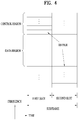
- FIG. 9 illustrates an exemplary PRACH preamble that may be used in embodiments of the present invention.
- the PRACH preamble is divided into a Cyclic Prefix (CP) of length T CP and a sequence of length T SEQ .
- Parameters for the CP and the sequence are determined according to a frame structure and a random access configuration.
- Table 2 lists CPs (T CP ) and sequences (T SEQ ) for different preamble formats.
- Transmission of a random access preamble is confined to specific time and frequency resources in frame structure type 2 and a specific subframe including a UpTPS. These resources are arranged in an ascending order of subframe numbers in a radio frame, starting from a PRB having the lowest index corresponding to index 0 in a frequency area. PRACH resources within radio resources are indicated by PRACH resource indexes in the order illustrated in [Table 3] and [Table 4].
- preamble formats 0 to 3 are used. One random access resource per subframe at maximum is provided.
- [Table 3] lists subframes carrying allowed random access preambles for the preamble formats listed in [Table 2] and given configurations of frame structure type 1.
- a PRACH configuration index parameter, prach-Configuraitonlndex is indicated by a higher layer.
- N TA is a time offset between a UL radio frame and a DL radio frame.
- a UE that will perform handover may estimate the absolute value of a relative time offset of radio frame j between a serving cell and a target cell to be less than 153600 ⁇ T s .
- a PRACH frequency offset parameter, prach-FrequencyOffset n PRBoffset RA is expressed as a PRB number configured by a higher layer, satisfying 0 ⁇ n PRBoffset RA ⁇ N RB UL ⁇ 6.
- [Table 3] illustrates a mapping relationship among PRACH configuration indexes, preamble formats, system frame numbers, and subframe numbers.
- PRACH Configuration Index Preamble Format System frame number Subframe number
- PRACH Configuration Index Preamble Format System frame number Subframe number 0 0 Even 1 32 2 Even 1 1 0 Even 4 33 2 Even 4 2 0 Even 7 34 2 Even 7 3 0 Any 1 35 2 Any 1 4 0 Any 4 36 2 Any 4 5 0 Any 7 37 2 Any 7 6 0 Any 1, 6 38 2 Any 1, 6 7 0 Any 2 ,7 39 2 Any 2 ,7 8 0 Any 3, 8 40 2 Any 3, 8 9 0 Any 1, 4, 7 41 2 Any 1, 4, 7 10 0 Any 2, 5, 8 42 2 Any 2, 5, 8 11 0 Any 3, 6, 9 43 2 Any 3, 6, 9 12 0 Any 0, 2, 4, 6, 8 44 2 Any 0, 2, 4, 6, 8 13 0 Any 1, 3, 5, 7, 9 45 2 Any 1, 3, 5, 7, 9 14 0 Any 0, 1, 2, 3, 4, 5, 6, 7, 8, 9 46 N/A N/A N/
- a plurality of random access resources may exist in a UL frame according to a UL/DL configuration.
- Table 4 illustrates combinations of a preamble format, a PRACH density value D RA , and a version index r RA with respect to PRACH configuration indexes available in frame structure type 2.
- a PRACH configuration index parameter, Prach-ConfigurationIndex is given by a higher layer.
- a UE that will perform handover may estimate the absolute value of a relative time offset of radio frame j between a serving cell and a target cell to be less than 153600 ⁇ T s .
- PRACH configuration Index ( 4 ) UL/DL configuration (See Table 4.2-2) 0 1 2 3 4 5 6 0 (0,1,0,2) (0,1,0,1) (0,1,0,0) (0,1,0,2) (0,1,0,1) (0,1,0,0) (0,1,0,2) 1 (0,2,0,2) (0,2,0,1) (0,2,0,0) (0,2,0,2) (0,2,0,1) (0,2,0,0) (0,2,0,2) (0,2,0,1) (0,2,0,0) (0,2,0,2) 2 (0,1,1,2) (0,1,1,1) (0,1,1,0) (0,1,0,1) (0,1,0,0) N/A (0,1,1,1) 3 (0,0,0,2) (0,0,0,1) (0,0,0,0) (0,0,0,2) (0,0,0,1) (0,0,0,0,0) (0,0,0,2) 4 (0,0,1,2) (0,0,1,1) (0,0,1,1) (0,0,1,1)
- f RA indicates a frequency resource index in a considered time instance
- t RA 2 indicates the number of a UL subframe in which a preamble starts.
- UL subframe numbers start to be counted, starting from the first UL subframe between two contiguous DL-UL switch points as 0, and is excluded from preamble format 4.
- t RA 2 is expressed as (*).
- N TA indicates a time offset between a UL radio frame and a DL radio frame.
- N RB UL represents the number of UL RBs
- n PRB RA represents the first PRB allocated to a PRACH opportunity
- n PRB offset RA represents the first PRB available for a PRACH expressed as the number of PRBs configured by a higher layer, satisfying 0 ⁇ n PRBoffset RA ⁇ N RB UL ⁇ 6.
- n t indicates a system frame number and N SP indicates the number of DL-UL switch points in a radio frame.
- each radio access preamble has a bandwidth corresponding to 6 contiguous RBs.
- a random access preamble (i.e., an RACH preamble) is generated from a Zadoff Chu (ZC) sequence including a Zero Correlation Zone (ZCZ) generated from one or more Root Zadoff Chu (RZC) sequences.
- ZC Zadoff Chu
- ZCZ Zero Correlation Zone
- RZC Root Zadoff Chu
- a network configures a set of preamble sequences allowed for a UE.
- 64 preambles are available for each cell.
- a set of 64 preamble sequences including all possible cyclic shifts of an RZC sequence for a logical index RACH_ROOT_SEQUENCE are searched for in an ascending order of cyclic shifts in the cell.
- the root index RACH_ROOT_SEQUENCE is broadcast as part of system information. If the 64 preambles are not generated from a single RZC, additional preamble sequences may be acquired from root indexes successive to the corresponding root index until 64 sequences are all detected.
- the root indexes are cyclically repeated from logical index 0 to logical index 837.
- For the relationship between logical root sequence indexes and physical root sequence indexes u refer to [Table 9] and [Table 10] which will be described later.
- a u th RZC sequence is defined by [Equation 4].
- x u n e ⁇ j ⁇ un n + 1 N ZC , 0 ⁇ n ⁇ N ZC ⁇ 1
- N ZC of a ZC sequence is given in [Table 6].
- a random access preamble having a ZCZ of length N CS -1, X u,v (n) is defined from the u th RZC sequence using a cyclic shift as expressed in [Equation 5].
- x u , v n x u n + C v mod N ZC
- a cyclic shift C v used in [Equation 5] is given by [Equation 6].
- C v ⁇ vN CS V + 0,1 , ... , ⁇ N ZC / N CS ⁇ ⁇ 1 , N CS ⁇ 0 for unrestricted sets 0
- N CS is given in [Table 7] and [Table 8].
- a ZCZ configuration parameter is provided by a higher layer.
- a high-speed flag parameter provided by the higher layer indicates whether C v is selected from a restricted set or an unrestricted set.
- a parameter for a restricted set of cyclic shifts depends on d u . If N CS ⁇ d u ⁇ N ZC /3 , parameters for the restricted set are given as [Equation 8].
- Ncs is the length of a base ZC sequence.
- zeroCorrelationZoneConfig N CS value Unrestricted set Restricted set 0 0 15 1 13 18 2 15 22 3 18 26 4 22 32 5 26 38 6 32 46 7 38 55 8 46 68 9 59 82 10 76 100 11 93 128 12 119 158 13 167 202 14 279 237 15 419 -
- [Table 8] illustrates a mapping relationship between ZCZ configurations used for preamble format 4 and N CS values used for generation of RACH preambles.
- zeroCorrelationZoneConfig N CS value 0 2 1 4 2 6 3 8 4 10 5 12 6 15 7 N/A 8 N/A 9 N/A 10 N/A 11 N/A 12 N/A 13 N/A 14 N/A 15 N/A
- [Table 9] lists the orders of root ZC sequences for preamble formats 0 to 3.
- Logical root sequence number Physical root sequence number u (in increasing order of the corresponding logical sequence number) 0-23 129, 710, 140, 699, 120, 719, 210, 629, 168, 671, 84, 755, 105, 734, 93, 746, 70, 769, 60, 779 2, 837, 1, 838 24-29 56, 783, 112, 727, 148, 691 30-35 80, 759, 42, 797, 40, 799 36-41 35, 804, 73, 766, 146, 693 42-51 31, 808, 28, 811, 30, 809, 27, 812, 29, 810 52-63 24, 815, 48, 791, 68, 771, 74, 765, 178, 661, 136, 703 64-75 86, 753, 78, 761, 43, 796, 39, 800, 20, 819, 21, 818 76-89
- the PRACH parameters are indicated to a UE by higher-layer signaling (e.g., RRC signaling or MAC signaling).
- a PRACH-ConfigSIB Information Element (IE) and a PRACH-Config IE are used to explicitly indicate a PRACH configuration (i.e. PRACH parameters) in system information and mobility control information.
- the PRACH-Config IE is transmitted in System Information Block 2 (SIB2).
- SIB2 System Information Block 2
- Table 11 illustrates an example of the PRACH-Config IE.
- a highSpeedFlag parameter indicates whether cyclic shifts used for generation of RACH preambles are from a restricted set or an unrestricted set.
- a Prach-ConfiguIndex parameter specifies a PRACH configuration and a preamble format.
- a prach-FreqOffset parameter indicates a frequency position at which an RACH preamble will be transmitted.
- a rootSequenceIndex parameter indicates a root ZC sequence.
- a zeroCorrelationZoneConfig parameter indicates a cyclic shift value Ncs.
- FIG. 10 illustrates aggregation of two or more carriers at different geographical locations according to an embodiment of the present invention.
- a TA value applicable to a specific CC e.g., a PCC or PCell
- a PCC or PCell a TA value applicable to a specific CC
- a UE aggregates a plurality of different CCs in different frequency bands (i.e., much spaced from each other in the frequency domain) or having different propagation characteristics.
- repeaters such as a Remote Radio Header (RRH), a small cell, a pico cell, etc. may be deployed in a cell or at a cell boundary in order to extend coverage or remove a coverage hole.
- RRH Remote Radio Header
- CA is applicable even to a case in which a plurality of carriers at different geographical locations are aggregated.
- the UL transmission may adversely affect synchronization of UL signals transmitted in the plurality of CCs.
- the UE communicates with an eNB and an RRH using two aggregated CCs.
- the UE communicates with the eNB directly in one CC, CC1 and with the eNB via the RRH in the other CC, CC2.
- the propagation delay (or reception timing at the eNB) of a UL signal transmitted in CC1 by the UE may be different from the propagation delay of a UL signal transmitted in CC2 by the UE due to the location of the UE, frequency characteristics, etc. If a plurality of CCs have different propagation delays as in this case, the eNB and the UE should use a plurality of TAs.
- FIG. 11 illustrates transmission of UL data with different TAs in a CA environment in which two CCs are aggregated according to an embodiment of the present invention.
- FIG. 11(a) illustrates transmission of UL data (e.g., a PUSCH1 signal) in a PCell and FIG. 11(b) illustrates transmission of UL data (e.g., a PUSCH2 signal) in a SCell.
- a UE may apply different TAs, TA1 and TA2 in transmitting UL signals in the two CCs.
- a TA may be allocated independently on a CC group basis, a CC group having one or more CCs. This may be referred to as a TA Group (TAG). That is, one TA is applied commonly to all CCs of one TAG.
- a TA may be determined based on a PCC for a TAG having the PCC, or a TA adjusted through a random access procedure in the PCC may be applied to the whole TAG.
- a TA determined based on a specific SCC (e.g., a leader SCell) of the TAG may be applied to the whole TAG.
- a specific SCC e.g., a leader SCell
- the random access procedure performed in a SCC may be the contention-based or contention-free random access procedure described in FIG. 7 or 8 .
- legacy aggregated cells for CA belong to the same area.
- an attempt has been made to increase data throughput, extend cell coverage, and enhance user experience by deploying a plurality of small cells and/or RRHs. Accordingly, there is a need for aggregating a plurality of cells at different physical locations.
- Cells are classified into a PCell group including a PCell and a SCell group that does not include a PCell.
- the size of each cell group is 1 or larger. Because the SCell group does not include a PCell, a leader SCell (L-SCell) representing other SCells may function as a PCell.
- L-SCell leader SCell
- a UE and/or an eNB may perform SCell addition and SCell activation for actual data transmission.
- the UE and/or the eNB may perform SCell modification for modifying the configuration of a SCell, SCell deletion for releasing the configuration of the SCell, and/or SCell deactivation for discontinuing data transmission and reception in the SCell.
- the SCell addition/deletion/modification may be performed by RRC signaling and the SCell activation/deactivation may be performed by a MAC message.
- the TA value of the SCell may be different from that of a PCell. Accordingly, the UE may perform a random access procedure with the SCell to be added to acquire the TA value of the SCell.
- one or more PCells and one or more SCells are configured for an eNB (a macro eNB or a first eNB) and one or more SCells are configured for an RRH or a small cell (a second eNB).
- eNB a macro eNB or a first eNB
- SCells are configured for an RRH or a small cell (a second eNB).
- a PCell a PCell
- an eNB, an RRH, or a small cell operates in a SCell
- the eNB, the RRH, or the small cell will be referred to as a SCell.
- FIG. 12 illustrates one of methods for performing a random access procedure to add a geographically spaced SCell to CA according to an embodiment of the present invention.
- a UE is communicating in a PCell of an eNB (accordingly, the eNB will be referred to as a PCell, for the convenience of description).
- the eNB will be referred to as a PCell, for the convenience of description.
- SCell a geographically spaced SCell needs to be added.
- the UE performs cell measurement to acquire information about channel states of neighbor cells, for cell addition (S1210).
- the UE After the cell measurement, the UE transmits a measurement report message including information about a candidate SCell to be added to CA from among the neighbor cells to the PCell (S1220).
- the PCell may transmit a cell addition order message including information (e.g., cell IDs, a cell list, etc.) about one or more SCells to the UE (S1230).
- information e.g., cell IDs, a cell list, etc.
- the PCell may negotiate RACH information to be used for a random access procedure to be performed with the SCell to be added with the SCell through a backbone network.
- the RACH information includes information about an RACH resource area in which the RACH procedure will be performed and/or information about RACH parameters needed to generate an RACH preamble (refer to Clauses 3.3 to 3.5) (S1240).
- the PCell may perform step S1240 with the reported two or more candidate SCells.
- the PCell acquires RACH information about the SCell through the RACH information negotiation of step S1240 and transmits the RACH information to the UE.
- the PCell may transmit the RACH information to the UE by a PDCCH signal, RRC signaling, or MAC signaling (S1250).
- the UE may perform a contention-based initial RACH procedure with the SCell based on the RACH information received from the PCell.
- the RACH procedure described in FIG. 7 may be referred to (S1260).
- the UE may fast perform the initial RACH procedure with the SCell by acquiring the RACH information about the SCell in advance from the PCell without receiving a BCH signal and SIB2 information to acquire system information from the SCell.
- step S1240 may be performed before step S1230.
- the cell addition order message of step S1230 may further include the RACH information transmitted in step S1250.
- step S1250 may be skipped.
- FIG. 13 illustrates another of the methods for performing a random access procedure to add a geographically spaced SCell to CA according to an embodiment of the present invention.
- Steps S1310 to S1330 of FIG. 13 are identical to steps S1210 to S1230 of FIG. 12 and thus will not be described to avoid redundancy.
- a PCell negotiates RACH information and SCell information with a SCell (S1340).
- the PCell may acquire the SCell information as well as the RACH information about the SCell.
- the SCell information may include system information included in a SIB of the SCell and may further include DL synchronization information and/or SCell identification information about the SCell.
- the RACH information may include information about a dedicated RACH preamble to perform a contention-free RACH procedure, compared to FIG. 12 .
- the PCell acquires the RACH information and the SCell information about the SCell through the RACH information and SCell information negotiation performed in step S1340 and transmits the acquired information to the UE.
- the PCell may transmit the RACH information and the SCell information to the UE by a PDCCH signal, RRC signaling, or MAC signaling (S1350).
- the UE may perform the contention-free RACH procedure with the SCell based on the RACH information received from the PCell.
- the RACH procedure described in FIG. 8 may be referred to (S1360).
- the UE may fast perform the contention-free RACH procedure with the SCell by acquiring the RACH information and the SCell information about the SCell in advance from the PCell without receiving a BCH signal and SIB2 information to acquire a synchronization signal such as a PSS/SSS and system information from the SCell.
- step S1340 may be performed before step S1330.
- the cell addition order message of step S1330 may further include the RACH information and/or the SCell information transmitted in step S1350.
- step S1350 may be skipped.
- FIG. 14 illustrates one of RACH methods for maintaining UL synchronization with added cells after completion of a cell addition procedure according to an embodiment of the present invention.
- a PCell managed by a serving eNB and a geographically spaced SCell form a CA environment. It is assumed that the SCell has been added in the methods described with reference to FIGs. 12 and 13 (S1410).
- a UE needs to acquire UL synchronization with the SCell as well as the PCell, for communication.
- the PCell may command the UE to perform an RACH procedure for UL synchronization with the PCell and/or the SCell by a PDCCH order message (S1420).
- the eNB may indicate a cell with which the RACH procedure will be performed.
- the cell with which the RACH procedure will be performed may be indicated by a reserved bit of the PDCCH order message or one or more of predetermined fields of the PDCCH order message.
- the UE may perform the RACH procedure with the PCell by detecting a PDCCH signal masked with an RA-RNTI in a Common Search Space (CSS) (S1430a).
- CSS Common Search Space
- the UE may perform the RACH procedure with the SCell by detecting a PDCCH signal masked with an RA-RNTI in a CSS of the SCell or a UE-specific Search Space (USS) (S1430b).
- a PDCCH signal masked with an RA-RNTI in a CSS of the SCell or a UE-specific Search Space (USS) (S1430b).
- USS UE-specific Search Space
- both steps S1430a and S1430b may be performed.
- the UE maintains connections to the PCell and the SCell. Therefore, since the UE already knows C-RNTIs used for the PCell and the SCell, the UE may perform a contention-free RACH procedure using the C-RNTIs in steps S1430a and S1430b. If a new UE enters the CA network, the PCell may allocate different RACH resources from the existing RACH resources to the new UE, thereby preventing collision between the RACH procedure of the new UE and the UL synchronization acquisition procedure of the existing UE. Further, collision with the new UE may be avoided in the RACH procedure by allocating a temporary C-RNTI different from the existing RA-RNTI.
- the operation for indicating a cell with which the RACH procedure will be performed by a MAC message or RRC signaling in step S1420 of FIG. 14 is another embodiment of the present invention.
- a UE to which execution of the RACH procedure has been indicated by the PDCCH order in step S1420 of FIG. 14 may perform an initial RACH procedure with the PCell and/or the SCell.
- the UE may maintain the UL synchronization with the PCell and the SCell using the method described with reference to FIG. 14 .
- FIG. 15 illustrates another of the RACH methods for maintaining UL synchronization after a cell addition procedure is completed according to an embodiment of the present invention.
- FIG. 15 is about a method for indicating performing of an RACH procedure for maintaining UL synchronization not by a PCell but by a SCell. Accordingly, only the difference from FIG. 14 will be described below.
- the SCell Upon expiration of a predetermined time or upon generation of an event after the SCell is connected to a UE, there may be a need for maintaining UL synchronization.
- the SCell transmits a PDCCH order message to the UE so as to control the UE to perform an RACH procedure with the PCell and/or the SCell (S1520).
- the added SCell is an L-SCell or a case where a SCell group is added.
- An L-SCell of a SCell group may be a SCell having a lowest or highest cell index or a SCell with which a UE has performed an initial RACH procedure.
- a SCell set by the PCell may be an L-SCell.
- the SCell When a SCell is added and the added SCell is an L-SCell, it is necessary to indicate that the SCell is an L-SCell to the UE. This is because the L-SCell may initiate addition of a SCell of a SCell group. The UE may be indicated whether the SCell is an L-SCell in the following methods.
- FIG. 16 illustrates another of the methods for performing a random access procedure to add a geographically spaced L-SCell to CA according to an embodiment of the present invention.
- Steps S1610 to S1630 of FIG. 16 are identical to steps S1210 to S1239 of FIG. 12 and thus their description is pursuant to the description of FIG. 12 . Further, it is assumed that an L-SCell and the other SCells of a SCell group are connected via an ideal backhaul and belong to a TAG sharing the same TA value in the SCell group.
- a PCell may negotiate RACH information and/or L-SCell information for use in an RACH procedure of an added L-SCell with the L-SCell via the backbone network.
- the RACH information includes information about an RACH resource area for performing the RACH procedure and/or information about RACH parameters needed to generate an RACH preamble (refer to Clauses 3.3. to 3.5).
- the L-SCell information may include system information such as DL synchronization information and a SCell ID (S1640).
- the PCell acquires the RACH information about the L-SCell by the RACH information and/or SCell information negotiation of Step S1640 and transmits the acquired RACH information to the UE.
- the PCell may transmit the RACH information by a PDCCH signal, RRC signaling, or MAC signaling to the UE (S1650).
- the UE may perform a contention-based or contention-free RACH procedure using the RACH information received from the PCell.
- the RACH procedure may be performed in the same manner as the RACH procedure described with reference to FIG. 7 and/or FIG. 8 (S1660).
- the UE may fast perform the initial RACH procedure or the contention-free RACH procedure by acquiring the RACH information about the SCell in advance from the PCell, without receiving a BCH signal and SIB2 information for acquiring system information from the L-SCell.
- the PCell or the L-SCell may modify the L-SCell.
- the modification of the L-SCell should be shared among all of the PCell, the L-SCell, and the UE. For example, if the PCell modifies a SCell, the PCell may transmit the modification to the L-SCell and the UE via an X2 interface or by RRC signaling or a MAC message. If the L-SCell modifies the SCell, the L-SCell may transmit the modification to the PCell and the UE via an X2 interface or by RRC signaling or a MAC message.
- step S1640 may be performed before step S1630.
- the cell addition order message of step S1630 may further include the RACH information and/or the SCell information transmitted in step S1650 and thus step S1650 may be skipped.
- Apparatuses illustrated in FIG. 17 are means that can implement the methods described before with reference to FIGS. 1 to 16 .
- a UE may act as a transmitter on a UL and as a receiver on a DL.
- a BS may act as a receiver on a UL and as a transmitter on a DL.
- each of the UE and the BS may include a Transmission (Tx) module 1740 or 1750 and a Reception (Rx) module 1760 or 1770, for controlling transmission and reception of information, data, and/or messages, and an antenna 1700 or 1710 for transmitting and receiving information, data, and/or messages.
- Tx Transmission
- Rx Reception
- Each of the UE and the BS may further include a processor 1720 or 1730 for implementing the afore-described embodiments of the present invention and a memory 1780 or 1790 for temporarily or permanently storing operations of the processor 1720 or 1730.
- the embodiments of the present invention can be implemented using the components and functions of the afore-described UE and BS.
- the processors of the BS and the UE may perform an operation for adding a geographically spaced serving cell to CA and an operation for acquiring UL synchronization with geographically spaced serving cells when CA is implemented with the serving cells by combining the methods described before in Clauses 1 to 4.
- the Tx and Rx modules of the UE and the BS may perform a packet modulation/demodulation function for data transmission, a high-speed packet channel coding function, OFDMA packet scheduling, TDD packet scheduling, and/or channelization.
- Each of the UE and the BS of FIG. 17 may further include a low-power Radio Frequency (RF)/Intermediate Frequency (IF) module.
- RF Radio Frequency
- IF Intermediate Frequency
- the UE may be any of a Personal Digital Assistant (PDA), a cellular phone, a Personal Communication Service (PCS) phone, a Global System for Mobile (GSM) phone, a Wideband Code Division Multiple Access (WCDMA) phone, a Mobile Broadband System (MBS) phone, a hand-held PC, a laptop PC, a smart phone, a Multi Mode-Multi Band (MM-MB) terminal, etc.
- PDA Personal Digital Assistant
- PCS Personal Communication Service
- GSM Global System for Mobile
- WCDMA Wideband Code Division Multiple Access
- MBS Mobile Broadband System
- hand-held PC a laptop PC
- smart phone a Multi Mode-Multi Band (MM-MB) terminal, etc.
- MM-MB Multi Mode-Multi Band
- the smart phone is a terminal taking the advantages of both a mobile phone and a PDA. It incorporates the functions of a PDA, that is, scheduling and data communications such as fax transmission and reception and Internet connection into a mobile phone.
- the MB-MM terminal refers to a terminal which has a multi-modem chip built therein and which can operate in any of a mobile Internet system and other mobile communication systems (e.g. CDMA 2000, WCDMA, etc.).
- Embodiments of the present invention may be achieved by various means, for example, hardware, firmware, software, or a combination thereof.
- the methods according to exemplary embodiments of the present invention may be achieved by one or more Application Specific Integrated Circuits (ASICs), Digital Signal Processors (DSPs), Digital Signal Processing Devices (DSPDs), Programmable Logic Devices (PLDs), Field Programmable Gate Arrays (FPGAs), processors, controllers, microcontrollers, microprocessors, etc.
- ASICs Application Specific Integrated Circuits
- DSPs Digital Signal Processors
- DSPDs Digital Signal Processing Devices
- PLDs Programmable Logic Devices
- FPGAs Field Programmable Gate Arrays
- processors controllers, microcontrollers, microprocessors, etc.
- the methods according to the embodiments of the present invention may be implemented in the form of a module, a procedure, a function, etc. performing the above-described functions or operations.
- a software code may be stored in the memory 1780 or 1790 and executed by the processor 1720 or 1730.
- the memory is located at the interior or exterior of the processor and may transmit and receive data to and from the processor via various known means.
- Embodiments of the present invention are applicable to various wireless access systems including a 3GPP system, a 3GPP2 system, and/or an IEEE 802.xx system. In addition to these wireless access systems, the embodiments of the present invention are applicable to all technical fields in which the wireless access systems find their applications.
Landscapes
- Engineering & Computer Science (AREA)
- Signal Processing (AREA)
- Computer Networks & Wireless Communication (AREA)
- Databases & Information Systems (AREA)
- Quality & Reliability (AREA)
- Mobile Radio Communication Systems (AREA)
Claims (10)
- Verfahren zur Unterstützung der Erfassung der Uplink-Synchronisation in einem drahtlosen Zugangssystem, das die Trägeraggregation (CA) unterstützt, wobei das Verfahren umfasst:Senden (S1340) von RACH-Parameterinformationen (RACH = Direktzugriffskanal), in Beziehung stehend mit einer ersten Direktzugriffsprozedur zur Erfassung der Uplink-Synchronisation mit einer Sekundärzelle (SCell), die der CA durch eine Vorrangzelle (PCell) hinzuzufügen ist;Erfassen (S1340) von RACH-Informationen einschließlich Ressourcenzuteilungsinformationen und der RACH-Parameterinformationen, wobei die Ressourcenzuteilungsinformationen einen Ressourcenbereich der SCell angeben, in dem die erste Direktzugriffsprozedur durchzuführen ist, und wobei die RACH-Parameterinformationen für die Generierung einer RACH-Präambel, die in der ersten Direktzugriffsprozedur zu verwenden ist, benötigt werden; undSenden (S1350) der RACH-Informationen über einen Physical Downlink Control Channel (PDCCH) an ein Benutzergerät (UE).
- Verfahren nach Anspruch 1, ferner umfassend:Senden (S1520) einer PDCCH-Anweisungsnachricht an das UE, die die Ausführung einer zweiten Direktzugriffsprozedur zur Erfassung der Uplink-Synchronisation anzeigt,wobei die PDCCH-Anweisungsnachricht Informationen einschließt, die eine Zelle angeben, mit der die zweite Direktzugriffsprozedur durchzuführen ist.
- Verfahren nach einem der Ansprüche 1 bis 2, wobei die SCell geografisch zu der PCell beabstandet ist.
- Verfahren nach einem der Ansprüche 1 bis 3, wobei die RACH-Informationen Systeminformationen einschließen, die in der SCell verwendet werden.
- Verfahren nach einem der Ansprüche 1 bis 4, wobei die SCell eine Führungs-SCell einer SCell-Gruppe, die eine oder mehrere SCells einschließt, ist.
- Vorrichtung zur Unterstützung der Erfassung der Uplink-Synchronisation in einem drahtlosen Zugangssystem, das die Trägeraggregation (CA) unterstützt, wobei die Vorrichtung umfasst:einen Sender (1750);einen Empfänger (1770); undeinen Prozessor (1730), der so konfiguriert ist, dass er die Erfassung der Uplink-Synchronisation unterstützt,wobei der Prozessor so konfiguriert ist, dass er:RACH-Parameterinformationen sendet (RACH = Direktzugriffskanal), in Beziehung stehend mit einer ersten Direktzugriffsprozedur zur Erfassung der Uplink-Synchronisation mit einer Sekundärzelle (SCell), die der CA durch eine Vorrangzelle der Vorrichtung hinzuzufügen ist, durch Steuern des Senders und des Empfängers,RACH-Informationen einschließlich Ressourcenzuteilungsinformationen und der RACH-Parameterinformationen erfasst, wobei die Ressourcenzuteilungsinformationen einen Ressourcenbereich der SCell angeben, in dem die erste Direktzugriffsprozedur durchzuführen ist, und wobei die RACH-Parameterinformationen für die Generierung einer RACH-Präambel, die in der ersten Direktzugriffsprozedur zu verwenden ist, benötigt werden, unddie RACH-Informationen über einen Physical Downlink Control Channel (PDCCH) an ein Benutzergerät (UE) durch Steuern des Senders sendet.
- Vorrichtung nach Anspruch 6, wobei der Prozessor ferner so konfiguriert ist, dass er eine PDCCH-Anweisungsnachricht, die die Ausführung einer zweiten Direktzugriffsprozedur zur Erfassung der Uplink-Synchronisation anzeigt, durch Steuern des Senders an das UE sendet, und
wobei die PDCCH-Anweisungsnachricht Informationen einschließt, die eine Zelle angeben, mit der die zweite Direktzugriffsprozedur durchzuführen ist. - Vorrichtung nach einem der Ansprüche 6 bis 7, wobei die SCell geografisch zu der PCell beabstandet ist.
- Vorrichtung nach einem der Ansprüche 6 bis 8, wobei die RACH-Informationen Systeminformationen einschließen, die in der SCell verwendet werden.
- Vorrichtung nach einem der Ansprüche 6 bis 9, wobei die SCell eine Führungs-SCell einer SCell-Gruppe, die eine oder mehrere SCells einschließt, ist.
Applications Claiming Priority (2)
| Application Number | Priority Date | Filing Date | Title |
|---|---|---|---|
| US201261735992P | 2012-12-11 | 2012-12-11 | |
| PCT/KR2013/011343 WO2014092411A1 (ko) | 2012-12-11 | 2013-12-09 | 반송파 결합을 지원하는 무선접속 시스템에서 상향링크 동기 획득 방법 및 장치 |
Publications (3)
| Publication Number | Publication Date |
|---|---|
| EP2934049A1 EP2934049A1 (de) | 2015-10-21 |
| EP2934049A4 EP2934049A4 (de) | 2016-12-21 |
| EP2934049B1 true EP2934049B1 (de) | 2019-03-06 |
Family
ID=50934634
Family Applications (1)
| Application Number | Title | Priority Date | Filing Date |
|---|---|---|---|
| EP13863524.8A Active EP2934049B1 (de) | 2012-12-11 | 2013-12-09 | Verfahren und vorrichtung zur erfassung einer uplink-synchronisation in einem drahtlosen zugangssystem mit trägeraggregationsunterstützung |
Country Status (4)
| Country | Link |
|---|---|
| US (1) | US10080216B2 (de) |
| EP (1) | EP2934049B1 (de) |
| CN (1) | CN104838704B (de) |
| WO (1) | WO2014092411A1 (de) |
Families Citing this family (19)
| Publication number | Priority date | Publication date | Assignee | Title |
|---|---|---|---|---|
| CN103249169B (zh) * | 2012-02-03 | 2016-08-31 | 华为技术有限公司 | 传输随机接入应答消息的方法、基站和用户设备 |
| BR112015032701A2 (pt) * | 2013-07-01 | 2017-07-25 | Huawei Tech Co Ltd | método de sincronização com base em interface aérea, estação de base, aparelho de controle e sistema de comunicações sem fio |
| JP6425891B2 (ja) * | 2014-01-14 | 2018-11-21 | 株式会社Nttドコモ | ユーザ端末および無線通信方法 |
| EP3404860B1 (de) * | 2014-06-03 | 2023-08-02 | Huawei Technologies Co., Ltd. | Verfahren zur erzeugung einer zufälligen zc-kanalfolge und vorrichtung |
| CN107302798A (zh) * | 2016-04-15 | 2017-10-27 | 中兴通讯股份有限公司 | 随机接入方法、装置及系统、基站和用户设备ue |
| US11452136B2 (en) * | 2016-08-12 | 2022-09-20 | Futurewei Technologies, Inc | System and method for network access |
| CN108541074B (zh) | 2017-03-06 | 2023-10-31 | 中兴通讯股份有限公司 | 随机接入发送方法、接收方法及装置、发射端及接收端 |
| CN108811162B (zh) * | 2017-05-04 | 2020-06-19 | 维沃移动通信有限公司 | 一种系统信息传输方法、终端及基站 |
| US10820225B2 (en) * | 2017-05-05 | 2020-10-27 | Motorola Mobility Llc | Method and apparatus for transmitting a RACH preamble on a wireless network |
| US10932296B2 (en) | 2017-08-07 | 2021-02-23 | Htc Corporation | Device and method of handling physical random access channel resources on a secondary cell in carrier aggregation |
| CN109451592B (zh) * | 2017-09-08 | 2020-06-16 | 华为技术有限公司 | 信息传输的方法和装置 |
| EP4301072B1 (de) * | 2017-11-15 | 2025-10-29 | Nokia Technologies Oy | Direktzugriff mit bandbreitenteilschalter |
| EP3738374B1 (de) * | 2018-01-11 | 2023-01-04 | Fg Innovation Company Limited | Uplink-trägerkonfiguration und auswahl mit zusätzlichem uplink |
| CN110300423B (zh) * | 2018-03-22 | 2022-12-20 | 华硕电脑股份有限公司 | 无线通信系统中用于波束故障处置的方法和设备 |
| US11284434B2 (en) * | 2019-05-14 | 2022-03-22 | Qualcomm Incorporated | Inter-cell coordination of random access channel transmission |
| EP3991461A4 (de) | 2019-06-28 | 2023-01-25 | Nokia Technologies Oy | Frühe datenübertragung für duale konnektivität oder trägeraggregation |
| KR102418147B1 (ko) * | 2019-10-03 | 2022-07-08 | 엘지전자 주식회사 | 무선 통신 시스템에서 신호를 송수신하는 방법 및 장치 |
| WO2022065887A1 (ko) | 2020-09-28 | 2022-03-31 | 삼성전자 주식회사 | 전자 장치의 수신 빔 선택 방법 및 전자 장치 |
| WO2024100560A1 (en) * | 2022-11-07 | 2024-05-16 | Telefonaktiebolaget Lm Ericsson (Publ) | Physical downlink control channel (pdcch) order enhancement for wireless communication |
Family Cites Families (20)
| Publication number | Priority date | Publication date | Assignee | Title |
|---|---|---|---|---|
| KR101089838B1 (ko) * | 2008-08-13 | 2011-12-05 | 한국전자통신연구원 | 캐리어 집성을 사용하는 통신 시스템 및 상기 통신 시스템에 속하는 기지국 및 단말 |
| KR101607846B1 (ko) * | 2009-01-06 | 2016-04-01 | 삼성전자주식회사 | 무선통신시스템에서 동기 채널 생성 장치 및 방법 |
| KR101559801B1 (ko) * | 2009-04-21 | 2015-10-13 | 엘지전자 주식회사 | 반송파집합 방식을 이용한 통신 시스템에서 rrc 연결 또는 재연결을 수행하는 방법 |
| KR20110108226A (ko) * | 2010-03-26 | 2011-10-05 | 삼성전자주식회사 | 이동 통신 시스템에서 캐리어를 활성화하는 방법 및 장치 |
| US20120082107A1 (en) | 2010-10-05 | 2012-04-05 | Ou Meng-Hui | Method and apparatus for implicit scell deactivation in a wireless communication system |
| KR102073027B1 (ko) * | 2011-04-05 | 2020-02-04 | 삼성전자 주식회사 | 반송파 집적 기술을 사용하는 무선통신시스템에서 복수 개의 타임 정렬 타이머 운용 방법 및 장치 |
| KR102072558B1 (ko) * | 2011-04-05 | 2020-02-03 | 삼성전자 주식회사 | 반송파 집적 시스템에서 반송파 활성화 방법 및 장치 |
| US9408168B2 (en) * | 2011-04-28 | 2016-08-02 | Lg Electronics Inc. | Method and apparatus for transmitting synchronization signal in carrier aggregation system |
| US20120300714A1 (en) | 2011-05-06 | 2012-11-29 | Samsung Electronics Co., Ltd. | Methods and apparatus for random access procedures with carrier aggregation for lte-advanced systems |
| US9681405B2 (en) * | 2011-05-10 | 2017-06-13 | Samsung Electronics Co., Ltd. | Method and apparatus for applying a time alignment timer in a wireless communication system using a carrier aggregation technique |
| KR20120136867A (ko) * | 2011-06-10 | 2012-12-20 | 주식회사 팬택 | 다중 요소 반송파 시스템에서 상향링크 동기의 수행장치 및 방법 |
| CN102244927B (zh) | 2011-07-22 | 2015-01-28 | 新邮通信设备有限公司 | 多小区长期演进系统中建立上行同步的方法、设备和终端 |
| CN102271418B (zh) | 2011-07-28 | 2016-04-20 | 电信科学技术研究院 | 一种随机接入的方法及装置 |
| US9191166B2 (en) * | 2011-11-04 | 2015-11-17 | Samsung Electronics Co., Ltd. | Apparatus and method for defining timing reference for secondary cells in a secondary timing advance group |
| CN104126281B (zh) * | 2012-01-11 | 2018-06-15 | 诺基亚通信公司 | 用于站间载波聚合的辅小区准备的方法和装置 |
| CN102548015A (zh) | 2012-01-13 | 2012-07-04 | 电信科学技术研究院 | 一种随机接入及其控制方法、装置和系统 |
| US9516627B2 (en) * | 2012-02-10 | 2016-12-06 | Nokia Solutions And Networks Oy | Inter-site carrier aggregation |
| ES2636014T3 (es) * | 2012-03-23 | 2017-10-05 | Mediatek Inc. | Métodos para configuración de agregación de portador multipunto y reenvió de datos |
| US20140038605A1 (en) * | 2012-07-31 | 2014-02-06 | Firouz Behnamfar | Devices and methods for cellular communication |
| US20140038616A1 (en) * | 2012-07-31 | 2014-02-06 | Richard Charles Burbidge | Devices and methods for cellular communication |
-
2013
- 2013-12-09 CN CN201380064910.XA patent/CN104838704B/zh active Active
- 2013-12-09 EP EP13863524.8A patent/EP2934049B1/de active Active
- 2013-12-09 WO PCT/KR2013/011343 patent/WO2014092411A1/ko not_active Ceased
- 2013-12-09 US US14/651,088 patent/US10080216B2/en active Active
Non-Patent Citations (1)
| Title |
|---|
| None * |
Also Published As
| Publication number | Publication date |
|---|---|
| WO2014092411A1 (ko) | 2014-06-19 |
| EP2934049A4 (de) | 2016-12-21 |
| CN104838704A (zh) | 2015-08-12 |
| US20150327218A1 (en) | 2015-11-12 |
| US10080216B2 (en) | 2018-09-18 |
| CN104838704B (zh) | 2019-02-22 |
| EP2934049A1 (de) | 2015-10-21 |
Similar Documents
| Publication | Publication Date | Title |
|---|---|---|
| EP2934049B1 (de) | Verfahren und vorrichtung zur erfassung einer uplink-synchronisation in einem drahtlosen zugangssystem mit trägeraggregationsunterstützung | |
| EP2950471B1 (de) | Verfahren zum hinzufügen einer sekundärzelle in einem drahtlosen zugangssystem mit unterstützung von trägeraggregation und vorrichtung zur unterstützung davon | |
| US9814076B2 (en) | Method for performing high-speed initial access process in wireless access system supporting ultrahigh frequency band, and device supporting same | |
| EP3226630B1 (de) | Vorrichtung und verfahren zur ausführung einer direkten d2d-kommunikation in einem drahtloskommunikationssystem mit unterstützung eines unlizenzierten bandes | |
| EP2768170B1 (de) | Verfahren und vorrichtung zur zuweisung von übertragungszeiten an mehrere zeitfortschrittsgruppen in einem drahtlosen kommunikationssystem für trägeraggregationsunterstützung | |
| EP2978151A2 (de) | Rundfunkkanalverfahren, verfahren zum senden und empfangen eines rundfunkkanalsignals und vorrichtung zur unterstützung davon | |
| EP3062542B1 (de) | Verfahren zur übertragung von broadcastkanälen in einem drahtlosen zugangssystem zur unterstützung einer maschinenkommunikation und vorrichtung damit | |
| US9736659B2 (en) | Method for allocating broadcast channel, method for transmitting and receiving broadcast channel signal, and device for supporting same | |
| US10225811B2 (en) | Method for obtaining synchronization between devices in wireless access system supporting device-to-device communication, and device supporting same | |
| US11412552B2 (en) | Method and apparatus for transmitting a random access preamble in a narrow band IoT system supporting time division duplexing | |
| EP3094023A1 (de) | Verfahren und vorrichtung zur herstellung einer rahmenstruktur in drahtloszugangssystem mit unterstützung von fdr-übertragung | |
| CN104756421A (zh) | 用于收发tdd的方法和用户设备 | |
| EP3664563B1 (de) | Verfahren zur übertragung einer direktzugriffspräambel in einem schmalband-iot-system mit unterstützung von zeitduplexbetrieb und vorrichtung dafür |
Legal Events
| Date | Code | Title | Description |
|---|---|---|---|
| PUAI | Public reference made under article 153(3) epc to a published international application that has entered the european phase |
Free format text: ORIGINAL CODE: 0009012 |
|
| 17P | Request for examination filed |
Effective date: 20150706 |
|
| AK | Designated contracting states |
Kind code of ref document: A1 Designated state(s): AL AT BE BG CH CY CZ DE DK EE ES FI FR GB GR HR HU IE IS IT LI LT LU LV MC MK MT NL NO PL PT RO RS SE SI SK SM TR |
|
| AX | Request for extension of the european patent |
Extension state: BA ME |
|
| DAX | Request for extension of the european patent (deleted) | ||
| RIC1 | Information provided on ipc code assigned before grant |
Ipc: H04W 56/00 20090101AFI20160705BHEP Ipc: H04W 74/08 20090101ALI20160705BHEP |
|
| A4 | Supplementary search report drawn up and despatched |
Effective date: 20161121 |
|
| RIC1 | Information provided on ipc code assigned before grant |
Ipc: H04W 74/08 20090101ALI20161115BHEP Ipc: H04W 56/00 20090101AFI20161115BHEP |
|
| GRAP | Despatch of communication of intention to grant a patent |
Free format text: ORIGINAL CODE: EPIDOSNIGR1 |
|
| STAA | Information on the status of an ep patent application or granted ep patent |
Free format text: STATUS: GRANT OF PATENT IS INTENDED |
|
| INTG | Intention to grant announced |
Effective date: 20180423 |
|
| GRAS | Grant fee paid |
Free format text: ORIGINAL CODE: EPIDOSNIGR3 |
|
| GRAJ | Information related to disapproval of communication of intention to grant by the applicant or resumption of examination proceedings by the epo deleted |
Free format text: ORIGINAL CODE: EPIDOSDIGR1 |
|
| GRAL | Information related to payment of fee for publishing/printing deleted |
Free format text: ORIGINAL CODE: EPIDOSDIGR3 |
|
| STAA | Information on the status of an ep patent application or granted ep patent |
Free format text: STATUS: REQUEST FOR EXAMINATION WAS MADE |
|
| GRAP | Despatch of communication of intention to grant a patent |
Free format text: ORIGINAL CODE: EPIDOSNIGR1 |
|
| STAA | Information on the status of an ep patent application or granted ep patent |
Free format text: STATUS: GRANT OF PATENT IS INTENDED |
|
| INTC | Intention to grant announced (deleted) | ||
| INTG | Intention to grant announced |
Effective date: 20180920 |
|
| GRAA | (expected) grant |
Free format text: ORIGINAL CODE: 0009210 |
|
| STAA | Information on the status of an ep patent application or granted ep patent |
Free format text: STATUS: THE PATENT HAS BEEN GRANTED |
|
| AK | Designated contracting states |
Kind code of ref document: B1 Designated state(s): AL AT BE BG CH CY CZ DE DK EE ES FI FR GB GR HR HU IE IS IT LI LT LU LV MC MK MT NL NO PL PT RO RS SE SI SK SM TR |
|
| REG | Reference to a national code |
Ref country code: GB Ref legal event code: FG4D |
|
| REG | Reference to a national code |
Ref country code: CH Ref legal event code: EP Ref country code: AT Ref legal event code: REF Ref document number: 1106323 Country of ref document: AT Kind code of ref document: T Effective date: 20190315 |
|
| REG | Reference to a national code |
Ref country code: DE Ref legal event code: R096 Ref document number: 602013052041 Country of ref document: DE |
|
| REG | Reference to a national code |
Ref country code: IE Ref legal event code: FG4D |
|
| REG | Reference to a national code |
Ref country code: NL Ref legal event code: MP Effective date: 20190306 |
|
| REG | Reference to a national code |
Ref country code: LT Ref legal event code: MG4D |
|
| PG25 | Lapsed in a contracting state [announced via postgrant information from national office to epo] |
Ref country code: LT Free format text: LAPSE BECAUSE OF FAILURE TO SUBMIT A TRANSLATION OF THE DESCRIPTION OR TO PAY THE FEE WITHIN THE PRESCRIBED TIME-LIMIT Effective date: 20190306 Ref country code: FI Free format text: LAPSE BECAUSE OF FAILURE TO SUBMIT A TRANSLATION OF THE DESCRIPTION OR TO PAY THE FEE WITHIN THE PRESCRIBED TIME-LIMIT Effective date: 20190306 Ref country code: NO Free format text: LAPSE BECAUSE OF FAILURE TO SUBMIT A TRANSLATION OF THE DESCRIPTION OR TO PAY THE FEE WITHIN THE PRESCRIBED TIME-LIMIT Effective date: 20190606 Ref country code: SE Free format text: LAPSE BECAUSE OF FAILURE TO SUBMIT A TRANSLATION OF THE DESCRIPTION OR TO PAY THE FEE WITHIN THE PRESCRIBED TIME-LIMIT Effective date: 20190306 |
|
| PG25 | Lapsed in a contracting state [announced via postgrant information from national office to epo] |
Ref country code: BG Free format text: LAPSE BECAUSE OF FAILURE TO SUBMIT A TRANSLATION OF THE DESCRIPTION OR TO PAY THE FEE WITHIN THE PRESCRIBED TIME-LIMIT Effective date: 20190606 Ref country code: GR Free format text: LAPSE BECAUSE OF FAILURE TO SUBMIT A TRANSLATION OF THE DESCRIPTION OR TO PAY THE FEE WITHIN THE PRESCRIBED TIME-LIMIT Effective date: 20190607 Ref country code: RS Free format text: LAPSE BECAUSE OF FAILURE TO SUBMIT A TRANSLATION OF THE DESCRIPTION OR TO PAY THE FEE WITHIN THE PRESCRIBED TIME-LIMIT Effective date: 20190306 Ref country code: LV Free format text: LAPSE BECAUSE OF FAILURE TO SUBMIT A TRANSLATION OF THE DESCRIPTION OR TO PAY THE FEE WITHIN THE PRESCRIBED TIME-LIMIT Effective date: 20190306 Ref country code: HR Free format text: LAPSE BECAUSE OF FAILURE TO SUBMIT A TRANSLATION OF THE DESCRIPTION OR TO PAY THE FEE WITHIN THE PRESCRIBED TIME-LIMIT Effective date: 20190306 Ref country code: NL Free format text: LAPSE BECAUSE OF FAILURE TO SUBMIT A TRANSLATION OF THE DESCRIPTION OR TO PAY THE FEE WITHIN THE PRESCRIBED TIME-LIMIT Effective date: 20190306 |
|
| REG | Reference to a national code |
Ref country code: AT Ref legal event code: MK05 Ref document number: 1106323 Country of ref document: AT Kind code of ref document: T Effective date: 20190306 |
|
| PG25 | Lapsed in a contracting state [announced via postgrant information from national office to epo] |
Ref country code: CZ Free format text: LAPSE BECAUSE OF FAILURE TO SUBMIT A TRANSLATION OF THE DESCRIPTION OR TO PAY THE FEE WITHIN THE PRESCRIBED TIME-LIMIT Effective date: 20190306 Ref country code: RO Free format text: LAPSE BECAUSE OF FAILURE TO SUBMIT A TRANSLATION OF THE DESCRIPTION OR TO PAY THE FEE WITHIN THE PRESCRIBED TIME-LIMIT Effective date: 20190306 Ref country code: PT Free format text: LAPSE BECAUSE OF FAILURE TO SUBMIT A TRANSLATION OF THE DESCRIPTION OR TO PAY THE FEE WITHIN THE PRESCRIBED TIME-LIMIT Effective date: 20190706 Ref country code: AL Free format text: LAPSE BECAUSE OF FAILURE TO SUBMIT A TRANSLATION OF THE DESCRIPTION OR TO PAY THE FEE WITHIN THE PRESCRIBED TIME-LIMIT Effective date: 20190306 Ref country code: ES Free format text: LAPSE BECAUSE OF FAILURE TO SUBMIT A TRANSLATION OF THE DESCRIPTION OR TO PAY THE FEE WITHIN THE PRESCRIBED TIME-LIMIT Effective date: 20190306 Ref country code: SK Free format text: LAPSE BECAUSE OF FAILURE TO SUBMIT A TRANSLATION OF THE DESCRIPTION OR TO PAY THE FEE WITHIN THE PRESCRIBED TIME-LIMIT Effective date: 20190306 Ref country code: IT Free format text: LAPSE BECAUSE OF FAILURE TO SUBMIT A TRANSLATION OF THE DESCRIPTION OR TO PAY THE FEE WITHIN THE PRESCRIBED TIME-LIMIT Effective date: 20190306 Ref country code: EE Free format text: LAPSE BECAUSE OF FAILURE TO SUBMIT A TRANSLATION OF THE DESCRIPTION OR TO PAY THE FEE WITHIN THE PRESCRIBED TIME-LIMIT Effective date: 20190306 |
|
| PG25 | Lapsed in a contracting state [announced via postgrant information from national office to epo] |
Ref country code: SM Free format text: LAPSE BECAUSE OF FAILURE TO SUBMIT A TRANSLATION OF THE DESCRIPTION OR TO PAY THE FEE WITHIN THE PRESCRIBED TIME-LIMIT Effective date: 20190306 Ref country code: PL Free format text: LAPSE BECAUSE OF FAILURE TO SUBMIT A TRANSLATION OF THE DESCRIPTION OR TO PAY THE FEE WITHIN THE PRESCRIBED TIME-LIMIT Effective date: 20190306 |
|
| REG | Reference to a national code |
Ref country code: DE Ref legal event code: R097 Ref document number: 602013052041 Country of ref document: DE |
|
| PG25 | Lapsed in a contracting state [announced via postgrant information from national office to epo] |
Ref country code: IS Free format text: LAPSE BECAUSE OF FAILURE TO SUBMIT A TRANSLATION OF THE DESCRIPTION OR TO PAY THE FEE WITHIN THE PRESCRIBED TIME-LIMIT Effective date: 20190706 Ref country code: AT Free format text: LAPSE BECAUSE OF FAILURE TO SUBMIT A TRANSLATION OF THE DESCRIPTION OR TO PAY THE FEE WITHIN THE PRESCRIBED TIME-LIMIT Effective date: 20190306 |
|
| PLBE | No opposition filed within time limit |
Free format text: ORIGINAL CODE: 0009261 |
|
| STAA | Information on the status of an ep patent application or granted ep patent |
Free format text: STATUS: NO OPPOSITION FILED WITHIN TIME LIMIT |
|
| PG25 | Lapsed in a contracting state [announced via postgrant information from national office to epo] |
Ref country code: DK Free format text: LAPSE BECAUSE OF FAILURE TO SUBMIT A TRANSLATION OF THE DESCRIPTION OR TO PAY THE FEE WITHIN THE PRESCRIBED TIME-LIMIT Effective date: 20190306 |
|
| 26N | No opposition filed |
Effective date: 20191209 |
|
| PG25 | Lapsed in a contracting state [announced via postgrant information from national office to epo] |
Ref country code: SI Free format text: LAPSE BECAUSE OF FAILURE TO SUBMIT A TRANSLATION OF THE DESCRIPTION OR TO PAY THE FEE WITHIN THE PRESCRIBED TIME-LIMIT Effective date: 20190306 |
|
| PG25 | Lapsed in a contracting state [announced via postgrant information from national office to epo] |
Ref country code: TR Free format text: LAPSE BECAUSE OF FAILURE TO SUBMIT A TRANSLATION OF THE DESCRIPTION OR TO PAY THE FEE WITHIN THE PRESCRIBED TIME-LIMIT Effective date: 20190306 |
|
| REG | Reference to a national code |
Ref country code: CH Ref legal event code: PL |
|
| REG | Reference to a national code |
Ref country code: BE Ref legal event code: MM Effective date: 20191231 |
|
| PG25 | Lapsed in a contracting state [announced via postgrant information from national office to epo] |
Ref country code: MC Free format text: LAPSE BECAUSE OF FAILURE TO SUBMIT A TRANSLATION OF THE DESCRIPTION OR TO PAY THE FEE WITHIN THE PRESCRIBED TIME-LIMIT Effective date: 20190306 |
|
| PG25 | Lapsed in a contracting state [announced via postgrant information from national office to epo] |
Ref country code: IE Free format text: LAPSE BECAUSE OF NON-PAYMENT OF DUE FEES Effective date: 20191209 Ref country code: LU Free format text: LAPSE BECAUSE OF NON-PAYMENT OF DUE FEES Effective date: 20191209 |
|
| PG25 | Lapsed in a contracting state [announced via postgrant information from national office to epo] |
Ref country code: BE Free format text: LAPSE BECAUSE OF NON-PAYMENT OF DUE FEES Effective date: 20191231 Ref country code: CH Free format text: LAPSE BECAUSE OF NON-PAYMENT OF DUE FEES Effective date: 20191231 Ref country code: LI Free format text: LAPSE BECAUSE OF NON-PAYMENT OF DUE FEES Effective date: 20191231 |
|
| PG25 | Lapsed in a contracting state [announced via postgrant information from national office to epo] |
Ref country code: CY Free format text: LAPSE BECAUSE OF FAILURE TO SUBMIT A TRANSLATION OF THE DESCRIPTION OR TO PAY THE FEE WITHIN THE PRESCRIBED TIME-LIMIT Effective date: 20190306 |
|
| PG25 | Lapsed in a contracting state [announced via postgrant information from national office to epo] |
Ref country code: HU Free format text: LAPSE BECAUSE OF FAILURE TO SUBMIT A TRANSLATION OF THE DESCRIPTION OR TO PAY THE FEE WITHIN THE PRESCRIBED TIME-LIMIT; INVALID AB INITIO Effective date: 20131209 Ref country code: MT Free format text: LAPSE BECAUSE OF FAILURE TO SUBMIT A TRANSLATION OF THE DESCRIPTION OR TO PAY THE FEE WITHIN THE PRESCRIBED TIME-LIMIT Effective date: 20190306 |
|
| PG25 | Lapsed in a contracting state [announced via postgrant information from national office to epo] |
Ref country code: MK Free format text: LAPSE BECAUSE OF FAILURE TO SUBMIT A TRANSLATION OF THE DESCRIPTION OR TO PAY THE FEE WITHIN THE PRESCRIBED TIME-LIMIT Effective date: 20190306 |
|
| P01 | Opt-out of the competence of the unified patent court (upc) registered |
Effective date: 20230524 |
|
| PGFP | Annual fee paid to national office [announced via postgrant information from national office to epo] |
Ref country code: DE Payment date: 20251105 Year of fee payment: 13 |
|
| PGFP | Annual fee paid to national office [announced via postgrant information from national office to epo] |
Ref country code: GB Payment date: 20251105 Year of fee payment: 13 |
|
| PGFP | Annual fee paid to national office [announced via postgrant information from national office to epo] |
Ref country code: FR Payment date: 20251111 Year of fee payment: 13 |