EP2934108B1 - Solarbetriebene insektenfalle - Google Patents
Solarbetriebene insektenfalle Download PDFInfo
- Publication number
- EP2934108B1 EP2934108B1 EP13864617.9A EP13864617A EP2934108B1 EP 2934108 B1 EP2934108 B1 EP 2934108B1 EP 13864617 A EP13864617 A EP 13864617A EP 2934108 B1 EP2934108 B1 EP 2934108B1
- Authority
- EP
- European Patent Office
- Prior art keywords
- trap
- insect trap
- damper
- housing
- insects
- Prior art date
- Legal status (The legal status is an assumption and is not a legal conclusion. Google has not performed a legal analysis and makes no representation as to the accuracy of the status listed.)
- Active
Links
Images




Classifications
-
- A—HUMAN NECESSITIES
- A01—AGRICULTURE; FORESTRY; ANIMAL HUSBANDRY; HUNTING; TRAPPING; FISHING
- A01M—CATCHING, TRAPPING OR SCARING OF ANIMALS; APPARATUS FOR THE DESTRUCTION OF NOXIOUS ANIMALS OR NOXIOUS PLANTS
- A01M1/00—Stationary means for catching or killing insects
- A01M1/08—Attracting and catching insects by using combined illumination or colours and suction effects
-
- A—HUMAN NECESSITIES
- A01—AGRICULTURE; FORESTRY; ANIMAL HUSBANDRY; HUNTING; TRAPPING; FISHING
- A01M—CATCHING, TRAPPING OR SCARING OF ANIMALS; APPARATUS FOR THE DESTRUCTION OF NOXIOUS ANIMALS OR NOXIOUS PLANTS
- A01M1/00—Stationary means for catching or killing insects
- A01M1/02—Stationary means for catching or killing insects with devices or substances, e.g. food, pheronones attracting the insects
- A01M1/023—Attracting insects by the simulation of a living being, i.e. emission of carbon dioxide, heat, sound waves or vibrations
-
- A—HUMAN NECESSITIES
- A01—AGRICULTURE; FORESTRY; ANIMAL HUSBANDRY; HUNTING; TRAPPING; FISHING
- A01M—CATCHING, TRAPPING OR SCARING OF ANIMALS; APPARATUS FOR THE DESTRUCTION OF NOXIOUS ANIMALS OR NOXIOUS PLANTS
- A01M1/00—Stationary means for catching or killing insects
- A01M1/02—Stationary means for catching or killing insects with devices or substances, e.g. food, pheronones attracting the insects
- A01M1/04—Attracting insects by using illumination or colours
-
- A—HUMAN NECESSITIES
- A01—AGRICULTURE; FORESTRY; ANIMAL HUSBANDRY; HUNTING; TRAPPING; FISHING
- A01M—CATCHING, TRAPPING OR SCARING OF ANIMALS; APPARATUS FOR THE DESTRUCTION OF NOXIOUS ANIMALS OR NOXIOUS PLANTS
- A01M1/00—Stationary means for catching or killing insects
- A01M1/06—Catching insects by using a suction effect
-
- A—HUMAN NECESSITIES
- A01—AGRICULTURE; FORESTRY; ANIMAL HUSBANDRY; HUNTING; TRAPPING; FISHING
- A01M—CATCHING, TRAPPING OR SCARING OF ANIMALS; APPARATUS FOR THE DESTRUCTION OF NOXIOUS ANIMALS OR NOXIOUS PLANTS
- A01M1/00—Stationary means for catching or killing insects
- A01M1/10—Catching insects by using Traps
- A01M1/106—Catching insects by using Traps for flying insects
-
- Y—GENERAL TAGGING OF NEW TECHNOLOGICAL DEVELOPMENTS; GENERAL TAGGING OF CROSS-SECTIONAL TECHNOLOGIES SPANNING OVER SEVERAL SECTIONS OF THE IPC; TECHNICAL SUBJECTS COVERED BY FORMER USPC CROSS-REFERENCE ART COLLECTIONS [XRACs] AND DIGESTS
- Y02—TECHNOLOGIES OR APPLICATIONS FOR MITIGATION OR ADAPTATION AGAINST CLIMATE CHANGE
- Y02E—REDUCTION OF GREENHOUSE GAS [GHG] EMISSIONS, RELATED TO ENERGY GENERATION, TRANSMISSION OR DISTRIBUTION
- Y02E10/00—Energy generation through renewable energy sources
- Y02E10/40—Solar thermal energy, e.g. solar towers
- Y02E10/46—Conversion of thermal power into mechanical power, e.g. Rankine, Stirling or solar thermal engines
Definitions
- This invention relates to a method and apparatus for trapping insects.
- an insect trap which utilizes an adjustable solar-panel roof that powers one or more of components within the trap, multiple attractants to attract insects to the trap, and an air-actuated two-piece damper that traps insects within the confines of the trap.
- Suction-type insect traps utilize a suction mechanism, such as a fan disposed in a chamber, to draw or blow air into the trap and capture any insects that are caught in the flow of air associated with operation of the fan. Captured insects must usually be retained or housed in a closed space to prevent the escape of insects from the trap. An attractant is also commonly used to lure insects to the air flow. Without such an attractant, only those insects that are exposed by happenstance to the air flow can commonly be captured.
- the prior art teaches the use of a variety of attractants, such as heat, water vapor, and carbon dioxide, to lure insects to the vicinity of a trap.
- attractants such as heat, water vapor, and carbon dioxide
- Such attractants simulate the elements that are found in the breath and sweat of warm-blooded mammals, the target of many biting and/or blood-sucking insects. Many insects are also attracted to light and will gather around light sources.
- the effectiveness of such insect traps depends largely on the combined effectiveness of the attractant, the suction or air flow mechanism, and the insect retaining capability of a cage associated with the trap.
- Carbon dioxide has been known to be used as an attractant, methods of carbon dioxide dispersion have been less commercially viable. Carbon dioxide gas used as an attractant is typically provided by pressurized tanks or by the sublimation of dry ice. While these methods supply carbon dioxide, they have not been commercially viable options since they are heavy and occupy a lot of space.
- An effective trap may involve a quiet yet powerful fan, but the trap must also be constructed so that insects are not able to escape once they are trapped within the confines of the trap. In particular, it is desirable for the insects to not escape when the fan is powered off and there is no longer any suction mechanism in effect within the trap.
- WO 2014/077932 A1 discloses a prior insect trap comprising:
- an insect trap according to claim 1. Additional aspects of the present invention are set out in the dependent claims.
- the four-way protection system involves: (1) a solar panel roof to supply power to the power consuming features of the trap; (2) one or more insect attractants; (3) an effective fan mechanism to overpower insects and direct them toward the trap; and (4) a secure retention mechanism that prevents escape of captured insects.
- an insect trap that does not use pesticides or emit otherwise harmful chemicals into the environment.
- an insect trap that utilizes a suction vacuum in conjunction with multiple non-chemical attractants. This method provides an environmentally friendly and odor-free method to eliminate unwanted insects without being unduly obtrusion to the enjoyment of people who may be nearby.
- an insect trap that ensnares the insects when the suction vacuum is turned off so that insects cannot escape. By doing so, the user is able to clean the trap or simply let the trap sit unpowered without insects escaping.
- an air-actuated damper which self-closes when the fan is off but provides adequate access to the insect cage during operation of the fan.
- the trap assembly be lightweight, easy to install, and convenient to use.
- a trap that is made of durable yet lightweight materials (e.g., plastic or metal) that can be easily carried by the user and then placed or hung in an indoor or outdoor environment.
- the trap is also preferably constructed and packaged so that it does not require assembly by the user.
- An effective trap provides insect protection for an area spanning anywhere from 1,000 square feet to at least 1 full acre of a yard or home. For best results, the trap is positioned away from competing light sources yet at the focal point of protection. Because placement of the trap at least partly determines insect collection effectiveness, ease in installing the trap at a preferred location is often desired. There is hereinafter disclosed how to provide an alternate means to supply power to an insect trap without relying upon the availability of a utility power source.
- an insect trap that is environmentally friendly and odor-free; includes a damper or insect passage assembly that prevents the undesired escape of captured insects; is lightweight, easy to install, and convenient to use; and is not reliant upon utility power for operation of the device.
- the disclosed insect trap assembly contemplates different embodiments depending on if it is intended for indoor or outdoor use, and encompasses different features depending on the specific needs of the user.
- the disclosed insect trap is for outdoor use and provides protection of the operating components of the trap assembly from the natural elements.
- the outdoor-use insect trap comprises three main housing elements: a roof, a body, and a retaining cage. It is contemplated that the trap may be further defined by other main housing elements.
- the disclosed outdoor-use insect trap has a rain roof which provides protection for the majority of the trap assembly from the natural elements, such as rain.
- the rain roof is attached to the body and may be removable or fixed.
- the attachment means for the rain roof may include vertical rods which suspend the roof above the body, or a securing mechanism that attaches the rain roof directly to the body.
- the rain roof is shaped to overlap the body and allow rain to run past the roof and fall past the body to prevent moisture from entering the interior of body.
- the rain roof may be constructed of a durable plastic or metal material.
- the rain roof or cover may have a transparent or translucent inlet or be constructed of a transparent or translucent material to allow light rays to emit beyond the trap assembly and attract insects.
- the roof of the disclosed insect trap includes solar cells that utilizes the sun's rays to power at least one power consuming component of the trap.
- the solar cells associated with the roof comprise a plurality of photovoltaic cells which convert solar energy into electricity through a photovoltaic effect. This electricity is used to power one or more of the power consuming components of the trap, e.g., a light source and/or a fan.
- the solar energy or excess solar energy may be stored in, e.g., batteries or thermal storage media such as collectors when the sun's rays are at maximum strength for use during overcast conditions or when solar rays are obscured.
- the power source may be switched from direct sun ray conversion to employing battery reserves when there are no sun rays, and vice versa when the sun is shining bright. This feature allows the insect trap to run continuously without reliance upon utility power.
- the solar cell roof may be constructed to allow one or more panels of the roof to be positioned at a desired angle to catch the maximum amount of sun rays.
- the panels may be frictionally hinged to allow the panel(s) to maintain a desired angled position.
- the panels may be moved manually, mechanically, or automatically, by remote control or other electrical switch. It is also contemplated that the hinge between the panels contains an edge guard to provide a smooth contour along the hinged joint.
- the insect trap can be used indoors, and thus, the housing construction may differ.
- the rain roof serves simply as a cover and does not necessarily protect the body from the natural elements or may be wholly removed. It may not overlap the body, but instead, may be constructed to be flush with the body to provide a smooth contour.
- the rain roof or cover serves as an attachment means for a light source, and the interior of the roof or cover may contain an electrical assembly to activate such light source. It is contemplated that the electrical assembly may be external to the insect trap or located in the trap body. It is envisioned that the electrical assembly can be connected to one or more of a power source, e.g., solar cell, A.C. or D.C. power supply, and/or battery or fuel cell to provide powered operation of the device during various conditions and/or uses.
- a power source e.g., solar cell, A.C. or D.C. power supply
- battery or fuel cell e.g., battery or fuel cell
- the rain roof or cover may provide an attachment means for a hook or handle so that the user can easily carry and transport the trap.
- the roof has a suspension ring to allow the insect trap to be hung.
- the roof has a handle to allow the user to easily pick up and carry the trap.
- the insect trap has a body which is generally cylindrical in shape and has several elements located within the interior of the body.
- one or more screens, a fan assembly, and a damper are located within the confines of the body.
- the body is constructed so that a vacuum air-flow is created by the fan assembly and the cylindrically shaped body. It is contemplated that other operational features may be located within the body.
- the roof or cover is attached to the body by a plurality of stiff vertical rods, and insects enter the trap through the space between the rods, cover and housing.
- the roof or cover is coupled to the body through a screw mechanism or other attachment means.
- the roof or cover is screwed or attached directly onto the body.
- the upper area of the body may also include vertical slots removed from the housing walls through which insects may enter the interior of the trap. Regardless of their shape and locations, the openings allow insects to enter the interior and also preferably allow the light source to emit light rays beyond the perimeter of the trap assembly.
- the upper portion of the body contains a first protective screen.
- the protective screen is disposed horizontally and covers the orifice of the body. It contains a plurality of air passages that allow insects and air to pass therethrough. However, the slots are preferably small enough to prevent foreign objects (aside from insects) from contacting the fan.
- the protective screen may be constructed of a durable plastic or metal material.
- the middle portion of the body contains a quiet yet powerful fan that draws insects into the body and down into the retaining cage.
- the fan may be attached to the inner sidewall by an attachment means and is powered by a power source, e.g., solar cell, A.C. or D.C. power supply, and/or battery or fuel cell.
- a power source e.g., solar cell, A.C. or D.C. power supply, and/or battery or fuel cell.
- the trap assembly could include a power source or be configured to receive power from an external source. Regardless of the source of the operating power, the fan blades preferably rotate in a horizontal direction.
- the fan may be constructed of a durable plastic or metal material.
- a second screen is located within the lower portion of the body.
- the screen is disposed horizontally and is located below the fan assembly. It contains a plurality of air passages to allow insects and air to pass through the screen.
- the screen may be constructed of a durable plastic or metal material.
- the retaining cage is removably attached to the bottom of the body and may lock in place.
- the cage is cylindrical in shape and is comprised of an open top portion and a closed bottom portion.
- the sidewalls of the cage may be lined with a mesh material as to allow airflow but prevent passage of insects through the sidewalls of the cage. Insects trapped in the cage eventually dehydrate and die.
- a damper feature prevents insects from escaping the trap when the fan is turned off or when there is no or only limited air flow through the trap.
- a damper assembly is located in the lower portion of the body or alternatively, in the upper portion of the retaining cage. The damper assembly prevents insects from escaping the trap when the fan is turned off or when there is insufficient air flow through the trap to open the damper - such as if the fan is damaged or otherwise rendered inoperable.
- the damper assembly is biased toward a closed position when the fan is off.
- the damper assembly is air-actuated so that it can achieve an open position when the fan is on.
- the damper assembly has two damper flaps that are each shaped as semi-circles, and when in a closed position, form a circle that obstructs a circular passage or opening between the housing and the cage.
- the damper flaps may be attached to the housing by pivot pins that are located on opposite sides of each flap's semi-circle arc although the flaps could alternatively be supported by the upper end of the cage. However, the pins are located inward from the straight edge.
- a stop-bar located behind the damper flaps is a stop-bar which provides support to the damper flaps and prevents the flaps from swinging to an over-center position with respect to the axis defined by the pivot and the center of gravity of the respective flap. The stop bar also limits translation of the flaps from their intended locations during transport of the trap.
- Each flap may have a weighted rod located on the straight edge to create the appropriate weighted balance.
- the weighted rods may be constructed of a metal material.
- an on-off twist feature seals the unit openings when the fan is turned off so that insects are unable to escape. More particularly, a twist mechanism activates a covering which obscures the slot openings in the body.
- the use of multiple attractants to lure insects to the insect trap It is a goal of this disclosure to provide attractants that are inexpensive, easy to utilize, preferably replaceable and/or serviceable, yet effective.
- a light source which is attached to the interior of the roof or cover.
- the light source may be electrically coupled to a power source. When the light is on, the light rays attract insects from far and wide.
- a variety of different types of light sources may be used, e.g., UV fluorescent light bulbs, LEDs, etc.
- the sidewalls of the body are coated with titanium dioxide, a substance which undergoes a photocatalytic reaction when it comes into contact with UV light, and thereafter releases carbon dioxide and water vapor.
- the carbon dioxide and water vapor is disseminated by the fan and attracts insects to the trap.
- Other substances may be used to emit carbon dioxide.
- the insect trap may have a water tray, typically for outdoor use, coupled to the insect trap housing, which collects rain water in order to lure egg-laying insects to the vicinity of the trap.
- the water tray may or may not be removable from the trap assembly.
- an indoor use trap is made to easily mount on a wall or lie flat on a table, countertop, or shelf.
- the housing is made of two parts that are coupled together to provide a smooth outer contour, and a back side that is made to mount flush with the wall.
- the upper portion contains a UV light source, a carbon dioxide releasing coating, and a fan.
- the upper portion has slotted openings to allow insects to enter the trap, and to allow light rays to escape.
- the lower portion contains a retaining cage which can be removed from the assembly to clean out the contents.
- the lower potion may also have slotted openings to allow air flow through the bottom; however, the openings do not allow insects to escape.
- the trap comprises a damper assembly to trap insects within the trap.
- the insect trap can be used continually and can be used to catch a variety of insects, e.g., mosquitoes, biting flies, Asian beetles, wasps, hornets, yellow jackets, moths, stink bugs, and other flying insects. It is further contemplated that the insect trap assembly can be provided in a variety of colors to satisfy user preferences and can be configured to be hung from a pole stand, mounted to a wall, hung from a chain, or placed on the ground or on a table during operation.
- insects e.g., mosquitoes, biting flies, Asian beetles, wasps, hornets, yellow jackets, moths, stink bugs, and other flying insects.
- insect trap assembly can be provided in a variety of colors to satisfy user preferences and can be configured to be hung from a pole stand, mounted to a wall, hung from a chain, or placed on the ground or on a table during operation.
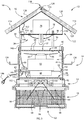
- Fig. 1 shows an insect trap assembly 10 according to the present invention.
- Insect trap assembly 10 includes a cover or a roof 12 that generally overlies a housing body or housing 14 and a trap or cage 16 that is removably connected to housing 14 and constructed to retain insects.
- Roof 12 includes an exterior surface 18 that is oriented to face an operating environment and an interior surface 20 that generally underlies exterior surface 18 and faces a top surface 22 of housing 14.
- Roof 12 is generally defined as a gable roof with sides that slope downward from a respective meeting point giving it an "A" shape. The angle in roof 12 directs rain and moisture off roof 12. It is appreciated that roof 12 may be defined by other styles of roofing, such as hipped, pyramidal, and gambrel or may have other less rectilinear shapes.
- roof 12 has solar cells 86 that provide power to the electrical elements, as described further below, of insect trap 10.
- the roof 12 has two roof planes or panels 114 that are generally rectangular in shape and that contain one or more solar cells 86.
- the plurality of solar cells 86 are arranged in straight rows to maximize the space on panels 114, however, it is appreciated that they may be arranged in any desired manner. It is appreciated that there may be a varying number of solar cells 86 and that they may be located anywhere on trap 10, such as on roof 12 or housing 14. It is also appreciated that roof 12 may have an integrated solar panel instead of a plurality of solar cells 86.
- the panels 114 are coupled to one another along a long edge 116 of the rectangular panels 114 by a hinged joint 134, such as a friction hinge or adhesive tape.
- joint 134 may be provided as a living hinge or a hinge assembly having one or more pins that cooperate with barrels or other pin receiving recesses associated with the respective panels 114.
- panels 114 may be coupled to one another at an edge that is not necessarily the "long edge” but rather, at any desired edge of the panel.
- the panels 114 are constructed of a durable metal material but it is appreciated that the panels may be constructed of other durable materials.
- the panels 114 are angled downward from long edge 116 to allow moisture to run past the roof 12 and fall past the housing 14.
- a flexible edge guard 120 overlaps the long edge 116 and is fixably attached to panels 114 so as to create a smooth appearance.
- An undercarriage frame 122 supports the two panels 114 from below.
- the frame 122 has a base 124 that corresponds to be fitted beneath the two panels 114 and which has a winged edge 126 which receives the short edges 128 of the rectangular panels 114.
- the frame 122 slidably receives the panels 114 within winged edge 126 to support the panels 114 at a given angle.
- the undercarriage frame 122 has a compartment or cylindrical body 130 disposed below frame 122 which may carry electrical components (not shown) and/or a light source 132. It is appreciated that cylindrical body 130 may contain collectors or rechargeable batteries (not shown) which collect the energy derived from solar cells 86 and store all or some of the energy for later usage. It is also appreciated that the energy derived from solar cells 86 may be used immediately instead of being stored.
- a number of posts 30 extend between interior surface 20 or more specifically, between cylindrical body 130 of roof 12 and top surface 22 of housing 14.
- Posts 30 are preferably spaced about a circumference associated with a radial perimeter 32 of top surface 22 of housing 14.
- Posts 30 define a gap 34 between interior surface 20 of roof 12 and top surface 22 of housing 14.
- gap 34 is shaped to allow insects to pass into the space between roof 12 and housing 14 and to be drawn and/or forced through the operational features of trap assembly 10. It is appreciated that although three posts 30 are shown, other numbers and/or arrangements of posts may be provided to create the offset or gap 34 between roof 12 and housing 14.
- the trap 10 preferably rests on a horizontal surface, however, it is appreciated that roof 12 may contain a hanging ring on its exterior surface 18 for hanging the trap 10 by a hook or other mounting apparatus. It is appreciated that there may be alternative ways to mount trap 10, such as by a pole stand or hung from a chain. It is also appreciated that the mounting means may be located at other areas of trap 10 besides the roof 12, such as on housing 14.
- the radial perimeter 32 of housing 14 receives posts 30 through corresponding receiving holes 36 spaced about a circumference associated with the radially positioning of posts 30.
- the posts 30 are fixed within holes 36 by an attachment means, such as bolts or screws 38, to prevent vertical movement of posts 30. It is contemplated that posts 30 may be fixed by other means, such as by welding or an adhesive.
- the posts 30 are extended downward into holes 36 to a depth that is able to receive an attachment means, such as screws 38.
- the radial perimeter 32 of top surface 22 of housing 14 is constructed of a reinforced plastic to provide radial strength to housing 14 and support for the weight of the upper elements.
- the radial perimeter 32 may be a sleeve 41 with a cavity 40 to receive the upper perimeter 42 of the housing 14 within the cavity 40.
- the sleeve 41 is slid over the upper perimeter 42 to receive the edge of the upper perimeter 42.
- the sleeve 41 may be fixedly attached to the housing body by bolts or screws 38, or other attachment means.
- the radial perimeter 32 may alternatively be defined by a piece that is attached parallel to the upper perimeter 42 by a fastening means, such as a bolt or screw.
- the radial perimeter 32 may be provided as either a piece separate from housing 14, or a reinforced edge of housing 14 itself.
- housing 14 is shown to have a generally cylindrical shape, it is appreciated that housing 14 could have any shape.
- a screen or a first protective screen 46 is disposed across the top surface 22 of housing 14.
- First protective screen 46 includes an exposed top surface 49 that faces the interior surface 20 of the roof 12 and a bottom surface 53 that underlies the top surface 49 and faces inwardly into the interior 84 of housing 14.
- the protective screen 46 is grated to provide for a plurality of preferably small openings 48 that allow air flow and small insects to pass through screen 46, but do not allow larger foreign objects to pass there beyond.
- the protective screen 46 is coupled to the inner wall 50 of the housing 14 and suspended over the entire top surface 22 of housing 14.
- insects attracted to the trap are drawn into the trap 10 through the gap 34 between posts 30 and enter the space between roof 12 and housing 14. Insects then enter the housing 14 by passing through the openings 48 of protective screen 46 and pass to the interior 84 of housing 14. The insects pass the operational features disposed in the interior 84 of housing 14 and exit the housing 14 by passing downward through a bottom base 52 of housing 14 and into the attached retaining cage 16.
- bottom base 52 of housing 14 has a generally cylindrical shape and corresponds to the shape of the housing 14 but widens in a concave manner to provide an expanding diameter orifice or opening 95. It is appreciated that bottom base 52 may be shaped in a number of ways and may not expand in diameter.
- the bottom base 52 is sized to overlap the upper perimeter 66 of retaining cage 16 to securely couple the housing 14 to the retaining cage 16.
- the bottom base 52 may also have a locking mechanism 54 consisting of locking holes 56 for receiving corresponding lock pieces 58 of the retaining cage 16.
- the retaining cage 16 is disposed below the housing 14 and fixably attached to capture insects exiting the bottom base 52 of housing 14. As insects exit bottom base 52, they are retained within the confines of cage 16.
- the cage 16 is a generally drum-shaped structure with an open top 60 and closed bottom 62. It is supported by a frame 64 that has an upper perimeter 66, lower perimeter 68, and connecting rods 70 that connect the upper 66 and lower 68 perimeters.
- the connecting rods 70 are preferably spaced about a circumference associated with a radial perimeter of cage 16.
- a mesh netting 72 is lined within the interior of the retaining cage 16 to cover the spaces 74 created between rods 70. The netting 72 prevents insects from escaping the retaining cage 16, allows visual inspection of the contents of the cage 16 by a user, and allows the air directed housing 14 to egress trap assembly 10.
- the edge guard 120 may be removed and one or more panels 114 may be lifted from base 124 to extend at an angle otherwise dissimilar from the angle of base 124.
- the hinge joint 134 provides frictional resistance to maintain panel 114 at a desired angle in order for the solar cells 86 to catch the UV light rays 138 at an appropriate angle to receive the most light contact.
- panel 114 may alternatively be held up mechanically or propped up by a rigid object. It is appreciated that movement of panels 114 may be done manually or electrically, and may be moved remotely or by a switch located on trap 10.
- the solar cells 86 are coupled to electrical components (not shown) that convert the solar energy to electrical energy to power the functional components of trap 10. It is contemplated that the light source 132 and fan assembly 82 may be powered by the solar energy retrieved from the solar cells 86, as may other electrical components of trap 10. The electrical components (not shown) may be connected to the functional components of trap 10 by an electrical wire 142. It is also contemplated that solar energy derived from solar cells 86 may be stored during periods when the sun's rays are at maximum strength. The solar energy may be stored by converting the energy to heat and storing it in collectors (not shown), e.g., flat plate collectors, focusing collectors, or passive collectors, that will store the energy for use when the sun is not shining or is obscured. It is also contemplated that the energy may be stored in other forms such as in a rechargeable battery 144 or the like. The rechargeable battery 144 has a charging capacity sufficient to energize trap 10 during periods when there is no source of UV light.
- the panels 114 may also be removed from base 124 and situated external to trap 10 to place panels 114 in a more favorable position for receiving UV light rays 138.
- frame 122 may be removed from roof 12 to situate base 122 and the supported panels 114 in a favorable position external to trap 10.
- the electrical connection between panels 114 and trap 10 may be reestablished by removing solar panel plug 152 from roof socket 154 and inserting the solar panel plug 154 into the lower socket 150 of trap housing 14. It is appreciated that an extension cord may be used to allow panels 114 to be situated further away from trap 10.
- an external solar energy source may collect energy via UV light, store the solar energy, and then provide supplemental energy to trap 100.
- the external solar energy collector may or may not be connected to the trap 10 at the time of collection, but would later be attached to the trap to provide energy to power the trap.
- trap assembly 10 may be powered by an external AC power supply 146 via the connection of AC plug 1 40 into lower socket 150 in trap housing 14. It is contemplated that trap assembly 10 may be powered by an external DC power supply and fitted with an AC/DC power adapter if necessary.
- the AC power supply 146 may provide power to the light source 132 and fan assembly 82, as well as other electrical components of trap 10 via electrical wire 142.
- trap assembly 10 is configured for operation with a number of optional attractants.
- One such attractant is the generation of light rays.
- a light assembly 76 is coupled to the base 124 by one or more mounting brackets 78.
- the mounting bracket 78 may be dome-shaped and allow for the attachment of one or more light bulbs 80.
- the mounting bracket may be attached to base 124 by an attachment means, such as bolts or screws 38. It is appreciated that there are alternative ways to mount light bulb 80 within the interior surface 20 of roof 12, and that the light assembly 76 may be mounted on different areas on the trap 10.
- the light assembly 76 is attached to a power source, preferably the electrical components (not shown) associated with solar cells 86, but may alternatively be attached to and powered by an AC power supply 146 or battery source 144. These power sources may be located on or in trap 10, or externally provided.
- An on-off switch 148 may assume either of two positions and accordingly make or break connections in a circuit to supply or terminate power to light assembly 76.
- Another attractant contemplated is carbon dioxide or a carbon dioxide releasing substance 81.
- the inner wall 50 of the housing is coated with a substance 81, such as titanium dioxide, which releases carbon dioxide when exposed to UV light rays. It is appreciated that other carbon dioxide releasing substances may be used as attractants to draw insects to the trap's vicinity. It is also appreciated that the substance may be coated at various locations on the trap, such as on base 124, on the interior surface 20 of roof 12, or on the exterior surface of housing 14 to name but a few.
- the water tray 136 may be removable or permanent and may be attached to the housing 14 via a number of methods, such as by screws or by being slidably fitted around a circumference or sidewall portion of housing 14.
- Insects that enter housing 14 by passing through the openings 48 of protective screen 46 pass through a number of operational features located in the interior 84 of housing 14.
- a fan assembly 82 which is fixably attached to the inner wall 50 of housing 1 4 by bolts 83, or the like, and suspended in the middle of the interior 84.
- the fan assembly 82 is attached to the inner wall 50 by a number of rigid suspension rods 88 that are bolted to inner wall 50 and attached to the bottom portion 85 of fan assembly 82.
- the suspension rods 88 are located so that they do not interfere with movement of blades 90 of the fan assembly 82.
- the fan assembly 82 has rotatable blades 90 that preferably rotate in a horizontal plane that is aligned between the first protective screen 46 and a second protective screen 91. It is contemplated that blades 90 may be provided at different pitches in order to create the desired air flow or vacuum effect. It is also contemplated that the fan assembly 82 may be located at different locations within the interior 84 of housing 14. That is fan assembly 82 need not be centrally located and/or can be disposed nearer one of screens 46, 91.
- the fan assembly 82 is attached to a power source, preferably the electrical components associated with solar cells 86 via electrical wire 142, but may alternatively be attached to and powered by an AC power supply 146 or battery source 144. These power sources may be located on or in trap 10, or externally provided.
- On-off switch 148 may assume either of two positions and accordingly make or break connections in a circuit to supply or remove power to fan assembly 82.
- Second protective screen 91 is disposed below fan assembly 82 and includes an upper surface 93 that faces inwardly toward the housing interior 84 and a bottom surface 92 that generally underlies upper surface and faces a damper assembly 96.
- Protective screen 91 is grated to provide for a plurality of small openings 94 that allow air flow and insects to pass through the openings 94.
- the protective screen 91 is coupled to the inner wall 50 of the housing 14 and is suspended over the entire bottom opening 95 of the housing 14. Screen 91 prevents unintended objects from inadvertently passing into housing 14 but is constructed to allow insects to pass fairly unobstructed therethrough.
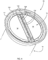
- a damper assembly 96 is coupled to bottom base 52.
- Damper assembly 96 includes two damper flaps 98 that each independently rotate between open and closed positions.
- the damper flaps 98 are preferably semi-circular to collectively cover the circular opening 95.
- damper flaps 98 are in a closed position and cover the bottom opening 95 of the housing 14 to prevent insects from escaping retaining cage 16.
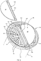
- damper flaps 98 are in an open position and provide a space 99 to allow insects to be passed into the retaining cage 16.
- the damper flaps 98 In an open position, the damper flaps 98 extend to a position that is preferably less than ninety degrees and extend outwardly into the attached retaining cage 16. Full extension of the damper flaps 98 is limited by stop-bars 100 which provide support and prohibit movement of the flaps 98. Air flow past the open oriented damper flaps 98 prevents the egress of insects contained in cage 16.
- the damper flaps 98 are attached to the inside wall 102 of bottom base 52 by pivot pins 104 that are attached inwardly from the straight edge 108 of flaps 98.
- weighted rods 106 which are preferably made of a metal material, to create a desired weighted balance of each flap 98.
- weighted rods 106 may be made of any weighted material. Regardless of the material they are constructed of, rods 106 are orientated relative to the respective flap 98 and pivot pins 104 to bias the respective flap toward the closed position.
- the damper flaps 98 align at their straight edges 108 to completely conceal the opening 95 and prevent insects from escaping the retaining cage 16 when no air flow is directed therethrough.
- the weighted rods 106 at the straight edge 1 08 of the flaps 98 bias the flaps 98 toward a closed position when no air is flowing through the trap.
- the flap 98 when the damper flap 98 is in an open position, the flap 98 is rotated about pivot pin 104 to dispose flap 98 at an angle that is preferably less than ninety degrees relative to the closed position and less than center with respect to the axis defined by the pivot 104 and the center of gravity of the flap 98.
- the flap 98 is prevented from extending further by stop-bar 100 which is disposed directly behind flap 98 and is fixably attached to the inside wall 102 of bottom base 52.
- notch 110 located on stop-bar 100 abuts flap 98 to prevent further rotation. This disposition provides space 99 which allows insects to pass outwardly from housing 14 and into the retaining cage 16.
- the locking mechanism 54 of the bottom base 52 to the retaining cage 16 consists of holes 56 at the bottom base which receive the corresponding lock pieces 58 of the top of the retaining cage 16.
- the lock pieces 58 are fitted within holes 56.
- the user then rotates the bottom base 52 and retaining cage 16 in opposite directions to secure the locking pieces 58 within holes 56.
- lock pieces 58 are unable to slide out of holes 56.
- the user rotates the bottom base 52 and the retaining cage in opposite rotational directions as used to secure.
- the lock pieces 58 are then permitted to slide out of holes 56 and the retaining cage 16 can be removed from the bottom base 52 for cleaning, or the like.
Landscapes
- Life Sciences & Earth Sciences (AREA)
- Pest Control & Pesticides (AREA)
- Engineering & Computer Science (AREA)
- Insects & Arthropods (AREA)
- Wood Science & Technology (AREA)
- Zoology (AREA)
- Environmental Sciences (AREA)
- Catching Or Destruction (AREA)
Claims (11)
- Solarbetriebene Insektenfalle (10), umfassend:
ein Gehäuse, das Folgendes umfasst:ein Solarpaneldach (12), das ein erstes Panel und ein zweites Panel (114) umfasst, die durch ein Gelenk (134) flexibel aneinander gekoppelt sind und durch eine äußere Oberfläche (18) und eine innere Oberfläche (20) definiert sind, wobei die äußere Oberfläche des ersten Panels und des zweiten Panels (114) eine Vielzahl von Solarzellen (86) zur Stromversorgung von mindestens einer elektrischen Komponente der Insektenfalle (10) trägt;einen Gehäusekörper (14), der unter dem Solarpaneldach (12) nach unten ragt, wobei der Gehäusekörper (14) durch eine offene Oberseite (49), eine Innenfläche (50) und eine offene Unterseite (95) definiert ist; undeinen Käfig (16), der abnehmbar an die Unterseite des Gehäusekörpers angebracht ist und durch eine offene Oberseite (60), eine Innenfläche (72) und eine geschlossene Unterseite (62) definiert ist;eine Lichtquelle (132), die in Bezug auf das Dach (12) getragen wird;eine Lüfterbaugruppe (82), die in Bezug auf die Innenfläche (50) des Gehäusekörpers (14) getragen wird und einen drehbaren Lüfterflügel (90) beinhaltet, der konfiguriert ist, um Luft durch den Gehäusekörper (14) in eine Richtung von der offenen Oberseite (22) zur Lüfterbaugruppe (82) hin zu saugen; undeine Dämpferbaugruppe (96), die in Bezug auf den Gehäusekörper (14) unter der Lüfterbaugruppe (82) getragen wird, wobei die Dämpferbaugruppe (96) Folgendes umfasst:eine erste und eine zweite Dämpferabschirmung (98), wobei jede Dämpferabschirmung eine im Allgemeinen halbkreisförmige planare Form aufweist, undeine Kopplungsanordnung (104), die unabhängig jede der ersten und zweiten Dämpferabschirmung (98) in Bezug auf den Gehäusekörper (14) koppelt, sodass jede Dämpferabschirmung (98) in Bezug auf den Gehäusekörper (14) drehbar getragen wird, sodass die erste und zweite Dämpferabschirmung zu einer geschlossenen Position hin schwingen, wenn der Lüfter (82) ausgeschaltet ist und zu einer offenen Position hin schwingen, wenn der Lüfter (82) eingeschaltet ist. - Insektenfalle nach Anspruch 1, wobei das Gehäuse ferner einen Tragrahmen (122) umfasst, der durch eine obere Fläche und eine untere Fläche definiert ist, wobei die obere Fläche das erste und zweite Panel (114) aufnimmt.
- Insektenfalle nach Anspruch 2, wobei die obere Fläche des Tragrahmens (122) Flügel (126) auf den distalen Enden aufweist, die zur Aufnahme von entsprechenden distalen Enden des ersten und zweiten Panels (114) konfiguriert sind, wobei sich das erste und zweite Panel (114) über die Flügel (126) des Tragrahmens (122) hinaus erstrecken, um ungehinderte Abtropfkanten an den distalen Kanten des ersten und zweiten Panels (114) bereitzustellen.
- Insektenfalle nach Anspruch 1, ferner umfassend:ein erstes Sieb (46), das über der offenen Oberseite (49) des Gehäusekörpers (14) angeordnet ist, wobei das erste Sieb (46) eine Vielzahl von Durchlässen (48) aufweist, die jeweils geformt sind, um es Luft und Insekten zu ermöglichen, das erste Sieb (46) zu passieren; undein zweites Sieb (91), das über der offenen Unterseite (95) des Gehäusekörpers (14) angeordnet ist, wobei das zweite Sieb (91) eine Vielzahl von Durchlässen (94) aufweist, die jeweils geformt sind, um es Luft und Insekten zu ermöglichen, das zweite Sieb (91) zu passieren.
- Insektenfalle nach Anspruch 1, wobei die Kopplungsanordnung der Dämpferbaugruppe (96) einen Satz von Drehzapfen (104) beinhaltet und jeder Drehzapfen nahe einer linearen Seite (108) der im Allgemeinen halbkreisförmigen planaren Form einer entsprechenden der ersten und der zweiten Dämpferabschirmung (98) angeordnet ist.
- Insektenfalle nach Anspruch 1, ferner umfassend einen Lockstoff (81), der auf der Innenfläche (50) des Gehäusekörpers (14) angeordnet ist und konfiguriert ist, um Kohlendioxid freizusetzen.
- Insektenfalle nach Anspruch 1, ferner umfassend eine externe Energiequelle (144, 146), die abnehmbar an der Falle (10) befestigt werden kann, um eine alternative Energie an die Falle (10) zu liefern.
- Insektenfalle nach Anspruch 7, wobei die externe Energieversorgung eine Energiespeichervorrichtung (144) ist.
- Insektenfalle nach Anspruch 7, wobei die externe Energieversorgung (144) von Solarenergie abgeleitete Energie ist.
- Insektenfalle nach Anspruch 1, ferner umfassend eine elektrische Verbindung (142) zwischen der Vielzahl von Solarzellen (86) und mindestens einer von der Lichtquelle (132) und der Lüfterbaugruppe (82).
- Verfahren zum Fangen von Insekten, umfassend die folgenden Schritte:Bereitstellen der solarbetriebenen Insektenfalle (10) nach einem der vorhergehenden Ansprüche; undBetreiben von mindestens einer von der Lichtquelle (132) und der Lüfterbaugruppe (82) unter Verwendung von Energie, die von den Solarzellen abgeleitet ist.
Applications Claiming Priority (2)
| Application Number | Priority Date | Filing Date | Title |
|---|---|---|---|
| US13/719,447 US9326497B2 (en) | 2012-12-19 | 2012-12-19 | Solar powered insect trap |
| PCT/US2013/057477 WO2014099051A1 (en) | 2012-12-19 | 2013-08-30 | Solar powered insect trap |
Publications (3)
| Publication Number | Publication Date |
|---|---|
| EP2934108A1 EP2934108A1 (de) | 2015-10-28 |
| EP2934108A4 EP2934108A4 (de) | 2016-08-17 |
| EP2934108B1 true EP2934108B1 (de) | 2019-05-01 |
Family
ID=50929273
Family Applications (1)
| Application Number | Title | Priority Date | Filing Date |
|---|---|---|---|
| EP13864617.9A Active EP2934108B1 (de) | 2012-12-19 | 2013-08-30 | Solarbetriebene insektenfalle |
Country Status (4)
| Country | Link |
|---|---|
| US (1) | US9326497B2 (de) |
| EP (1) | EP2934108B1 (de) |
| ES (1) | ES2730003T3 (de) |
| WO (1) | WO2014099051A1 (de) |
Cited By (1)
| Publication number | Priority date | Publication date | Assignee | Title |
|---|---|---|---|---|
| CN110521710A (zh) * | 2019-09-24 | 2019-12-03 | 杭州卫康有害生物防治有限公司 | 一种土壤病虫害防治装置 |
Families Citing this family (91)
| Publication number | Priority date | Publication date | Assignee | Title |
|---|---|---|---|---|
| SG11201506734QA (en) | 2013-03-01 | 2015-09-29 | Arthropod Biosciences Llc | Insect trap device and method of using |
| CN104430262B (zh) * | 2013-09-25 | 2019-07-05 | 荣金集团有限公司 | 昆虫诱捕器 |
| JP6616301B2 (ja) | 2013-11-27 | 2019-12-04 | アースロポッド バイオサイエンシーズ エルエルシー | 捕虫装置とその使用方法 |
| CN112616791B (zh) * | 2014-04-26 | 2023-06-16 | 宝洁公司 | 昆虫诱捕装置及使用方法 |
| US9717228B2 (en) * | 2014-07-24 | 2017-08-01 | Seoul Viosys Co., Ltd. | Insect trap using UV LED lamp |
| US9706764B2 (en) * | 2014-07-24 | 2017-07-18 | Seoul Viosys Co., Ltd. | Insect trap using UV LED lamp |
| FR3024643B1 (fr) * | 2014-08-07 | 2016-09-09 | Techno Bam | Appareil et procede pour prendre au piege des insectes volants nuisibles. |
| CN104229351A (zh) * | 2014-09-10 | 2014-12-24 | 李梦雯 | 一种具有捕虫功能的太阳能垃圾收集箱 |
| CN104390166A (zh) * | 2014-12-08 | 2015-03-04 | 苏州科利亚照明科技有限公司 | 一种带有杀虫功能的led与oled新型混合照明灯 |
| HK1243595A1 (zh) | 2015-01-12 | 2018-07-20 | 宝洁公司 | 昆虫诱捕装置及使用方法 |
| CN104839121B (zh) * | 2015-03-27 | 2017-03-01 | 湖北恒生源电子股份有限公司 | 一种太阳能智能杀虫灯 |
| USD777291S1 (en) | 2015-05-28 | 2017-01-24 | Dynamic Solutions Worldwide, LLC | Insect trap housing |
| CN113243348B (zh) | 2015-05-29 | 2023-06-02 | 艺康美国股份有限公司 | 用于吸引和诱捕飞虫的装置和方法 |
| US10021871B1 (en) * | 2015-06-05 | 2018-07-17 | Thomas Paul Cogley | Mobile insect killing system |
| US10091980B1 (en) * | 2015-06-05 | 2018-10-09 | Thomas Paul Cogley | Bed bug detector system |
| US10091981B1 (en) * | 2015-06-05 | 2018-10-09 | Thomas Paul Cogley | Flea destructor system |
| US10021869B1 (en) * | 2015-06-05 | 2018-07-17 | Thomas Paul Cogley | Mosquito destructor system |
| CN104938458A (zh) * | 2015-07-08 | 2015-09-30 | 安徽海澄德畅电子科技有限公司 | 一种杀虫装置的旋转组件 |
| CN105284637A (zh) * | 2015-10-21 | 2016-02-03 | 耒阳市兴农牧业有限公司 | 一种畜牧养殖大棚用驱蚊灯 |
| BR112016022131B1 (pt) * | 2016-03-14 | 2022-01-04 | Seoul Viosys Co., Ltd | Armadilha para insetos |
| CN105775506A (zh) * | 2016-04-27 | 2016-07-20 | 常州绿尚鲜网络科技有限公司 | 光引诱粘杀与风杀蚊蝇复合型垃圾箱 |
| USD818559S1 (en) | 2016-05-20 | 2018-05-22 | Ecolab Usa Inc. | Insect trap |
| CN205884470U (zh) * | 2016-08-05 | 2017-01-18 | 宁波大央工贸有限公司 | 一种具有灭蚊功能的无叶风扇 |
| CN106489871A (zh) * | 2016-09-24 | 2017-03-15 | 东莞市安零模具科技有限公司 | 水帘式诱捕器 |
| CN106489874A (zh) * | 2016-09-24 | 2017-03-15 | 东莞市青平电子科技有限公司 | 多面聚能灭蚊灯 |
| CN106489870A (zh) * | 2016-09-24 | 2017-03-15 | 东莞市安零模具科技有限公司 | 蚊虫捕杀器 |
| CN106489875A (zh) * | 2016-09-24 | 2017-03-15 | 东莞市青平电子科技有限公司 | 太阳能灭蚊灯 |
| CN106489872A (zh) * | 2016-09-24 | 2017-03-15 | 东莞市安零模具科技有限公司 | 物理诱捕器 |
| CN106614450A (zh) * | 2016-09-24 | 2017-05-10 | 东莞市青平电子科技有限公司 | 昆虫捕杀器 |
| CN106359336A (zh) * | 2016-11-20 | 2017-02-01 | 李红光 | 一种果园电器 |
| US20180255761A1 (en) * | 2016-11-21 | 2018-09-13 | John J. Paoluccio | Aquatic organism treatment method and apparatus |
| TWI603675B (zh) * | 2016-12-16 | 2017-11-01 | 國立高雄應用科技大學 | 捕蚊裝置 |
| US10271533B2 (en) * | 2017-01-23 | 2019-04-30 | Lighting Science Group Corporation | Smart mosquito trap |
| WO2018230007A1 (ja) * | 2017-06-16 | 2018-12-20 | シャープ株式会社 | 送風装置 |
| US10827737B2 (en) * | 2017-06-19 | 2020-11-10 | Rebecca King | Flying insect catching apparatus |
| GB2566036B (en) * | 2017-08-30 | 2020-06-24 | Brandenburg Innovation Ltd | An ovitrap and method of controlling vector borne disease |
| US10980224B2 (en) * | 2017-10-12 | 2021-04-20 | Sterling International Inc. | Pillar device for adhesive insect capture with bird guards |
| CN107889805A (zh) * | 2017-11-23 | 2018-04-10 | 恭城福茂生油茶文化产业发展有限公司 | 一种农田用太阳能蚊虫灯 |
| CN107751150A (zh) * | 2017-11-23 | 2018-03-06 | 恭城福茂生油茶文化产业发展有限公司 | 一种多功能农田用太阳能蚊虫灯 |
| US10791726B2 (en) * | 2017-11-28 | 2020-10-06 | Ningbo Dayang Industry And Trade Co., Ltd. | Mosquito-killing device |
| WO2019127544A1 (zh) * | 2017-12-29 | 2019-07-04 | 深圳前海小有技术有限公司 | 捕虫器 |
| CA2995537A1 (en) * | 2018-02-16 | 2019-08-16 | Maxtech Mosquito Control Inc. | Smart bulb |
| US20190297868A1 (en) * | 2018-02-17 | 2019-10-03 | Shane Patrick Warner | Trap System For Insects |
| US10750733B1 (en) | 2018-02-28 | 2020-08-25 | Espen Garner | Autonomous insect carrier |
| US20190263518A1 (en) * | 2018-02-28 | 2019-08-29 | Espen Garner | Unmanned Aerial Vehicle Having an Insect Trap |
| US10772314B1 (en) * | 2018-06-27 | 2020-09-15 | Edward Caba | Pest trap |
| CN112970691B (zh) * | 2018-06-28 | 2023-06-23 | 北京环六环环保科技有限公司 | 一种野营使用的诱虫设备及使用方法 |
| TWI671007B (zh) * | 2018-06-29 | 2019-09-11 | 國立高雄科技大學 | 全域式二次uvled元件捕蚊裝置 |
| EP3836782B1 (de) * | 2018-08-01 | 2026-01-14 | Romanova, Anastasiia Romanivna | Umweltfreundliches system zur bekämpfung von mücken |
| CN109169570B (zh) * | 2018-10-23 | 2021-07-16 | 嵊州市观东机械厂 | 一种农林业兼用的害虫诱捕收集装置 |
| US10736309B1 (en) * | 2018-11-27 | 2020-08-11 | Thomas Paul Cogley | Bed bug detector system |
| CN109819969A (zh) * | 2019-01-21 | 2019-05-31 | 贵州省生物研究所 | 一种牛蛙诱捕装置 |
| US10925274B2 (en) * | 2019-02-06 | 2021-02-23 | Satish K. CHerukumalli | Smart trap for mosquito classification |
| IT201900002379A1 (it) * | 2019-02-19 | 2020-08-19 | Locati S R L | Dispositivo per la cattura di insetti. |
| US11134672B1 (en) | 2019-03-19 | 2021-10-05 | Ronald D. Warren | Bug repellent system |
| CN109953004A (zh) * | 2019-04-11 | 2019-07-02 | 缪一诺 | 一种农业保护庄稼用灭虫装置 |
| CN110583598A (zh) * | 2019-10-30 | 2019-12-20 | 临海市启致灯具有限公司 | 一种智能捕虫草坪地灯 |
| CN212116770U (zh) * | 2019-12-30 | 2020-12-11 | 宁波大央科技有限公司 | 一种虫子诱捕器 |
| USD914128S1 (en) | 2020-03-03 | 2021-03-23 | Sterling International Inc. | End cap for an insect trap |
| USD915544S1 (en) | 2020-03-03 | 2021-04-06 | Sterling International Inc. | Bird guard for an insect trap |
| RU199559U1 (ru) * | 2020-06-29 | 2020-09-08 | Федеральное государственное бюджетное научное учреждение «Всероссийский научно-исследовательский институт биологической защиты растений" | Аспирационная световая ловушка для насекомых |
| CN213177767U (zh) * | 2020-07-02 | 2021-05-11 | 唐伟 | 灭蚊野营灯 |
| US20220022441A1 (en) * | 2020-07-24 | 2022-01-27 | Ap&G Co., Inc. | Flying insect trap with enhanced illumination |
| CN111972373A (zh) * | 2020-08-27 | 2020-11-24 | 扬州市宝迪照明科技有限公司 | 一种复合式太阳能杀虫灯 |
| CN111878442A (zh) * | 2020-09-11 | 2020-11-03 | 珠海格力电器股份有限公司 | 摇头装置及风扇 |
| CN112314549B (zh) * | 2020-10-21 | 2022-08-16 | 湖南助农农业科技发展有限公司 | 一种稻虾养殖用害虫防治装置 |
| US20220132824A1 (en) * | 2020-10-30 | 2022-05-05 | 19 Thrasio Nineteen, Inc. | Insect capture device |
| CN214102884U (zh) * | 2020-12-02 | 2021-09-03 | 浙江硕而博科技股份有限公司 | 一种灭蚊灯 |
| CN112715503B (zh) * | 2020-12-28 | 2022-09-30 | 蒙阴县林业局 | 一种林业用全方位防虫害诱捕装置 |
| US20220248654A1 (en) * | 2021-02-08 | 2022-08-11 | Stratex Partners LLC | Insect trap assembly and method of use |
| US11284610B1 (en) * | 2021-03-17 | 2022-03-29 | Howard Sowers | System and method for a mosquito trap |
| CN113303302A (zh) * | 2021-06-30 | 2021-08-27 | 四川上太科技有限公司 | 一种自动捕虫器 |
| US12004500B1 (en) * | 2021-08-26 | 2024-06-11 | Paul Liotta | Fly trap device and method of use |
| USD990613S1 (en) * | 2021-09-09 | 2023-06-27 | Yan Liu | Mosquito killer |
| CN113892469B (zh) * | 2021-09-26 | 2022-09-09 | 湖南省林业科学院 | 一种用于园林内的诱虫装置 |
| CN113812385A (zh) * | 2021-10-14 | 2021-12-21 | 怀化市正泰农机装备有限公司 | 一种便携式吸风捕虫器 |
| US12302885B2 (en) * | 2021-10-18 | 2025-05-20 | Woodstream Corporation | Insect trap receptacle |
| CN114097743B (zh) * | 2021-11-11 | 2023-09-05 | 重庆仓泉环境科技有限公司 | 一种基于智能农业的趋光性害虫捕杀装置 |
| WO2023105998A1 (ja) * | 2021-12-09 | 2023-06-15 | シャープ株式会社 | 送風装置 |
| US20250057141A1 (en) * | 2022-01-12 | 2025-02-20 | Woodstream Corporation | Moth screen for insect traps |
| US11603970B1 (en) | 2022-01-18 | 2023-03-14 | E. Mishan & Sons, Inc. | Solar lamp with insect control trap |
| USD985821S1 (en) | 2022-01-18 | 2023-05-09 | E. Mishan & Sons, Inc. | Solar lamp |
| EP4223117A1 (de) * | 2022-02-04 | 2023-08-09 | Biogents Aktiengesellschaft | Insektenfangvorrichtung und verfahren zum fangen von fliegenden insekten |
| CN114680087A (zh) * | 2022-03-25 | 2022-07-01 | 苏州市农业科学院 | 一种基于区块链的智慧茶园管理用虫情监测装置及方法 |
| CN114709727B (zh) * | 2022-04-27 | 2025-03-14 | 深圳市中电通科技实业有限公司 | 一种便于调节易使用的配电柜 |
| CN116098134A (zh) * | 2022-11-07 | 2023-05-12 | 宁夏回族自治区中卫山羊选育场 | 一种羊养殖用蚊虫灭杀装置 |
| UA129734C2 (uk) * | 2022-12-30 | 2025-07-16 | Анастасія Романівна Романова | Пастка для комах |
| USD1045010S1 (en) * | 2023-05-11 | 2024-10-01 | Changhui Qian | Bug zapper |
| US12274254B2 (en) * | 2023-08-07 | 2025-04-15 | Meizhen LI | Solar mosquito killer lamp |
| ES3049810T3 (en) * | 2023-08-18 | 2025-12-18 | Foshan Greenyellow Electric Tech Co Ltd | Mosquito trap |
| CN117581840A (zh) * | 2023-10-30 | 2024-02-23 | 新疆生产建设兵团第七师农业科学研究所 | 一种棉铃虫防控用节能型诱捕装置 |
Family Cites Families (28)
| Publication number | Priority date | Publication date | Assignee | Title |
|---|---|---|---|---|
| US1693368A (en) * | 1927-11-04 | 1928-11-27 | Effie May Cherry | Mosquito and insect trap |
| US3201893A (en) * | 1963-09-03 | 1965-08-24 | Gen Electric | Insect trap |
| US4282673A (en) * | 1979-06-21 | 1981-08-11 | Focks Dana A | Flying insect trap |
| US4903637A (en) * | 1988-06-07 | 1990-02-27 | Devault Jack D | Foldable house and carrier for small pets |
| US4959923A (en) | 1989-04-14 | 1990-10-02 | S. C. Johnson & Son, Inc. | Electronic insect trap |
| US5259153A (en) | 1990-07-19 | 1993-11-09 | Olive Billy B | Light energized insect trap |
| US5280684A (en) | 1991-08-05 | 1994-01-25 | Filonczuk Michael A | Insect killing receptacle cover |
| CA2050234C (en) | 1991-08-29 | 1995-12-26 | Luc Jobin | Portable luminous insect trap |
| US5157865A (en) * | 1991-10-03 | 1992-10-27 | Chang Che Yuan | Cantilever type mosquito catcher |
| US5347748A (en) | 1993-08-16 | 1994-09-20 | The United States Of America As Represented By The Secretary Of The Agriculture | Livestock walk-through fly trap |
| US5634292A (en) | 1993-10-29 | 1997-06-03 | Kitterman; Roger L. | Apparatus and method for attracting and trapping insects |
| IL107721A (en) | 1993-11-23 | 1996-07-23 | Haim Hazan | Device for destroying insects |
| US6570494B1 (en) | 1999-12-01 | 2003-05-27 | Kenneth Charles Leftridge, Sr. | Mosquito guard |
| US6436283B1 (en) * | 2000-03-07 | 2002-08-20 | Eddie D. Duke | Portable rainwater collecting and purifying system |
| KR20020021466A (ko) * | 2000-09-15 | 2002-03-21 | 이경원, 김윤환 | 공기 정화 기능의 모기 퇴치기 |
| US20050060926A1 (en) * | 2001-07-20 | 2005-03-24 | Kyeong-Won Lee | Mosquito attracting and killing apparatus with air cleaning function |
| US6502347B1 (en) | 2002-02-06 | 2003-01-07 | Alex Smith | Lighted insect trap |
| WO2004036989A1 (en) | 2002-10-18 | 2004-05-06 | American Biophysics Corp. | System for trapping flying insects and a method for making the same |
| US6817139B1 (en) * | 2003-01-13 | 2004-11-16 | William E. Powell | Bug killing system |
| US7073287B2 (en) | 2004-09-13 | 2006-07-11 | Leung Fai Lau | Mosquitoes eradicating system |
| US7281350B2 (en) | 2005-03-08 | 2007-10-16 | Wilbanks Alvin D | Mosquito/insect larva trap magnet system |
| CN2838282Y (zh) | 2005-11-14 | 2006-11-22 | 苗胜江 | 一种太阳能灭虫器装置 |
| US7308774B2 (en) | 2006-01-05 | 2007-12-18 | Aleague International Co. | Solar insect killer and catcher |
| US20080010896A1 (en) | 2006-07-11 | 2008-01-17 | Chin Kuo Lin | Solar Powered Insect Trapping and Terminating Apparatus |
| US20080072833A1 (en) * | 2006-09-06 | 2008-03-27 | John Meeks | Outdoor pet litter box |
| US8479438B1 (en) * | 2010-08-04 | 2013-07-09 | Vincent J. Wilhelmi | Arthropod abatement device |
| US8424239B1 (en) * | 2010-10-12 | 2013-04-23 | Jose A. Gallo | Codling moth trap |
| US9049855B2 (en) * | 2012-11-19 | 2015-06-09 | Dynamic Solutions Worldwide, LLC. | Insect trap having an air-actuated damper |
-
2012
- 2012-12-19 US US13/719,447 patent/US9326497B2/en active Active
-
2013
- 2013-08-30 ES ES13864617T patent/ES2730003T3/es active Active
- 2013-08-30 EP EP13864617.9A patent/EP2934108B1/de active Active
- 2013-08-30 WO PCT/US2013/057477 patent/WO2014099051A1/en not_active Ceased
Non-Patent Citations (1)
| Title |
|---|
| None * |
Cited By (2)
| Publication number | Priority date | Publication date | Assignee | Title |
|---|---|---|---|---|
| CN110521710A (zh) * | 2019-09-24 | 2019-12-03 | 杭州卫康有害生物防治有限公司 | 一种土壤病虫害防治装置 |
| CN110521710B (zh) * | 2019-09-24 | 2021-07-02 | 杭州卫康有害生物防治有限公司 | 一种土壤病虫害防治装置 |
Also Published As
| Publication number | Publication date |
|---|---|
| EP2934108A4 (de) | 2016-08-17 |
| ES2730003T3 (es) | 2019-11-07 |
| US20140165452A1 (en) | 2014-06-19 |
| WO2014099051A1 (en) | 2014-06-26 |
| US9326497B2 (en) | 2016-05-03 |
| EP2934108A1 (de) | 2015-10-28 |
Similar Documents
| Publication | Publication Date | Title |
|---|---|---|
| US9326497B2 (en) | Solar powered insect trap | |
| EP2919583B1 (de) | Insektenfalle mit einem luftbetätigten dämpfer | |
| KR102603570B1 (ko) | 지주부착형 해충유인 포획장치 | |
| JP3136423U (ja) | 害虫捕獲器 | |
| CN106508848A (zh) | 一种风吸撞击组合式杀虫灯 | |
| JP3141997U (ja) | 害虫捕獲器 | |
| CN206612061U (zh) | 一种捕虫装置 | |
| CN104229351A (zh) | 一种具有捕虫功能的太阳能垃圾收集箱 | |
| KR100753435B1 (ko) | 해충 포집장치 | |
| CN211353646U (zh) | 一种太阳能风吸式杀虫灯 | |
| CN115104584B (zh) | 一种林业害虫诱捕设备 | |
| CN200983801Y (zh) | 电子吸蚊机 | |
| CN208956778U (zh) | 一种太阳能led杀虫灯 | |
| CN110762469A (zh) | 具有灭蚊虫功能的太阳能路灯 | |
| CN206472687U (zh) | 一种风吸撞击组合式杀虫灯 | |
| CN107152656A (zh) | 一种具有捕虫功能的太阳能草坪灯 | |
| CN108887245A (zh) | 一种太阳能led杀虫灯 | |
| CN215454860U (zh) | 农业害虫诱捕器 | |
| CN206213077U (zh) | 一种灭蚊灯 | |
| CN211475794U (zh) | 一种新型可驱蚊的太阳能灯具 | |
| KR200407272Y1 (ko) | 흡입식 포충기 | |
| CN210382338U (zh) | 一种多功能昆虫诱捕器 | |
| CN210203017U (zh) | 一种用于仓库和田间的诱虫板 | |
| CN219288526U (zh) | 一种烟草病虫防治装置 | |
| JP2001155509A (ja) | 捕虫機能付照明器具 |
Legal Events
| Date | Code | Title | Description |
|---|---|---|---|
| PUAI | Public reference made under article 153(3) epc to a published international application that has entered the european phase |
Free format text: ORIGINAL CODE: 0009012 |
|
| 17P | Request for examination filed |
Effective date: 20150708 |
|
| AK | Designated contracting states |
Kind code of ref document: A1 Designated state(s): AL AT BE BG CH CY CZ DE DK EE ES FI FR GB GR HR HU IE IS IT LI LT LU LV MC MK MT NL NO PL PT RO RS SE SI SK SM TR |
|
| AX | Request for extension of the european patent |
Extension state: BA ME |
|
| DAX | Request for extension of the european patent (deleted) | ||
| A4 | Supplementary search report drawn up and despatched |
Effective date: 20160714 |
|
| RIC1 | Information provided on ipc code assigned before grant |
Ipc: F03G 6/00 20060101ALI20160708BHEP Ipc: A01M 1/10 20060101ALI20160708BHEP Ipc: A01M 1/08 20060101AFI20160708BHEP Ipc: A01M 1/02 20060101ALI20160708BHEP |
|
| GRAP | Despatch of communication of intention to grant a patent |
Free format text: ORIGINAL CODE: EPIDOSNIGR1 |
|
| STAA | Information on the status of an ep patent application or granted ep patent |
Free format text: STATUS: GRANT OF PATENT IS INTENDED |
|
| INTG | Intention to grant announced |
Effective date: 20181126 |
|
| GRAS | Grant fee paid |
Free format text: ORIGINAL CODE: EPIDOSNIGR3 |
|
| GRAA | (expected) grant |
Free format text: ORIGINAL CODE: 0009210 |
|
| STAA | Information on the status of an ep patent application or granted ep patent |
Free format text: STATUS: THE PATENT HAS BEEN GRANTED |
|
| AK | Designated contracting states |
Kind code of ref document: B1 Designated state(s): AL AT BE BG CH CY CZ DE DK EE ES FI FR GB GR HR HU IE IS IT LI LT LU LV MC MK MT NL NO PL PT RO RS SE SI SK SM TR |
|
| REG | Reference to a national code |
Ref country code: GB Ref legal event code: FG4D |
|
| REG | Reference to a national code |
Ref country code: CH Ref legal event code: EP Ref country code: AT Ref legal event code: REF Ref document number: 1125688 Country of ref document: AT Kind code of ref document: T Effective date: 20190515 |
|
| REG | Reference to a national code |
Ref country code: DE Ref legal event code: R096 Ref document number: 602013054818 Country of ref document: DE |
|
| REG | Reference to a national code |
Ref country code: IE Ref legal event code: FG4D |
|
| REG | Reference to a national code |
Ref country code: NL Ref legal event code: MP Effective date: 20190501 |
|
| REG | Reference to a national code |
Ref country code: LT Ref legal event code: MG4D |
|
| PG25 | Lapsed in a contracting state [announced via postgrant information from national office to epo] |
Ref country code: PT Free format text: LAPSE BECAUSE OF FAILURE TO SUBMIT A TRANSLATION OF THE DESCRIPTION OR TO PAY THE FEE WITHIN THE PRESCRIBED TIME-LIMIT Effective date: 20190901 Ref country code: NL Free format text: LAPSE BECAUSE OF FAILURE TO SUBMIT A TRANSLATION OF THE DESCRIPTION OR TO PAY THE FEE WITHIN THE PRESCRIBED TIME-LIMIT Effective date: 20190501 Ref country code: SE Free format text: LAPSE BECAUSE OF FAILURE TO SUBMIT A TRANSLATION OF THE DESCRIPTION OR TO PAY THE FEE WITHIN THE PRESCRIBED TIME-LIMIT Effective date: 20190501 Ref country code: AL Free format text: LAPSE BECAUSE OF FAILURE TO SUBMIT A TRANSLATION OF THE DESCRIPTION OR TO PAY THE FEE WITHIN THE PRESCRIBED TIME-LIMIT Effective date: 20190501 Ref country code: LT Free format text: LAPSE BECAUSE OF FAILURE TO SUBMIT A TRANSLATION OF THE DESCRIPTION OR TO PAY THE FEE WITHIN THE PRESCRIBED TIME-LIMIT Effective date: 20190501 Ref country code: HR Free format text: LAPSE BECAUSE OF FAILURE TO SUBMIT A TRANSLATION OF THE DESCRIPTION OR TO PAY THE FEE WITHIN THE PRESCRIBED TIME-LIMIT Effective date: 20190501 Ref country code: NO Free format text: LAPSE BECAUSE OF FAILURE TO SUBMIT A TRANSLATION OF THE DESCRIPTION OR TO PAY THE FEE WITHIN THE PRESCRIBED TIME-LIMIT Effective date: 20190801 Ref country code: FI Free format text: LAPSE BECAUSE OF FAILURE TO SUBMIT A TRANSLATION OF THE DESCRIPTION OR TO PAY THE FEE WITHIN THE PRESCRIBED TIME-LIMIT Effective date: 20190501 |
|
| REG | Reference to a national code |
Ref country code: ES Ref legal event code: FG2A Ref document number: 2730003 Country of ref document: ES Kind code of ref document: T3 Effective date: 20191107 |
|
| PG25 | Lapsed in a contracting state [announced via postgrant information from national office to epo] |
Ref country code: BG Free format text: LAPSE BECAUSE OF FAILURE TO SUBMIT A TRANSLATION OF THE DESCRIPTION OR TO PAY THE FEE WITHIN THE PRESCRIBED TIME-LIMIT Effective date: 20190801 Ref country code: GR Free format text: LAPSE BECAUSE OF FAILURE TO SUBMIT A TRANSLATION OF THE DESCRIPTION OR TO PAY THE FEE WITHIN THE PRESCRIBED TIME-LIMIT Effective date: 20190802 Ref country code: LV Free format text: LAPSE BECAUSE OF FAILURE TO SUBMIT A TRANSLATION OF THE DESCRIPTION OR TO PAY THE FEE WITHIN THE PRESCRIBED TIME-LIMIT Effective date: 20190501 Ref country code: RS Free format text: LAPSE BECAUSE OF FAILURE TO SUBMIT A TRANSLATION OF THE DESCRIPTION OR TO PAY THE FEE WITHIN THE PRESCRIBED TIME-LIMIT Effective date: 20190501 |
|
| REG | Reference to a national code |
Ref country code: AT Ref legal event code: MK05 Ref document number: 1125688 Country of ref document: AT Kind code of ref document: T Effective date: 20190501 |
|
| PG25 | Lapsed in a contracting state [announced via postgrant information from national office to epo] |
Ref country code: IS Free format text: LAPSE BECAUSE OF FAILURE TO SUBMIT A TRANSLATION OF THE DESCRIPTION OR TO PAY THE FEE WITHIN THE PRESCRIBED TIME-LIMIT Effective date: 20190901 |
|
| PG25 | Lapsed in a contracting state [announced via postgrant information from national office to epo] |
Ref country code: AT Free format text: LAPSE BECAUSE OF FAILURE TO SUBMIT A TRANSLATION OF THE DESCRIPTION OR TO PAY THE FEE WITHIN THE PRESCRIBED TIME-LIMIT Effective date: 20190501 Ref country code: DK Free format text: LAPSE BECAUSE OF FAILURE TO SUBMIT A TRANSLATION OF THE DESCRIPTION OR TO PAY THE FEE WITHIN THE PRESCRIBED TIME-LIMIT Effective date: 20190501 Ref country code: SK Free format text: LAPSE BECAUSE OF FAILURE TO SUBMIT A TRANSLATION OF THE DESCRIPTION OR TO PAY THE FEE WITHIN THE PRESCRIBED TIME-LIMIT Effective date: 20190501 Ref country code: RO Free format text: LAPSE BECAUSE OF FAILURE TO SUBMIT A TRANSLATION OF THE DESCRIPTION OR TO PAY THE FEE WITHIN THE PRESCRIBED TIME-LIMIT Effective date: 20190501 Ref country code: CZ Free format text: LAPSE BECAUSE OF FAILURE TO SUBMIT A TRANSLATION OF THE DESCRIPTION OR TO PAY THE FEE WITHIN THE PRESCRIBED TIME-LIMIT Effective date: 20190501 Ref country code: EE Free format text: LAPSE BECAUSE OF FAILURE TO SUBMIT A TRANSLATION OF THE DESCRIPTION OR TO PAY THE FEE WITHIN THE PRESCRIBED TIME-LIMIT Effective date: 20190501 |
|
| REG | Reference to a national code |
Ref country code: DE Ref legal event code: R097 Ref document number: 602013054818 Country of ref document: DE |
|
| PG25 | Lapsed in a contracting state [announced via postgrant information from national office to epo] |
Ref country code: SM Free format text: LAPSE BECAUSE OF FAILURE TO SUBMIT A TRANSLATION OF THE DESCRIPTION OR TO PAY THE FEE WITHIN THE PRESCRIBED TIME-LIMIT Effective date: 20190501 |
|
| PLBE | No opposition filed within time limit |
Free format text: ORIGINAL CODE: 0009261 |
|
| STAA | Information on the status of an ep patent application or granted ep patent |
Free format text: STATUS: NO OPPOSITION FILED WITHIN TIME LIMIT |
|
| PG25 | Lapsed in a contracting state [announced via postgrant information from national office to epo] |
Ref country code: TR Free format text: LAPSE BECAUSE OF FAILURE TO SUBMIT A TRANSLATION OF THE DESCRIPTION OR TO PAY THE FEE WITHIN THE PRESCRIBED TIME-LIMIT Effective date: 20190501 |
|
| 26N | No opposition filed |
Effective date: 20200204 |
|
| PG25 | Lapsed in a contracting state [announced via postgrant information from national office to epo] |
Ref country code: PL Free format text: LAPSE BECAUSE OF FAILURE TO SUBMIT A TRANSLATION OF THE DESCRIPTION OR TO PAY THE FEE WITHIN THE PRESCRIBED TIME-LIMIT Effective date: 20190501 |
|
| PG25 | Lapsed in a contracting state [announced via postgrant information from national office to epo] |
Ref country code: LI Free format text: LAPSE BECAUSE OF NON-PAYMENT OF DUE FEES Effective date: 20190831 Ref country code: LU Free format text: LAPSE BECAUSE OF NON-PAYMENT OF DUE FEES Effective date: 20190830 Ref country code: CH Free format text: LAPSE BECAUSE OF NON-PAYMENT OF DUE FEES Effective date: 20190831 Ref country code: SI Free format text: LAPSE BECAUSE OF FAILURE TO SUBMIT A TRANSLATION OF THE DESCRIPTION OR TO PAY THE FEE WITHIN THE PRESCRIBED TIME-LIMIT Effective date: 20190501 Ref country code: MC Free format text: LAPSE BECAUSE OF FAILURE TO SUBMIT A TRANSLATION OF THE DESCRIPTION OR TO PAY THE FEE WITHIN THE PRESCRIBED TIME-LIMIT Effective date: 20190501 |
|
| REG | Reference to a national code |
Ref country code: BE Ref legal event code: MM Effective date: 20190831 |
|
| PG25 | Lapsed in a contracting state [announced via postgrant information from national office to epo] |
Ref country code: IE Free format text: LAPSE BECAUSE OF NON-PAYMENT OF DUE FEES Effective date: 20190830 |
|
| PG25 | Lapsed in a contracting state [announced via postgrant information from national office to epo] |
Ref country code: BE Free format text: LAPSE BECAUSE OF NON-PAYMENT OF DUE FEES Effective date: 20190831 |
|
| PG25 | Lapsed in a contracting state [announced via postgrant information from national office to epo] |
Ref country code: CY Free format text: LAPSE BECAUSE OF FAILURE TO SUBMIT A TRANSLATION OF THE DESCRIPTION OR TO PAY THE FEE WITHIN THE PRESCRIBED TIME-LIMIT Effective date: 20190501 |
|
| PG25 | Lapsed in a contracting state [announced via postgrant information from national office to epo] |
Ref country code: MT Free format text: LAPSE BECAUSE OF FAILURE TO SUBMIT A TRANSLATION OF THE DESCRIPTION OR TO PAY THE FEE WITHIN THE PRESCRIBED TIME-LIMIT Effective date: 20190501 Ref country code: HU Free format text: LAPSE BECAUSE OF FAILURE TO SUBMIT A TRANSLATION OF THE DESCRIPTION OR TO PAY THE FEE WITHIN THE PRESCRIBED TIME-LIMIT; INVALID AB INITIO Effective date: 20130830 |
|
| PG25 | Lapsed in a contracting state [announced via postgrant information from national office to epo] |
Ref country code: MK Free format text: LAPSE BECAUSE OF FAILURE TO SUBMIT A TRANSLATION OF THE DESCRIPTION OR TO PAY THE FEE WITHIN THE PRESCRIBED TIME-LIMIT Effective date: 20190501 |
|
| P01 | Opt-out of the competence of the unified patent court (upc) registered |
Effective date: 20230524 |
|
| PGFP | Annual fee paid to national office [announced via postgrant information from national office to epo] |
Ref country code: ES Payment date: 20250901 Year of fee payment: 13 |
|
| PGFP | Annual fee paid to national office [announced via postgrant information from national office to epo] |
Ref country code: DE Payment date: 20250724 Year of fee payment: 13 |
|
| PGFP | Annual fee paid to national office [announced via postgrant information from national office to epo] |
Ref country code: IT Payment date: 20250723 Year of fee payment: 13 |
|
| PGFP | Annual fee paid to national office [announced via postgrant information from national office to epo] |
Ref country code: GB Payment date: 20250724 Year of fee payment: 13 |
|
| PGFP | Annual fee paid to national office [announced via postgrant information from national office to epo] |
Ref country code: FR Payment date: 20250725 Year of fee payment: 13 |