EP2934111B1 - Konservierungsverfahren für thrombozytenkonzentrat - Google Patents
Konservierungsverfahren für thrombozytenkonzentrat Download PDFInfo
- Publication number
- EP2934111B1 EP2934111B1 EP13865922.2A EP13865922A EP2934111B1 EP 2934111 B1 EP2934111 B1 EP 2934111B1 EP 13865922 A EP13865922 A EP 13865922A EP 2934111 B1 EP2934111 B1 EP 2934111B1
- Authority
- EP
- European Patent Office
- Prior art keywords
- chamber
- cavity
- bag
- platelet concentrate
- gas
- Prior art date
- Legal status (The legal status is an assumption and is not a legal conclusion. Google has not performed a legal analysis and makes no representation as to the accuracy of the status listed.)
- Active
Links
Images


Classifications
-
- A—HUMAN NECESSITIES
- A01—AGRICULTURE; FORESTRY; ANIMAL HUSBANDRY; HUNTING; TRAPPING; FISHING
- A01N—PRESERVATION OF BODIES OF HUMANS OR ANIMALS OR PLANTS OR PARTS THEREOF; BIOCIDES, e.g. AS DISINFECTANTS, AS PESTICIDES OR AS HERBICIDES; PEST REPELLANTS OR ATTRACTANTS; PLANT GROWTH REGULATORS
- A01N1/00—Preservation of bodies of humans or animals, or parts thereof
- A01N1/10—Preservation of living parts
- A01N1/16—Physical preservation processes
- A01N1/165—Pressure processes, e.g. following predefined pressure changes over time
-
- A—HUMAN NECESSITIES
- A01—AGRICULTURE; FORESTRY; ANIMAL HUSBANDRY; HUNTING; TRAPPING; FISHING
- A01N—PRESERVATION OF BODIES OF HUMANS OR ANIMALS OR PLANTS OR PARTS THEREOF; BIOCIDES, e.g. AS DISINFECTANTS, AS PESTICIDES OR AS HERBICIDES; PEST REPELLANTS OR ATTRACTANTS; PLANT GROWTH REGULATORS
- A01N1/00—Preservation of bodies of humans or animals, or parts thereof
- A01N1/10—Preservation of living parts
-
- A—HUMAN NECESSITIES
- A01—AGRICULTURE; FORESTRY; ANIMAL HUSBANDRY; HUNTING; TRAPPING; FISHING
- A01N—PRESERVATION OF BODIES OF HUMANS OR ANIMALS OR PLANTS OR PARTS THEREOF; BIOCIDES, e.g. AS DISINFECTANTS, AS PESTICIDES OR AS HERBICIDES; PEST REPELLANTS OR ATTRACTANTS; PLANT GROWTH REGULATORS
- A01N1/00—Preservation of bodies of humans or animals, or parts thereof
- A01N1/10—Preservation of living parts
- A01N1/12—Chemical aspects of preservation
- A01N1/122—Preservation or perfusion media
-
- A—HUMAN NECESSITIES
- A01—AGRICULTURE; FORESTRY; ANIMAL HUSBANDRY; HUNTING; TRAPPING; FISHING
- A01N—PRESERVATION OF BODIES OF HUMANS OR ANIMALS OR PLANTS OR PARTS THEREOF; BIOCIDES, e.g. AS DISINFECTANTS, AS PESTICIDES OR AS HERBICIDES; PEST REPELLANTS OR ATTRACTANTS; PLANT GROWTH REGULATORS
- A01N1/00—Preservation of bodies of humans or animals, or parts thereof
- A01N1/10—Preservation of living parts
- A01N1/14—Mechanical aspects of preservation; Apparatus or containers therefor
- A01N1/146—Non-refrigerated containers specially adapted for transporting or storing living parts whilst preserving
-
- A—HUMAN NECESSITIES
- A61—MEDICAL OR VETERINARY SCIENCE; HYGIENE
- A61J—CONTAINERS SPECIALLY ADAPTED FOR MEDICAL OR PHARMACEUTICAL PURPOSES; DEVICES OR METHODS SPECIALLY ADAPTED FOR BRINGING PHARMACEUTICAL PRODUCTS INTO PARTICULAR PHYSICAL OR ADMINISTERING FORMS; DEVICES FOR ADMINISTERING FOOD OR MEDICINES ORALLY; BABY COMFORTERS; DEVICES FOR RECEIVING SPITTLE
- A61J1/00—Containers specially adapted for medical or pharmaceutical purposes
- A61J1/05—Containers specially adapted for medical or pharmaceutical purposes for collecting, storing or administering blood, plasma or medical fluids ; Infusion or perfusion containers
- A61J1/10—Bag-type containers
-
- A—HUMAN NECESSITIES
- A61—MEDICAL OR VETERINARY SCIENCE; HYGIENE
- A61J—CONTAINERS SPECIALLY ADAPTED FOR MEDICAL OR PHARMACEUTICAL PURPOSES; DEVICES OR METHODS SPECIALLY ADAPTED FOR BRINGING PHARMACEUTICAL PRODUCTS INTO PARTICULAR PHYSICAL OR ADMINISTERING FORMS; DEVICES FOR ADMINISTERING FOOD OR MEDICINES ORALLY; BABY COMFORTERS; DEVICES FOR RECEIVING SPITTLE
- A61J1/00—Containers specially adapted for medical or pharmaceutical purposes
- A61J1/14—Details; Accessories therefor
- A61J1/1468—Containers characterised by specific material properties
-
- A—HUMAN NECESSITIES
- A61—MEDICAL OR VETERINARY SCIENCE; HYGIENE
- A61J—CONTAINERS SPECIALLY ADAPTED FOR MEDICAL OR PHARMACEUTICAL PURPOSES; DEVICES OR METHODS SPECIALLY ADAPTED FOR BRINGING PHARMACEUTICAL PRODUCTS INTO PARTICULAR PHYSICAL OR ADMINISTERING FORMS; DEVICES FOR ADMINISTERING FOOD OR MEDICINES ORALLY; BABY COMFORTERS; DEVICES FOR RECEIVING SPITTLE
- A61J1/00—Containers specially adapted for medical or pharmaceutical purposes
- A61J1/14—Details; Accessories therefor
- A61J1/16—Holders for containers
-
- A—HUMAN NECESSITIES
- A61—MEDICAL OR VETERINARY SCIENCE; HYGIENE
- A61J—CONTAINERS SPECIALLY ADAPTED FOR MEDICAL OR PHARMACEUTICAL PURPOSES; DEVICES OR METHODS SPECIALLY ADAPTED FOR BRINGING PHARMACEUTICAL PRODUCTS INTO PARTICULAR PHYSICAL OR ADMINISTERING FORMS; DEVICES FOR ADMINISTERING FOOD OR MEDICINES ORALLY; BABY COMFORTERS; DEVICES FOR RECEIVING SPITTLE
- A61J1/00—Containers specially adapted for medical or pharmaceutical purposes
- A61J1/14—Details; Accessories therefor
- A61J1/16—Holders for containers
- A61J1/165—Cooled holders, e.g. for medications, insulin, blood or plasma
-
- A—HUMAN NECESSITIES
- A61—MEDICAL OR VETERINARY SCIENCE; HYGIENE
- A61M—DEVICES FOR INTRODUCING MEDIA INTO, OR ONTO, THE BODY; DEVICES FOR TRANSDUCING BODY MEDIA OR FOR TAKING MEDIA FROM THE BODY; DEVICES FOR PRODUCING OR ENDING SLEEP OR STUPOR
- A61M1/00—Suction or pumping devices for medical purposes; Devices for carrying-off, for treatment of, or for carrying-over, body-liquids; Drainage systems
- A61M1/02—Blood transfusion apparatus
- A61M1/0272—Apparatus for treatment of blood or blood constituents prior to or for conservation, e.g. freezing, drying or centrifuging
-
- A—HUMAN NECESSITIES
- A61—MEDICAL OR VETERINARY SCIENCE; HYGIENE
- A61M—DEVICES FOR INTRODUCING MEDIA INTO, OR ONTO, THE BODY; DEVICES FOR TRANSDUCING BODY MEDIA OR FOR TAKING MEDIA FROM THE BODY; DEVICES FOR PRODUCING OR ENDING SLEEP OR STUPOR
- A61M1/00—Suction or pumping devices for medical purposes; Devices for carrying-off, for treatment of, or for carrying-over, body-liquids; Drainage systems
- A61M1/02—Blood transfusion apparatus
- A61M1/0272—Apparatus for treatment of blood or blood constituents prior to or for conservation, e.g. freezing, drying or centrifuging
- A61M1/0277—Frames constraining or supporting bags, e.g. during freezing
-
- A—HUMAN NECESSITIES
- A61—MEDICAL OR VETERINARY SCIENCE; HYGIENE
- A61M—DEVICES FOR INTRODUCING MEDIA INTO, OR ONTO, THE BODY; DEVICES FOR TRANSDUCING BODY MEDIA OR FOR TAKING MEDIA FROM THE BODY; DEVICES FOR PRODUCING OR ENDING SLEEP OR STUPOR
- A61M2202/00—Special media to be introduced, removed or treated
- A61M2202/02—Gases
- A61M2202/0208—Oxygen
-
- A—HUMAN NECESSITIES
- A61—MEDICAL OR VETERINARY SCIENCE; HYGIENE
- A61M—DEVICES FOR INTRODUCING MEDIA INTO, OR ONTO, THE BODY; DEVICES FOR TRANSDUCING BODY MEDIA OR FOR TAKING MEDIA FROM THE BODY; DEVICES FOR PRODUCING OR ENDING SLEEP OR STUPOR
- A61M2202/00—Special media to be introduced, removed or treated
- A61M2202/02—Gases
- A61M2202/0291—Xenon
-
- A—HUMAN NECESSITIES
- A61—MEDICAL OR VETERINARY SCIENCE; HYGIENE
- A61M—DEVICES FOR INTRODUCING MEDIA INTO, OR ONTO, THE BODY; DEVICES FOR TRANSDUCING BODY MEDIA OR FOR TAKING MEDIA FROM THE BODY; DEVICES FOR PRODUCING OR ENDING SLEEP OR STUPOR
- A61M2202/00—Special media to be introduced, removed or treated
- A61M2202/04—Liquids
- A61M2202/0413—Blood
- A61M2202/0427—Platelets; Thrombocytes
Definitions
- the present invention refers to the field of medicine (in particular, to apheresis) and more particularly to platelets preservation in the form of platelet concentrate.
- a method for preserving cells and cell cultures (described in PCT Patent Application Publication No. WO/2012/109107 ) is known.
- the method was developed for reducing apoptosis in nucleated cells.
- the method entails holding nucleated cells in a container and adding a gas containing xenon to the container so that the pressure inside the container reaches between 0.5 to 4.0 atm. above ambient pressure; holding the container at between 0.5 to 4.0 atm. above ambient pressure for a period of time during which the temperature in the container is between 22°C and 37°C; lowering the temperature in the container to between 0.1°C and 10°C while maintaining the pressure of 0.5 to 4.0 atm.
- the patent application discloses that the cells undergo less apoptosis than compared to cells that do not undergo such a treatment.
- the implementation of this method involves placing the cells in a container capable of withstanding up to 4.0 atm. of excess pressure in relation to atmospheric pressure.
- the standard platelet storage method involves storing platelets in a bag. The seams of such standard bags do not allow using this bag for implementing the above-indicated storage method. The creation of a bag capable of withstanding the above-mentioned high pressure would increase the bag cost, which is highly undesirable because these bags are single-use products.
- this method is mainly intended for preserving nucleated cells, while the platelets are anucleated cells.
- a method for preserving platelets described in US Patent Publication No. 2010/0009334 , is known. This method involves the preparation of platelet plasma out of the whole donated blood; keeping the platelet plasma in a gas medium containing from 65% to 100% of xenon under pressure for approximately 3.5 to 5 bars; subsequently cooling the platelet plasma down to a temperature of approximately 3°C to 6°C; and storing the platelet plasma range under the conditions of the above-indicated temperature and pressure of gas medium.
- US 2010/0009334 discloses that the method is implemented by placing the platelet concentrate in a gas-impermeable container into which a xenon-containing gas medium is fed under pressure.
- US 2010/0009334 also discloses the use of conventional gaspermeable bags intended for storing biological fluids (in particular, blood and blood components) and placing the gas-permeable bags in a gas-impermeable container into which a xenon-containing gas medium is fed under pressure.
- This method provides storage of platelets during a period of at least one week, which may not be long enough for some applications.
- this method is best performed on small volumes of platelet concentrate-of the order of units of ml (i.e., placed into a vial, for example). It is believed that a sufficient amount of oxygen (required for maintaining metabolic processes in plasma) stays in a vial partially filled with such volume of platelet plasma.
- the platelets are required to be stored in standard bags with a volume of at least 200 ml, not in small vials.
- the amount of oxygen available for platelets may be insufficient for aerobic respiration, which can limit the duration of platelet plasma storage.
- Another method for preserving platelets in the gas mixture ( PCT Application No. PCT/US2012/057211 [ WO 2013/049118 ]) is known.
- a platelet concentrate obtained in advance from whole human blood
- oxygen serves as a component of the gas mixture, in which the gas-permeable bag with platelet concentrate is stored.
- a design of the storage device for this method is not described.
- a method and device for preserving blood or its components in a gas medium under pressure and system for the same (PCT Application No. PCT/US2012/043449 [ WO 2012/177820 ]) is known.
- blood or blood components are placed in a bag that is made of a xenon gas-permeable material.
- the bag is then placed into a hermetically-sealed cylindrical chamber into which xenoncontaining gas (with a xenon content of at least 65%) is fed under pressure until the pressure in the chamber reaches the value approximately from 3.5 bars to 5 bars, after which the chamber is placed for storage at a temperature within the range from 3°C to 6°C.
- Bags that are made of the gas-permeable material that are designed to allow xenon to pass through the bag are used for the implementation of this method.
- the xenon-containing gas fed under pressure into the chamber
- the bag wall after which blood or blood components in the bag are saturated with xenon.
- the bag with the blood or blood components is placed in a cylindrical chamber and, during storage, the chamber is positioned vertically.
- the bag in the chamber is also positioned vertically, and the blood or blood components are not stirred in the course of storage.
- the present invention is directed to a method for preserving platelet concentrate involving the use of a gas mixture (e.g., xenon and oxygen) under pressure that does not lead to the formation of a dense deposit and aggregates of platelets.
- a gas mixture e.g., xenon and oxygen
- the present invention provides a method as defined in the appended claims.
- a platelet concentrate preservation method which includes stages of platelet concentrate packaging, treatment of packaged platelet concentrate with a gas mixture containing xenon and oxygen, and storage of treated platelet concentrate and preparation for use.
- the platelet concentrate is placed in a hermeticallysealed bag (made of material that is permeable to xenon and oxygen).
- the bag can optionally have a general shape of a flat container.
- the bag with the platelet concentrate can then be optionally placed in a hermetically-sealed chamber, into which a gas mixture of xenon and oxygen is fed.
- the content of the xenon in the gas mixture is greater than the xenon content in the air at sea level.
- the xenon content of the gas mixture is at least 5% by volume and up to 99.99% by volume (e.g., 5%, 5.001%, 5.002% ... 99.988%, 99.989%, 99.99%) and any value or range therebetween.
- the xenon content of the gas mixture is from about 50% to 99.9% by volume, typically about 55% to 99% by volume, more typically about 60% to 98% by volume, yet more typically about 70% to 97% by volume, and still yet more typically about 79% to 95% by volume.
- the oxygen content of the gas mixture is at least about 0.01 % by volume. In yet another non-limiting aspect of the disclosure, the oxygen content of the gas mixture is about 0.01 % to 50% by volume (e.g., 0.01 %, 0.011 %, 0.0112% ... 49.998%, 49.999%, 50%) and any value or range therebetween. In still yet another non-limiting aspect of the disclosure, the oxygen content of the gas mixture is about 0.1 % to 45% by volume, more typically about 2% to 40% by volume, still more typically about 3% to 30% by volume, and yet still more typically about 5% to 21 % by volume.
- the gas mixture generally includes 0% to 5% by volume (e.g., 0%, 0.0001 %, 0.0002% ... 4.998%, 4.999%, 5%) and any value or range therebetween of a gas that is other than xenon or oxygen.
- the gas mixture is fed under pressure at a pressure that is greater than atmospheric pressure at sea level (e.g., 1 atm.).
- the gas mixture is fed under pressure at a pressure that is 1 to 20 bars (e.g., 1 bar, 1.01 bars, 1.02 bars ... 19 .98 bars, 19 .99 bars, 20 bars) and any value or range therebetween greater than atmospheric pressure at sea level.
- the gas mixture is fed under pressure at a pressure that is about 1.01to 20 bars greater than atmospheric pressure at sea level, more typically about 1.1 to 15 bars greater than atmospheric pressure at sea level, still more typically about 1.5 to 10 bars greater than atmospheric pressure at sea level, yet still more typically about 2 to 8 bars greater than atmospheric pressure at sea level, and further more typically about 3.5 to 5 bars greater than atmospheric pressure at sea level.
- the gas mixture is fed to the bag at a temperature of generally at least about 15°C.
- the gas mixture is fed to the bag at a temperature of 15°C to 35°C (e.g., 15°C, 15.01°C, 15.02°C ...
- the gas mixture is fed to the bag at a temperature of about 18°C to 35°C, and more typically about 20° to 24°C.
- the platelet concentrate is generally kept under the conditions of the above-indicated gas mixture composition, gas mixture pressure and temperature until the platelets are partially saturated (e.g., 50%, 60%, 70%, 75%, 80%, 85%, 90%, 95%, 98%, 99%, etc.) or fully saturated with xenon.
- the bag with platelet concentrate is cooled down to a temperature below about 1 5°C and above the freezing point of the platelet concentrate in the bag (e.g., about 0°C) and any value or range therebetween (e.g., 0.01°C, 0.02°C, 0.03°C ... 14.97°C, 14.98°C, 14.99°C) and then placed for storage.
- the bag with platelet concentrate is cooled down to a temperature of 0.01°C to 15°C, more typically about 1°C to 10°C, and still more typically about 3°C to 6°C and then placed for storage.
- the bag of platelet concentrate while in storage is optionally placed in a generally horizontal position (with flat side down) under the conditions of the above-indicated composition and above-indicated gas mixture, gas pressure and temperature.
- the horizontal position is defined as the longitudinal axis of the bag is positioned horizontal to a ground surface (e.g., earth surface).
- the contents of the bag can optionally be stirred (e.g., placing the bag on a shaker, shaking the bag with platelet concentrate, etc.).
- the excess gas pressure in the bag is generally released.
- the bag with platelet concentrate Prior to using the preserved platelet concentrate after the storage of the platelet concentrate, the bag with platelet concentrate can for a time period (e.g., 0.001-20 hours) and any value or range therebetween, to warm up (e.g., naturally warmed up, etc.) to a temperature (e.g., 12°C to 35°C) and any value or range therebetween at which it is permissible to use the platelet concentrate.
- a time period e.g., 0.001-20 hours
- warm up e.g., naturally warmed up, etc.
- a temperature e.g., 12°C to 35°C
- the bag with platelet concentrate e.g., having a general shape of a flat container
- the bag with platelet concentrate can be stored in horizontal position (i.e., with flat side facing down), and prior to using the platelet concentrate, it can be first stirred and then the pressure excess of the gas mixture can be released.
- a minimal thickness of any deposit formed in the process of platelet sedimentation during storage is ensured.
- Any diffused deposit that forms in the bag can be easily disintegrated in the course of stirring or shaking the contents of the bag, and the use of pressure excess of the gas mixture in the bag makes it possible to avoid intensive bubble generation during stirring and/or shaking of the bag.
- the method employs a device for preserving blood products that is designed to be able to preserve blood products in a gas medium under pressure.
- the device for preserving blood products includes a chamber that can be hermetically-sealed and a high-strength casing that is designed to partially or fully receive the chamber.
- the chamber is formed of two parts that are designed to be joined together in such a way that after the joining of the two parts, the two parts form a cavity.
- the cavity can be an airtight cavity.
- the cavity is designed to partially or fully accommodate a bag that contains a blood product, specifically a platelet concentrate.
- the bag that contains the blood product is formed of a gas-permeable material.
- the chamber can optionally include an inlet channel that fluidly connects the cavity to the exterior of the chamber.
- the inlet channel can be used to feed gas into and/or remove gas from the cavity.
- the high-strength casing includes two parts that are intended to be joined together. One or both parts of the high-strength casing can include a pocket. The pocket is generally located in the central area of one or both parts; however, this is not required. The pocket is designed to partially or fully receive the chamber.
- the one or more pockets are designed to fully receive the chamber such that when the one or more parts of the high-strength casing are connected together, the chamber is fully encompassed in the one or more pockets of the one or more parts of the highstrength casing.
- the connection of the pockets forms the chamber cavity for the chamber.
- the design of the pockets is non-limiting.
- the total depth of the one or more pockets is sufficient to fully place the chamber into the one or more pockets, and the height of the one or more pockets is such that a minimal gap is formed between the inner surface of the one or more pockets and the outer surface of the chamber when the chamber is inserted into the one or more pockets; however, this is not required.
- the device for preserving blood products used in the method of the invention includes at least two components - namely, a chamber and a high-strength casing (which two components perform different functions), the device for preserving blood products has resulted in the formation of an all-purpose, reliable, easy-to-manufacture and easy-to-use device that can be used in the preservation of a platelet concentrate.
- the chamber is designed to contact a bag that includes a blood product, specifically a platelet concentrate.
- One non-limiting desirable design requirement of the chamber is a low-cost design. This non-limiting requirement can be satisfied since the chamber is not required to be designed to withstand large forces.
- the chamber can be formed or include inexpensive materials (e.g., plastics, coated paper or paper board, etc.) that are formed into the chamber by using highly productive technologies (e.g., casting, die molding, stamping, compression molding, etc.); however, this is not required.
- inexpensive materials e.g., plastics, coated paper or paper board, etc.
- highly productive technologies e.g., casting, die molding, stamping, compression molding, etc.
- the casing can be made of various high-strength materials (metal, wood, composite materials, ceramic, fiber reinforced materials, etc.). These materials can be formed by various processes (molding, stamping, welding, extrusion, etc.). Generally, the high-strength materials used to form the casing are at least about 2 times stronger and at least 2 times more rigid (e.g., 2-10,000 times, 5-1000 times, 10-500 times, 20-100 times, etc.) than the materials used to form the chamber when similar thickness materials are compared; however, this is not required. Generally, the high-strength material used to form the casing is made of a different material from the material used to form the chamber; however, this is not required. Generally, the highstrength material is a thicker material and/or a more rigid material than the material used to form the chamber; however, this is not required.
- the pockets of the one or more parts of the high-strength casing are made deep enough for the accommodation of the chamber, while the height of the one or more pockets is sufficient to place the chamber into the pockets while maintaining a minimal gap between the interior surface of the one or more pockets and the outer surface of the chamber.
- Such gap is generally at least about 0.00254 cm (0.001 inches) and typically no more than about 1.27 cm (0.5 inches) and any value or range therebetween (e.g., 0.00254 cm (0.001 inches), 0.0028 cm (0.0011 inches), 0.0030 cm (0.0012 inches) ... 1.2694 cm (0.4998 inches), 1.2697 cm (0.4999 inches), 1.27 cm (0.5 inches)).
- the gap is about 0.00254 cm - 0.635 cm (0.001-0.25 inches), and typically about 0.0254 cm - 0.254 cm (0.01-0.1 inches).
- the design of the high-strength casing generally results in the transfer of the load (arising in the course of filling the chamber with gas and the gas acting on the chamber walls) directly to the high-strength casing.
- the design of the high-strength casing generally results in the prevention of significant deformation and damage to the chamber during the introduction, maintaining and removal of gas; however, this is not required.
- the high-strength casing can be designed to be a reusable unit; however, this is not required.
- the chamber can also be designed to be a reusable unit; however, this is not required.
- the high-strength casing When the high-strength casing is designed to be a reusable unit, it is more acceptable that the cost be higher than that of the chamber, which is generally a disposable component; however, this is not required. As such, the high-strength casing is generally formed of more expensive materials to ensure the required strength and durability of the high-strength casing.
- the size and shape of the cavity (e.g., airtight cavity) that is formed after the parts of the chamber are joined together closely or exactly to match the size and shape of the bag with blood product that is to be placed in the cavity; however, this is not required.
- the chamber can be shaped generally as a parallelepiped, the legs of which are characterized by proportions close to those characterizing sides of the bag filled with blood product, and both parts of the chamber can be made essentially flat.
- the cavity can also include recesses in the central area of the cavity.
- the recesses form the cavity (e.g., air-tight cavity, etc.) that is designed to accommodate a bag containing blood product when positioned in the cavity of the chamber.
- the size and shape of the cavity is designed such that, when the bag is placed in the cavity, at least about 75% of the volume of the cavity is filled by the bag; however, this is not required.
- about 75%-100% e.g., 75%, 75.01%, 75.02% ... 99.98%, 99.99%, 100%
- any value of range therebetween, of the volume of the cavity is filled by the bag.
- the chamber can be designed to form a hermetically-sealed cavity when the parts of the chamber are connected together; however, this is not required.
- the air tightness of the cavity is formed by a sealing arrangement (e.g., sealing ring, groove arrangement, etc.) between the parts of the chamber.
- a sealing arrangement e.g., sealing ring, groove arrangement, etc.
- One non-limiting sealing arrangement is the result of joining the parts of the chamber together, which parts include annular grooves that are made along the perimeter of each part of the chamber. After both parts of the chamber are joined together, the grooves form an annular channel into which a gasket is laid (the latter is shaped as a ring or the like made of flexible material - e.g., rubber, polymer material, etc.).
- other or additional arrangements can be used for the air-tight cavity.
- the parts of the high-strength casing can be embodied as a honeycomb structure produced by strengthening ribs oriented in one or more planes (e.g., three orthogonal planes, etc.) and forming the pocket in the high-strength casing that is designed to receive the chamber; however, this is not required.
- the high-strength casing allows for the reduction of weight and the material needed for the manufacturing of the high-strength casing and still achieves the desired strength and durability of the high-strength casing.
- the high-strength casing can include connecting flanges to ensure reliable joining of the parts of the high-strength casing; however, this is not required.
- the connecting flanges when used, can be formed about the pocket of the parts; however, this is not required. Many different arrangements can be used to connect the flanges together, when used.
- the flanges could include fastening elements.
- One non-limiting design for a fastening element is that one flange could be equipped with twist locks made as a fixing catch (secured in such a way that it can be turned) on a bar installed perpendicular to the plane of flanges joined, while matching cuts are made in the other flange for the twist locks.
- twist locks located on one flange are passed through matching cuts made in the other flange when the parts of the high-strength casing are positioned together.
- the catches are turned and the catches become engaged with the rear side of the flanges, thereby releasably securing together the parts of the high-strength casing.
- a chamber cavity is formed that is designed to receive the chamber that holds the bag of platelet concentrate.
- the chamber cavity is hermetically-sealed when the parts of the high-strength casing are connected together; however, this is not required.
- the air tightness of the chamber cavity is formed by a sealing arrangement (e.g., sealing ring, groove arrangement, etc.) between the parts of the high-strength casing.
- the size and shape of the chamber cavity is designed such that when the chamber is placed in the chamber cavity and the parts of the high-strength casing are connected together, at least about 50% of the volume of the chamber cavity is filled by the chamber; however, this is not required.
- about 75%-100% e.g., 75%, 75.01 %, 75.02% ... 99.98%, 99.99%, 100%
- any value of range therebetween, of the volume of the chamber cavity is filled by the chamber.
- the high-strength casing can include one or more fittings that provide fluid communication with the chamber when the parts of the high-strength casing are connected together; however, this is not required.
- the one or more fittings when used, could be installed on the end face of one part of the high-strength casing.
- the one or more fittings can include a channel that fluidly connects the chamber in the high-strength casing to the outside of the high-strength casing.
- the fitting can also be designed so as to be positioned in such a way that when the chamber is positioned in the chamber cavity (that is formed by the pockets of the parts of the high-strength casing), the fitting is fluidly connected to the inlet channel that fluidly connects the chamber cavity to the exterior of the high-strength casing.
- This connection between the fitting and the inlet channel can be an air-tight connection; however, this is not required.
- Such an arrangement enables gas to be inserted into and/or removed from the interior of the cavity of the chamber via the fitting and the inlet channel.
- the fitting can optionally have a projecting part on its inner side which matches the recess made in the chamber and connected with the inlet channel, and the connection can optionally be provided via the use of a sealing gasket laid into the annular groove made on the side surface of the projecting part.
- a one-way valve can optionally be installed on/included in the fitting which can be used to allow the pumping of gas into the cavity of the chamber and, on the other hand, prevent gas egress from the cavity.
- the high-strength casing can include an end-to-end inlet channel that is located on one or more parts of the high-strength casing; however, this is not required.
- This channel can be designed to be oriented generally perpendicular to the horizontal plane of a side of the high-strength casing; however, this is not required.
- a side channel can be provided that abuts to the end-to-end channel, and the side channel can be designed to be oriented in the direction of the pocket of the part of the high-strength casing and terminate at a location where the inlet channel in the high-strength casing is connected.
- the end fittings can optionally include valves (e.g., one-way valve, etc.) through which gas can be fed into the high-strength casing and chamber.
- the one or more valves can be installed on one or both ends of the end-to-end inlet channel.
- Another fitting can optionally be installed in the side channel.
- This fitting can be designed for an airtight connection with the inlet channel of the chamber; however, this is not required.
- Such a non-limiting configuration can be used such that, after the chamber is placed into the chamber cavity of the high-strength casing, the cavity (e.g., airtight cavity) of the chamber is fluidly connected with the end-to-end inlet channel into which gas can be fed through and/or released from one of the end fittings.
- the end fittings can be quick-disconnect couplings.
- the end fittings can have other configurations.
- an end fitting on the device for preserving blood products can be made in such a way that an airtight connection with an end fitting of another device is formed.
- This arrangement provides an opportunity to assemble several devices for preserving blood products in a stack by fastening them to one another by means of their end fittings.
- the end-to-end inlet channels of the devices for preserving blood products can be connected in series, thus forming a single inlet channel, through which gas can be fed concurrently into all these devices.
- other connection arrangements for a plurality of devices for preserving blood products can be used.
- the high-strength casing can include a drainage or release valve in which the end-to-end inlet channel is arranged; however, this is not required.
- the drainage or release valve can be used to release gas from the chamber; however, this is not required.
- the drainage or release channel can be oriented to abut to the end-to-end inlet channel and to connect to the outer surface of a part of the high-strength casing, thus connecting the end-to-end inlet channel with the ambient atmosphere.
- the drainage or release valve allows for the releasing of gas from the chamber that is located in the chamber cavity of the high-strength casing when necessary.
- the drainage valve can be made as a rotary-type valve, the handle of which is located on the external side of a part of the high-strength casing; however, other arrangements can be used.
- the parts of the high-strength casing can include projections on the external side or outer surface of the parts; however, this is not required.
- the projections when used, can be oriented in opposite directions relative to the horizontal plane of the high-strength casing; however, this is not required.
- the projections can be used to assemble together several devices for preserving blood products in a stack configuration. In this non-limiting design, projections on one device for preserving blood products are shifted in the horizontal plane relative to the projections on another device for preserving blood products in such a way that when arranging several devices in a stack, the projections of one device interact with the projections of the other device (located above the first one).
- two or more devices can be stacked on top of one another by use of the projections on the devices.
- the projections facilitate in keeping the stacked devices in place relative to one another.
- the projections can be equipped with fasteners (e.g., screws, clamps, clips, etc.) to ensure a higher reliability of connecting together the stacked-together devices (needed, for example, for transportation purposes); however, this is not required.
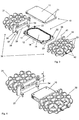
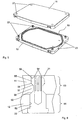
- FIGs. 3-12 illustrate several platelet concentrate preservation devices 1 that can be used for platelet concentrate preservation in accordance with the present invention.
- the device 1 includes a hermetically-sealed chamber 10 and a high-strength casing 30.
- the hermetically-sealed chamber 10 is designed to accommodate a bag with blood and/or a blood product (not shown in Fig. 3 ).
- the high-strength casing 30 is designed to protect the hermetically-sealed chamber 10, when located in the high-strength casing, against damage after a gas (e.g., gas or gas mixture) is fed under pressure into the hermetically-sealed chamber.
- a gas e.g., gas or gas mixture
- the hermetically-sealed chamber 10 allows the hermetically-sealed chamber 10 to be formed of a thin material (without special requirements to its strength), thus designing the hermetically-sealed chamber as a relatively inexpensive, single use component.
- the high-strength casing is designed to be a reusable component of device 1.
- the hermetically-sealed chamber 10 includes two parts 11 and 12.
- the parts are designed to be essentially flat; however, this is not required.
- Parts 11 and 12 are illustrated as having recesses 13 and 14, respectively, in their central areas. When parts 11 and 12 are joined together, these recesses form a cavity 15, into which a bag with blood product (not shown) is placed.
- the cavity of the hermetically-sealed chamber 10 can be generally shaped as essentially parallelepiped, wherein the legs of which are characterized by proportions close to those characterizing sides of the bag filled with the blood product; however, the cavity can have other shapes.
- the hermetically-sealed chamber 10 can include annular grooves 16 and 17 that are located along the perimeter of parts 11 and 12 and which groove are positioned on the side of recesses 13 and 14.
- grooves 16 and 17 form an annular channel, into which a sealing gasket 18 can be positioned.
- the sealing gasket can have a variety of shapes.
- the groove can also have a variety of shapes and sizes. As can be appreciated, only one of the parts can include a groove.
- the sealing gasket can be in the form of a ring made of flexible material (e.g., rubber, polymer material, silicon, etc.).
- parts 11 and 12 of the hermetically-sealed chamber 10 can be held together in the joined-together state by means of four connecting rods 22 installed on parts 12 on the side of recess 14.
- rods 22 can be designed to fit tightly into matched holes 21 made in parts 11.
- rods 22 and holes 21 can be made so that easy connection/disconnection and reliable holding in place of both parts 11 and 12 of hermetically-sealed chamber 10 in the joined-together state can be achieved.
- connecting rod 22 can optionally include two parts-cylindrically-shaped base part 51 that is press-fitted or otherwise fixed in opening 52 of part 12 of hermetically-sealed chamber 10 and locking part 53 in the form of a sleeve made of flexible material and cut along its axis.
- leaflets 54 e.g., four leaflets 54
- leaflets 54 can include projections 55 with two conical surfaces 56 and 57 on their free ends.
- the ring-shaped protrusion 58 with conical surfaces 59 and 60 can be made in the wall of opening 21.
- projections 55 of leaflets 54 slide with their conical surface 56 over conical surface 60 of protrusion 58 of opening 21, and are bent (due to the flexible properties of the material in the direction of axis) and slide further over protrusion 58.
- projections 55 of leaflets 54 slide with their conical surface 57 over conical surface 59 of protrusion 58 and thereafter leaflets 54 unbend and get engaged with their projection 55 with ring-shaped protrusion 58 of opening 21.
- Both parts 11 and 12 of hermetically-sealed chamber 10 plus connecting rods 22 can be made, for example, out of plastic using injection molding methods or another method with selection of suitable materials providing required rigidity of produced articles and flexible properties of locking part 53 of connecting rods 22. As can be appreciated, other or additional materials can be used to form hermetically-sealed chamber 10. As illustrated in Fig. 8 , at least one channel 23 and a cavity 15 is formed when parts 11 and 12 are joined together.
- high-strength casing 30 is formed of two parts 31 and 32 that are designed to be joined together.
- Each part 31 and 32 of high-strength casing 30 is embodied as a honeycomb structure having strengthening ribs 33 oriented in three orthogonal planes and each forming pocket 34 in the central area.
- the number and orientation of the strengthening ribs on parts 31 and 32 are non-limiting.
- parts 31 and/or 32 can be absent strengthening ribs and/or other structures can be included in and/or used on parts 31 and/or 32 to provide structural strength to one or both parts.
- Pocket 34 is designed to accommodate at least a portion of hermetically-sealed chamber 10 when parts 31 and 32 are in the joined-together state.
- the joining of the two pockets together forms a chamber cavity for chamber 10.
- the size and depth of pocket 34 is sufficient for the accommodation of at least a portion (e.g., 40-60%, 50%, etc.) of chamber 10 in each part 31 and 32 of high-strength casing 30.
- the height (“h") of pocket 34 is generally selected to ensure placement of chamber 10 in the pocket with a minimal gap between the inner surface of the pocket and the outer surface of chamber 10.
- Each part 31 and 32 of high-strength casing 30 can include a flange 35, 36, respectively, on the open side of pocket 34.
- Four twist locks 37 can be optionally positioned on flanges 35 of part 31.
- the twist locks when used, can include a fixing catch 38 that are secured on bar 39 in such a way that the catch 38 is rotatable.
- the fixing catch can have other configurations.
- Mating cuts 41 can be formed in flange 36 of part 32. After flange 35 of part 31 and flange 36 of part 32 are joined together, fixing catches 38 can be turned in the direction of pocket 34, after which they turn out to be engaged with the rear part of flange 36.
- both parts 31 and 32 of high-strength casing 30 can be reliably fixed in the joined-together state.
- other or additional connection arrangements can be used to releaseably connect together parts 31 and 32.
- Parts 31 and 32 of high-strength casing 30 can be made, for example, out of plastic (using injection molding method or another method for this purpose) with selection of suitable materials that provide required rigidity and strength of manufactured article and which can protects hermetically-sealed chamber 10 from damage after gas is pumped into it under pressure.
- a fitting 40 can be used to fluidly connect the inner space of part 31 and/or 32 (that forms a part of the chamber cavity that is intended for accommodating a portion of the hermetically-sealed chamber 10).
- the fitting can be installed on the end face of part 31 and/or 32 of high-strength casing 30.
- Fitting 40 is positioned in such a way that when hermetically-sealed chamber 10 is placed into pocket 34 of part 31 and/or 32, fitting 40 gets hermetically connected with the inlet channel 23 made in the end face of part 12 of hermetically sealed chamber 10.
- fitting 40 has a projecting part 43 on its inner side, and the projecting part 43 advances into recess 44 made in the end face of part 12 of hermetically-sealed chamber 10 and connects with inlet channel 23.
- Hermetic sealing of the connection can be provided by means of a sealing ring 45 installed in the annular groove made on the side surface of projecting part 43.
- other or additional arrangements can be used ensuring hermetic sealing of the joint between inlet channel made in the end face of part 12 of hermetically-sealed chamber 10 and fitting 40 that is installed in the end face of part 31 and/or 32 of high-strength casing 30.
- the seal between inlet channel 23 and fitting 40 can be formed prior to or when parts 31 and 32 are connected together.
- cavity 15 of chamber 10 can be designed to be fluidly connected to the outside of casing 30 via channel 23 and fitting 40; however, this is not required.
- a one-way valve (not shown) can optionally be installed in fitting 40, which, on the one hand, allows insertion of a gas into cavity 15 of hermetically-sealed chamber 10 and, on the other hand, can be used to prevent gas egress from cavity 15.
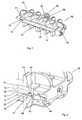
- Figs. 9-12 another non-limiting embodiment of the device for use with the method of the present invention is illustrated.
- the device illustrated in Figs. 9-12 is characterized by another design solution for components that provide feeding of a gas into cavity 15 of hermetically-sealed chamber 10, which is capable of feeding gas concurrently into a plurality of devices 10 that are arranged in a stack configuration.
- an end-to-end inlet channel 41 is made in part 31 and/or 32 of high-strength casing 30.
- the channel can be oriented generally perpendicular to the horizontal plane of the device; however, this is not required.
- a side channel 42 can be designed to abut the end-to-end channel 41, wherein the side channel 42 is designed to go in the direction of pocket 34 of part 21 and/or 32 so as to be able to engage with to inlet channel 23 of hermetically-sealed chamber 10, as previously described above, when chamber 10 is placed the of chamber cavity of the high-strength casing 30.
- End fitting 43 can be installed on one end of end-to-end inlet channel 41, and end fitting 44 can be installed on the other end of end-to-end inlet channel 41.
- End fittings 43 and 44 can optionally include a built-in one-way valve, not shown, through which gas can be fed into the device. Fitting 45 can be installed inside channel 42; however, this is not required.
- Fitting 45 can be designed to ensure airtight joining with hermetically-sealed chamber 10.
- This airtight joint is embodied in a similar way as the connection between fitting 40 and hermetically-sealed chamber 10 that is illustrated in Fig. 6 .
- an airtight cavity 15 of hermetically-sealed chamber 10 can be connected (through inlet channel 23 and fitting 45) with end-to-end inlet channel 41, into which gas can fed through fittings 43 or 44.
- Fittings 43 and 44 can optionally be made as quick-disconnect couplings, and fitting 43 of one device can be designed in such a way that airtight joining with end fitting 44 of another device can be achieved.
- Such a design provides the opportunity to arrange together several devices 1 in a stack configuration by fluidly connecting them together by means of fittings 43 and 44.
- end-to-end inlet channels 41 of devices 1 can be fluidly connected in series, thus forming a single inlet channel, through which gas can be fed concurrently into all the devices as illustrated in Fig. 12 .
- a drainage channel 46 with drainage valve 47 as illustrated in Fig. 10 can optionally be provided.
- the drainage channel can be included in part 31 and/or 32 of high-strength casing 30.
- the drainage channel 46 is designed to release gas from hermetically-sealed chamber 10 of the device.
- Drainage channel 46 can be designed to abut to end-to-end inlet channel 41 and goes outside part 31 and/or 32 of high-strength casing 30, thereby connecting end-to-end inlet channel 41 with the ambient atmosphere.
- Drainage valve 47 installed in drainage channel 46) enables the release gas from hermetically-sealed chamber 10 of the device, when necessary or desired.
- drainage valve 47 can be designed to be opened, thus letting the gas to pass from hermetically-sealed chamber 10 of the device into the ambient environment.
- other or additional designs can be used to controllably release gas from hermetically-sealed chamber 10.
- FIG. 11 One non-limiting example of a device 1 for preserving and storing blood products is illustrated in Fig. 11 .
- the device is shown in the assembled state and the following device components can be seen: the edge of hermetically-sealed chamber 10 installed into high-strength casing 30, parts 31 and 32 of which are interconnected by means of twist locks 37, fittings 43 and 44 intended for feeding gas into device and handle 48 of drainage valve intended for gas release.
- parts 31 and 32 of the high-strength casing can optionally have projections 50 and 51 oriented in the opposite directions relative to the horizontal plane of the device.
- Projections 50 and 51 when used, are intended for arranging several devices 1 in a stack as illustrated in Fig. 12 .
- Projections 50 can be shifted in the horizontal plane relative to the lying-opposite projections 51 in such a way that when arranging several devices in a stack, projections 50 of a device interact with projections 51 of the device located above the first one, and, accordingly, projections 51 interact with projections 50 of device located below the first one.
- Projection 51 is illustrated as having a recess portion that is designed to frictionally engage a portion of projection 50 when the devices are stacked together.
- projections 50 and 51 keep the stacked devices in place as shown in Fig. 12 .
- projections 50 and 51 can optionally be equipped with fasteners (e.g., screws, clamps, clips, etc.) not shown, which can be used to releasable secure together a plurality of stacked devices 1 to provide higher reliability of connecting together the stacked-together devices. This can be advantageous when a plurality of stacked devices are to be transported. As can be appreciated, other or additional configurations can be used to ensure in the releasably connecting together of several stacked devices.
- the above-described device can be used to preserve and store blood products that use a method wherein the preservation and storage takes place in a gas medium, including the situation where the method takes place under conditions of increased pressure.
- the device can be used when implementing blood product preservation methods described in US 2010/0009334 .
- the device can function as follows: A blood product, specifically a platelet concentrate, is placed in a bag made of gas-permeable material.
- the material used for bag manufacturing should be characterized by adequate gas permeability.
- the bag material is necessarily permeable for xenon.
- bags for platelet concentrate storage produced by CardianBCT (Lakewood, CO) and characterized by the above-indicated gas-permeability feature can be used for this purpose.
- the blood product to be preserved can be obtained through the use of well-known methods and appropriate available equipment.
- the hermetically-sealed bag with the blood product is placed in cavity 15 that is formed as a result of joining together parts 11 and 12 of hermetically-sealed chamber 10.
- An easy-to-use and reliable joining arrangement of parts 11 and 12 of hermetically-sealed chamber 10 can be used as above-described, wherein openings 21 are made in part 11 and connecting rods 22 are installed on part 12 of hermetically-sealed chamber 10.
- the bag with blood product is positioned in cavity 15 of hermetically-sealed chamber 10.
- the cavity 15 is connected with the outside only by means of inlet channel 23.
- parts 31 and 32 of high-strength casing 30 are inserted about hermetically-sealed chamber 10 to thereby position chamber 10 in the chamber cavity of the high-strength casing 30, which chamber cavity is formed by the joining together of pockets 34 of parts 31and32.
- the fixing catches 38 of twist locks 37 when used, are turned in advance in the opposite direction from pocket 34.
- Parts 31 and 32 are joined together when flanges 35 and 36 are fit tightly together and thereafter fixing catches 38 of twist locks 37 are turned, thus releasably connecting together parts 31 and 32.
- Fitting 42 is designed to connect hermetically with channel 23 of hermetically-sealed chamber 10, as a result of which cavity 15 of hermetically-sealed chamber 10 (after the latter has been placed into high-strength casing 30) turns out to be connected with the outside only through channel 23 and fitting 40.
- the one-way valve installed in fitting 40 provides unidirectional passage of gas into cavity 15 of hermetically-sealed chamber 10.
- Pockets 34 of parts 31 and 32 are also designed to be hermetically joined when parts 31 and 32 are connected together.
- the gas that is required in compliance with the used preservation method is then fed under pressure that is greater than atmospheric pressure at sea level into cavity 15 of hermetically-sealed chamber 10 through fitting 40.
- the gas is fed until the pressure in cavity 15 reaches a required value, after which gas feeding is terminated and the device is disconnected from the gas feeding system.
- the gas feeding system (not shown) may comprise a high-pressure bottle containing gas mixture of a required composition and tubing with a manometer and controlled valve made in such a way that it is possible to connect it hermetically with fitting 40.
- other or additional arrangements of the gas feeding system can be used.
- the device in the above-indicated state is kept during a certain period of time sufficient for the blood product to achieve the desired saturation with the appropriate component of gas pumped into the device.
- the device can be placed for storage at pre-specified temperatures (e.g., into a refrigerator).
- the gas system is a gas mixture comprising xenon
- the gas system is fed into the cavity of the chamber to at least partially saturate the platelet concentrate with xenon
- the bag is maintained in the cavity of the chamber in the presence of the gas system for at least 0.001 hours.
- a bag with platelet concentrate is first placed in a hermetically-sealed chamber 10, which is then placed in high-strength casing 30, after which a gas feeding system is connected through fitting 40.
- a gas mixture containing xenon e.g., at least 50-65% xenon
- the platelet concentrate (contained in the bags) is saturated with xenon, and creates conditions (namely, composition, pressure exerted by gas mixture and temperature) to provide preservation of the platelet concentrate in the bag.
- the device is stored in a refrigerator at a temperature approximately from 3°C to 6°C. It is desirable to place the device in a horizontal position. Taking the geometrical relationship of sides (indicated above) of the hermetically-sealed chamber and the device as a whole into account, a bag with blood product is stored in a position to ensure maximum area and minimum thickness of sediment formed in the course of platelet sedimentation during storage. However, if necessary, the blood product can be stored at a different orientation in the device.
- the device Prior to using the preserved blood product, the device is taken out from the refrigerator. If necessary, prior to unsealing the device, it can optionally be placed on a shaker for stirring the blood product contained in the bag. A sediment of formed elements of blood (produced in the course of storage) can then be transformed into the suspension as a result of stirring, while the increased pressure maintained during stirring inhibits or prevents generation of gas bubbles in the blood product.
- the gas is released from the hermetically-sealed chamber 10 (for instance, using a drainage valve for this purpose-as shown in Fig. 10 ), and after the pressure in cavity 15 is equalized with atmospheric pressure, the hermetically-sealed chamber 10 is opened and the bag with blood product is taken out from the chamber.
- the bag Prior to using the blood product, the bag can be kept for a certain time period until it warms up naturally (e.g., to room temperature) and the gas pressure inside the bag equalizes with atmospheric pressure.
- a platelet concentrate preservation method is set forth as follows: A platelet concentrate (not shown) is placed in a bag made of material that is at least permeable for xenon and oxygen.
- bags for platelet concentrate storage produced by CardianBCT (Lakewood, CO) characterized by the above-indicated gas-permeability feature could be used for this purpose.
- the bag containing the platelet concentrate is hermetically-sealed.
- the hermetically-sealed bag with platelet concentrate is placed in cavity 15 formed as a result of joining together parts 11 and 12 of chamber 10.
- the bag with the platelet concentrate (not shown in Figs. 3 and 4 ) is positioned in chamber 10 (e.g., the chamber is hermetically-sealed) and the inner space of cavity 15 is fluidly connected with channel 23.
- Parts 31 and 32 of high-strength casing 30 are inserted about chamber 10 and are connected together (e.g., with fixing catches 38 of twist locks 37 being turned in advance in the opposite direction from opening 34). Parts 31 and 32 are joined together to the point when flanges 35 and 36 fit tightly, after which fixing catches 38 of twist locks 37 are rotated, thus fixing parts 31 and 32 in the joined-together state.
- fitting 42 gets connected hermetically with channel 23 of hermetically-sealed chamber 10.
- cavity 15 of chamber 10 is fluidly connected to channel 23 and fitting 42 to enable gas to be inserted and/or removed from chamber 10 via channel 23 and filling 42.
- a valve e.g., one-way, etc.
- fitting 42 can be installed in fitting 42 to provide controlled (e.g., unidirectional, etc.) passage of gas into and/or out of cavity 15 of chamber 10.
- a gas mixture with xenon, xenon and oxygen e.g., 79-95% xenon and 5-21% oxygen
- xenon and one or more other gasses e.g., air, oxygen, nitrogen, etc.
- the gas mixture is fed until the pressure in cavity 15 reaches a desired value (e.g., 3.5-5 bars above atmospheric pressure, etc.), after which the device is disconnected from the gas source.
- the system for feeding the gas mixture may include a high-pressure bottle containing the gas mixture and tubing with a manometer and a controlled valve that is made in such a way that it is possible to connect it hermetically with fitting 42.
- a high-pressure bottle containing the gas mixture and tubing with a manometer and a controlled valve that is made in such a way that it is possible to connect it hermetically with fitting 42.
- other or additional arrangements for the system for feeding the gas mixture can be used.
- the step of feeding the gas mixture to chamber 10 can be carried out at a temperature of ambient environment and the gas mixture having a temperature of about 20°C to 24°C; however, other temperatures can be used.
- the platelet concentrate preservation device after being fed the gas mixture, is generally kept in the above-described state for a time period sufficient for partial or full saturation of the platelets with xenon.
- the platelet concentrate can optionally be additionally stirred (e.g., placing the device on a shaker [i.e., a standard shaker for platelet concentrate storage could be used for this purpose], etc.).
- the platelet concentrate preservation device after desired xenon saturation of the platelet concentrate is obtained, can be placed in a refrigerator, in which it is stored at a desired temperature (e.g., 3°C to 6°C).
- a desired temperature e.g. 3°C to 6°C.
- a standard refrigerator that is conventionally used for storing blood components can be used for this purpose. Due to the fact that the bags are made of a gaspermeable material, the platelet concentrate (contained in the bags) is partially or fully saturated with xenon, and creates conditions (namely, composition, pressure exerted by gas mixture and temperature) that provide for the preservation of platelet concentrate in the bag.
- the platelet concentrate preservation device can be stored in the refrigerator with the bag being in the generally horizontal position.
- the platelet concentrate preservation device Prior to using the preserved platelet concentrate, the platelet concentrate preservation device is taken out of the refrigerator and optionally placed on a shaker for stirring.
- the platelet pellet that has formed during the storage period is transformed (e.g., broken up, etc.) as a result of stirring, and the increased pressure maintained in the course of stirring inhibits or prevents generation of gas bubbles in the platelet concentrate.
- the valve in fitting 42 is opened and any excess pressure is released from cavity 15.
- chamber 10 is opened and the bag with platelet concentrate is removed from chamber 10.
- the bag Prior to using the platelet concentrate, the bag is held for a certain time period to enable the bag to warm up (e.g., naturally warm to room temperature) and to allow the gas pressure inside the bag to equalize with atmospheric or ambient pressure.
- a platelet concentrate preservation method is set forth as follows: A platelet concentrate (not shown) is placed in a bag made of material that is at least permeable for xenon and oxygen.
- bags for platelet concentrate storage produced by CardianBCT (Lakewood, CO) characterized by the above-indicated gas-permeability feature could be used for this purpose.
- the bag containing the platelet concentrate is hermetically sealed.
- the hermetically-sealed bag with platelet concentrate is placed in cavity 15 formed as a result of joining together parts 11 and 12 of chamber 10.
- the bag with the platelet concentrate (not shown in Figs. 3-12 ) is positioned in chamber 10 (e.g., the chamber is hermetically sealed) and the inner space of cavity 15 is fluidly connected with channel 23.
- Parts 31 and 32 of high-strength casing 30 are inserted about chamber 10 and are connected together (e.g., with fixing catches 38 of twist locks 37 being turned in advance in the opposite direction from opening 34). Parts 31 and 32 are joined together to the point when flanges 35 and 36 fit tightly, after which fixing catches 38 of twist locks 37 are rotated, thus fixing parts 31 and 32 in the joined-together state.
- fitting 42 gets connected hermetically with channel 23 of hermetically-sealed chamber 10.
- cavity 15 of chamber 10 is fluidly connected to channel 23 and fitting 42 to enable gas to be inserted and/or removed from chamber 10 via channel 23 and filling 42.
- a valve e.g., one-way, etc.
- fitting 42 can be installed in fitting 42 to provide controlled (e.g., unidirectional, etc.) passage of gas into and/or out of cavity 15 of chamber 10.
- a gas mixture with xenon and oxygen (e.g., 79-95% xenon and 5-21% oxygen) is pumped (e.g., under pressure) into cavity 15 of chamber 10 via channel 23 and fitting 42.
- the gas mixture is fed until the pressure in cavity 15 reaches a desired value (e.g., 3.5-5 bars. etc.), after which the device is disconnected from the gas source.
- the system for feeding the gas mixture may include a high-pressure bottle containing the gas mixture and tubing with a manometer and a controlled valve that is made in such a way that it is possible to connect it hermetically with fitting 42.
- other or additional arrangements for the system for feeding the gas mixture can be used.
- the step of feeding the gas mixture to chamber 10 can be carried out at a temperature of ambient environment and the gas mixture having a temperature of about 20°C to 24°C; however, other temperatures can be used.
- the platelet concentrate preservation device after being fed the gas mixture, is generally kept in the above-described state for a time period sufficient for partial or full saturation of the platelets with xenon.
- the platelet concentrate can optionally be additionally stirred (e.g., placing the device on a shaker [i.e., a standard shaker for platelet concentrate storage could be used for this purpose], etc.).
- the platelet concentrate preservation device after desired xenon saturation of the platelet concentrate is obtained, can be placed in a refrigerator, in which it is stored at a desired temperature (e.g., 3°C to 6°C).
- a desired temperature e.g. 3°C to 6°C.
- a standard refrigerator that is conventionally used for storing blood components can be used for this purpose. Due to the fact that the bags are made of a gas-permeable material, the platelet concentrate (contained in the bags) is partially or fully saturated with xenon, and creates conditions (namely, composition, pressure exerted by gas mixture and temperature) that provide for the preservation of platelet concentrate in the bag.
- the platelet concentrate preservation device can be stored in the refrigerator with the bag being in the generally horizontal position.
- the platelet concentrate preservation device Prior to using the preserved platelet concentrate, the platelet concentrate preservation device is taken out of the refrigerator and optionally placed on a shaker for stirring.
- the platelet pellet that has formed during the storage period is transformed (e.g., broken up, etc.) as a result of stirring, and the increased pressure maintained in the course of stirring inhibits or prevents generation of gas bubbles in the platelet concentrate.
- the valve in fitting 42 is opened and any excess pressure is released from cavity 15.
- chamber 10 is opened and the bag with platelet concentrate is removed from chamber 10.
- the bag Prior to using the platelet concentrate, the bag is held for a certain time period to enable the bag to warm up (e.g., naturally warm to room temperature) and to allow the gas pressure inside the bag to equalize with atmospheric or ambient pressure.
- a set of experiments was staged to verify the implementation of a platelet concentrate preservation method according to the present disclosure and to confirm the obtainment of the above-indicated results as compared to the known methods.
- the platelet concentrate was placed into plastic bags intended for platelet concentrate storage.
- the bag with platelet concentrate was placed in the above-described device (see Figs. 3-12 ), into which a gas mixture containing 87% xenon and 13% oxygen was pumped under pressure into cavity 15.
- the platelet concentrate preservation device After keeping the platelet concentrate preservation device a period of 3.5 hours at room temperature (e.g., 22°C), the platelet concentrate preservation device was placed in a refrigerator (temperature of approximately 4°C). The platelet concentrate was stored for a period of 14 days.
- the platelet concentrate was obtained by the standard method used in clinics - by means of an aphaeresis apparatus, Trima Accel®, with the use of standard bags having gas-permeable walls for platelet concentrate storage. These bags were available from CardianBCT (Lakewood, CO). The parameters for obtaining the platelet concentrate were as follows:
- the experimental bags were stored in a generally horizontal position. Upon completion of storage, the platelet concentrate preservation device with the experimental bags was taken out from the refrigerator and placed on an orbital shaker. Stirring was conducted at room temperature (approximately 22°C) for a time period of about ten (10) minutes with a rotation frequency of 150 min -1 (rpm). After the shaking step, the pressure of the gas mixture was released from cavity 15, and the bag was taken out of the platelet concentrate preservation device and kept for three (3) hours at room temperature (without stirring) to allow the bag to naturally warm up and to allow the pressure in the bag to equalize with the ambient atmosphere at sea level (e.g., 1 atm.).
- control (reference) bags were stored in a vertical position. Upon completion of storage, the storage device that included the control (reference) bag was taken out from the refrigerator and the pressure of the gas mixture was released from the storage device. The extracted bag was then carefully crumpled to eliminate the platelet pellet. Thereafter, the bag was taken out from the storage device and kept for three (3) hours at room temperature (without stirring) to allow the bag to naturally warm up and to allow the pressure in the bag to equalize with the ambient atmosphere at sea level (e.g., 1 atm.).
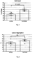
- Cell Count - a parameter indicating the degree of platelet population preservation after storage. This parameter is calculated as a percentage from the number of cells in the beginning of experiment - i.e., prior to starting the platelet concentrate preservation. A high percentage of preserved cells indicates that a small number of flakes and micro-aggregates were formed during storage as a result of platelets sticking together. The cells were counted before and after storage with the use of Guava EasyCyte 5HT Flow Cytometer - which can directly determine cell concentration in a sample being analyzed.
- Aggregation - a functional indicator of cell activity. This measurement indicates the ability of stored platelets to produce clots in blood vessels with damaged walls after transfusion.
- the platelets' level of aggregation was determined by means of a SOLAR AP-2110 (Belarus) aggregometer by turbidimetric method ( Jarvis GE., "Platelet aggregation: turbidimetric measurements” Methods Mol Biol 272:65-76 (2004 ) with the use of an ADP and an epinephrine as inducing factors for the mixture. This method is used to measure (in percentage terms) the variation in platelet suspension transparency after the addition of an aggregation agent.
- Fig. 1 It can be seen from Fig. 1 that the platelet preservation method in accordance with the present disclosure does not impair the functional properties of platelets.
- the method in accordance with the present disclosure enables one to store platelet concentrate more efficiently, prevent the sticking of platelets together, and not impair the functional properties of the platelets.
- the aphaeresis platelet concentrate obtained through the use of standard methods
- standard plastic bags intended for platelet concentrate storage could be used with the method.
- the absence of dense deposit in the end of storage period allows for improved quality and safety of platelet concentrate that is transfused to patients.
Landscapes
- Health & Medical Sciences (AREA)
- Life Sciences & Earth Sciences (AREA)
- General Health & Medical Sciences (AREA)
- Engineering & Computer Science (AREA)
- Animal Behavior & Ethology (AREA)
- Public Health (AREA)
- Veterinary Medicine (AREA)
- Heart & Thoracic Surgery (AREA)
- Zoology (AREA)
- Wood Science & Technology (AREA)
- Dentistry (AREA)
- Environmental Sciences (AREA)
- Hematology (AREA)
- Pharmacology & Pharmacy (AREA)
- Biomedical Technology (AREA)
- Anesthesiology (AREA)
- Vascular Medicine (AREA)
- Medical Preparation Storing Or Oral Administration Devices (AREA)
- Packages (AREA)
Claims (13)
- Ein Verfahren zur Lagerung von Thrombozytenkonzentrat, das Folgendes beinhaltet:a. Platzieren eines Thrombozytenkonzentrats in einen hermetisch versiegelten Beutel, wobei der Beutel aus einem für ein Gassystem durchlässigen Material gebildet ist, wobei das genannte Gassystem ein Xenon beinhaltendes Gasgemisch ist;b. Platzieren des Beutels in einem Hohlraum (15) einer Kammer (10), wobei die genannte Kammer erste und zweite Kammerteile (11, 12) umfasst, die den genannten Hohlraum bilden, wenn sie lösbar miteinander verbunden sind;c. Platzieren der genannten Kammer, die den genannten Beutel umfasst, in einen Kammerhohlraum eines hochfesten Gehäuses (30), wobei das genannte hochfeste Gehäuse erste und zweite Gehäuseteile (31, 32) umfasst, die den genannten Kammerhohlraum bilden, wenn sie lösbar miteinander verbunden sind;d. Einleiten des genannten Gassystems in den genannten Hohlraum der genannten Kammer, um das genannte Thrombozytenkonzentrat mindestens teilweise mit Xenon zu sättigen, wobei das genannte Gassystem unter einem Druck, der höher ist als der Luftdruck auf Meeresspiegel, in die genannte versiegelte Kammer eingeleitet wird; unde. Halten des genannten Beutels des genannten Thrombozytenkonzentrats in dem genannten Hohlraum der genannten Kammer in genannter Gegenwart des genannten Gassystems für mindestens 0,001 Stunden.
- Verfahren nach Anspruch 1, das ferner den folgenden Schritt umfasst:f. nachdem das genannte Thrombozytenkonzentrat eine gewünschte Sättigung des genannten mindestens einen Gases in dem genannten Gassystem erreicht hat, Kühlen des genannten Beutels, der das genannte Blut, Blutkomponenten oder Kombinationen davon enthält, in einem Kühlsystem bis zu einer Lagertemperatur, wobei die genannte Lagertemperatur geringer als etwa 15 °C und höher als ein Gefrierpunkt des genannten Bluts, der Blutkomponenten oder Kombinationen davon ist und wobei die genannte Temperatur bevorzugt 0,01 °C bis 15 °C beträgt.
- Verfahren nach Anspruch 2, das ferner die folgenden Schritte umfasst:g. Ablassen des genannten Drucks in der genannten Kammer;h. Entfernen der genannten Kammer von dem genannten Kammerhohlraum;i. Entfernen des genannten Beutels aus dem Hohlraum der genannten Kammer; undj. Erwärmen des genannten Beutels auf mehr als die genannte Lagertemperatur.
- Verfahren nach einem der Ansprüche 1-3, das ferner den Schritt des Schüttelns, Rührens oder einer Kombination davon des genannten Thrombozytenkonzentrats in dem genannten Beutel vor einer Transfusion für einen Patienten umfasst.
- Verfahren nach einem der Ansprüche 1-4, das ferner den Schritt des Ausrichtens des genannten Beutels in einer allgemein horizontalen Position für einen gewünschten Zeitraum bei der genannten Lagertemperatur umfasst.
- Verfahren nach einem der Ansprüche 1-5, wobei der genannte Hohlraum der genannten Kammer ein hermetisch versiegelbarer Hohlraum ist.
- Verfahren nach einem der Ansprüche 1-6, wobei das genannte Gassystem einen Xenongehalt aufweist, der höher ist als ein in der Luft auf Meeresspiegel natürlich vorkommender Xenongehalt, und wobei das genannte Gasgemisch bevorzugt zu etwa 50 Volumen-% bis 99,9 Volumen-% Xenon und zu etwa 0 Volumen-% bis 50 Volumen-% Sauerstoff umfasst.
- Verfahren nach einem der Ansprüche 1-7, wobei das genannte Gasgemisch der genannten Kammer unter einem Druck zugeführt wird, der um mindestens 1 bar über dem Luftdruck auf Meeresspiegel liegt.
- Verfahren nach einem der Ansprüche 1-8, wobei das genannte Gasgemisch in die genannte Kammer eingeleitet wird, während das genannte Thrombozytenkonzentrat eine Temperatur von etwa 18 °C bis 35 °C aufweist.
- Verfahren nach einem der Ansprüche 1-9, wobei das genannte Gasgemisch der genannten Kammer zugeführt wird, bis das genannte Thrombozytenkonzentrat zu mindestens 50% mit Xenongas gesättigt ist.
- Verfahren nach einem der Ansprüche 1-10, wobei der genannte Schritt des Haltens des genannten Beutels des genannten Thrombozytenkonzentrats in der genannten Kammer in der genannten Gegenwart des genannten Gasgemischs für 0,001-10 Stunden erfolgt.
- Verfahren nach einem der Ansprüche 1-11, wobei die genannte Kammer einen Einlasskanal umfasst, der eine Fluidverbindung von dem genannten Hohlraum zu einem Gehäusekanal in dem genannten hochfesten Gehäuse herstellt, um zu erlauben, dass eine Gasquelle, die das genannte Gassystem umfasst, mit dem genannten hochfesten Gehäuse verbunden wird, sodass das genannte Gassystem durch das genannte hochfeste Gehäuse und in den genannten Hohlraum der genannten Kammer hinein fließen kann, wobei
der genannte Einlasskanal optional hermetisch gegen den genannten Gehäusekanal versiegelt ist, wenn die genannte Kammer in dem genannten Kammerhohlraum positioniert ist und die genannten ersten und zweiten Teile des genannten hochfesten Gehäuses miteinander verbunden sind, und wobei
das genannte Material, das zum Bilden des genannten hochfesten Gehäuses verwendet wird, optional mindestens etwa 2 mal stärker ist, mindestens 2 mal starrer ist oder Kombinationen davon als ein zum Bilden der genannten Kammer verwendetes Material. - Verfahren nach einem der Ansprüche 1-12, wobei die genannte Kammer mindestens etwa 70% eines Volumens des genannten Kammerhohlraums füllt, wenn die genannte Kammer in dem genannten Kammerhohlraum positioniert ist, und bevorzugt eine Außenfläche der genannten Kammer um einen maximalen Abstand von etwa 0,00254 cm bis 1,27 cm (0,001-0,5 Zoll) von einer Innenfläche des genannten Kammerhohlraums beabstandet ist, wenn die genannte Kammer in dem genannten Kammerhohlraum positioniert ist.
Applications Claiming Priority (2)
| Application Number | Priority Date | Filing Date | Title |
|---|---|---|---|
| US201261739327P | 2012-12-19 | 2012-12-19 | |
| PCT/US2013/074251 WO2014099515A1 (en) | 2012-12-19 | 2013-12-11 | Platelet concentrate preservation method |
Publications (3)
| Publication Number | Publication Date |
|---|---|
| EP2934111A1 EP2934111A1 (de) | 2015-10-28 |
| EP2934111A4 EP2934111A4 (de) | 2016-12-28 |
| EP2934111B1 true EP2934111B1 (de) | 2020-03-25 |
Family
ID=50979039
Family Applications (1)
| Application Number | Title | Priority Date | Filing Date |
|---|---|---|---|
| EP13865922.2A Active EP2934111B1 (de) | 2012-12-19 | 2013-12-11 | Konservierungsverfahren für thrombozytenkonzentrat |
Country Status (7)
| Country | Link |
|---|---|
| US (1) | US9686978B2 (de) |
| EP (1) | EP2934111B1 (de) |
| CN (1) | CN105050390B (de) |
| CA (1) | CA2894161C (de) |
| ES (1) | ES2784202T3 (de) |
| RU (2) | RU2017144440A (de) |
| WO (1) | WO2014099515A1 (de) |
Families Citing this family (11)
| Publication number | Priority date | Publication date | Assignee | Title |
|---|---|---|---|---|
| US10138025B2 (en) | 2013-04-05 | 2018-11-27 | Terumo Kabushiki Kaisha | Medical bag handling system and medical bag holding cassette |
| JP6655603B2 (ja) * | 2015-03-24 | 2020-02-26 | テルモ株式会社 | 凍結バッグ収納容器 |
| KR102672435B1 (ko) * | 2017-03-03 | 2024-06-07 | 리치 테크놀로지스 홀딩 컴퍼니 엘엘씨 | 압력 하의 가스 매질에서 혈액 제제 및 세포 배양물을 보존하기 위한 장치 |
| CN107047538B (zh) * | 2017-03-16 | 2021-04-13 | 苏州大学 | 蛋白激酶a激活剂在血小板保存中的应用及血小板保存方法 |
| KR102732698B1 (ko) * | 2018-04-11 | 2024-11-20 | 바이오라이프 솔루션 인코포레이티드 | 냉동보관 백 (cryostorage bag) 보호를 위한 시스템들 및 방법들 |
| JP7610409B2 (ja) * | 2018-04-20 | 2025-01-08 | バイオライフ・ソリューションズ・インコーポレイテッド | 複合機能極低温保存容器 |
| US20200196593A1 (en) * | 2018-12-21 | 2020-06-25 | Fenwal, Inc. | Methods and Systems for Platelet Cryopreservation |
| CN110732271B (zh) * | 2019-11-26 | 2020-07-21 | 王超 | 一种血小板振荡贮存箱 |
| CN113712023B (zh) * | 2021-04-02 | 2023-07-04 | 苏州大学 | 一种血小板的保存方法 |
| US11629821B1 (en) | 2022-01-19 | 2023-04-18 | Praxair Technology, Inc. | Gas dosing apparatus with directional control valve |
| US12410960B2 (en) * | 2023-05-15 | 2025-09-09 | MH Product Development, LLC | Device and methods for freezing liquids into a flat form |
Family Cites Families (12)
| Publication number | Priority date | Publication date | Assignee | Title |
|---|---|---|---|---|
| US6413713B1 (en) * | 1998-10-30 | 2002-07-02 | Hyperbaric Systems | Method for preserving blood platelets |
| CN1901795B (zh) * | 2003-10-22 | 2014-03-26 | 弗雷德哈钦森癌症研究中心 | 用于在细胞,组织,器官,和有机体中诱导停滞的方法,组合物和装置 |
| CA2605631A1 (en) | 2005-04-20 | 2006-10-26 | Fred Hutchinson Cancer Research Center | Methods, compositions and articles of manufacture for enhancing survivability of cells, tissues, organs, and organisms |
| RU2326532C1 (ru) * | 2006-08-29 | 2008-06-20 | Федеральное государственное учреждение "Кировский научно-исследовательский институт гематологии и переливания крови Федерального агентства по высокотехнологичной медицинской помощи" (ФГУ "КНИИГ и ПК Росмедтехнологий") | Способ криоконсервирования тромбоцитов |
| EP2008669A1 (de) * | 2007-06-22 | 2008-12-31 | Maco Pharma S.A. | Bestrahlungsvorrichtung zur Deaktivierung von Krankheitserregern und/oder Leukozyten in einer biologischen Flüssigkeit und entsprechendes Verfahren |
| US8158339B2 (en) | 2008-07-07 | 2012-04-17 | Rich Products Corporation | Method of preserving a platelet concentrate under elevated xenon concentration and pressure with refrigeration |
| WO2010088364A2 (en) * | 2009-01-30 | 2010-08-05 | L'air Liquide Societe Anonyme Pour L'etude Et L'exploitation Des Procedes Georges Claude | Process for preserving biological materials for extended periods of time |
| WO2010132627A2 (en) * | 2009-05-13 | 2010-11-18 | Haemonetics Corporation | System and method for active cooling of stored blood products |
| CA2824948C (en) | 2011-02-07 | 2020-06-02 | Rich Products Corporation | Method for preserving cells and cell cultures |
| US9743660B2 (en) | 2011-06-22 | 2017-08-29 | Rich Technologies Holding Company, Llc | System, method, and device for preserving blood or its components in gas medium under pressure |
| CN104114688B (zh) * | 2011-09-26 | 2016-08-31 | 先进保存技术股份有限公司 | 活组织保存的方法 |
| WO2014099513A1 (en) * | 2012-12-19 | 2014-06-26 | Advanced Preservations Technologies, Llc | Device for preserving blood products in a gas medium under pressure |
-
2013
- 2013-12-11 EP EP13865922.2A patent/EP2934111B1/de active Active
- 2013-12-11 RU RU2017144440A patent/RU2017144440A/ru not_active Application Discontinuation
- 2013-12-11 US US14/648,804 patent/US9686978B2/en not_active Expired - Fee Related
- 2013-12-11 CA CA2894161A patent/CA2894161C/en active Active
- 2013-12-11 RU RU2015129088A patent/RU2661371C2/ru active
- 2013-12-11 ES ES13865922T patent/ES2784202T3/es active Active
- 2013-12-11 WO PCT/US2013/074251 patent/WO2014099515A1/en not_active Ceased
- 2013-12-11 CN CN201380073195.6A patent/CN105050390B/zh not_active Expired - Fee Related
Non-Patent Citations (1)
| Title |
|---|
| None * |
Also Published As
| Publication number | Publication date |
|---|---|
| RU2015129088A (ru) | 2017-01-26 |
| CA2894161A1 (en) | 2014-06-26 |
| CN105050390A (zh) | 2015-11-11 |
| WO2014099515A1 (en) | 2014-06-26 |
| CN105050390B (zh) | 2017-08-11 |
| US20150305324A1 (en) | 2015-10-29 |
| RU2017144440A (ru) | 2019-02-15 |
| CA2894161C (en) | 2022-08-02 |
| EP2934111A1 (de) | 2015-10-28 |
| RU2661371C2 (ru) | 2018-07-16 |
| US9686978B2 (en) | 2017-06-27 |
| ES2784202T3 (es) | 2020-09-23 |
| EP2934111A4 (de) | 2016-12-28 |
Similar Documents
| Publication | Publication Date | Title |
|---|---|---|
| EP2934111B1 (de) | Konservierungsverfahren für thrombozytenkonzentrat | |
| US11279510B2 (en) | System and method for freeze-drying and packaging | |
| AU2022203076B2 (en) | Oxygen reduction disposable kits, devices and methods of use thereof | |
| US10806665B2 (en) | System and method for freeze-drying and packaging | |
| US11833108B2 (en) | Terminal sterilization filtration closed lyophilization in a container | |
| US20180021218A1 (en) | Bag assembly sterilizable by gamma irradiation | |
| AU2018228495B2 (en) | Device for preserving blood products and cellular cultures in a gas medium under pressure | |
| ES2568247T3 (es) | Kit para la conservación de un producto biológico que comprende una bolsa tridimensional y una envoltura tridimensional adaptada | |
| TWI598090B (zh) | 血小板濃縮物保存方法 |
Legal Events
| Date | Code | Title | Description |
|---|---|---|---|
| PUAI | Public reference made under article 153(3) epc to a published international application that has entered the european phase |
Free format text: ORIGINAL CODE: 0009012 |
|
| 17P | Request for examination filed |
Effective date: 20150608 |
|
| AK | Designated contracting states |
Kind code of ref document: A1 Designated state(s): AL AT BE BG CH CY CZ DE DK EE ES FI FR GB GR HR HU IE IS IT LI LT LU LV MC MK MT NL NO PL PT RO RS SE SI SK SM TR |
|
| AX | Request for extension of the european patent |
Extension state: BA ME |
|
| DAX | Request for extension of the european patent (deleted) | ||
| RIC1 | Information provided on ipc code assigned before grant |
Ipc: A01N 1/02 20060101AFI20160729BHEP Ipc: A61J 1/16 20060101ALI20160729BHEP |
|
| A4 | Supplementary search report drawn up and despatched |
Effective date: 20161128 |
|
| RIC1 | Information provided on ipc code assigned before grant |
Ipc: A61J 1/16 20060101ALI20161122BHEP Ipc: A01N 1/02 20060101AFI20161122BHEP |
|
| RAP1 | Party data changed (applicant data changed or rights of an application transferred) |
Owner name: RICH TECHNOLOGIES HOLDING COMPANY, LLC |
|
| GRAP | Despatch of communication of intention to grant a patent |
Free format text: ORIGINAL CODE: EPIDOSNIGR1 |
|
| STAA | Information on the status of an ep patent application or granted ep patent |
Free format text: STATUS: GRANT OF PATENT IS INTENDED |
|
| RIC1 | Information provided on ipc code assigned before grant |
Ipc: A61J 1/16 20060101ALI20190926BHEP Ipc: A01N 1/02 20060101AFI20190926BHEP Ipc: A61M 1/02 20060101ALI20190926BHEP |
|
| INTG | Intention to grant announced |
Effective date: 20191016 |
|
| GRAS | Grant fee paid |
Free format text: ORIGINAL CODE: EPIDOSNIGR3 |
|
| GRAA | (expected) grant |
Free format text: ORIGINAL CODE: 0009210 |
|
| STAA | Information on the status of an ep patent application or granted ep patent |
Free format text: STATUS: THE PATENT HAS BEEN GRANTED |
|
| AK | Designated contracting states |
Kind code of ref document: B1 Designated state(s): AL AT BE BG CH CY CZ DE DK EE ES FI FR GB GR HR HU IE IS IT LI LT LU LV MC MK MT NL NO PL PT RO RS SE SI SK SM TR |
|
| REG | Reference to a national code |
Ref country code: GB Ref legal event code: FG4D |
|
| REG | Reference to a national code |
Ref country code: AT Ref legal event code: REF Ref document number: 1247464 Country of ref document: AT Kind code of ref document: T Effective date: 20200415 Ref country code: IE Ref legal event code: FG4D |
|
| REG | Reference to a national code |
Ref country code: DE Ref legal event code: R096 Ref document number: 602013067294 Country of ref document: DE |
|
| REG | Reference to a national code |
Ref country code: NL Ref legal event code: FP |
|
| REG | Reference to a national code |
Ref country code: NO Ref legal event code: T2 Effective date: 20200325 |
|
| PG25 | Lapsed in a contracting state [announced via postgrant information from national office to epo] |
Ref country code: RS Free format text: LAPSE BECAUSE OF FAILURE TO SUBMIT A TRANSLATION OF THE DESCRIPTION OR TO PAY THE FEE WITHIN THE PRESCRIBED TIME-LIMIT Effective date: 20200325 Ref country code: FI Free format text: LAPSE BECAUSE OF FAILURE TO SUBMIT A TRANSLATION OF THE DESCRIPTION OR TO PAY THE FEE WITHIN THE PRESCRIBED TIME-LIMIT Effective date: 20200325 |
|
| PG25 | Lapsed in a contracting state [announced via postgrant information from national office to epo] |
Ref country code: HR Free format text: LAPSE BECAUSE OF FAILURE TO SUBMIT A TRANSLATION OF THE DESCRIPTION OR TO PAY THE FEE WITHIN THE PRESCRIBED TIME-LIMIT Effective date: 20200325 Ref country code: SE Free format text: LAPSE BECAUSE OF FAILURE TO SUBMIT A TRANSLATION OF THE DESCRIPTION OR TO PAY THE FEE WITHIN THE PRESCRIBED TIME-LIMIT Effective date: 20200325 Ref country code: LV Free format text: LAPSE BECAUSE OF FAILURE TO SUBMIT A TRANSLATION OF THE DESCRIPTION OR TO PAY THE FEE WITHIN THE PRESCRIBED TIME-LIMIT Effective date: 20200325 Ref country code: BG Free format text: LAPSE BECAUSE OF FAILURE TO SUBMIT A TRANSLATION OF THE DESCRIPTION OR TO PAY THE FEE WITHIN THE PRESCRIBED TIME-LIMIT Effective date: 20200625 Ref country code: GR Free format text: LAPSE BECAUSE OF FAILURE TO SUBMIT A TRANSLATION OF THE DESCRIPTION OR TO PAY THE FEE WITHIN THE PRESCRIBED TIME-LIMIT Effective date: 20200626 |
|
| REG | Reference to a national code |
Ref country code: LT Ref legal event code: MG4D |
|
| REG | Reference to a national code |
Ref country code: ES Ref legal event code: FG2A Ref document number: 2784202 Country of ref document: ES Kind code of ref document: T3 Effective date: 20200923 |
|
| PG25 | Lapsed in a contracting state [announced via postgrant information from national office to epo] |
Ref country code: RO Free format text: LAPSE BECAUSE OF FAILURE TO SUBMIT A TRANSLATION OF THE DESCRIPTION OR TO PAY THE FEE WITHIN THE PRESCRIBED TIME-LIMIT Effective date: 20200325 Ref country code: CZ Free format text: LAPSE BECAUSE OF FAILURE TO SUBMIT A TRANSLATION OF THE DESCRIPTION OR TO PAY THE FEE WITHIN THE PRESCRIBED TIME-LIMIT Effective date: 20200325 Ref country code: PT Free format text: LAPSE BECAUSE OF FAILURE TO SUBMIT A TRANSLATION OF THE DESCRIPTION OR TO PAY THE FEE WITHIN THE PRESCRIBED TIME-LIMIT Effective date: 20200818 Ref country code: SM Free format text: LAPSE BECAUSE OF FAILURE TO SUBMIT A TRANSLATION OF THE DESCRIPTION OR TO PAY THE FEE WITHIN THE PRESCRIBED TIME-LIMIT Effective date: 20200325 Ref country code: LT Free format text: LAPSE BECAUSE OF FAILURE TO SUBMIT A TRANSLATION OF THE DESCRIPTION OR TO PAY THE FEE WITHIN THE PRESCRIBED TIME-LIMIT Effective date: 20200325 Ref country code: EE Free format text: LAPSE BECAUSE OF FAILURE TO SUBMIT A TRANSLATION OF THE DESCRIPTION OR TO PAY THE FEE WITHIN THE PRESCRIBED TIME-LIMIT Effective date: 20200325 Ref country code: IS Free format text: LAPSE BECAUSE OF FAILURE TO SUBMIT A TRANSLATION OF THE DESCRIPTION OR TO PAY THE FEE WITHIN THE PRESCRIBED TIME-LIMIT Effective date: 20200725 Ref country code: SK Free format text: LAPSE BECAUSE OF FAILURE TO SUBMIT A TRANSLATION OF THE DESCRIPTION OR TO PAY THE FEE WITHIN THE PRESCRIBED TIME-LIMIT Effective date: 20200325 |
|
| REG | Reference to a national code |
Ref country code: AT Ref legal event code: MK05 Ref document number: 1247464 Country of ref document: AT Kind code of ref document: T Effective date: 20200325 |
|
| REG | Reference to a national code |
Ref country code: DE Ref legal event code: R097 Ref document number: 602013067294 Country of ref document: DE |
|
| PG25 | Lapsed in a contracting state [announced via postgrant information from national office to epo] |
Ref country code: DK Free format text: LAPSE BECAUSE OF FAILURE TO SUBMIT A TRANSLATION OF THE DESCRIPTION OR TO PAY THE FEE WITHIN THE PRESCRIBED TIME-LIMIT Effective date: 20200325 Ref country code: AT Free format text: LAPSE BECAUSE OF FAILURE TO SUBMIT A TRANSLATION OF THE DESCRIPTION OR TO PAY THE FEE WITHIN THE PRESCRIBED TIME-LIMIT Effective date: 20200325 |
|
| PLBE | No opposition filed within time limit |
Free format text: ORIGINAL CODE: 0009261 |
|
| STAA | Information on the status of an ep patent application or granted ep patent |
Free format text: STATUS: NO OPPOSITION FILED WITHIN TIME LIMIT |
|
| PG25 | Lapsed in a contracting state [announced via postgrant information from national office to epo] |
Ref country code: PL Free format text: LAPSE BECAUSE OF FAILURE TO SUBMIT A TRANSLATION OF THE DESCRIPTION OR TO PAY THE FEE WITHIN THE PRESCRIBED TIME-LIMIT Effective date: 20200325 |
|
| 26N | No opposition filed |
Effective date: 20210112 |
|
| PG25 | Lapsed in a contracting state [announced via postgrant information from national office to epo] |
Ref country code: SI Free format text: LAPSE BECAUSE OF FAILURE TO SUBMIT A TRANSLATION OF THE DESCRIPTION OR TO PAY THE FEE WITHIN THE PRESCRIBED TIME-LIMIT Effective date: 20200325 |
|
| REG | Reference to a national code |
Ref country code: CH Ref legal event code: PL |
|
| PG25 | Lapsed in a contracting state [announced via postgrant information from national office to epo] |
Ref country code: MC Free format text: LAPSE BECAUSE OF FAILURE TO SUBMIT A TRANSLATION OF THE DESCRIPTION OR TO PAY THE FEE WITHIN THE PRESCRIBED TIME-LIMIT Effective date: 20200325 |
|
| REG | Reference to a national code |
Ref country code: BE Ref legal event code: MM Effective date: 20201231 |
|
| PG25 | Lapsed in a contracting state [announced via postgrant information from national office to epo] |
Ref country code: LU Free format text: LAPSE BECAUSE OF NON-PAYMENT OF DUE FEES Effective date: 20201211 Ref country code: IE Free format text: LAPSE BECAUSE OF NON-PAYMENT OF DUE FEES Effective date: 20201211 |
|
| PG25 | Lapsed in a contracting state [announced via postgrant information from national office to epo] |
Ref country code: CH Free format text: LAPSE BECAUSE OF NON-PAYMENT OF DUE FEES Effective date: 20201231 Ref country code: LI Free format text: LAPSE BECAUSE OF NON-PAYMENT OF DUE FEES Effective date: 20201231 |
|
| PG25 | Lapsed in a contracting state [announced via postgrant information from national office to epo] |
Ref country code: TR Free format text: LAPSE BECAUSE OF FAILURE TO SUBMIT A TRANSLATION OF THE DESCRIPTION OR TO PAY THE FEE WITHIN THE PRESCRIBED TIME-LIMIT Effective date: 20200325 Ref country code: MT Free format text: LAPSE BECAUSE OF FAILURE TO SUBMIT A TRANSLATION OF THE DESCRIPTION OR TO PAY THE FEE WITHIN THE PRESCRIBED TIME-LIMIT Effective date: 20200325 Ref country code: CY Free format text: LAPSE BECAUSE OF FAILURE TO SUBMIT A TRANSLATION OF THE DESCRIPTION OR TO PAY THE FEE WITHIN THE PRESCRIBED TIME-LIMIT Effective date: 20200325 |
|
| PG25 | Lapsed in a contracting state [announced via postgrant information from national office to epo] |
Ref country code: MK Free format text: LAPSE BECAUSE OF FAILURE TO SUBMIT A TRANSLATION OF THE DESCRIPTION OR TO PAY THE FEE WITHIN THE PRESCRIBED TIME-LIMIT Effective date: 20200325 Ref country code: AL Free format text: LAPSE BECAUSE OF FAILURE TO SUBMIT A TRANSLATION OF THE DESCRIPTION OR TO PAY THE FEE WITHIN THE PRESCRIBED TIME-LIMIT Effective date: 20200325 |
|
| PG25 | Lapsed in a contracting state [announced via postgrant information from national office to epo] |
Ref country code: BE Free format text: LAPSE BECAUSE OF NON-PAYMENT OF DUE FEES Effective date: 20201231 |
|
| PGFP | Annual fee paid to national office [announced via postgrant information from national office to epo] |
Ref country code: NO Payment date: 20221123 Year of fee payment: 10 Ref country code: NL Payment date: 20221123 Year of fee payment: 10 Ref country code: IT Payment date: 20221122 Year of fee payment: 10 Ref country code: GB Payment date: 20221116 Year of fee payment: 10 Ref country code: FR Payment date: 20221122 Year of fee payment: 10 Ref country code: DE Payment date: 20221122 Year of fee payment: 10 |
|
| PGFP | Annual fee paid to national office [announced via postgrant information from national office to epo] |
Ref country code: ES Payment date: 20230102 Year of fee payment: 10 |
|
| REG | Reference to a national code |
Ref country code: DE Ref legal event code: R119 Ref document number: 602013067294 Country of ref document: DE |
|
| REG | Reference to a national code |
Ref country code: NL Ref legal event code: MM Effective date: 20240101 |
|
| GBPC | Gb: european patent ceased through non-payment of renewal fee |
Effective date: 20231211 |
|
| PG25 | Lapsed in a contracting state [announced via postgrant information from national office to epo] |
Ref country code: NL Free format text: LAPSE BECAUSE OF NON-PAYMENT OF DUE FEES Effective date: 20240101 |
|
| PG25 | Lapsed in a contracting state [announced via postgrant information from national office to epo] |
Ref country code: NL Free format text: LAPSE BECAUSE OF NON-PAYMENT OF DUE FEES Effective date: 20240101 |
|
| PG25 | Lapsed in a contracting state [announced via postgrant information from national office to epo] |
Ref country code: DE Free format text: LAPSE BECAUSE OF NON-PAYMENT OF DUE FEES Effective date: 20240702 |
|
| PG25 | Lapsed in a contracting state [announced via postgrant information from national office to epo] |
Ref country code: GB Free format text: LAPSE BECAUSE OF NON-PAYMENT OF DUE FEES Effective date: 20231211 |
|
| PG25 | Lapsed in a contracting state [announced via postgrant information from national office to epo] |
Ref country code: FR Free format text: LAPSE BECAUSE OF NON-PAYMENT OF DUE FEES Effective date: 20231231 |
|
| PG25 | Lapsed in a contracting state [announced via postgrant information from national office to epo] |
Ref country code: NO Free format text: LAPSE BECAUSE OF NON-PAYMENT OF DUE FEES Effective date: 20231231 Ref country code: GB Free format text: LAPSE BECAUSE OF NON-PAYMENT OF DUE FEES Effective date: 20231211 Ref country code: FR Free format text: LAPSE BECAUSE OF NON-PAYMENT OF DUE FEES Effective date: 20231231 Ref country code: DE Free format text: LAPSE BECAUSE OF NON-PAYMENT OF DUE FEES Effective date: 20240702 |
|
| REG | Reference to a national code |
Ref country code: ES Ref legal event code: FD2A Effective date: 20250129 |
|
| PG25 | Lapsed in a contracting state [announced via postgrant information from national office to epo] |
Ref country code: ES Free format text: LAPSE BECAUSE OF NON-PAYMENT OF DUE FEES Effective date: 20231212 |
|
| PG25 | Lapsed in a contracting state [announced via postgrant information from national office to epo] |
Ref country code: IT Free format text: LAPSE BECAUSE OF NON-PAYMENT OF DUE FEES Effective date: 20231211 |